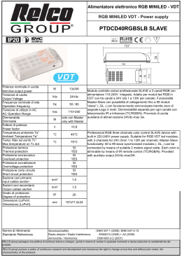
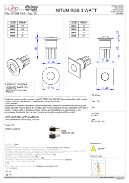
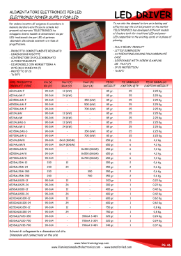
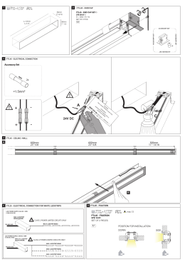
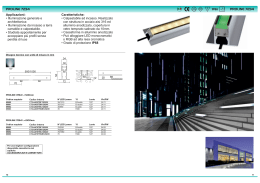
Alimentatori per LED
LED power supply
30
DLDC/RGB - DLDCC/RGB
DLDC/IRE/RGB - DLDCC/IRE/RGB
DLDC/RGB/SLX - DLDCC/RGB/SLX
67
103
DLDCC/RGB
DLDCC/RGB/IRE
DLDCC/RGB/SLX
24
mA
625
350
W
15 W/canale
7 W/canale
°C
70
70
45 W*
5 OSP/LFXX/L3S/RGB
mm2
1,5
1,5
Tasto di ON/OFF, possibilità di funzionamento
mm
1,5
1,5
master (DLDC/RGB o DLDCC/RGB) e slave
g
140
140
mm
67x103x30
67x103x30
4
4
V
RGB. Dimmerabilità separata per ogni canale con
apposito potenziometro (o tasto) ed eventuale
telecomando IR (TLC/RGB).
3 programmi a colori variabili, selezionabili con
apposito tasto.
Memorizzazione del colore/programma allo
spegnimento, anche per assenza di rete.
Modello DLDC per moduli Multichip RGB LED.
Modello DLDCC per moduli con power LED.
2
sincronizzato (DLDC/RGB/SLX o
ISTRUZIONI D’UTILIZZO
Tasto bianco (ON-OFF/Program):
- Pressione breve (<1 sec): seleziona uno dei tre programmi preimpostati, ossia arcobaleno, colori caldi, colori freddi. Permette inoltre di riattivare la modalità ciclica dopo una eventuale regolazione manuale.
- Pressione lunga (>1 sec): accende o spegne il sistema, conservando
memoria dell'ultimo colore/programma impostato
Potenziometri (R-G-B):
La rotazione di uno dei tre potenziometri associati ai tre colori interrompe
(se in funzione) la sequenza automatica e permette di regolare manualmente l'intensità luminosa dei tre canali RGB
Telecomando (opzionale):
Il tasto nero sul telecomando ha la stessa funzione di quello bianco presente sul modulo, mentre per gli altri tre associati ai colori il comportamento è il seguente
- Pressione breve (<1 sec): accende/spegne il colore corrispondente
- Pressione lunga (>1 sec): regola l'intensità del colore corrispondente,
con stop alla minima ed alla massima intensità
Assenza di alimentazione:
In caso di interruzione dell'alimentazione, al ritorno di questa viene ripristinata la situazione presente al momento dell'interruzione.
Tipi di alimentatori
I regolatori RGB DLDC-DLDCC vanno alimentati a 24V DC. Negli schemi
successivi si consiglia l'utilizzo dell'alimentatore da 40W (PTDC/40/24V).
Alimentatori di potenza inferiore possono essere usati se il numero di
moduli o strip collegati è inferiore. Possono essere usati anche alimentatori di potenza superiore (PTDC/60/24V - PTDC/90/24V) grazie alla possibilità di prelevare l’alimentazione dal modulo precedente.
HOW TO USE
White push-button (ON-OFF/Program):
- Short push (<1 sec): selects one of the three preset programs, i.e. rainbow
colours, warm colours, cold colours. It also reactivates the cycling mode
after a manual regulation.
- Long push (>1 sec): switches ON/OFF the regulator, saving the light level
for the three RGB channels
Potentiometers (R-G-B):
Acting on the three potentiometers stops the colours cycling (if one of the
cycles is in progress) and permits to dim the light level for the three channels.
IR remote control (optional):
The black push-button has the same functions of the white-one mounted on
the dimmer, the other three coloured buttons act as below described
- Short push (<1 sec): switches ON/OFF the corresponding RGB channel
- Long push (>1 sec): dims the light level of the corresponding RGB channel, stopping at maximum and minimum of the light intensity
Power supply interruption:
DLDC-DLDCC maintain the last light level for all the three channels also in
case of power supply interruption.
Types of power supply:
RGB colour controls DLDC-DLDCC must be supplied at 24V DC.In following pictures it is recomended to use 40W power supply (PTDC/40/24V).
Power supply of lower power can be used if the modules or strip to be connected are less. It can be used also power supply of higher power
(PTDC/60/24V-PTDC/90/24V) taking advantage of the possibility to connect
Master and Slave together also for 24V supply.
64
DLDCC/RGB/SLX).
1 Master + massimo 99 Slave.
Professional colour control RGB three channels
device. Each colour is dimmable by potentiometer
(or micro switch) and IR remote control on request
(TLC/RGB).
Special colours 3 programs, selectable by
dedicated push-button; power-off memory (also in
case of mains voltage interruption).
DLDC version for Multichip RGB LED modules.
DLDCC version for power LED modules.
ON/OFF push-button, master (DLDC/RGB o
DLDCC/RGB) and synchronized slave
(DLDC/RGB/SLX or DLDCC/RGB/SLX) working
options.
1 Master + max 99 Slaves.
*
Potenza totale dei moduli LED usati (15W/canale).
Total power of used LED modules (15 W each channel).
06-I/UK-1.0 Soggetto a modifiche senza preavviso, salvo errori od omissioni. Subject to change without notice. Errors and omissions excepted.
Tensione nominale entrata
Nominal input voltage
Corrente in uscita (per canale)
Output current (each channel)
Potenza di uscita (max)
Output power (max)
Temperatura max sul punto Tc
Max temperature on Tc dot
Moduli/schede LED pilotabili (max)
Maximum number of LED modules
Sezione cavi ingresso
Input cables section
Sezione cavi uscita
Output cables section
Peso
Weight
Dimensioni
Dimensions
Imballo
Packaging
Modulo controllo colore professionale a 3 canali
DLDC/RGB
DLDC/RGB/IRE
DLDC/RGB/SLX
24
Alimentatori per LED
LED power supply
115
Ch
1
1
Ch
2
2
Ch
4
3
Ch
8
Ch 16
Ch 32
34
Ch 64
Ch 128
D I P - S W I TCH
19
DMXPWM/RGB
Ch 256
06-I/UK-1.0 Soggetto a modifiche senza preavviso, salvo errori od omissioni. Subject to change without notice. Errors and omissions excepted.
-
Tensione nominale entrata (DC)
Nominal (DC) input voltage
Corrente di ingresso
Input current
Intervallo indirizzamento DMX
Addressing DMX range
N. canali DMX utilizzati
DMX channels used
Temperatura max sul punto Tc
Max temperature on Tc dot
Sezione cavi ingresso (24 V DC e DMX)
Input cables section (24 V DC and DMX)
Peso
Weight
Dimensioni
Dimensions
Imballo
Packaging
V
DMXPWM/RGB
24
mA
40
4
5
6
24 V DC
+
_
DMX +
DMX _
GND
7
8
9
PWM out
10
Interfaccia di connessione fra sistemi DMX e moduli
per il controllo colore DLDC/RGB/SLX e
DLDCC/RGB/SLX.
1÷511
Segnale di ingresso: protocollo standard DMX
512/2000.
Selezione degli indirizzi (1-511) tramite DIP-SWITCH
3
°C
60
mm2
1,5
g
50
mm
34x115x19
(codice binario).
Quando si seleziona un indirizzo il sistema assegna
in automatico il “Segnale del Colore Rosso”
50
all’indirizzo (X) scelto, il “Segnale del Colore Verde”
a quello successivo (X+1) e il “Segnale del Colore
Blu” al seguente (X+2).
Protezione all’inversione di polarità su ingressi 24 V
DC e DMX.
Peso e volumi ridotti.
Equipaggiato con morsetti ad innesto rapido.
Interface for conncetion between DMX systems and
RGB dimmers DLDC/RGB/SLX and
DLDCC/RGB/SLX.
Input signal: Standard protocol DMX 512/2000.
Binary code selection of addresses (1-511) by DIPSWITCH.
When an address is chosen, the system will
automatically assign the “Red Signal” to the
selected (X) address, the “Green Signal” to the
following one (X+1) and the “Blue Signal” to next
(X+2).
Protection against polarity inversion for 24 V DC and
DMX input.
Reduce size and weight.
Equipped with screwless terminals for fast
connection.
65
Alimentatori per LED
LED power supply
CONNESSIONI DLDCC
DLDCC CONNECTIONS
1 Master + Max 99 Slaves
PTDC/40/24V
DLDCC/RGB
MASTER
230V
V DC
+
+
-
MAX 5
MAX 20W
DLDCC/RGB/SLX
SLAVE
SLAVE IN
SLAVE OUT
MAX 5
MAX 20W
+ 98 Slaves
+
+
-
+
Fascia Rossa - RED Band
- Nessuna Fascia - No Band
OUTPUTS
Marrone - Brown
B
G
R
R
G
B
Blu - Blue
Verde - Green
Rosso - Red
+
+
+
M(+ ) B(-)
M(+)
G(-)
M(+ ) R(-)
OSP/LFXXS/RGB
M(+ ) B(-)
M(+)
G(-)
M(+ ) R(-)
OSP/LFXXS/RGB
M(+ ) B(-)
M(+)
G(-)
M(+ ) R(-)
OSP/LFXXS/RGB
Distanza [m] in funzione della sezione e del tipo di cavo di interconnessione.
Distances [m] as a function of the interconnecting cable type and section.
Type of cable
4 poles (common cathode connection)
6 poles (independent connection)
0.22 mm2
17
35
0.5 mm2
40
80
0.75 mm2
60
120
1 mm2
80
160
1.5 mm2
120
240
Cable section
NOTA:
Questo schema si riferisce all’utilizzo con SPOT in versione a 6 fili.
NOTE:
This scheme is refered to the use of 6 wires SPOTS.
66
06-I/UK-1.0 Soggetto a modifiche senza preavviso, salvo errori od omissioni. Subject to change without notice. Errors and omissions excepted.
Vin= 24V DC
Alimentatori per LED
LED power supply
CONNESSIONI DLDC
DLDC CONNECTIONS
DLDC/RGB
1 Master + Max 99 Slaves
PTDC/40/24V
MASTER
230V
Max 11 modules
Max 40W
DLDC/RGB/SLX
PTDC/40/24V
SLAVE
230V
Max 11 modules
Max 40W
DLDC/RGB/SLX
PTDC/40/24V
SLAVE
230V
Max 11 modules
Max 40W
+ 98 Slaves
+
+
Vin= 24V DC
SLAVE IN
+
Fascia Rossa
RED Band
-
Nessuna Fascia
No Band
Marrone - Brown
Verde - Green
Blu - Blue
Rosso - Red
O U T P U TS
SLAVE OUT
B
G
R
R
G
B
+
+
+
06-I/UK-1.0 Soggetto a modifiche senza preavviso, salvo errori od omissioni. Subject to change without notice. Errors and omissions excepted.
Nota: Il cavo marrone può
essere collegato
indifferentemente a
B+, G+ o R+.
Note: Brown cable can be
connected indifferentely
to B+, G+ or R+.
OSM8/300/S15/RGB + CON/OSM8/RGB/100/F
Distanza [m] in funzione della sezione del cavo di interconnessione e del numero di strip connesse.
Distances [m] as a function of the interconnecting cable section and the number of connected strips.
N. of strips
1
2
3
4
5
6
7
8
9
10
11
12
0.22 mm2
41
20
13
10
8
7
-
-
-
-
-
-
0.5 mm2
93
46
31
23
18
15
13
11
10
9
8
7
0.75 mm2
140
70
46
35
28
23
20
17
15
14
13
11
1 mm2
185
93
62
47
37
31
27
23
20
18
17
15
1.5 mm2
280
140
93
70
55
46
40
34
30
27
25
22
Cable section
67
Scaricare