Electronic
Pressure Measurement
Electronic pressure switch with display
Model PSD-10
WIKA Data Sheet PE 81.13
Applications
n
n
n
n
Hydraulic and pneumatic applications
Filter
Pumps
Machine tools
Special features
n
n
n
n
n
4-digit display
Switch points freely programmable
Switching output 2 may be used as error output
Rotatable case 280°
Optional analogue output
Description
Comfortable handling
Robust and compact design combined with easy handling
are the features of these state-of-the-art pressure switches.
The well-conceived form with slanted display and a large
indication, which rotates by 280°, enables the user to read
off measurements from various directions, even under
difficult lighting conditions or from a distance. Unit, set
points as well as zero point and span can easily be
configurated by means of the self-explanatory menu. The
adjustable password provides protection from unauthorised
access.
Proven measuring technologies
Sensors made by WIKA have guaranteed high accuracy,
long-term stability and repeatability in industrial pressure
measurement for decades. The appropriate sensor
principle used - either metal thinfilm or ceramics - depends
on the respective measuring range. As it is designed for
rugged environments, the pressure switch is extremely
resistent to interference, shocks and vibrations.
WIKA Data Sheet PE 81.13 · 10/2005
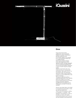
Fig. Pressure switch PSD-10
The PSD-10 provides the user with an instrument with
excellent switching functionality. It is ideally suited for
permanent use in series production in industrial
applications.
Elaborate functions
As it is equipped with up to two switching outputs, which
can be individually configurated, a pressure display as well
as an optional analog output, the PSD-10 combines the
tasks of a pressure switch, a digital display and a pressure
transmitter. A switching output as well as an LED can also
be used as error status indicator according to the DESINA®
concept.
Versatile and multifaceted
The efficient copying of requested settings and functions to
other pressure switches is enabled by means of an optional
programming module. A fast and easy mounting can be
realised with the optional mounting bracket.
Page 1 of 6
Specifications
Model PSD-10
Ceramic sensor
Pressure ranges
Over pressure safety
Burst pressure
bar
bar
bar
- 1 ... 2.5 -1 ... 4
10
10
12
12
-1 ... 6
20
25
-1 ... 10
20
25
-1 ... 16
40
50
Thin-film sensor
Pressure ranges
Over pressure safety
Burst pressure
bar
bar
bar
25
50
250
60
120
550
100
200
800
160
320
1000
Materials
n Wetted parts
Display
n Design
n Range
n Accuracy
Current consumption
Accuracy
600
1200
2400
Zinc diecust Z 410; lacquered silver-coloured
Polyester
UB in DC V
15 < UB ≤ 30 (nominal 24 DC V protection class 3)
{0/4 ... 20 mA; programmable and freely adjustable}
RA in Ohm
RA ≤ (UB – 8 V) / 0.02 A (max. 500 Ohm)
Individually adjustable via external control keys
1 or 2 (PNP)
NO / NC; windows- and hysteresis function freely adjustable
Supply voltage UB – 1.5 V (UB in Volt)
1.4 A (for two wired outputs 0.7 A per switch)
DC V
2)
n Response time
n Accuracy
400
800
1700
Others sealing materials on request
n Case
n Keyboard
Switch points
n Number
n Function
n Contact rating
2)
n Switching current
250
500
1200
Stainless steel, with ceramic sensor additional
1)
Ceramic AL2O3, NBR
1)
Power supply UB
Signal output and
maximum load RA
40
80
400
Higher contact rating on request
ms
% of span
≤ 10
≤ 1.0
7-Segment-LED, red 4-digit, height 9 mm
- 999 ... 9999
% of span
mA
≤ 1.0 ± 1 digit
≤ 100
% of span
% of span
≤ 0.5 (BFSL)
3)
≤ 1.0
3)
Including non-linearity, hysteresis, non-repeatability, zero point and full scale error (corresponds to error of
measurement per IEC 61298-2). Adjusted in vertical mounting position with lower pressure connection.
Non-linearity
1-year stability
% of span
% of span
Permissible temperature of
4)
n Medium
4)
n Ambient
4)
n Storage
4)
Compensated temperature range
Temperature coefficients within
compensated temp range
n Mean TC of zero
n Mean TC of range
{}
(BFSL) according to IEC 61298-2
≤ 0.2
(≤ 0,3 with pressure range ≤ 16 bar) (at reference conditions)
-30 ... +100 °C
-22 ... +212 °F
(-20 ... +85 °C with pressure range ≤ 16 bar)
(-4 ... +185 °F with pressure range ≤ 16 bar)
-20 ... +85 °C
-40 ... +100 °C
-4 ... +185 °F
-40 ... +212 °F
Also complies with EN 50178, Tab. 7, Operation (C) 4K4H, Storage (D) 1K4, Transport (E) 2K3
0 ... +80 °C
% of span
% of span
a-conformitiy
Wiring protection
Load alternation
Mass
< 0.4
32 ... +176 °F
≤ 0.3 / 10 K
≤ 0.3 / 10 K
89/336/EWG interference emission and immunity see EN 61 326
Interference emission limit class A and B
97/23/EG Pressure equipment directive
Protected against reverse polarity and short circuiting on the instrument side
kg
Typ. 100 millions (10 millions with pressure range ≤ 16 bar)
Approx. 0.28
Items in curved brackets are optional extras for additional price.
Page 2 of 6
WIKA Data Sheet PE 81.13 · 10/2005
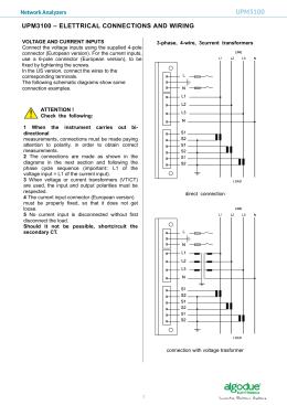
Dimensions in mm
Ingress Protection IP per IEC 60 529
Electrical connections
L-connector
DIN EN 175301-803, Form A
for conductor cross section up to
max. 1.5 mm² ,
conductor outer diameter 6 - 8 mm,
IP 65
Order code: A4
Circular connector *)
M 12x1, 5-pin
IP 67
Order code: M5
Circular connector *)
M 12x1, 4-pin
IP 67
Order code: M4
OK
Pressure connections
G 1/2,
Order code: GD
G 1/4,
DIN 3852
Order code: HD
(max. over pressure safety 600 bar)
G 1/4 female
Order code: TB
Others on request
For installation and safety instructions see the operating instructions for this product.
For tapped holes and welding sockets please see Technical Information IN 00.14 for download at
www.wika.de -Service
*) Connectors are not included in delivery
WIKA Data Sheet PE 81.13 · 10/2005
Page 3 of 6
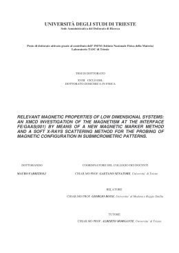
Wiring details
Circuit diagram
Output
{1 Switching output}
L-connector
2 Switching outputs
Circular connector
M12x1
4-pin
{1 Switching output +
1 analogue output}
Circular connector
M12x1
4-pin
{2 Switching outputs +
1 analogue output}
Circular connector
M 12x1
5-pin
Desina
Legend:
{}
out 1
external Load 1
out 2
external Load 2
Sig+
Analogue output
Items in curved brackets are optional extras for additional price.
WIKA Data Sheet PE 81.13 · 10/2005
Page 4 of 6
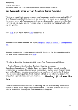
Hysteresis function
If the system pressure fluctuates around the nominal value, the
hysteresis keeps the switch status of the outputs stable. When
the system pressure is rising, the output switches when it
reaches the respective set point (SP); if the pressure falls again,
the output switches back only if the reset point (rSP) is reached.
Application example: loading an accumulator.
The shut-off valve loads up to 8o bar and then shuts off. When
70 bar is reached again, it switches on once more,
Window function
The window function allows the monitoring of a defined range.
If the system pressure is between the set point (SP) and the
reset point (rSP), the output is activated (NO) respective
deactivated (NC).
Delay times (0,00 to 9,99 s):
By this means unwanted pressure peaks of short duration or
high frequency can be filtered out.
The pressure must remain for at least this time to enable the
switch to operate. The switching output does not immediately
change its status when it reaches the switching event, but only
after the delay time has elapsed. If the switching event no longer
pertains when the delay time has elapsed, the switching output
does not change.
Error function
Switching output 2 can be used optionally as an error output to
display pressure switch function errors. As an error output it is
normally closed and in case of errors (Er1, Er2, Er3) it is open. At
the same time LED II lights up. The display and the output
remain active until the error is cleared.
Further informations
You can obtain further information (data sheets, instructions, etc.) via Internet address www.wika.de
Specifications and dimensions given in this leaflet represent the state of engineering at the time of printing.
Modifications may take place and materials specified may be replaced by others without prior notice.
WIKA Data Sheet PE 81.13 · 10/2005
Page 5 of 6
Parameter
Factory setting
Adjustable range
Please fill in!
Switching output 1
Upper set point
Full scale value
Pressure range (enter as pressure value)
__ __ __ __
Lower set point
Full scale value - 10 %
Pressure range (enter as pressure value) 1)
__ __ __ __
Switching function
NO
NO
NC
Switching type
Hysteresis
Window
Hysteresis
o
o
o
o
Time delay for the upper set point
Time delay for the lower set point
0.05 s
0.05 s
0.00 ... 9.99 s
0.00 ... 9.99 s
__ , __ __
__ , __ __
Switching output 2
Upper set point
Lower set point
Full scale value
Full scale value - 10%
Pressure range (enter as pressure value)
Pressure range (enter as pressure value) 1)
__ __ __ __
__ __ __ __
Switching function
NO
NO
NC
Switching type
Hysteresis
Window
Hysteresis
o
o
o
o
Time delay for the upper set point
Time delay for the lower set point
0.05 s
0.05 s
0.00 ... 9.99 s
0.00 ... 9.99 s
__ , __ __
__ , __ __
Options
Password
0000 (= no password)
0000 ... 9999
__ __ __ __
Displayed unit
bar
MPa
PSI
Displayed parameter
Actual pressure
o
o
o
o
o
o
o
o
o
o
o
*)
bar
Max-value
Min- value
Display off
Switching output 2
Switching output 1
Actual pressure
Analogue output
4-20 mA
4-20 mA
0-20 mA
Initial pressure value
(analogue output)
Initial pressure value = 4mA Pressure range (enter as pressure value)
4mA
Full scale pressure value
(analogue output)
Full scale value = 20 mA
Pressure range (enter as pressure value) 2)
Zero offset
Factory setting
Factory setting
Adjustment to actual pressure 3)
Reset of peak value memory
Do not delete memory
Delete memory
Do not delete memory
Switching output 2 used as
error output
No
Yes
No
Software version
---
---
Number of displayed decimals
4)
Lowering by 1 decimal
__ __ __ __
__ __ __ __
Back to menu
o
The lower set point must be 0.5% of full scale value below the upper set point minimum.
The full scale pressure value (analogue output) must be 5% of span above the initial pressure value (analogue output).
Max. 5% of full scale.
Depends on pressure range and engineering unit (3 digits for bar, 4 digits for psi).
In case of blank fields the pressure switch will be adjusted to the factory setting.
Page 6 of 6
WIKA Data Sheet PE 81.13 · 10/2005
WIKA Alexander Wiegand GmbH & Co. KG
Alexander-Wiegand-Straße 30
63911 Klingenberg / Germany
Phone (+49) 93 72/132-0
Telefax (+49) 93 72/132-406
E-Mail [email protected]
www.wika.de
9039171 10/2005 GB
1)
2)
3)
4)
*)
o
o
Scaricare