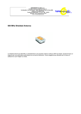
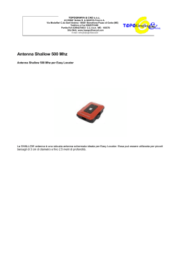
TUNING INSTRUCTIONS
INSTALLATION
1) Hole mount installation
A) Hole Drilling: Chose the position on your vehicle (centre roof is
recommended) and drill a hole according to the mount diameter.
Please ensure a good electrical ground contact is made.
B) Connections: Position the cable in your vehicle shortening its
length according to your needs. Connect the PL259-male to the
cable ready for the connection to the transceiver.
C) Electrical Tests: Ensure there is no short circuit between the
central pin and the nut of the connector. Ensure there is electrical
continuity of the cable from the central pin (connector side) to
the central contact (antenna side). Ensure there is electrical
continuity of the cable from the nut (connector side) to the
ground (antenna side)
REMARKS: As some antennas are in short circuit and it would be
impossible to do the test after the installation, we recommend
you test the cable prior to connecting the antenna.
D) Installation: Pay attention to securing all screws and nuts
during the final installation.
E) Suggestion: After the final installation and BEFORE connecting
your transceiver, we recommend an electrical continuity check
between the nut of the PL259 and the ground of your vehicle.
2) Special mounts installation: Follow the same instructions
of Point 1.
3) Magnetic mount installation: Follow the instructions
supplied with the magnetic mount.
TUNING
Most of the antennas are factory tuned and don’t need any extra
tuning, but in case of fine adjustments we recommend to follow
the procedure below:
A) To perform a correct test, move to an open space far from
metal parts such as metal doors, buildings, towers, gates etc. at
minimum 50 metres or more.
B) Connect your SWR-meter between the antenna connector
and your CB transceiver (follow the instructions of your SWRmeter for the correct use to your equipment).
C) The following procedure is used for the tuning of the 40
channels CB-band Radio in the range of:
CH-1 = 26.965 MHz to CH-40 = 27.405 MHz with CH-19 =
27.185 MHz as centre band for EU Frequencies.
CH-1 = 27.601 MHz to CH-40 = 27.991 MHz with CH-19 =
27.781 MHz as centre band for UK Frequencies.
Select CH-1 on your CB-transceiver and take an SWR
measurement, writing down the results. Transmit only for a
few seconds because in case the SWR is too high the
transceiver could be damaged.
D) Repeat the procedure for CH-19 and CH-40
E) If all SWR results are very high (more than 3) probably there’s a
short circuit in the cable or your antenna is defective. To avoid
damages to your CB transceiver DO NOT use it until the
problem is rectified.
F) If the SWR results are the same on CH-1 and CH-40 and the
lower value is on CH-19, your antenna doesn’t need any tuning.
G) If the SWR result on CH-1 is lower than CH-40 your antenna is
electrically TOO LONG and you should slightly cut the radiator by
10mm at a time. Avoid cutting too much. As long as you get the
same values on CH-1 as well as CH-40.
H) If the SWR result on CH-40 is lower than CH-1 your antenna is
electrically TOO SHORT and you need to pull out the radiator as
long as you get the same values on CH-1 as well as CH-40.
B Copyright SIRIO antenne - Technical Data are subjected to change - Printed in ITALY - Rev. 12/07/2010 - Cod. ID407
NEW TITANIUM 3001 series
NEW TITANIUM 3001 MAG
TARATURA
Le antenne sono pre-tarate in fabbrica pertanto nella maggior
parte dei casi non necessitano di taratura. In caso si renda
necessaria una leggera taratura consigliamo di seguire la
procedura riportata di seguito.
A) Recarsi in spazio aperto ad almeno 50 metri o più da oggetti
metallici quali cancelli, lampioni, edifici o tralicci.
B) Collegare un SWR-meter (ROS-metro) tra il connettore
dell’antenna e il trasmettitore CB. Seguire le istruzioni del ROSmetro per il corretto utilizzo dell’apparato.
C) La seguente procedura si applica per la taratura dei 40 canali
omologati per banda CB compresi nel range di frequenza da CH1 = 26.965 MHz a CH-40 = 27.405 MHz con CH-19
=27.185MHz in centro banda.
Selezionare il CH-1 sul trasmettitore CB ed effettuare la misura di
SWR annotandone il valore. Trasmettere sempre per pochi
secondi perché se l’ SWR fosse molto alto si potrebbe
danneggiare il trasmettitore.
D) Ripetere l’operazione anche per il CH-19 e il CH-40.
E) Se tutti e tre i valori di SWR sono molto alti (maggiori del valore
3) o tendenti a infinito, probabilmente è presente un corto
circuito nel cablaggio oppure l’antenna è guasta. Per evitare di
danneggiare il vostro trasmettitore CB NON utilizzarlo
finché il problema non sarà risolto.
F) Se i valori di SWR sono uguali per CH-1 e CH-40 e il valore
minimo si ha su CH-19, la vostra antenna non necessita di alcuna
taratura.
G) Se il valore di SWR è più basso su CH-1 rispetto a CH-40, la
vostra antenna é elettricamente “lunga”, quindi accorciare lo stilo
di circa 10mm alla volta fino ad ottenere gli stessi valori di SWR sia
su CH-1 che su CH-40.
H) Se il valore di SWR è più basso su CH-40 rispetto a CH-1, la
vostra antenna é elettricamente “corta”, quindi allungare lo stilo
sfilandolo di 10mm alla volta fino ad ottenere gli stessi valori di
SWR sia su CH-1 che su CH-40.
NEW TITANIUM 3001
ISTRUZIONI DI TARATURA
INSTALLAZIONE
1) Installazione con foratura della carrozzeria:
A) Foratura: Praticare il foro del diametro richiesto nella posizione
desiderata (consigliato a centro tetto). Togliere la vernice nella
parte interna della carrozzeria per garantire un buon contatto
elettrico di massa.
B) Collegamenti: Posizionare il cavo dell’antenna accorciandolo
in base alle necessità, quindi montare il connettore PL 259
maschio per la connessione all’apparato CB.
C) Verifiche elettriche: Assenza di corto circuito tra spina centrale
e ghiera di massa del connettore, continuità elettrica del
conduttore centrale da un’estremità all’altra del cavo, continuità
elettrica calza cavo dalla ghiera lato connettore al contatto di
massa lato connettore d’antenna.
N.B.: Si consiglia di testare il cavo lasciandolo scollegato
dall’antenna poiché alcune antenne sono elettricamente in corto
circuito e non è possibile eseguire il test ad installazione
completata.
D) Installazione: Completare il montaggio dell’antenna serrando
adeguatamente viti e bulloni.
E) Consiglio: a montaggio terminato e PRIMA di connettere il
trasmettitore, si consiglia di verificare la continuità elettrica tra la
ghiera del connettore PL 259 e un punto di massa della
carrozzeria.
2) Installazione con attacchi speciali: seguire la stessa
procedura del punto 1.
3) Installazione temporanea con basi magnetiche: seguire
le istruzioni fornite con la base magnetica ricordandosi che si
tratta di un’installazione TEMPORANEA.
DESCRIPTION
CB vehicular antennas made of very high quality materials and very flexible conical stainless steel
rod. It is easily tiltable by acting on the spheric joint by means of the safety set screw and key-ring
supplied. For the fine tuning please pull up the rubber cap, release the steel rod as indicated in the
picture and slightly cut the steel rod from the bottom to get the best tuning. TITANIUM 3001 is
supplied with UHF-PL259 connection for the standard installation on magnetic mounts or SO239
sockets, TITANIUM 3001 MAG is supplied with MAG 125 PL
N-PL-AS optional mount Mountiing Hole: Æ 12.5mm
SPECIFICATIONS
Nota: la cartina autoadesiva è INDISPENSABILE per il corretto funzionamento elettrico della base magnetica.
Remark: for a correct electric performance of magnetic mounts it’s NECESSARY to apply the pvc sticker.
Technical Data:
Type
: Base loaded
Impedance
: 50 W
Frequency Range
: 27 ... 28.5 MHz
Polarization
: Vertical
SWR @ freq. res.
: £ 1.4
Bandwidth @ SWR £2 : ³ 1300 KHz (115 channel)
Max. Power
: 300 Watts (CW) continuous,
900 Watts (CW) short time
Height (approx.)
: 1485 mm
Weight (approx.)
: 300 gr
Mounting
PL version
: UHF-male (PL 259), cable not supplied
N version
: N-PL-AS, hole Æ 12.5mm, 4m RG 58
MAG version
: MAG 125 PL magnetic mount,
3.6m RG 58, PL259
a) Dopo aver pulito la superficie del magnete con
straccio e alcool, staccare la cartina autoadesiva in
pvc argento dal supporto (foto 1) ed applicarla in
modo uniforme e senza pieghe (foto 2 e 3).
(1)
a) Clean the surface of the magnet by using a cloth and
alcohol and apply the pvc sticker paying attention to
keep the surface as smooth as possible (pict. 1, 2, 3).
Tuning system
Istruzioni generali per basi magnetiche / General instruction for magnetic mounts
1. L’installazione di antenne veicolari mediante base magnetica è da ritenersi una soluzione TEMPORANEA
poichè la base magnetica non può garantire la stessa tenuta di una base fissa. Si consiglia per tanto, per la vostra e
l’altrui sicurezza, di NON SUPERARE I 110 Km/h.
2. La posizione più idonea per il corretto funzionamento della base magnetica è a centro tetto del veicolo. In taluni
casi è possibile installarla in posizioni alternative (bordo tetto o baule) a patto che le superfici di appoggio nella
zona di contatto della base magnetica siano sufficientemente piane da garantire la corretta tenuta della base.
Durante la prima installazione si consiglia di prestare attenzione alla tenuta della base magnetica durante la marcia
per verificarne l’adeguatezza di montaggio.
3. Consigliamo vivamente di rimuovere la base magnetica quando inutilizzata in modo da evitare l’accumulo di
sporcizia al di sotto della stessa e i conseguenti danni alla carrozzeria del veicolo. Una sosta prolungata sotto il
sole, soprattutto durante i mesi estivi, può far innalzare la temperatura del tetto del veicolo fino a 70/80 gradi
centigradi con conseguenti seri danni sia alla base magnetica che alla carrozzeria. Si consiglia per tanto di
rimuoverla sempre dopo ogni utilizzo. Si raccomanda la rimozione anche prima di entrare nell’autolavaggio.
1. Magnetic mounts are only suitable for temporary installation and are not safe or strong as fixed body mounts so
for your own safety as well as the safety of other road users please DO NOT EXCEED THE SPEED LIMITS OF
110 Km/h OR 70 MPH.
2. For optimum results the magnetic base should be fixed on the centre of the car roof, however alternative
mounting positions can be used as long as the surface is flat enough to guarantee a strong installation. Pay
particular attention to the stability of your magnetic mount to ensure safety during driving.
3. It is recommended that your magnetic mount is removed after each time it is used, so that any dirt can be removed
before the magnet is used again. Also do not leave the vehicle parked in direct sunlight for long periods with the
magnet installed as high temperatures (70 / 80 °C) can damage the magnetic base and car body. We strongly
recommend that you always remove your magnetic mount after each use and before visiting a car wash
ID407
MAG 125 PL
magnetic standard mount for MAG version
(2)
(3)
b) Ritagliare la cartina con un taglierino appoggiando
la base su una superficie di cartone o gomma (foto 4)
b) Cut the pvc sticker following the magnetic shape.
Be careful to use a carton layer when cutting to avoid
damages to the working surface (pict. 4)
(4)
c) Montare la membrana di protezione in gomma (foto 5)
c) Assemble the rubber protection (pict. 5)
(5)
HI-QUALITY ANTENNAS MADE IN ITALY
S
SIRIO
antenne
Scaricare