LIBRETTO ISTRUZIONI
NOTICE DE MONTAGE
INSTRUCTIONS MANUAL
AQUADECOR
Leggere attentamente il presente foglietto
illustrativo.
Il costruttore non si ritiene responsabile per
installazioni non conformi a quanto riportato e
per l'utilizzo di materiali o accessori non forniti
dalla stessa.
Il radiatore va installato ad un'altezza minima
da terra di 150mm, posizionato perfettamente a
bolla come indicato in figura utilizzando il kit di
fissaggio fornito a corredo.
Gli attacchi del radiatore che non vengono
utilizzati, devono essere chiusi con i tappi
forniti a corredo.
La pressione massima di utilizzo è di 4 bar,
l'impiego è solo come uso riscaldamento con
temperatura dell'acqua tra i 30 e i 90 °C.
Avant toute opération de montage, lire
attentivement la présente notice.
Toutes les opérations d’installation et
d’entretien doivent
être faites par
du
personnel qualifié.
Le fabricant décline toute responsabilité en cas
de montage non conforme aux indications de la
présente notice et en cas d’emploi de matériel
ou d’accessoires livrés par des tiers.
Le radiateur doit être installé à une hauteur
minimum du sol de 150 mm. et fixé en utilisant
le kit de fixation fourni de série.
Les connexions pas utilisées doivent être ferme
avec le bouchon fourni avec le kit.
La pression maxi de service est de 4 bar ; il faut
utiliser le radiateur seulement en chauffage
avec la température de l’eau entre 30 °C 90 °C.
Read carefully the present illustrative folder.
Manufacturer is not responsible for the installations not in conformity with what is reported
hereby and for the use of materials or accessories not supplied by it self.
The radiator must be installed at the minimum
high of 150 mm from the ground, perfectly lined
and balanced as indicated on the picture here
above, using the supplied fixing kit.
The connections of the radiators which are not
used, must be closed with the supplied caps.
The maximum using pressure is of 4 bars. Its
use is only for heating, with water temperature
between 30° and 90°.
Pressione Max di esercizio 4 bar - Temperatura Max esercizio 90° C
Pressure 4 bars - Max Working Temperature 90° C
Pression Maxi de service 4 bar - Temperature Maxi de service 90° C
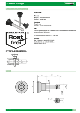
AQUADECOR - INSTALLAZIONE VERTICALE - INSTALLATION VERTICALE - VERTICAL INSTALLATION
BURANO PLUS V/O- Installazione VERTICALE - Vertical Installation
L - 180
15
15
TasselloBloccaggio
Bloccaggio
Tassello
Blockingpiece
piece
Blocking
Vis de Blocage
120
Sfiato
120
15
n°n°2 2
Pezzi
Pezzi
n°
n˚22Pieces
Pieces
n° 2 Pieces
90
90
20
90
20
Kit di Fissaggio
Kit di
Fissaggio
Fixing
Kit
Fixing Kit
Kit -de Fixation
Ø8
n°n°2 2
Pezzi
Pezzi
n°
n˚22Pieces
Pieces
n° 2 Pieces
Ø8
H
H - 210
n°
n°22Pezzi
Pezzi
n° 2 Pieces
n˚ 2 Pieces
n° 2 Pieces
I = (H- 40)
Staffa- -Bracket
Bracket- - Console
Staffa
Appoggio
- Support
- Support
Appoggio
- Support
90
n°
8 8
n°22Pezzi
Pezziø Ø
n° 2
n˚
2 Pieces
PiecesøØ8 8
n°
12
n° 22Pezzi
Pezziø Ø12
n° 2
2 Pieces
Pieces øØ12
12
n˚
n° 2 Pieces ø 12
75
20
n° 2 Pieces ø 8
75
L - 150
75
37,5
I= L-75
37,5
20
Ø 12
90
45
Ø 12
n°
n°22Pezzi
Pezzi
n° 2 Pieces
n˚
2 Pieces
n° 2 Pieces
37,5
L
SequenzadidiMontaggio
Montaggio -- Sequence
Sequence ofofAssembly
Sequenza
Assembly
110
Sequence de Montage
30
Staffa - Bracket
Consolg
Staffa
- Bracket
1
2
Ø8
Appoggio
Appoggio
Support
Support
Support
Min 150
Min 150
4
Tassello Bloccaggio
Ø 12
70
Tassello Bloccaggio
Tassello
Bloccaggio
Blocking piece
piece
VisBlocking
de Blocage
Tassello
Bloccaggio
Blocking piece
piece
VisBlocking
de Blocage
3
Verificareche
cheililfissaggio
fissaggio risulti
Verificare
risultistabile
stabilee esicuro
sicuro
Verify
that
the
fixing
results
stable
Verify that the fixing results stableand
andsure
sure
Verifier que les fixations stables et sures
2
Max Working Pressure 4 bars - Max Working Temperature 90˚ C
/
Pressione Max di esercizio 4 bar - Temperatura Max esercizio 90° C
-
RADIATORE VIENE
VIENE FORNITO
ILILRADIATORE
FORNITO CON
CON IL
IL DIVISORIO
DIVISORIO"D"
"D"CHIUSO
CHIUSO
The
Radiator
is
Supplied
with
Flow
Distributor
"D"
Close
The Radiator is Supplied with Flow Distributor "D" Close
LE RADIATEUR EST FOURNIE AVEC LA PASTILLE “D” FERMÉE
!
1/8"
H = 1500 - 1800 - 2000
1/2"
25
0
Ø1
4
P
1/2"
1/2"
1/2"
1/2"
"D"DIVISORIO
DIVISORIO Chiuso
"D"
Chiuso
FlowDistributor
Distributor "D"
Flow
"D"Close
Close
A
"D" Pastille fermée
P
POSIZIONE DIVISORIO "D" - Position of Flow Distributor
POSIZIONE DIVISORIO "D" - Position of Flow Distributor
Position Pastille “D”
3-5
78
N.Elem.
A mm
6-9
154
"D"
"D" DIVISORIO
DIVISORIO
FlowDistributor
Distributor "D"
Flow
"D"
10-14
230
"D" Pastille
Collegamenti Idraulici
Possibili
- Possible
Water
Connections
- Connexions
hydraulique
Collegamenti
Idraulici
Possibili
- Possible
Water
Connections
FIG 1
FIG 2
FIG 3
S
S
S
Ø14
P
"D" CHIUSO
CHIUSO
"D"
"D" Close
Close
"D"
"D" CHIUSO
CHIUSO
"D"
"D" Close
Close
"D"
"D" Fermé
"D" Fermé
FIG 4
S
Ø14
P
"D"APERTO
APERTO
"D"
"D" Open
Open
"D"
"D" Ouvert
3
"D"APERTO
CHIUSO
"D"
"D" Open
Close
"D"
"D" Fermé
AQUADECOR - INSTALLAZIONE ORIZZONTALE - INSTALLATION HORIZONTAL - HORIZONTAL INSTALLATION
BURANO PLUS V/O - Installazione ORIZZONTALE - Horizontal Installation
Kit di Fissaggio - Fixing Kit - Kit de Fixation
Kit di Fissaggio - Fixing Kit Tassello Bloccaggio
Tassello
Bloccaggio
Blocking
piece
Blocking
piece
Piece de Blocage
Staffa - Bracket
Staffa - Bracket
Console
Appoggio - Support
Support
n°
øØ
8 8
n°22Pezzi
Pezzi
n° 22 Pieces
88
n˚
PiecesøØ
n° 2 Pieces ø 8
n°
12
n°22Pezzi
Pezziø Ø12
n° 2
2 Pieces
Pieces øØ12
12
n˚
n° 22 Pezzi
Pezzi cad
n°
cad.
n° 2 Pieces cad
n˚ 2
Pieces
cad.
n° 2 Pieces
n° 2 Pieces ø 12
50
Sfiato
95
50
H - 100
Ø 12
Ø 12
Ø8
L - 190
Ø8
L - 190
Ø8
Ø 12
I = (H- 40)
20
95
20
20
H
Sequenza
di Montaggio
Montaggio- Sequence
- Sequence
of Assembly
Sequenza di
of Assembly
Sequence de Montage
110
Staffa -- Bracket
Staffa
Bracket
28
Consolg
1
2
Appoggio
Appoggio
Support
Support
Support
Ø 8
3
Ø 12
Min 150
70
Tassello Bloccaggio
Tassello
Bloccaggio
Blocking piece
piece
VisBlocking
de Blocage
4
Tassello Bloccaggio
Tassello Bloccaggio
Blocking piece
Vis Blocking
de Blocagepiece
Min 150
37,5
95
L
I= L-75
95
37,5
50
Sfiato
Verificare
il fissaggio
risulti
stabile
e sicuro
Verificareche
che
il fissaggio
risulti
stabile
e sicuro
Verify
the
fixing
results
stable
and and
sure sure
Verifythat
that
the
fixing
results
stable
Verifier que les fixations stables et sures
4
1/8"
1/2"
"D"
"D" DIVISORIO
DIVISORIO
Flow Distributor
Distributor "D"
Flow
"D"
1/2"
"D" Pastille0
"D"
Chiuso
"D"DIVISORIO
DIVISORIO Chiuso
FlowDistributor
Distributor "D"
Flow
"D"Close
Close
P
"D" Pastille fermée
A
1/2"
1/2"
1/2"
H = 1500 - 1800 - 2000
4
Ø1
POSIZIONE DIVISORIO "D" - Position of Flow Distributor
POSIZIONE DIVISORIO "D" - Position of Flow Distributor
Position Pastille “D”
3-5
78
6-9
154
10-14
230
P
0
N.Elem.
A mm
25
Max Working Pressure 4 bars - Max Working Temperature 90˚ C
!
IL RADIATORE
VIENEFORNITO
FORNITOCON
CONILILDIVISORIO
DIVISORIO"D"
"D"CHIUSO
CHIUSO
IL RADIATORE
VIENE
The
Radiator
is
Supplied
with
Flow
Distributor
"D"
Close
The Radiator is Supplied with Flow Distributor "D" Close
LE RADIATEUR EST FOURNIE AVEC LA PASTILLE “D” FERMÉE
Collegamenti
Idraulici
Possibili
- Possible
WaterWater
Connections
- Connexions
hydraulique
Collegamenti
Idraulici
Possibili
- Possible
Connections
FIG 1
FIG 2
S
Pressione Max di esercizio 4 bar - Temperatura Max esercizio 90° C
-
/
S
"D" CHIUSO
CHIUSO
"D"
"D" Close
"D"
Close
"D" CHIUSO
CHIUSO
"D"
"D" Close
"D"
Close
"D" Fermé
"D" Fermé
FIG 3
FIG 4
S
S
"D" APERTO
APERTO
"D"
"D" Open
Open
"D"
"D"APERTO
APERTO
"D"
"D" Open
Open
"D"
"D" Ouvert
"D" Ouvert
P
Ø14
Ø14
P
La pastille a ouvrir est toujours celui ou l’eau doit sortir
5
AQUADECOR - VERTICALE SINGOLO - VERTICAL SIMPLE - VERTICAL SINGLE
MURANO PLUS - Istruzioni per l'installazione - Installation Instructions
112÷122
L - 150
75
D
20
75
E
76
F
1/2"
1/2"
C
Ø 12 (B)
150 Min
Ø 12
1/2"
Ø 12 (B)
C
F
29
1/2"
H = 1500; 1800; 2000
I
H - 105
Ø 12
37,5
1/2"
I= L-75
20
1/2"
D
37,5
72÷82
L=(n.el x 75)
FISSAGGIO A MURO
FIXATION AU MUR
Tenendo presenti le quote riferite ai punti di
En suivant les mesures de la figure au point “B”
foratura B, indicate in figura praticare sul muro n°
effectuer sur le mur 3 trous de Ø 12 mm., insérer dans
3 fori Ø12 mm, inserire i tasselli "fischer" ed
les trous les chevilles “Fischer” et bloquer les trois
utilizzando le viti F bloccare le 3 staffe C; montare
consoles C avec les vis F.
i 3 patricolari D e bloccarli alla corretta distanza dal
Monter les 3 détails “D” et le bloquer avec le vis “E”
muro utilizzando le viti E. Utilizzando le asole di
au correcte distance du mur. Positionner le détail “C”
regolazione in corrispondenza delle viti di
perfectement au niveau
fissaggio, posizionare i particolari C perfettamente
Monter le radiateur sur les trois consoles “D”.
a bolla.
Monter sur le radiateur le vanne, le purgeur, et le
Montare
al
radiatore,
le
valvole,
lo
sfiato
e
gli
bouchon;
Leggere attentamente il presente foglietto illustrativo.
eventuali
tappi.(Attenzione
sondino
dello per
sfiato,
Attention
la sonde du purgeur doit être orientée vers
La TONONFORTY
S.p.A. non sialritiene
responsabile
installazioni
non
conformi
a quanto
riportato
e perl'alto)
l'utilizzo di materiali o accessorila
non
deve
essere
orientato
verso
partie haut
forniti dalla stessa.
Agganciare
il radiatore ai particolari D delle 3
Faire attention à ne pas abîmer la peinture.
Il radiatore va installato ad un'altezza minima da terra di 150mm,
mensole
di
sostegno.
Veiller à ce que le radiateur soit fixé d’une manière
posizionato perfettamente a bolla come indicato in figura utilizzando il kit di
Accertare
che ailcorredo.
radiatore sia fissato in modo
stable et sûre.
fissaggio fornito
Gli attacchi
del radiatore che non vengono utilizzati, devono essere
chiusi
stabile
e sicuro.
Compléter
les connexions hydraulique (avant d’ouvrir
con i tappi forniti
corredo.
Completare
il acollegamento
idraulico (prima di
le vanne vérifier que la pression soit inférieure a 4 Bar)
La pressione massima di utilizzo è di 4 bar, l'impiego è solo come uso
aprire
le valvole
accertaredell'acqua
che la tra
pressione
sia
et faire sortir l’air du radiateur par le purgeur.
riscaldamento
con temperatura
i 30 e i 90 °C.
inferiore ai 4 bar) e sfiatare completamente il
FISSAGGIO A MURO
radiatore.
Tenendo presenti le quote riferite ai punti di foratura B, indicate in figura
praticare sul muro n° 3 fori Ø12 mm, inserire i tasselli "fischer" ed
utilizzando le viti F bloccare le 3 staffe C; montare i 3 patricolari D e
WALL
MOUNTING
bloccarli alla corretta distanza dal muro utilizzando le viti E. Utilizzando le
Considering
the measurements
referred
todithe
hole points
‘B’, indicated
on the picture, make n. 3 holes Ø 12
asole di regolazione
in corrispondenza
delle viti
fissaggio,
posizionare
i
particolari
C wall,
perfettamente
a bolla.
mm
into the
then insert
the fisher screws and fix the 3 brackets ‘C’ with the screws ‘F’. Install the 3 parts
radiatore,
le valvole,
lo sfiato
e gli eventuali
tappi.(Attenzione
al the wall using the screws ‘E’. Place the parts
‘D’Montare
and fixalthem
paying
attention
in respecting
the
distances from
sondino dello sfiato, deve essere orientato verso l'alto)
‘C’Agganciare
in the correct
way, using the regulation slots by the fixing screws.
il radiatore ai particolari D delle 3 mensole di sostegno.
Install
the radiator,
the valves,
theinair
valve
andethe
possible caps (be careful the feeler of the air valve should be
Accertare
che il radiatore
sia fissato
modo
stabile
sicuro.
Completare
il collegamento idraulico (prima di aprire le valvole accertare
fixed
upwards).
pressioneto
siathe
inferiore
ai 4 of
bar)
e sfiatare
completamente il radiatore.
Fixche
thela radiator
part ‘D’
the
3 brackets.
Make sure that the radiator is steady and safely fixed.
Complete the hydraulic connection (before opening the valves, please, make sure that the pressure is lower than
4 bars) and leak completely the radiator.
6
E
A
P
P
25
0
"D"
"D" DIVISORIO
DIVISORIO
FlowDistributor
Distributor "D"
Flow
"D"
Ø1
4
"D" Pastille
POSIZIONE DIVISORIO "D" - Position of Flow Distributor
POSIZIONE DIVISORIO "D" - Position of Flow Distributor
Position Pastille “D”
N.Elem.
A mm
3-5
78
6-9
154
10-14
230
Collegamenti
Possibili
- Possible
Water
Connections
- Connexions
hydraulique possibles
CollegamentiIdraulici
Idraulici
Possibili
- Possible
Water
Connections
-
Pressione Max di esercizio 4 bar - Temperatura Max esercizio 90° C
-
/
Max Working Pressure 4 bars - Max Working Temperature 90˚ C
!
IL
"D"
IL RADIATORE
RADIATOREVIENE
VIENEFORNITO
FORNITOCON
CONILILDIVISORIO
DIVISORIO
"D"CHIUSO
CHIUSO
The
Radiator
is
Supplied
with
Flow
Distributor
"D"
Close
The Radiator is Supplied with Flow Distributor "D" Close
LE RADIATEUR EST FOURNIE AVEC LA PASTILLE “D” FERMÉE
Ø14
Ø 14
"D" CHIUSO
CHIUSO
"D"
"D" Close
"D"
Close
"D"APERTO
APERTO
"D"
"D" Open
Open
"D"
"D" CHIUSO
CHIUSO
"D"
"D" Close
"D"
Close
"D" Fermé
"D" Ouvert
"D" Fermé
Ø 14
"D"APERTO
APERTO
"D"
"D" Open
"D"
Open
"D" Ouvert
"D"APERTO
APERTO
"D"
"D" Open
Open
"D"
"D" Ouvert
Ø 14
"D" APERTO
APERTO
"D"
"D" Open
Open
"D"
"D" Ouvert
Aprire,
in funzione
funzionedeldel
collegamento
idraulico,
il divisorio
"D".
(Vedi
figure collegamenti
idraulici possibili)
Aprire, in
collegamento
idraulico,
il divisorio
"D". (Vedi
figure
collegamenti
idraulici possibili)
L'apertura del
si ottiene
premendo
al centro
dello stesso
un semplice
Ø14
("P") conico.
L’apertura
deldivisorio
divisorio
si ottiene
premendo
al centro
dellocon
stesso
con unpunzone
semplice
punzone
fl14 ("P") conico. (Vedi tabella per posizione divisorio)
(Vedi tabella per posizione divisorio)
Open
FlowDistrubutor
Distrubutor
in realtion
with
the Hydraulic
connections.
(See the
withhydraulic
the possible
hydraulic connections).
Open the
the Flow
"D""D"
in realtion
with the
Hydraulic
connections.
(See the pictures
withpictures
the possible
connections).
The
Distributor
opening
be made
pushing
theofcenter
ofpunch
it withØa14punch
The Flow
Flow Distributor
opening
cancan
be made
pushing
the center
it with a
( "P" ).fl 14 ( "P" ). (See the table of the Flow Distributor position)
(See the table of the Flow Distributor position)
Selon le raccordement hydraulique, ouvrir une ou deux s parations ˙ D ¨ (voir figures raccordements hydrauliques possibles).
L ouverture des s parations ˙ D ¨ est r alis en utilisant un simple poin avec extr mit conique d un diam tre de 14mm. (voir tableau position pastille ˙ D ¨). La pouss e pour l ouverture doit tre exerc e au centre de la s paration de mani re a ouvrir le disque central tranch .
7
AQUADECOR - DOPPIO SOTTOFINESTRA - DOUBLE ALLEGE - DOUBLE UNDEREXPOSE
BURANO PLUS - Istruzioni per l'installazione - Installation Instructions
112÷122
L - 150
75
Fissaggio
Superiore
Fissaggio
Superiore
support
Upper Upper
support
20
75
Ø 12
1/2"
1/2"
Ø 12
1/2"
29
I
1/2"
H= 663; 800; 1000
76
Fixation Superieure
Fissaggio
Inferiore
Fissaggio
Inferiore
support
LowerLower
support
20
Fixation Inferieure
150 Min
L=(n.el x 75)
72÷82
Fissaggio Superiore
Upper support
Fissaggio Superiore
- Upper support
Fixation Superieure
E
Fissaggio Inferiore
support
FissaggioLower
Inferiore
- Lower support
Fixation Inferieure
Ø 12 (B)
D
C
F
F
D
C
Ø 12 (B)
E
Collegamenti
Idraulici
- 4- 4attacchi
connections1/2"
1/2"/ / Connexions hydraulique - 4 connexions de 1/2”
Collegamenti
Idraulici
attacchida
da1/2"
1/2" // Hydraulic
Hydraulic connections
s
s
s
8
FISSAGGIO A MURO
Tenendo presenti le quote riferite ai punti di
foratura B, indicate in figura praticare sul muro n°
3 fori Ø12 mm, inserire i tasselli "fischer" ed
utilizzando le viti F bloccare le 3 staffe C; montare
i 3 patricolari D e bloccarli alla corretta distanza dal
muro utilizzando le viti E. Utilizzando le asole di
regolazione in corrispondenza delle viti di
fissaggio, posizionare i particolari C perfettamente
a bolla.
Montare al radiatore, le valvole, lo sfiato e gli
eventuali tappi.(Attenzione al sondino dello sfiato,
deve essere orientato verso l'alto)
Agganciare il radiatore ai particolari D delle 3
mensole di sostegno.
Accertare che il radiatore sia fissato in modo
stabile e sicuro.
Completare il collegamento idraulico (prima di
aprire le valvole accertare che la pressione sia
inferiore ai 4 bar) e sfiatare completamente il
radiatore.
FIXATION AU MUR
En suivant les mesures de la figure au point “B”
effectuer sur le mur 3 trous de Ø 12 mm., insérer
dans les trous les chevilles “Fischer” et bloquer les
trois consoles C avec les vis F.
Monter les 3 détails “D” et le bloquer avec le vis
“E” au correcte distance du mur. Positionner le
détail “C” perfectement au niveau
Monter le radiateur sur les trois consoles “D”.
Monter sur le radiateur le vanne, le purgeur, et le
bouchon;
Attention la sonde du purgeur doit être orientée
vers la partie haut
Faire attention à ne pas abîmer la peinture.
Veiller à ce que le radiateur soit fixé d’une manière
stable et sûre.
Compléter les connexions hydraulique (avant
d’ouvrir le vanne vérifier que la pression soit
inférieure a 4 Bar) et faire sortir l’air du radiateur
par le purgeur.
WALL MOUNTING
Considering the measurements referred to the hole points ‘B’, indicated on the picture, make n. 3 holes
Ø 12 mm into the wall, then insert the fisher screws and fix the 3 brackets ‘C’ with the screws ‘F’. Install
the 3 parts ‘D’ and fix them paying attention in respecting the distances from the wall using the screws
‘E’. Place the parts ‘C’ in the correct way, using the regulation slots by the fixing screws.
Install the radiator, the valves, the air valve and the possible caps (be careful the feeler of the air valve
should be fixed upwards).
Fix the radiator to the part ‘D’ of the 3 brackets.
Make sure that the radiator is steady and safely fixed.
Complete the hydraulic connection (before opening the valves, please, make sure that the pressure is
lower than 4 bars) and leak completely the radiator.
9
|
06
EN442-1 Radiateur et Convecteur
Modèle
Aquadecor
Vert. Double
Puissance
Équation
Caracteristique
Nominale/element
mm
mm
Kg
Contenance
d'eau
(l.)
2000
300
30
9.4
1042
1,63 T
2000
450
44
14.1
1564
1,63 T
Hauteur
H
Largeur L
Poids
T50
(Watt)
1.29
Code: BPV200460
Aquadecor
Vert. Double
1.29
Pression
Bar
CLASSE de
reaction au
feu
4
A1
4
A1
Max
Code: BPV200660
Aquadecor
Vert. Double
CE06 EN 442
EN/MRT.EEC,06126
2000
600
59
18.8
2085
Puissance
1.29
1,63 T
4
A1
Pression
Bar
CLASSE de
reaction au
feu
4
A1
Code: BPV200860
Modèle
Aquadecor
Verical Double
mm
mm
Kg
Contenance
d'eau
(l.)
663
600
21
7.2
Hauteur
H
Largeur L
Poids
T50
(Watt)
Équation
Caracteristique
Nominale/element
1.29
747
0,59 T
934
0,59 T
4
A1
Équation
Caracteristique
Nominale/metro
Pression
Bar
CLASSE de
reaction au
feu
4
A1
4
A1
Code: BPV060860
Aquadecor
Verical Double
Max
CE06 EN 442
1.29
663
750
26
9.0
EN/MRT.EEC,06126
Code: BPV061060
Modèle
Aquadecor
Hor. Double
Puissance
mm
mm
Kg
Contenance
d'eau
(l.)
675
800
27
8.7
1080
10,3 T
675
1000
34
10.9
1350
10,3 T
Hauteur
H
Largeur L
Poids
T50
(Watt)
1.24
Code: BPO080960
Aquadecor
Hor. Double
1.24
Max
Code: BPO100960
Aquadecor
Hor. Double
CE06 EN 442
EN/MRT.EEC,06169
1.24
675
1200
38
Largeur L
Poids
13.8
1620
Puissance
1134
1,26 T
1512
1,26 T
10,3 T
4
A1
Pression
Bar
CLASSE de
reaction au
feu
4
A1
Code: BPO120960
Modèle
Aquadecor
Verical Simple
mm
mm
Kg
Contenance
d'eau
(l.)
2000
450
27
7.2
Hauteur
H
T50
(Watt)
Équation
Caracteristique
Nominale/element
Code: MPV200660
Aquadecor
Verical Simple
2000
600
36
9.6
Code: MPV200860
CASTORAMA - FRANCE
10
1.28
Max
CE06 EN 442
1.28
EN/MRT.EEC,06127
4
A1
Cod.460700510
Digital printed by gfp.it
Scaricare