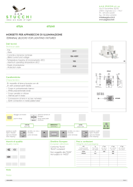
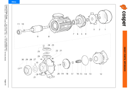
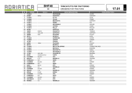
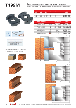
BM F4301: TELAIO TRIANGOLARE PREASSEMBLATO
BM F4301: PREASSEMBLED TRIANGULAR BRACKET
Elementi del telaio triangolare preassemblato
Preassembled triangular bracket components
Dado M8 flangiato BM F4303
Flanged nut M8 BM F4303
Vite testa a martello M8 BM F4004
Hammer-headed screw M8 BM F4004
Rondella
Washer
Dado M8 flangiato BM F4303
Flanged nut M8 BM F4303
Vite M8
Screw M8
Barra di sostegno
Backing bracket
Dado M8 flangiato BM F4303
Flanged nut M8 BM F4303
BM F4301
Vite M8
Screw M8
Rondella
Washer
Montaggio del telaio triangolare preassemblato
Preassembled triangular bracket assembling
Stabilito l’angolo di utilizzo, inserire le viti e serrare con i
dadi flangiati
BM S.p.A. 20089 ROZZANO - MILANO (ITALY) - Via Milano 54/56 Tel.: (+39) 028923911 (r.a) - FAX 028256873
http://www.bm-group.com mailto:[email protected]
BM F4301 10/09 rev0
Once established the angle to be used, insert screws and
screw-up with flanged nuts
BM F4301: TELAIO TRIANGOLARE PREASSEMBLATO
BM F4301: PREASSEMBLED TRIANGULAR BRACKET
La struttura triangolare preassemblata consente il fissaggio su superfici piane con la possibilità di
avere 2 angoli di posizionamento standard di 30°e 35°
Preassembled triangular structure helps fixing on plane surfaces with the possibility to have 2
standard positioning angles of 30° and 35°
Struttura 35°
Structure 35°
¡
Struttura 30°
Structure 30°
¡
Un terzo angolo di 25° è realizzabile eseguendo un taglio della barra di sostegno
It is possible to realize a third angle of 25° by cutting the backing bar
Struttura 25°
Structure 25°
BM S.p.A. 20089 ROZZANO - MILANO (ITALY) - Via Milano 54/56 Tel.: (+39) 028923911 (r.a) - FAX 028256873
http://www.bm-group.com mailto:[email protected]
BM F4301_25° SL 10/09 rev0
Riferimenti per taglio e foratura
Cutting and drilling references
MONTAGGIO TELAIO TRIANGOLARE PREASSEMBLATO SUL PROFILO BM F4001
ASSEMBLING TRIANGULAR BRACKET ON PROFILE BM F4001
D
C
a. Stabiliti i fori di utilizzo per il
fissaggio dei moduli
fotovoltaici, inserire le viti a
testa a martello e avvitare i dadi
flangiati senza serrare.
b. Inserire i dati testa a martello
nella cava inferiore del profilo
BM F4001
c. Serrare il profilo BM F4001
utilizzando i dadi flangiati e una
chiave esagonale da 13 mm
a. Once established the holes
useful for fixing photovoltaic
modules, insert hammer-headed
screws and screw flanged nuts
without tighten
b. Insert hammer-headed nuts in the
lower quarry of profile BM F4001
c. Screw-up profile BM F4001 using
flanged nuts and an hexagonal
wrench of 13 mm
BM S.p.A. 20089 ROZZANO - MILANO (ITALY) - Via Milano 54/56 Tel.: (+39) 028923911 (r.a) - FAX 028256873
http://www.bm-group.com mailto:[email protected]
BM F43 01_1 SL 10/09 rev0
B
BM F4003: COLLEGAMENTO PER PROFILI
BM F4003: PROFILES LINK-UP
Vite TCEI M8x12 / Screw TCEI M8x12
#.'
MONTAGGIO COLLEGAMENTO PER PROFILI BM F4003 SU PROFILO BM F4001
ASSEMBLING PROFILE BM F4003 LINK-UP ON PROFILE BM F4001
a
a.
Posizionare la barra di collegamento del profilo
BM F4003 sui due lati del profilo BM F4001
a.
Position connection bar of profile BM F4003 on
both sides of profile BM F4001
b.
Inserire la barra di collegamento BM F4003 nelle
sedi laterali del profilo BM F4001 e serrare con 2
viti TCEI
b
c
b.
Insert connection bar BM F4003 in the lateral points
of profile BM F4001 and screw-up with 2 screws TCEI
c.
Avvicinare il secondo profilo BM F4001 e serrare le altre 2
viti TCEI della barra di collegamento BM F4003
c.
Bring near the second profile BM F4001 and
screw-up the other 2 screws TCEI of the connection
bar BM F4003
BM S.p.A. 20089 ROZZANO - MILANO (ITALY) - Via Milano 54/56 Tel.: (+39) 028923911 (r.a) - FAX 028256873
http://www.bm-group.com mailto:[email protected]
BM F4003 SL 10/09 rev0
Il collegamento tra profili deve essere utilizzato per giunzioni ad una distanza uguale
o inferiore ad 1/5 dell’interasse di fissaggio
The connection between profiles must be utilized as for junction placed away from a
distance equal or lower to 1/5 of the fixing interaxis
BM F4002: STAFFA DI FISSAGGIO LATERALE
BM F4002: LATERAL FIXING STIRRUP
#.'
a.
Con la staffa di fissaggio laterale BM F4002 possiamo eseguire fissaggi perpendicolari al profilo BM F4001
a.
With the lateral fixing stirrup BM F4002 it is possible to fix perpendicolary to profile BM F4001
BM S.p.A. 20089 ROZZANO - MILANO (ITALY) - Via Milano 54/56 Tel.: (+39) 028923911 (r.a) - FAX 028256873
http://www.bm-group.com mailto:[email protected]
.
BM F4002 SL 10/09 rev0
B
BM F4009: STAFFA DI FISSAGGIO LATERALE
BM F4009: LATERAL FIXING STIRRUP
Vite testa a martello M8x20
Hammer-headed screw M8x20
#.'
Dado flangiato (1)
Flanged nut (1)
Vite TE M8 (3)
Screw TE M8 (3)
Dado testa a martello (2)
Hammer-headed nut (2)
a. Sovrappore i profili BM F4001 e posizionarli in
funzione delle propie esigenze
a. Superimpose profiles BM F4001 and position
them according to own needs
B
b. Inserire nella cava superiore del profilo BM F4001
la vite con il dado testa a martello della staffa di
fissaggio laterale BM F4009
Fissare la staffa laterale BM F4009 al profilo BM F4001
C
b. Insert in the upper quarry of profile BM F4001 the screw
with hammer-headed nut of the lateral fixing stirrup
BM F4009
Fix the lateral stirrup BM F4009 on profile BM F4001
c. Avvicinare il profilo superiore BM F4001 alla staffa di
fissaggio
Inserire la vite testa a martello nell’asola e serrare il tutto
BM S.p.A. 20089 ROZZANO - MILANO (ITALY) - Via Milano 54/56 Tel.: (+39) 028923911 (r.a) - FAX 028256873
http://www.bm-group.com mailto:[email protected]
BM F4009 SL 10/09 rev0
D
c. Bring near the upper profile BM F4001 to the fixing stirrup.
Insert the hammer-headed screw in the buttonhole and
screw- up
MONTAGGIO MORSETTO FINALE SUL PROFILO BM F4001
ASSEMBLING FINAL CLAMP ON PROFILE BM F4001
Vite TCN (3)
Screw TCN (3)
Morsetto MF
Clamp MF
Elementi del morsetto finale
Final clamp elements
Molla
Spring
Rondella (1)
Washer (1)
Dado testa a martello (2)
Hammer-headed nut (2)
BM F 4001
a.
Posizionare il morsetto finale nell’asola superiore del
profilo BM F4001
a.
Position final clamp in the upper buttonhole of
profile BM F4001
b.
Inserire il morsetto finale nell’asola, facendo appoggiare
la rondella (1) sul profilo BM F4001
b.
Insert final clamp in the buttonhole by resting the
washer (1) on profile BM F4001
c.
Premendo e ruotando la vite TCN (3) in senso orario di
90 ° si fa ruotare il dado testa a martello (2) il quale
vincola il morsetto finale al profilo BM F4001
c.
Pressing and 90° rotating screw TCN (3), clockwise, it
makes rotate hammer-headed nut (2) which hold final
clamp to profile BM F4001
B
C
BM S.p.A. 20089 ROZZANO - MILANO (ITALY) - Via Milano 54/56 Tel.: (+39) 028923911 (r.a) - FAX 028256873
http://www.bm-group.com mailto:[email protected]
MF SL 10/09 rev0
D
MONTAGGIO MORSETTO CENTRALE SUL PROFILO BM F4001
ASSEMBLING MIDDLE CLAMP ON PROFILE BM F4001
Vite TCN (3)
Screw TCN(3)
Morsetto MC
Clamp MC
Elementi del morsetto centrale
Middle clamp elements
Molla
Spring
Rondella (1)
Washer (1)
Dado testa a martello (2)
Hammer-headed nut (2)
BM F4001
a. Posizionare il morsetto centrale nell’asola superiore del
profilo BM F4001
a. Position middle clamp in the upper buttonhole
of profile BM F4001
B
b. Inserire il morsetto centrale nell’ asola facendo appoggiare
la rondella (1) sul profilo BM F4001
b. Insert middle clamp in the buttonhole by resting the
washer (1) on profile BM F4001
C
c. Premendo e ruotando la vite TCN (3) in senso orario di
90° si fa ruotare il dado testa a martello (2) il quale
vincola il morsetto centrale al profilo BM F4001
c. Pressing and 90° rotating screw TCN (3), clockwise, it makes
rotate hammer-headed nut (2) which hold middle clamp to
profile BM F4001
BM S.p.A. 20089 ROZZANO - MILANO (ITALY) - Via Milano 54/56 Tel.: (+39) 028923911 (r.a) - FAX 028256873
http://www.bm-group.com mailto:[email protected]
MC SL 10/09 rev0
D
BM F4601-2-3: MONTAGGIO DOPPIO FILETTO SUL PROFILO BM F4001
BM F4601-2-3: ASSEMBLING DOUBLE THREAD ON PROFILE BM F4001
BM F4001
Vite M8
Screw M8
Dado M8
Nut M8
BM F4601-2-3
a.
a.
Elementi di fissaggio per il montaggio del profilo BM F4001
a.
Fixing elements for assembling profile BM F4001
b.
Inserire la vite M8 testa esagonale nella guida inferiore del
profilo di alluminio BM F4001
b.
Insert hexagonal screw M8 in the lower guide of
aluminium profile BM F4001
c.
Posizionare la vite M8 ed inserirla nell’asola situata sulla
parte superiore del nostro BM F4601-2-3
c.
Position screw M8 and insert it in the buttonhole placed on
the upper part of our BM F4601-2-3
b
c
d. Serrare gli elementi con il dado M8
Screw-up elements wit nut M8
d
BM S.p.A. 20089 ROZZANO - MILANO (ITALY) - Via Milano 54/56 Tel.: (+39) 028923911 (r.a) - FAX 028256873
http://www.bm-group.com mailto:[email protected]
BM F4601-2-3 SL 10/09 rev0
d.
BM F4601-2-3: MONTAGGIO DOPPIO FILETTO PER COPERTURA ONDULATA
BM F4601-2-3 : ASSEMBLING DOUBLE THREAD FOR WAVY SURFACES
1. Stabilità la posizione della vite doppio filetto
forare la copertura
1. Once established the position of double thread screw,
pierce the surface
2. Montare le viti doppio filetto con chiave esagonale
da 13 usando i dadi flangiati
2. Assemble double thread screw with 13 hexagonal
wrench using flanged nut
Fare aderire la guarnizione sulla copertura
per evitare infiltrazioni
Make adhere the gasket on the surface in
order to avoid any infiltration
Regolazione fissaggio doppio filetto :
Adjustment of double thread fixing:
b) Avvitare il dado (3) definendo l’intercapedine
tra copertura e piastra (2)
b) Screw-up nut (3) defining the gap between surface and plate (2)
d) Inserire la piastra (2) serrare con il dado (1)
d) Insert plate (2) and tighten with nut (1)
BM S.p.A. 20089 ROZZANO - MILANO (ITALY) - Via Milano 54/56 Tel.: (+39) 028923911 (r.a) - FAX 028256873
http://www.bm-group.com mailto:[email protected]
BM F4601-2-3_1 SL 10/09 rev0
a) Serrare il dado (4)
a) Tighten nut (4)
BM F4401: MONTAGGIO DEL GANCIO REGOLABILE PER TEGOLE
BM F4401: ASSEMBLING ADJUSTABLE HOOK FOR TILE
I ganci vengono avvitati sui traversi inclinati del tetto
Hooks are screwed-up on nodded traverses located on the roof
1. Stabilità la posizione dei ganci BM F4401
rimuovere le tegole necessarie
1. Once established the position of hooks BM F4401
remove necessaries tiles
2. Montare i ganci BM F4401 sui travetti inclinati.
Posizionare la staffa di fissaggio (1)
2. Assemble hooks BM F4401 on nodded traverses.
Position fixing stirrup (1)
Le viti di fissaggio dei ganci devono
essere predisposte in cantiere
Foro passaggio vite Ø 9 mm
Fixing screws have to be predisposed
on construction site
Screw hole: 9 mm
Nella maggioranza dei casi è sufficente
spostare le tegole verso l’alto
In most of the cases, it is sufficient to move
tiles upwards.
8
Regolazione gancio:
Hook adjustment:
a) Posizionare la staffa di collegamento (2) in una delle sedi
quadre.
a) Position connection stirrup (2) in one of the squares
b) Regolare l’altezza della staffa di collegamento (2) con
l’apposita vite (4) e dado (5)
b) Adjust height of connection stirrup (2) with appropriate
screw (4) and nut (5)
c) Regolare altezza staffa di appoggio (3) con apposita vite (7)
e dado (8)
c) Adjust height of backing stirrup (3) with appropriate
screw (7) and nut (8)
Posizionare sempre la staffa di ancoraggio nell’incavo della tegola come in figura B
Always position anchorage stirrup in tile’s hollow as figure B.
BM S.p.A. 20089 ROZZANO - MILANO (ITALY) - Via Milano 54/56 Tel.: (+39) 028923911 (r.a) - FAX 028256873
http://www.bm-group.com mailto:[email protected]
BM F4401_1 SL 10/09 rev0
Fig. B
BM F4401: MONTAGGIO STAFFE SUL PROFILO BM F4001
BM F4401: ASSEMBLING STIRRUP ON PROFILE BM F4001
BM F4001
Vite M8
Screw M8
Dado M8
Nut M8
BM F4401
a. Elementi di fissaggio per il montaggio del profilo BM F4001
a
a. Fixing elements for assembling profile BM F4001
b. Inserire il dado M8 testa esagonale nella guida inferiore del
profilo di alluminio BM F4001
b. Insert hexagonal-headed nut M8 in the lower guide
of aluminium profile BM F4001
b
c. Posizionare la vite M8 ed inserirla nel asola situata sulla
parte superiore della staffa BM F4401
c
Position screw M8 and insert it in the buttonhole
placed on the upper part of stirrup BM F4401
c
d. Serrare gli elementi con il dado M8
d. Tighten elements with nut M8
BM S.p.A. 20089 ROZZANO - MILANO (ITALY) - Via Milano 54/56 Tel.: (+39) 028923911 (r.a) - FAX 028256873
http://www.bm-group.com mailto:[email protected]
BM F4401 SL 10/09 rev0
d
BM F4402: MONTAGGIO DEL GANCIO REGOLABILE PER COPPI
BM F4402: ASSEMBLING ADJUSTABLE HOOK FOR ROOF TILES
I ganci vengono avvitati sui traversi inclinati del tetto
Hooks are screwed-up on nodded traverses located on the roof
1.
Stabilità la posizione dei ganci
BM F4402 rimuovere i coppi necessari
1.
Once established the position of
hooks BM F4402 remove necessaries
roof tiles
2.
Montare i ganci BM F4402
sui travetti inclinati
Assemble hooks BM F4402 on
nodded traverses
2.
Le viti di fissaggio dei ganci devono
essere predisposte in cantiere
foro passaggio vite Ø9 mm
Hooks fixing screws hooks have to be
predisposed on construction site
Screw hole: 9 mm
Nella maggioranza dei casi è sufficiente
spostare i coppi verso l’alto
In most of the cases it is sufficient to
move roof tiles upwards
Regolazione gancio:
Hook adjustment:
a)
a)
Posizionare la staffa di fissaggio (1) sul traversino
Position fixing stirrup (1) on traverse
b)
Regolare altezza staffa di collegamento (2) con apposita
vite (4) e dado (5)
Adjust height of connection stirrup (2) with appropriate
screw (4) and nut (5)
b)
c)
c)
Regolare altezza staffa appoggio (3) con apposita vite (7)
e dado (8)
Adjust height of backing stirrup (3) with appropriate
screew (7) and nut (8)
Posizionare sempre la staffa di ancoraggio nell’incavo della tegola come in figura B
Always position anchorage stirrup in tile’s hollow as figure B.
BM S.p.A. 20089 ROZZANO - MILANO (ITALY) - Via Milano 54/56 Tel.: (+39) 028923911 (r.a) - FAX 028256873
http://www.bm-group.com mailto:[email protected]
BM F4402_1 SL 10/09 rev0
Fig. B
BM F4501: MONTAGGIO DEL MORSETTO PER LAMIERE AGGRAFFATE
BM F4501: ASSEMBLING CLAMP FOR CRIMPED PLATES
Il montaggio del morsetto avviene sulla sporgenza a forma di oliva delle lamiere aggraffate.
Il fissaggio avviene senza foratura.
Assembling clamp has to be done on the olive shaped projection of crimped plates.
Fixing can be done without any drilling.
1. Stabilire la posizione dei morsetti BM F4501
in funzione dell impianto
1. Established the position of clamps BM F4501
according to the system
a)
a)
Posizionare il morsetto su i due lati della lamiera
Position clamp on both side of plate
b)
b)
Inserire le viti (3) nelle apposite sedi quadre
Insert screws (3) on appropriate squares
c)
c)
Serrare i dadi (5)
Screw-up nuts (5)
BM S.p.A. 20089 ROZZANO - MILANO (ITALY) - Via Milano 54/56 Tel.: (+39) 028923911 (r.a) - FAX 028256873
http://www.bm-group.com mailto:[email protected]
BM F4501 SL 10/09 rev0
Montaggio morsetto:
Assembling clamp:
BM F4501: MONTAGGIO STAFFE SUL PROFILO BM F4001
BM F4501: ASSEMBLING STIRRUP ON PROFILE BM F4001
BM F4001
Vite M8
Screw M8
BM F4501
Dado M8
Nut M8
a
a.
a.
Elementi di fissaggio per il montaggio del profilo BM F4001
Fixing elements for assembling profile BM F4001
b.
Inserire il dado M8 testa esagonale nella guida inferiore
del profilo di alluminio BM F4001
Insert hexagonal-headed nut M8 in the lower guide
of aluminium profile BM F4001
b.
b
c.
c
Posizionare la vite M8 ed inserirla nel asola situata sulla
parte superiore della staffa BM F4501
Position screw M8 and insert it in the buttonhole
placed on the upper part of stirrup BM F4501
c
d.
d.
Serrare gli elementi con il dado M8
Tighten elements with nut M8
BM S.p.A. 20089 ROZZANO - MILANO (ITALY) - Via Milano 54/56 Tel.: (+39) 028923911 (r.a) - FAX 028256873
http://www.bm-group.com mailto:[email protected]
BM F4501_1 SL 10/09 rev0
d
Scaricare