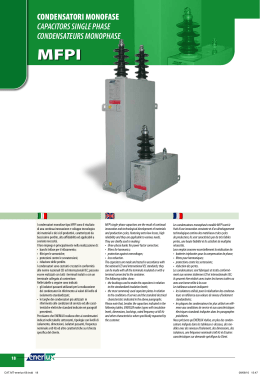
BIORIPHASO REV F _6.qxp
27-01-2012
11:26
Pagina 28
2012
Condensatori per
rifasamento
industriale MT
BIORIPHASO/TF
Il rifasamento migliora
l’efficienza dell’impianto
elettrico, ne riduce
l’impatto ambientale
MV Power
Capacitors
BIORIPHASO/TF
Better efficiency of
electrical system, lower
environmental impact
BIORIPHASO REV F _6.qxp
27-01-2012
11:26
Pagina 1
INDICE / INDEX
Produzione ICAR / ICAR range
Pag. 4
Qualità ICAR / ICAR Quality System
Pag. 6
Soluzioni di Media e Alta tensione / Medium and High Voltage Solutions
Pag. 7
Condensatori / Capacitors BIORIPHASO/TF
BIORIPHASO/TF senza fusibili interni / Without internal fuses
BIORIPHASO/TF con fusibili interni / With internal fuses
BIORIPHASO/TF trifase / three phase
Pag.
Pag.
Pag.
Pag.
Banchi di condensatori / Capacitor banks
Pag. 18
Banchi di condensatori in quadro protetto / Metal enclosed capacitor banks
Pag. 22
Note tecniche / Technical remarks
Pag. 24
Istruzioni di sicurezza e stoccaggio / Safety and storage instructions
Pag. 26
8
13
15
17
BIORIPHASO REV F _6.qxp
27-01-2012
:
11:26
Pagina 2
technology looking ahead
Founded in 1946, ICAR has rapidly reached and constantly
maintained a position that is in the vanguard for the
research and development of new products in the field of
capacitors and components for which capacitors are key
parts.
Since the early 60’s, ahead of its time, ICAR started the
production of metalized polypropylene film capacitors,
developing the metallization by its own in order to have the
whole manufacturing process under control.
Today ICAR Group is leader in the production of Low and
Medium voltage power factor correction capacitors; by its
companies ICAR controls all the manufacturing phases of
the capacitor, core business of the group; from the
polypropylene film/special paper to their metallization, the
production of the finished capacitor, L.V. power factor
correction systems and M.V. banks.
Nowadays ICAR group is made of 6 manufacturing plants
all displaced in Europe and the entire direct control of the
productive chain is the best quality guarantee of the final
product.
Beside M.V capacitors and banks, object of this catalogue,
ICAR produces:
• lighting capacitors;
• motor run capacitors;
• power electronics and special capacitors
• capacitors, banks and passive L.V. and filter
• L.V voltage stabilizers;
• L.V. transformers and chokes.
Fondata nel 1946, ICAR ha rapidamente raggiunto e
costantemente mantenuto una posizione di avanguardia
nella ricerca e nello sviluppo di nuovi prodotti nel campo dei
condensatori e dei componenti per i quali i condensatori
sono una parte fondamentale.
Fin dai primi anni '60, precorrendo i tempi, ICAR iniziò la
produzione dei condensatori in film di polipropilene
metallizzato, sviluppandone in proprio la metallizzazione,
così da avere sotto controllo l'intero processo produttivo.
Oggi ICAR Group è leader nella produzione di sistemi di
rifasamento in Bassa e Media Tensione; controlla con
proprie aziende tutte le fasi produttive del condensatore,
core business del gruppo: dal film in polipropilene/fogli di
carta speciale, alla loro metallizzazione, la realizzazione del
condensatore finito, la produzione dei quadri di rifasamento
BT e dei banchi MT.
Il Gruppo ICAR è oggi costituito da 6 siti produttivi dislocati
tutti in Europa, ed il completo controllo diretto della filiera
produttiva è la miglior garanzia di qualità del prodotto finale.
Oltre ai sistemi di rifasamento MT, oggetto del presente
catalogo, ICAR produce:
• condensatori per rifasamento lampade;
• condensatori per avviamento marcia motori;
• condensatori per elettronica di potenza e speciali;
• condensatori, sistemi di rifasamento e filtri attivi/passivi
bassa tensione;
• stabilizzatori di tensione BT e MT;
• trasformatori ed induttanze.
3
BIORIPHASO REV F _6.qxp
27-01-2012
11:26
Pagina 3
CONDENSATORI PER RIFASAMENTO LAMPADE
LIGHTING CAPACITORS
Qualsiasi soluzione per il rifasamento degli apparecchi illuminanti è realizzabile con le diverse Serie
di Condensatori appartenenti a questa famiglia di prodotto.
Le serie in custodia plastica TYPE A e custodia metallica TYPE B, la molteplicità delle connessioni
e dei sistemi di fissaggio rendono idoneo il condensatore ICAR, adatto sia al rifasamento parallelo
che serie.
I marchi ENEC e UL certificano la conformità dei Condensatori Icar alle norme vigenti e ne
garantiscono la qualità.
The ICAR series of lighting capacitors are suitable for parallel and series power factor correction
applications in both fluorescent and discharge light fittings.
Moreover Plastic Case Type A and Metal Case Type B capacitors can be equipped with a wide range
of fixing devices and termination options.
ENEC and UL approvals certify that ICAR lighting capacitors are in compliance with the latest
standards.
ENEC and UL marking assures the customer of an ICAR product with high levels of quality and
reliability.
CONDENSATORI PER AVVIAMENTO
MARCIA MOTORI
MOTOR RUN CAPACITORS
La gamma di prodotto è la più ampia presente sul mercato e comprende condensatori in film di
polipropilene utilizzabili per i livelli di tensione da 250V a 500V, con aspettativa di vita e di utilizzo
fino a 30.000 ore.
I terminali e gli accessori di fissaggio a catalogo consentono l’utilizzo del Condensatore ICAR in
qualsiasi applicazione.
Il particolare design del condensatore ICAR distingue i ns. componenti per qualità ed affidabilità. I
marchi IMQ, VDE e UL garantiscono la conformità dei Condensatori ICAR alle normative
internazionale.
The ICAR motor run capacitor product range is one of the largest on the market. The polypropylene
film capacitors are available for different levels of voltage from 250V up to 500V with long life
ratings up to 30.000 hours.
The variety of terminations and fixings shown in our catalogue give the possibility to use these
capacitors in any kind of application. The special design of ICAR capacitors distinguish these
components with quality and reliability.
IMQ, VDE and UL approvals guarantee the ICAR motor capacitor range meets with international
standards.
CONDENSATORI PER ELETTRONICA
DI POTENZA E SPECIALI
POWER ELECTRONICS AND SPECIAL CAPACITORS
Condensatori in polipropilene o in carta bimetallizzata per utilizzo come:
• filtro di ingresso lato continua per inverter (serie LNK, BIOENERGY-D)
• filtro lato alternata per inverter e UPS (serie MKP, MKV, BIOENERGY-A)
• Protezione di semiconduttori (serie THY)
• Applicazioni gravose in alternata (serie MKP e BIOENERGY-A)
• Forni ad induzione a media frequenza (serie BIOFURN)
• Applicazioni medicali (serie SP25)
• Condensatori speciali per accumulo di energia
Metallized Polypropylene film and bimetallized paper capacitors for:
• DC link input filters for inverters (LNK and BIOENERGY-D series)
• AC filters for inverters and UPS (MKP, MKV, BIOENERGY-A series)
• Semiconductors snubber applications (THY series)
• Heavy duty AC applications (MKP and BIOENERGY-A series)
• Medium frequency furnaces (BIOFURN Series)
• Medical applications (SP25 series)
• Energy storage applications
4
BIORIPHASO REV F _6.qxp
27-01-2012
11:26
Pagina 4
STABILIZZATORI DI TENSIONE
VOLTAGE STABILISERS
Stabilizzatori elettrodinamici e statici, trifasi e monofasi, BT e MT da 1 a 4000kVA con controllo a
microprocessore.
Condizionatori di linea elettrodinamici, trifasi e monofasi, BT e MT da 1 a 2000kVA con controllo a
microprocessore.
Electrodynamic and static voltage stabilisers, single-phase and three-phase, LV and MV from
1 up to 4000kVA with microprocessor control system.
Electrodynamic line conditioners, single-phase and three-phase, LV and MV from 1 up to 2000kVA
with microprocessor control system.
TRASFORMATORI ED INDUTTANZE
TRANSFORMERS AND CHOKES
Trasformatori elettrici, monofasi e trifasi, BT e MT per isolamento galvanico, UPS e raddrizzatori.
Trasformatori MT per distribuzione e raddrizzatori inglobati in resina.
Reattori-Induttanze-Reattanze, monofase e trifase, BT e MT per rifasamento, di filtro CA/CC.
Single-phase and three-phase MV and LV Electric Transformers for galvanic isolation, UPS and
rectifiers.
Epoxy resin MV Transformers for distribution and rectifiers.
Single-phase and Three-phase MV and LV reactors and chokes for power correction system and
AC/DC filters.
RIFASAMENTO INDUSTRIALE BT
POWER FACTOR CORRECTION SYSTEM
AND HARMONIC FILTERS
Gamma completa di sistemi di rifasamento fissi, standard e con induttanze di blocco armoniche;
filtri passivi e filtri attivi per l’eliminazione delle correnti armoniche.
Tutti i sistemi di rifasamento automatici sono stati sottoposti a test di tipo in laboratori riconosciuti.
Range is complete of fix and automatic LV power factor correction systems, standard and detuned,
active and passive harmonic absorption filters.
All of automatic systems have undergone type tests at International Laboratories.
5
BIORIPHASO REV F _6.qxp
27-01-2012
11:26
Pagina 5
ICAR MEANS CAPACITORS!
ICAR È IL CONDENSATORE, SICURO!
ICAR SpA è dal 1946 sinonimo di condensatore, coniugato nelle sue
molteplici applicazioni.
Da sempre ICAR crede nella qualità dei suoi prodotti e nella forza delle
normative internazionali per l’ottenimento degli elevati standard
prestazionali richiesti al condensatore per applicazioni industriali.
ICAR è oggi una delle poche aziende in grado di produrre condensatori
partendo dalla materia prima e arrivando fino al prodotto finito: tutto il
processo è controllato per ottenere un prodotto con elevato livello
qualitativo, che garantisce il funzionamento anche nelle configurazioni
impiantistiche più gravose.
ICAR produce oggi differenti tipologie di condensatori, da quelli per
rifasamento lampade e motori monofasi a quelli per elettronica di potenza
(trazione elettrica, azionamenti industriali), a quelli di media tensione.
Le peculiari caratteristiche richieste a questi prodotti in termini di
sollecitazioni elettriche, meccaniche e termiche hanno permesso di trovare
soluzioni tecniche che poi hanno avuto interessanti applicazioni anche in
altri ambiti: ad esempio l’ottimizzazione dei condensatori per applicazioni
speciali ha permesso di individuare soluzioni molto robuste che sono state
poi applicate ai condensatori di rifasamento.
La realizzazione del film dielettrico (polipropilene o carta speciale), il
processo di metallizzazione, la realizzazione del condensatore e la
costruzione del quadro di rifasamento sono eseguiti integralmente in
aziende del Gruppo: questo garantisce l’ottenimento dei più alti standard
qualitativi sia del film metallizzato che, di conseguenza, dei condensatori
prodotti.
Inoltre, il know how acquisito in quasi 50 anni nella realizzazione del film
metallizzato ha permesso ad ICAR di realizzare prodotti assolutamente
innovativi, quali i condensatori della gamma 3Ut.
ICAR SpA is synonym of capacitor from 1946, conjugated over its multiple
applications.
All along ICAR has been believing in the quality of its products and in the
strength of the International regulations for the achievements of the high
performance standards required for capacitor in industrial applications.
Nowadays ICAR is one of the few companies able to manufacture
capacitors starting from the raw material up to the finished product; the
entire process is checked in order to obtain a product of high quality level
that guarantees its functioning even in the most burdensome plant
configurations.
Today ICAR produces different type of capacitors, from the lighting and
single phase motor types to the ones for power electronics (electric
traction, industrial services) and those of medium voltage.
The various characteristics demanded to these products in terms of
electric, mechanical and thermal stress, enabled to find technical solutions
that have been applying in other fields with interesting results: for instance
the optimization of capacitors for special applications enabled to find very
strong solutions that have been then applied on power factor correction
capacitors.
The production of the dielectric film (polypropylene or special paper), the
metallization process, the production of the capacitor and the construction
of the power factor correction banks are fully executed within companies
of the Group; that guarantees the achievement of the highest quality
standard weather of the metalized film or, consequently, the capacitors
manufactured.
Furthermore, the know how acquired in almost 50 years of metalized film
production, has enabled ICAR to realize absolute innovative products like
3Ut range of capacitors.
Abituata ad operare sui mercati internazionali, ICAR si è confrontata con le
richieste degli enti certificatori più severi, ed è certificata
UNI EN ISO 9001: 2009.
Used to deal with International markets ICAR faced the requests of the
most strict Certification Bodies and was awarded UNI EN ISO 9001: 2008
Certification.
ICAR partecipa regolarmente ai comitati CEI per la redazione delle norme
di prodotto, finalizzate all’ottenimento di criteri oggettivi per valutare le
prestazioni e la sicurezza dei condensatori.
E’ costantemente all’avanguardia ed in grado di anticipare le richieste
normative; per verificare la rispondenza alle norme internazionali ed ai
criteri di accettazione dei clienti più severi, i
prodotti e le apparecchiature ICAR sono
sottoposti a prove sia nei laboratori interni (dove
è possibile provare condensatori fino a 700 µF, e
fino alla tensione di 80 kV) che nei laboratori più
all’avanguardia e internazionalmente riconosciuti
(CESI).
ICAR periodically takes part to CEI (Italian Ectrotechnical Commission) for
the compilation of the product regulations, aimed at setting the objective
criterions to evaluate capacitors performances and safety.
It’s constantly in the vanguard and able to anticipate the regulations
requirements; in order to ensure the accordance with the International
regulations and the most strict customers
acceptance criterions, products are submitted
to tests in the internal laboratories (where it’s
possible to test capacitors up to 700 µF and
voltage up to 80 kV) and in the greatest
internationally recognized vanguard laboratories
(CESI).
Il tutto a garanzia della sicurezza del cliente, che
si affida ad un partner serio e con una
esperienza pluridecennale nella produzione dei
condensatori per le applicazioni più disparate.
Everything is performed for the safety of the
customer who entrusted a reliable partner with
a pluridecennal experience in capacitors
production for the most disparate applications.
6
BIORIPHASO REV F _6.qxp
27-01-2012
11:26
Pagina 6
SOLUZIONI DI MEDIA ED ALTA TENSIONE
MEDIUM AND HIGH VOLTAGE SOLUTIONS
ICAR propone una gamma completa per il rifasamento ed il filtraggio delle armoniche in Media ed Alta Tensione:
ICAR offers numerous solutions for power-factor correction
and filtering of harmonics in Medium and High Voltage:
Condensatori monofasi
• potenze nominali unitarie fino a 800kvar
• per reti con tensione nominale fino a 36kV
• frequenza di 50 o 60Hz.
Single phase capacitors
• unit power up to 800kvar
• nominal voltages up to 36kV
• frequency of 50 or 60Hz.
Condensatori trifasi
• potenze nominali unitarie fino a 600kvar
• per reti con tensione nominale fino a 24kV
• frequenza di 50 o 60Hz.
Three-phase capacitors
• nominal unit power up to 600kvar
• nominal voltages up to 24kV
• frequency of 50 or 60Hz.
Condensatori speciali per applicazioni custom quali
ad esempio:
• trifasi con neutro accessibile
• monofasi con collegamento interno a doppia sezione
• di protezione da sovratensioni (usati tipicamente nella protezione di grosse macchine elettriche)
• per applicazione in ambienti con caratteristiche fuori standard
(temperatura elevata o molto bassa, atmosfera salina, altitudine oltre i 1000m, etc)
Special capacitors for customized applications, such
as for example:
• three-phase with neutral brought out
• split-phase capacitor
• for overvoltage protection (typically used in protection of large
electrical machines)
• for applications in environments with abnormal characteristics
(such as high or very low temperature, salty atmosphere, altitude above 1000 m, etc.)
Banchi di rifasamento MT e AT
• potenze fino a 100Mvar
• per reti con tensione nominale fino a 220kV
• frequenza di 50 o 60Hz
MV and HV power-factor correction banks
• powers up to 100Mvar
• voltages up to 220kV
• frequency of 50 or 60Hz
Banchi di assorbimento accordati
• frequenza di accordo dalla 2a alla 13a
• potenze fino a 100Mvar
• reti con tensione fino a 150kV
• frequenza di 50 o 60Hz
Tuned Capacitor banks
• Tuned on harmonics from the 2nd to the 13th
• power up to 100Mvar
• voltage up to 150kV
• frequency of 50 or 60Hz
Filtri speciali MT e AT
• Filtri passa alto, filtri del secondo ordine con doppio accordo,
con resistenza di smorzamento, etc.
MV and HV special filters
Such as high pass, second order filters with double tuning
frequency, damping resistor, etc.
ICAR ha un’esperienza di oltre 60 anni in forniture di soluzioni
per realtà industriali caratterizzate da complesse problematiche
di rifasamento e di filtraggio armonico (acciaierie, cartiere, forgiature, cementifici) in tutto il mondo (Arabia Saudita, Russia,
Hong Kong, Cina, Grecia, Francia, Argentina, Brasile, ...).
Le soluzioni ICAR sono di riconosciuta efficacia, robustezza ed
elevata affidabilità.
ICAR has over 60 years experience supply of products to
industries characterized by complex power factor correction and
harmonic filtering situations (steel mills, paper mills, forging,
cement factories) around the world (Saudi Arabia, Russia, Hong
Kong, China, Greece, France, Argentina, Brazil, etc.).
ICAR solutions are proven of effectiveness, robustness and high
reliability.
7
BIORIPHASO REV F _6.qxp
27-01-2012
11:26
Pagina 7
CONDENSATORI MT BIORIPHASO/TF
BIORIPHASO/TF MV POWER CAPACITORS
CARATTERISTICHE GENERALI
GENERAL FEATURES
Capacitors of the BIORIPHASO/TF type series constitute a complete range for making of solutions for power-factor correction in
MV and HV.
They are designed and manufactured using the most modern
technologies: ensuring long expected life and high reliability.
The BIORIPHASO/TF series is in compliance with applicable
standards (IEC 60871, ANSI, IEEE 18, NEMA CP-1, etc.): they
are therefore suitable for installation in any environment or conditions described in the above standards.
On request, we can, nevertheless, provide capacitors with special characteristic or tested as specified by the customer.
La serie BIORIPHASO/TF costituisce una completa gamma di
modelli di condensatori per la realizzazione di sistemi di rifasamento e filtraggio armonico in MT e AT.
I condensatori della serie BIORIPHASO/TF sono progettati e
costruiti secondo le più moderne ed avanzate tecnologie che ne
garantiscono una lunga vita e un’elevata affidabilità.
I condensatori della serie BIORIPHASO/TF soddisfano le prescrizioni delle norme IEC 60871, ANSI, IEEE 18, NEMA CP-1 e
sono adatti ad essere installati in qualsiasi condizione ambientale e di esercizio prevista da queste norme.
A richiesta possono essere forniti condensatori con caratteristiche speciali o possono essere sottoposti a prove particolari non
contemplate da queste norme.
Classification
The various models are identified by
- series name
- power
- voltage
- typology
- single-phase: with or without internal fuses, with single or
double isolator;
- three-phase: with delta or star connection with neutral
brought out
Classificazione
I vari modelli sono identificati da
- nome della serie
- potenza
- tensione
- tipologia
- monofase: con o senza fusibili interni, con un solo isolatore;
- trifase: con collegamento a triangolo o stella con neutro
accessibile
Example:
BIORIPHASO/TF 200/12:
single-phase capacitor of 200kvar at 12kV,
Esempi
BIORIPHASO/TF 200/12:
condensatore monofase da 200 kvar a 12 kV,
BIORIPHASO/TF 200/12/E:
as above, but with only one bushing;
BIORIPHASO/TF 200/12/E:
come sopra, ma con un solo isolatore
BIORIPHASO/TF 200/12/T:
three-phase capacitor of 200kvar at 12kV
BIORIPHASO/TF 200/12/T:
condensatore trifase da 200 kvar a 12 kV
All capacitors are uniquely identified by the relevant plate as
required by the IEC Standard 60871-1:
Tutti i condensatori sono univocamente identificati dalla targa
esplicativa come prescritto dalla norma IEC 60871 - 1:
•
•
•
•
•
•
•
•
•
•
•
•
•
•
•
•
•
•
•
•
•
•
Nome del costruttore
Numero di matricola/anno
Potenza nominale
Tensione nominale
Frequenza nominale
Classe di temperatura
Livello d’isolamento
Dispositivo di scarica interno
Simbolo del collegamento
Nome dell’ impregnante
Indicazione della presenza fusibili interni
BIORIPHASO/TF
/
Name of manufacturer
Serial number/year
Nominal power
Nominal voltage
Nominal frequency
Temperature category
Insulation level
Internal discharge device
Connection symbol
Name of the impregnating fluid
Indication of the presence of internal fuses (if included)
/
E = se monofase: con un solo isolatore / if single phase: with one bushing
FI = con fusibili interni / with internal fuses
T = trifase / three phase
= tensione nominale, in kV / rated voltage, in kV
= potenza nominale, in kvar. Se la potenza è composta da due addendi, il condensatore
è a doppia sezione /
rated power, in kvar. If Power is shown in two addends, capacitors is split phase type.
8
BIORIPHASO REV F _6.qxp
27-01-2012
11:26
Pagina 8
CARATTERISTICHE COSTRUTTIVE
CAPACITOR CONSTRUCTION
Dielettrico
Dielettrico ed armatura costituiscono la parte più importante del
condensatore, quella che ne determina le caratteristiche elettriche (capacità, perdite) e ne influenza la durata e l’affidabilità nel
tempo.
Dielectric
Dielectric and electrodes constitute the most important parts of the
capacitor, which determines the electrical characteristics (capacity,
losses) and affects the durability and reliability over the time.
The dielectric of BIORIPHASO/TF capacitors is of the all film type, that
is, it is composed of several layers of rough BOPP film (Biaxial Oriented
Polypropylene) of very high quality.
Il dielettrico dei condensatori BIORIPHASO/TF è di tipo tutto film
cioè costituito da più strati di film di polipropilene BOPP (Biaxial
Oriented Polypropylene) rugoso e di elevata qualità.
ICAR has its own factory of BOPP for capacitors that allows to have
complete control of the production chain.
ICAR possiede un suo proprio sito di produzione di film di BOPP
per condensatori, esercitando così un completo controllo della
catena produttiva.
Armature
Le armature dei condensatori BIORIPHASO/TF sono realizzate
da un sottile foglio di alluminio purissimo, per garantire le migliori performance e la più elevata affidabilità.
L’avvolgimento è ad armature sporgenti: assicura una elevata
capacità di tenuta ai picchi di corrente conseguenti i transitori
d’inserzione dei condensatori o durante i transitori dovuti a perturbazioni di rete.
Il risvolto dei bordi assicura una migliore distribuzione del campo
elettrico in queste regioni, conferendo al condensatore una più
elevata resistenza alle sovratensioni e all’innesco delle scariche
parziali.
Aluminium electrodes
The electrodes of BIORIPHASO/TF capacitors are made of a thin sheet
of purest aluminium to ensure the best performance and greatest
reliability.
The winding with the extended foils provides high withstand capacity at
current peaks consequent to the transients of the capacitors switching
or during the transients relating to network fluctuations.
The folded edge ensures a better distribution of the electric field in
these regions, providing the capacitors with higher resistance to
overvoltage and to prevent the partial discharges.
Olio impregnante
I condensatori BIORIPHASO/TF sono impregnati sottovuoto
con fluido ad alta rigidità dielettrica e sono sigillati senza battente d’aria.
L’olio impregna tutti i singoli elementi capacitivi di cui il condensatore è composto e ne riempie tutto il volume libero, assicurando il perfetto isolamento e l’assenza di scariche parziali.
Impregnation oil
BIORIPHASO/TF capacitors are vacuum impregnated with dielectric
fluid and are sealed without an air head. The oil impregnates all the
individual capacitive elements of which the capacitor is composed, and
it fills the entire free volume, ensuring perfect isolation and absence of
partial discharges.
Particolare cura viene posta nelle diverse fasi del trattamento.
Il processo d’essiccazione viene eseguito mantenendo il condensatore in autoclave sotto vuoto ad alte temperature.
Alla fine del processo, all’interno dei condensatori si raggiunge il
vuoto molecolare.
Special attention is paid to the various stages of treatment.
Drying is carried out with the capacitor placed in a vacuum autoclave at
a high temperature.
At the end of the drying process, the interior of the capacitors reaches
the molecular vacuum.
Per l’impregnazione dei condensatori BIORIPHASO/TF viene utilizzato BIOIL®: un olio sintetico biodegradabile, ecocompatibile
(esente da PCB e da altre sostanze pericolose per l’ambiente) e
non tossico.
L’olio, prodotto da primarie aziende chimiche, viene ulteriormente raffinato in ICAR mediante degassificazione sottovuoto e
depurazione chimica.
Rigorosi controlli delle sue caratteristiche fisico-chimiche sono
eseguiti prima dell’impregnazione.
BIOIL® is used for the impregnation of BIORIPHASO/TF capacitors: it is
a biodegradable, environmentally friendly synthetic oil (free of PCBs and
other substances harmful to the environment) and it is non-toxic. The
high quality oil, produced by leading chemical companies, is further
refined at ICAR through vacuum degasification chemical purification.
Rigorous controls of its physical and chemical properties are made prior
to impregnation.
9
BIORIPHASO REV F _6.qxp
27-01-2012
11:26
Pagina 9
Dielectric losses and total losses
Dielectric losses in BIORIPHASO/TF are very low, initially below
0.07 W/kvar, reducing in less than 100 hours of work to a value
in the range between 0.02 to 0.04W/kvar.
Perdite dielettriche e perdite totali
Le perdite dielettriche nei BIORIPHASO/TF sono molto basse,
inizialmente inferiori a 0.07 W/kvar, e si riducono in meno di 100
ore di lavoro ad un valore compreso nell’intervallo 0.02- 0.04
W/kvar.
Dielectric losses must be added to those of the discharge resistances built into the capacitors. BIORIPHASO/TF total losses,
dielectric losses + loss of discharge resistance are:
Alle perdite dielettriche si devono aggiungere quelle delle resistenze di scarica incorporate nei condensatori: le perdite totali,
perdite dielettriche + perdite delle resistenze di scarica, nei condensatori BIORIPHASO/TF sono generalmente:
- less than 0.13 W/kvar for models with discharge resistance
designed to ensure a residual voltage less than at 75V within
10 minutes (IEC standards)
- inferiori a 0.13 W/kvar per i modelli con resistenze di scarica
atte a garantire una tensione residua inferiore a 75 V in 10
minuti (norma IEC)
- less than 0.18 W/kvar for models with discharge resistance
designed to ensure a residual voltage less than 50 V within 5
minutes (IEEE standards).
- inferiori a 0.18 W/kvar per i modelli con resistenza di scarica
atte a garantire una tensione residua inferiore a 50 V in 5 minuti (norma IEEE).
Custodia
La custodia ermeticamente sigillata protegge la parte attiva
(armature e dielettrico), assicurandone la conservazione e il
buon funzionamento nel tempo.
Housing
The hermetically sealed housing protects the active part (electrodes and dielectric), ensuring preservation and good function
over time.
La custodia dei condensatori BIORIPHASO/TF è realizzata in
lamiera di acciaio inossidabile AISI 409, di elevato spessore, piegata e saldata a T.I.G. Il processo di saldatura completamente
automatizzato garantisce un’elevata qualità della saldatura e
quindi la robustezza e l’ermeticità del condensatore.
L’elasticità delle superfici della custodia assicura l’assorbimento
delle dilatazioni termiche dell’olio dovute alla variazione della
temperatura ambiente. Alle basse temperature l’elasticità della
custodia deve assicurare che all’interno non si formi una depressione che riduca la rigidità dielettrica dell’olio e la tensione d’innesco delle scariche parziali. Alle alte temperature viceversa
l’elasticità della custodia deve assicurare che la sovrapressione
interna non assuma valori troppo elevati.
The housing of BIORIPHASO/TF capacitors is made of AISI 409
stainless steel sheet, very thick, bent and T.I.G. welded. The
completely automated process guarantees the highest welding
quality and thus the robustness and hermetic sealing of the
capacitor.
The elasticity of the larger surfaces of the housing ensures that
it follows the thermal expansion of oil due to the variation of
room temperatures. At low temperatures the elasticity of the
housing must ensure that there will not be an inner depression
that reduces the dielectric strength of the oil and the voltage of
partial discharges. At high temperatures, conversely, the elasticity of the housing must ensure that the internal overpressure be
limited.
La custodia è protetta con 2 strati di vernice sintetica adatta al
servizio esterno, che offre un’elevata resistenza meccanica e un
ottimo comportamento in ambiente inquinato da fumi industriali
e da nebbia salina.
Il colore blu-grigio RAL 7031 consente un’efficiente trasmissione del calore con l’ambiente.
Per applicazioni esposte ad elevato irraggiamento solare si utilizza una colorazione più chiara, grigio chiaro RAL 7035, che
permette una maggiore riflessione della radiazione solare limitando il surriscaldamento interno.
The housing is protected with two layers of synthetic paint suitable for outdoor service and having a high mechanical strength
and excellent performance in an environment polluted by industrial fumes and fog.
The blue-gray colour, RAL 7031, allows for efficient transmission
heat within the environment.
For applications exposed to high solar radiation, a lighter gray
colour, RAL 7035, is used which provides for an increased
reflection of solar radiation, limiting internal overheating.
The housing also has two handles for lifting and fixing the capacitor. For specific needs, the positioning of the handles can be
changed on request, or additional handles can be included.
La custodia è dotata di due maniglie per il sollevamento e il fissaggio del condensatore. Per esigenze specifiche la posizione
delle maniglie può essere modificata a richiesta o possono essere previste maniglie aggiuntive.
10
BIORIPHASO REV F _6.qxp
27-01-2012
11:26
Pagina 10
Isolatori
Gli isolatori dei condensatori BIORIPHASO/TF sono realizzati in
porcellana di prima qualità, di colore marrone, a richiesta per
grandi lotti è possibile fornire isolatori di colore grigio chiaro.
Bushing
The bushing of the BIORIPHASO/TF capacitors are made of the
highest quality porcelain, brown in colour; for large lots, it is
possible to provide bushing in a light gray colour, upon request.
Gli isolatori ceramici hanno una elevata resistenza all’arco elettrico e al tracking (particolarmente pericoloso negli ambienti industriali altamente inquinati), sono resistenti agli agenti chimici, agli
agenti atmosferici, al calore, ai funghi e ai batteri, e sono meccanicamente molto robusti.
Gli isolatori ceramici sono perciò una scelta di qualità per i condensatori BIORIPHASO/TF.
Prima del montaggio tutti sono sottoposti a rigorosi controlli.
The porcelain bushings have a high resistance to electrical arcs
and to tracking (especially dangerous in highly polluted industrial
environments); they are resistant to chemicals, atmospheric
agents, heat, fungi and bacteria and are mechanically very
robust.
The porcelain bushings are, therefore, a quality choice for
BIORIPHASO/TF capacitors.
Before assembling, all the
controls.
Gli isolatori dei modelli normalizzati sono adatti per l’installazione
in ambiente con moderata presenza di nebbia o fumi industriali.
Per ambienti eccezionalmente inquinati vengono forniti isolatori
speciali con linee di fuga fino a 31 mm/kV.
bushings are subjected to strict
The bushings of standardized models are suitable for installation
in places with moderate fog or industrial fumes.
For exceptionally polluted (salty or desert-like environments),
special bushings are provided with creepage distance of up to
31 mm/kV.
I condensatori BIORIPHASO/TF monofase vengono forniti con
uno o due isolatori; gli esemplari trifase vengono forniti con tre o
quattro isolatori (in quest’ultimo caso il collegamento interno del
condensatore è a stella con centro stella accessibile).
The BIORIPHASO/TF capacitors are supplied with 1 or 2
bushing; the three-phase version are with 3 bushings or 4 (in the
latter case, the internal connection of the capacitor is star with
neutral brought out).
Resistenze di scarica
Quando i condensatori vengono disconnessi dalla rete rimangono carichi e, in caso di contatto accidentale, l’energia immagazzinata risulterebbe letale. Per questo i condensatori di rifasamento sono dotati di resistenze di scarica incorporate che ne
assicurano la scarica in un tempo prefissato.
Discharge resistance
When the capacitors are disconnected from the network, they
remain charged, and the stored energy would be fatal in case of
accidental contact, so the power-factor correction capacitors
have an incorporated discharge resistor which ensures capacitor discharge in a fixed time.
11
BIORIPHASO REV F _6.qxp
27-01-2012
11:26
Pagina 11
Le resistenze di scarica incorporate nella serie BIORIFASO/TF
assicurano, in accordo con le norme IEC, una riduzione della tensione di carica residua a 75 V in un tempo inferiore a 10 minuti.
In accordance with IEC standards, the incorporated discharge
resistor in BIORIFASO/TF series ensures a reduction of the residual voltage to 75V in less than 10 minutes.
A richiesta, in accordo con le norme IEEE, possono essere previste resistenze per scarica a 50 V in un tempo inferiore a 5 minuti.
On request, in accordance with IEEE standards, discharge resistance at 50V in less than 5 minutes can be provided.
Nota importante per la sicurezza
La presenza delle resistenze di scarica non esime dall’obbligo
della messa in cortocircuito e a terra dei terminali dei condensatori prima di ogni possibile contatto e prima di movimentarli.
I condensatori devono essere immagazzinati con i terminali in
corto circuito.
Important Safety Notice
Notwithstanding the presence of the discharge resistor, it is
mandatory to short circuit and earthing terminals of the capacitors before any possible contact or handling.
Capacitors shall be also stored with short circuited terminals.
Prove di collaudo, di tipo e speciali
ICAR sottopone tutti i condensatori BIORIPHASO/TF alle prove
di collaudo previste dalla norma IEC 60871 e ne rilascia certificazione.
Il laboratorio ICAR è attrezzato per eseguire tutte le prove di collaudo, le prove di tipo e le prove speciali previste dalle norme IEC
60871.
Routine tests, type test and special test
ICAR subjects all BIORIPHASO/TF capacitors to all routine tests
required by IEC standards 60871 and it issues relevant certificates.
The HV laboratory of ICAR is equipped to perform all routine
tests, type tests and the special tests as foreseen for by IEC
60871.
Prove di collaudo:
Misura della capacità (IEC 60871-1, art. 7)
Misura della tangente dell’angolo di perdita (tanδ) del condensatore (IEC 60871-1, art. 8)
Prova di tensione tra i terminali (IEC 60871-1, art. 9)
Prova di tensione in corrente alternata fra i terminali e il contenitore (IEC 60871-1, art. 10)
Prova del dispositivo di scarica interno (IEC 60871-1, art. 11)
Prova di ermeticità (IEC 60871-1, art. 12)
Prova di scarica sui fusibili interni ove presenti (IEC 60871-4, art.
5.1.1)
Routine tests:
Capacitance measurement (IEC 60871-1, art. 7)
Measurement of the tangent of the loss angle (tanδ) of test
capacitor (IEC 60871-1, art. 8)
Voltage test between terminals (IEC 60871-1, art. 9)
AC voltage test between terminals and container (IEC 60871-1,
art. 10)
Test of internal discharge device (IEC 60871-1, art. 11)
Sealing test (IEC 60871-1, art. 12)
Discharge test on internal fuses (IEC 60871-4, art 5.1.1)
Prove di tipo
Prova di stabilità termica (IEC 60871-1, art. 13)
Misura della tangente dell’angolo di perdita (tanδ) del condensatore a temperatura elevata (IEC 60871-1, art. 14)
Prova di tensione in corrente alternata fra i terminali e il contenitore (IEC 60871-1, art. 15)
Prova di tensione ad impulso atmosferico tra i terminali ed il contenitore (IEC 60871-1, art. 16 )
Prova di scarica in cortocircuito (IEC 60871-1, art. 17)
Prova di interruzione dei fusibili interni (IEC 60871-4, art. 5.3)
Type Test
Thermal stability test (IEC 60871-1, art. 13)
Measurement of the tangent of the loss angle (tanδ) of the
capacitor at elevated temperature (IEC 60871-1, art. 14)
AC voltage test between terminals and container (IEC 60871-1,
art. 15)
Lightning impulse voltage test between terminals and container
(IEC 60871-1, art. 16)
Short circuit discharge test (IEC 60871-1, art. 17)
Disconnecting test on internal fuses (IEC 60871-4, art. 5.3)
Prove speciali
Prova di invecchiamento (IEC 60871-2 - art 2.1.4)
Prova di resistenza alle sovratensioni (IEC 60871-2 - art. 2.1.3)
Special tests
Ageing test (IEC 60871-2, art. 2.1.4)
Overvoltage cycling test (IEC 60871-2, art. 2.1.3)
12
BIORIPHASO REV F _6.qxp
27-01-2012
11:26
Pagina 12
BIORIPHASO/TF MONOFASE
BIORIPHASO/TF SINGLE PHASE
ICAR produce condensatori monofase di due tipi:
- senza fusibili interni
- con fusibili interni.
Internamente i condensatori MT sono realizzati collegando in
serie diversi gruppi di elementi in parallelo (vedi fig 1).
Nei condensatori con fusibili interni, in serie a ciascun elemento è
collegato un fusibile che in caso di perforazione lo disconnette
immediatamente (vedi fig 2).
Il condensatore può comunque rimanere in servizio con una piccola riduzione di potenza. Nei condensatori senza fusibili interni
la perforazione di un elemento mette in corto circuito l’intero
gruppo serie a cui l’elemento appartiene, e il condensatore rimane in servizio con un guasto interno.
La scelta della tipologia del condensatore dipende dalle scelte
del progettista della batteria, dalla sua potenza e dalla tensione della rete.
ICAR makes two types of single phase capacitors:
- without internal fuses
- with internal fuses.
MV capacitors are internally made by connecting in series a
number of parallel element groups (see picture 1).
In the capacitors with internal fuses, there is a fuse in series to
each element which melts and isolates the same in case of dielectric perforation: so capacitors can keep on service with a
small output reduction (see picture 1).
In case of capacitors without internal fuses the element perforation short circuits the entire series group at which it belongs, and
the capacitors keep on service with an inner fault.
The choice of capacitors types depends on bank designer
choice and on its power and rated voltage.
BIORIPHASO/TF SINGLE PHASE (without internal
fuses)
BIORIPHASO/TF MONOFASE senza fusibili interni
Small capacitors banks (up to 600 kvar) are made with single
phase capacitors without internal fuses, they are connected in
delta and protected by means of HRC limiting current fuses.
Capacitors banks of higher power (from 600kvar to 1500kvar)
are made up of at least six single phase capacitors or three splitphase, without internal fuses, with capacitor bank connected in
insulated double star and unbalance protection.
In case of capacitors without internal fuses, higher power capacitor banks use one single external expulsion fuse for each capacitor; this fuse, which is specific for power capacitors, is very
easy and effective, and it allows an immediate evidence of faulty capacitor.
In these type of banks the number of capacitors is chosen so to
allow the bank to keep on service even in the case one capacitor has been insulated by its fuse melting. An unbalance protection, which works out a lower priority protection, will provide the
capacitor bank disconnection after a certain number of capacitors are out of order.
Le batterie più piccole (fino a 600 kvar) sono realizzate con tre
unità monofase senza fusibili interni collegate a triangolo e protette con fusibili di tipo HRC limitatori di corrente.
Le batterie delle taglie immediatamente superiori (da 600 kvar a
1500 kvar) sono normalmente realizzate con sei unità monofase
o tre unità monofase a doppia sezione, senza fusibili interni, con
collegamento della batteria a doppia stella isolata con protezione a squilibrio di corrente fra i due centri-stella.
Con condensatori senza fusibili interni si realizzano batterie di
maggiore potenza utilizzando a protezione di ciascun condensatore fusibili del tipo ad espulsione; questo è un tipo di fusibile specifico per condensatori, molto semplice ed efficace, che permette di avere una immediata indicazione visiva dell’unità guasta.
In questo tipo di batterie il numero di unità è scelto in modo tale
che la batteria possa rimanere in servizio anche nel caso una
unità sia stata isolata dall’intervento del proprio fusibile. Una protezione di squilibrio, che svolge la funzione di protezione di
secondo livello, provvederà alla disconnessione della batteria
dopo l’intervento di un certo numero di fusibili.
Capacitors without internal fuses, which have smaller losses
than those with internal fuses, are designed to lower dielectric
withstand and are so much more robust and reliable.
I condensatori senza fusibili interni, che hanno perdite inferiori a
quelli che ne sono dotati, sono progettati con una sollecitazione
dielettrica più bassa e risultano perciò altrettanto robusti ed affidabili.
I condensatori monofase senza fusibili interni sono costruiti in
unità ciascuna di potenza compresa tra 50 e 500 kvar, con tensione nominale tra 1.5 kV e 25 kV.
Single phase without internal fuses capacitors are made in units
of power ranging from 50 to 500 kvar, and with rated voltage
from 1.5 kV to 25 kV.
FIG. 1 / Picture 1
13
FIG. 2 / Picture 2
BIORIPHASO REV F _6.qxp
27-01-2012
Potenza
Power
Tensione
Voltage
(kvar)
(kV)
11:26
50
Pagina 13
Peso
Weight
Dimensioni / Dimensions (mm)
L
P
H
350
140
350
N
M
kg
180
170
100
14
140
270
100
100
21
140
100
29
140
100
34
200
165
39
HB isolatori/Bushing
4.16/√3 - 4.16
100
6.6/√3 - 6.6
fino a / up to
75 kV BIL
180
150
10/√3
350
175
310
200
10.5/√3
350
175
380
250
11/√3
15/√3
350
190
420
300
20/√3
22/√3
350
190
490
200
165
47
400
30/√3
33/√3
350
190
620
200
165
57
350
190
760
200
165
71
500
fino a /up to
125 kV BIL
318
CONDIZIONI DI SERVIZIO / OPERATING CONDITIONS
Classe di temperatura / Temperature class -40/B
Installazione: interna/esterna / Use: indoor/outdoor
Altitudine massima / Altitude a.s.l.: 1000 m
Frequenza / Frequency: 50/60 Hz
Livello di isolamento / Insulating Voltages
Tensione
Tensione
Tensione di
massima
di tenuta a
tenuta ad
del sistema frequenza industriale
impulso
Highest system
Short time
Lighting impulse
Voltage
withstand voltage
voltage test
(kV)
(kV)
(kV)
3.6
10
40
7.2
20
60
12
28
75
17.5
38
95
24
50
125
Ø
Isolatori / Bushings
Livello di isolamento / Voltage levels: 12/28/75 kV
Linea di fuga / Creepage distance > 255 mm
Livello di isolamento / Voltage levels: 24/50/125 kV
Linea di fuga / Creepage distance > 600 mm
Altre potenze e tensioni a richiesta /
Other voltages and powers available upon request
BIL 75 kV
14
BIL 125 kV
BIORIPHASO REV F _6.qxp
27-01-2012
11:26
Pagina 14
BIORIPHASO/TF MONOFASE con fusibili interni
BIORIPHASO/TFSINGLE PHASE with internal fuses
Come accennato in precedenza, in questi condensatori ad ogni
elemento interno è collegato in serie un fusibile. (vedi fig. 2)
Nel caso di perforazione di un elemento il suo fusibile fonde, per
effetto dell’energia di scarica degli elementi connessi in parallelo,
isolandolo.
Il tempo di intervento del fusibile è di poche decine di microsecondi: le altre protezioni non hanno tempo di intervenire e il condensatore rimane in servizio con una piccola riduzione di potenza.
L’elevata affidabilità di questa soluzione permette di dimensionare
condensatori con più alto stress dielettrico e di realizzare unità di
volume più ridotto o di potenza unitaria più elevata.
La gamma di costruzione dei condensatori con fusibili interni è illustrata in tabella 2.
Si può notare che sono esclusi sia condensatori di piccola potenza
che quelli di elevata tensione.
Le ragioni di tali limitazioni sono strettamente connesse con i criteri di buon dimensionamento di questo tipo di condensatori brevemente illustrati qui sotto.
Un corretto dimensionamento dei condensatori con i fusibili interni
richiede infatti che l’energia immagazzinata in ciascun gruppo serie,
(in corrispondenza del valore massimo della tensione sinusoidale),
che si scarica nell’elemento guasto sia sufficiente a garantire un’immediata fusione del fusibile. Con un’energia inferiore il tempo di
fusione sarebbe più incerto, avverrebbe infatti per effetto della corrente del condensatore in un tempo pari a diversi periodi della frequenza fondamentale.
La disconnessione di un elemento per intervento del suo fusibile
causa un incremento di tensione sui rimanenti elementi del gruppo
serie. Questo incremento è inversamente proporzionale al numero
di elementi del gruppo. Un buon dimensionamento dei condensatori con fusibili interni richiede che il numero di elementi in parallelo
sia scelto in modo da contenere tale incremento: sono necessari
almeno 10 elementi affinché l’incremento di tensione non superi il
10%.
Normalmente si prevedono almeno 14-16 elementi in parallelo per
gruppo serie.
Le limitazioni sull’energia minima per gruppo serie e sul numero minimo di elementi in parallelo, unitamente alla limitazione della tensione
per elemento portano alla impossibilità di costruire sia condensatori
di piccola potenza ed elevata tensione che di grande potenza e piccola tensione, dotati di fusibili interni.
As mentioned earlier in these capacitors each capacitive element inside
the capacitor has an internal fuse in series (see picture 2).
In the event that an element has a fault, the fuse intervenes to exclude
the damaged element, without removing the parallel elements from
service.
The break of the fuse is very fast (tens of milliseconds) due to energy
stored in parallel elements. Doing so other protection can’t operate and
capacitor can stay in service with a small capacitance reduction.
Potenza / Power
V
The high reliability of these solutions allows to design capacitors with an
higher dielectric stress and so units of reduced volume and higher
reactive power per volume unity.
ICAR available capacitor range which can be equipped with internal fuses
is shown in Table 2 (blue zone).
It is clear that small power capacitors and those of high voltage are
excluded.
The reason of this choice are strictly related to the criterion of good
design of these type of capacitors and they are briefly described below.
A well made design of internally fused capacitors requires indeed that
each series group stored energy, while the sinusoidal voltage reaches its
peak value, is sufficient to assure an immediate fusion of the fuses in the
even of one element fault. With a lower stored energy the fusion time
would be uncertain, it would indeed happen for the capacitor current and
within a time equal to several cycles of the fundamental frequency.
Each element disconnection due to its fuse melting, causes a voltage
increase across the other elements of the same series group. This
voltage increase is in reverse proportion to the number of group
elements. A good internally fused capacitor design requires that the
number of parallel elements is chosen to limit such rise: it is necessary at
least 10 elements to ensure the voltage rise is less than 10%.
Usually the series group parallel elements are not less than 14-16.
Series group stored energy limitations and minimum number of parallel
elements, along with the limitations voltage per element, lead to make not
convenient to make internally fused capacitors of small power and high
voltage or big power and low voltage.
Tensione / Voltage
1.9 kV
2.4 kV
3.8 kV
4 kV
5.7 kV
Q
100-150
150-200
200-250
250-300
300-350
350-400
400-450
450-500
500-550
550-600
kvar
kvar
kvar
kvar
kvar
kvar
kvar
kvar
kvar
kvar
Tabella / Table 2
15
6.1 kV
6.6 kV
8.66 kV
11.5 kV
BIORIPHASO REV F _6.qxp
27-01-2012
Potenza
Power
Tensione
Voltage
(kvar)
(kV)
11:26
400
500
600
700
4.16/√3 - 4.16
6.6/√3 - 6.6
10/√3
10.5/√3
11/√3
15/√3
20/√3
800
Pagina 15
Peso
Weight
Dimensioni / Dimensions (mm)
L
P
H
HB Isolatori/Bushing
N
M
kg
350
175
720
200
100
60
350
190
810
fino a / up to
75 kV BIL
180
200
165
73
350
190
930
200
165
83
350
190
1070
300
165
94
350
205
1100
300
165
106
fino a /up to
125 kV BIL
318
CONDIZIONI DI SERVIZIO / OPERATING CONDITIONS
Classe di temperatura / Temperature class -40/B
Installazione: interna/esterna / Use: indoor/outdoor
Altitudine massima / Altitude a.s.l.: 1000 m
Frequenza / Frequency: 50/60 Hz
Livello di isolamento / Insulating Voltages
Ø
Tensione
Tensione
Tensione di
massima
di tenuta a
tenuta ad
del sistema frequenza industriale
impulso
Highest system
Short time
Lighting impulse
Voltage
withstand voltage
voltage
(kV)
(kV)
(kV)
3.6
10
40
7.2
20
60
12
28
75
17.5
38
95
24
50
125
FIG. 4 / Picture 4
Isolatori / Bushings
Livello di isolamento / Voltage levels: 12/28/75 kV
Linea di fuga / Creepage distance > 255 mm
Livello di isolamento / Voltage levels: 24/50/125 kV
Linea di fuga / Creepage distance > 600 mm
Altre potenze e tensioni a richiesta /
Other voltages and powers available upon request
BIL 75 kV
16
BIL 125 kV
BIORIPHASO REV F _6.qxp
27-01-2012
11:26
Pagina 16
BIORIPHASO/TF THREE-PHASE
BIORIPHASO/TF TRIFASE
I condensatori trifase sono una soluzione semplice ed economica per realizzare gruppi di rifasamento fino a 500 kvar.
Normalmente vengono utilizzati per il rifasamento di motori in MT
o di trasformatori a vuoto.
Internamente i condensatori trifase sono costituiti da tre unità
monofase collegate a triangolo o a stella o con neutro accessibile.
I condensatori trifase per tensioni fino a 12 kV sono normalmente collegati a triangolo e protetti con fusibili limitatori di corrente
di tipo HRC ( fusibili ad alto potere di rottura).
E’ importante utilizzare questo tipo di fusibile per prevenire
l’esplosione del condensatore che in caso di cortocircuito assorbirà la corrente di cortocircuito bifase del sistema.
Condensatori con collegamento interno a stella e con neutro
accessible sono forniti a richiesta.
The three-phase capacitors are a simple and cheap solution to
create groups of three-phase power factor up to 500 kvar.
They are normally used for power factor correction of motors or
no load MV/LV transformers.
Inside the three-phase capacitors are composed of three single
phase units connected in delta or star or star with neutral
brought out.
The three-phase capacitors for voltages up to 12 kV are usually
delta connected and protected with current-limiting type fuses
(HRC fuses with a high switching capacity). It’s important to use
this type of fuses to prevent the explosion of the capacitor that in
case of short circuit will absorb the phase to phase short-circuit
system current.
Capacitors with internal star connection or with neutral brought
out are provided on request.
Potenza
Power
Tensione
Voltage
(kvar)
(kV)
L
P
H
100
2,4
4,16
6,3
6,6
7,2
10
10,5
11
12
450
130
250
450
130
390
450
185
390
450
185
450
185
200
300
400
500
Peso
Weight
Dimensioni / Dimensions (mm)
N
M
230
100
21
300
100
33
fino a /up to
75 kV BIL
300
165
45
500
interno / indoor
esterno/outdoor
340
165
56
610
180
340
165
69
HB Isolatori/Bushing
fino a / up to
60 kV BIL
interno / indoor
135
kg
CONDIZIONI DI SERVIZIO / OPERATING CONDITIONS
Classe di temperatura / Temperature class -40/B
Installazione: interna/esterna / Use: indoor/outdoor
Altitudine massima / Altitude a.s.l.: 1000 m
Frequenza / Frequency: 50/60 Hz
Isolatori / Bushings
interno/indoor
Livello di isolamento / Voltage levels: 7.2/20/60 kV
Linea di fuga / Creepage distance > 135 mm
interno/esterno /indoor/outdoor
Livello di isolamento / Voltage levels: 12/28/75 kV
Linea di fuga / Creepage distance > 255 mm
FIG. 5 / Picture 5
esterno/outdoor
BIL 75 kV
interno/indoor
BIL 60 kV
17
Altre potenze e tensioni a richiesta /
Other voltages and powers available upon request
BIORIPHASO REV F _6.qxp
27-01-2012
11:26
Pagina 17
BANCHI DI CONDENSATORI
CAPACITOR BANKS
ICAR propone banchi di rifasamento in media tensione, assemblando i condensatori BIORIPHASO/TF ed altri componenti al
fine di ottenere sistemi integrati e soluzioni complete.
ICAR proposes Medium Voltage capacitor banks by assembling
BIORIPHASO/TF capacitors along with other components in order to
make integrated and completed solutions.
I banchi possono essere per uso interno o per uso esterno,
assemblati in rack aperti o in celle protette, fissi od automatici,
con reattanze di inserzione, di disaccoppiamento o di assorbimento armonico.
Il tipo di collegamento più utilizzato è quello a doppia stella isolata con protezione a squilibrio tra i centri stella, che permette di
rilevare il guasto del singolo condensatore.
Il banco, a seconda del tipo di condensatori utilizzati, può essere anche dotato dei seguenti sistemi di protezione
- fusibili ad espulsione o HRC
- fusibili interni ai condensatori.
Capacitor banks can be suitable for indoor or outdoor use, with
damping reactors, tuned or detuned reactors for harmonic blocking or
absorption.
Reattori di inserzione
Damping Reactors
Al momento dell’inserzione di batterie di condensatori si verificano
sovracorrenti transitorie di ampiezza elevata ed ad alta frequenza in
particolar modo nel caso in cui una batteria di condensatori viene
inserita in parallelo ad altre già energizzate.
Transient overcurrents of high amplitude and high frequency may occur
when capacitors are switched on and especially when a step of a
capacitor bank is switched in parallel with other steps which are already
energized.
Il valore di picco delle sovracorrenti di inserzione deve essere limitato ad un massimo di 100 volte la corrente nominale efficace (vedi
IEC 60871-1).
The peak value of the inrush current should be limited to a maximum of
100 times the r.m.s. value (see IEC 60871-1).
The most adopted scheme is double insulated star with unbalance
protection between the two stars; which allows to spot a single
capacitor fault.
The bank, depending on type of capacitor, could be also equipped with
the following protection means
- Expulsion or HRC fuses
- Capacitor inner fuses.
For MV or HV capacitor banks when the natural values of the
inductance of the network, in the case of a single bank, or inductance
between the batteries in the case of multiple batteries in parallel, is not
sufficient to limit the inrush current, damping reactors are installed in
series with the capacitor banks that aim to limit this current.
Per le batterie di condensatori in MT o AT quando i valori naturali
dell’induttanza della rete, nel caso di singola batteria, o dell’induttanza fra le batterie, nel caso di più batterie in parallelo, non sia sufficiente a limitare la sovracorrente d’inserzione, si installano in serie
ai banchi di condensatori dei reattori di inserzione che hanno lo
scopo di limitare questa sovracorrente
I reattori d’inserzione vengono installati direttamente sulle batterie
di condensatori e rimangono inseriti per tutto il tempo di funzionamento delle batterie. I reattori di inserzione sono realizzati con
nucleo in aria, isolamento a secco e avvolgimento in rame o in alluminio.
Il dimensionamento dei reattori di inserzione deve considerare sia
la corrente massima permanente della batteria che la sovracorrente transitoria e la sua frequenza.
Un’accurata valutazione del transitorio di inserzione è necessaria
sia per il corretto dimensionamento elettrodinamico del reattore
che per il corretto dimensionamento del suo isolamento interno
(isolamento fra le spire).
Trattandosi di reattori a nucleo in aria nell’installazione dei reattori di
inserzione oltre alle distanze di isolamento si deve tener conto sia
della distanza magnetica da parti metalliche che da spire chiuse.
The reactors are installed directly on the capacitor bank and remain in
service throughout the operating time of capacitor banks.
The damping reactors are made of an air core, dry insulation and
winding copper or aluminum.
The design of the damping reactor must consider both, the maximum
continuous current as well as the inrush current and its frequency.
An accurate assessment of the switching on transient is necessary for
the correct sizing of the reactor and its internal insulation (insulation
between turns).
Because the damping reactors are air core, during the installation of the
capacitor bank the isolation distances and the magnetic distances from
metal and from closed turns must be respected.
18
BIORIPHASO REV F _6.qxp
27-01-2012
11:26
Pagina 18
BANCHI DI DISACCOPPIAMENTO E DI ASSORBIMENTO
HARMONIC DETUNED AND TUNED FILTERS
Banchi di disaccoppiamento
Detuned Capacitor Banks
Nel caso di installazione di una batteria di condensatori in una rete
dove sono presenti correnti armoniche generate da carichi non
lineari quali ad esempio convertitori, driver si deve valutare attentamente l’effetto della batteria sull’impedenza della rete nei punti di
iniezione delle correnti armoniche e nel punto di inserzione della
batteria.
La connessione di una batteria di condensatori può infatti generare fenomeni di risonanza che amplificano le armoniche presenti
producendo sovraccarichi e distorsioni elevate.
Nel caso più semplice di una batteria collegata in parallelo alle stesse sbarre di carichi distorcenti la risonanza parallelo fra la capacità
della batteria e l’induttanza della rete può cadere in prossimità della
frequenza delle armoniche presenti ed amplificarle sovraccaricando sia il trasformatore di alimentazione che la batteria di condensatori, oltre a produrre una elevata distorsione della forma d’onda di
tensione che potrebbe compromettere il buon funzionamento di
tutti gli apparati connessi alle stesse sbarre.
In case of capacitor banks to be installed inside harmonic current
polluted networks, which are generated by no linear loads such as
frequency converters, drivers a specific study of the network impedance should be done at the point of capacitor bank connection.
The switching of a capacitor bank can indeed trip resonance phenomenon which amplifies harmonic currents and generates overloads and higher distortions.
In the simpler case of a shunted capacitor bank, which is in parallel to harmonic current generating loads, the parallel resonance frequency between the capacitor bank capacitance and the line
inductance could be close to the several harmonic current frequency and so to magnify them and to over charge both the distribution
transformer and the capacitor bank itself, further than lead to a very
high distortion of the voltage waveform that could compromise the
proper working of all other electrical devices which are wired to the
same distribution system.
Nel caso i carichi distorcenti costituiscano una piccola quota e non
sia necessario prevedere dei filtri di assorbimento si utilizzano delle
batterie disaccoppiate, che sono costituite da batterie di condensatori a cui sono collegati in serie dei reattori che accordano la batteria ad una frequenza inferiore alla minima armonica presente.
In tal modo sotto tale frequenza la batteria si comporta come un
condensatore mentre al di sopra di tale frequenza come un reattore.
La frequenza di risonanza parallelo di una tale batteria viene così
spostata al di sotto delle correnti armoniche generate dai carichi
distorcenti evitando ogni fenomeno di amplificazione.
Al di sopra della sua frequenza di accordo la batteria si comporterà come una grossa induttanza e le armoniche generate dai carichi fluiranno in parte in rete ed in parte nella batteria, in funzione
della rispettiva impedenza alla specifica frequenza armonica.
Whenever harmonic generating loads are a small part of the whole
and harmonic absorption filters are not required, detuned capacitor
banks are used; they are made up of pure capacitor banks which
are in series to properly sized reactors to generate low pass filter
having a detuning frequency which is below the lower existing harmonic current frequency.
This way the bank behaves as a pure capacitor below such frequency and as a pure reactor above such frequency.
The resonance parallel frequency is so shifted below all no-linear
loads generated harmonic current frequencies and any amplification phenomenon is avoided.
While the detuned capacitor bank will be working at a frequency
above the blocking, it will turn to be as big impedance and the load
generated harmonic currents will partially flow either on the mains
or inside the capacitor banks, depending on the specific frequency.
For capacitor bank power lower than 1-2 MVAR capacitor bank
absorbed harmonic currents are small, the higher the capacitor
bank reactive power the bigger the capacitor bank absorbed harmonic currents is; for big banks the absorbed fifth harmonic current
by a 4,1 times the fundamental detuned bank might reach as much
as 40-50% of the no linear load absorbed currents, which turns the
detuned filter a low efficiency absorption filter.
Per batterie MT inferiori a 1-2 Mvar la quota di armoniche assorbita dalle batterie è limitata, man mano che le potenze delle batterie
aumentano la quota di armoniche assorbite diventa più elevata; per
grosse batterie la quinta armonica assorbita da una batteria disaccoppiata a 4.1 volte la frequenza fondamentale può raggiungere
anche il 40-50 % delle armoniche prodotte dai carichi distorcenti,
costituendo così di fatto un filtro armonico di bassa efficienza.
In MT il valore tipico della frequenza di accordo di una batteria
disaccoppiata è 4.1 volte la frequenza fondamentale (XL%=6%),
più raramente 3.8 (XL%=7%) o 2.8 (XL%=13%).
In MV networks the most common detuning frequency is 4,1 times
the 50Hz or 60Hz fundamental frequency (XL%=6%), or seldom 3.8
(XL%=7%) or 2.8 (XL%=13%).
Per piccole batterie si utilizzano reattori con nucleo magnetico, con
caratteristica magnetica linearizzata mediante traferri.
Per batterie di grande potenza si utilizzano invece reattori a nucleo
in aria.
Nel dimensionamento del banco di condensatori si dovrà considerare l’innalzamento della tensione, sia per effetto dei reattori collegati in serie che per effetto delle armoniche assorbite (vedi IEC
60871-1 appendice B).
As far as small capacitor banks are concerned, iron multi air gaps
linearized core reactors are recommended.
On the contrary for higher power capacitor banks air core reactors
are more adequate.
At capacitor bank design a higher actual voltage level shall be considered, this is for the series reactors voltage increased effect and
for the absorbed harmonic current contribution (see IEC 60871-1
appendix B).
19
BIORIPHASO REV F _6.qxp
27-01-2012
11:26
Pagina 19
Banchi di assorbimento
Tuned filters
Quando in un impianto i carichi che producono correnti armoniche sono prevalenti, quali ad esempio laminatoi, forni ad arco si
possono verificare nella rete di alimentazione elevate distorsioni
di corrente e di tensione che rendono necessario installare dei filtri di assorbimento per le armoniche principali per ridurre tali
distorsioni ed abbattere le correnti armoniche che fluiscono in
rete.
I filtri armonici in MT sono di tipo passivo e sono costituiti da batterie di condensatori collegate in serie con reattori in modo da
costituire dei circuiti risonanti alla frequenza delle armoniche
da assorbire.
Al di sotto della frequenza di accordo un filtro si comporta come
un condensatore e provvede anche al rifasamento dell’impianto.
All’armonica di accordo la reattanza capacitiva e la reattanza
induttiva si compensano perfettamente e l’impedenza del filtro si
riduce alla sola componente resistiva costituendo un percorso a
bassa impedenza per l’armonica da assorbire.
Al di sopra della frequenza di accordo prevarrà la reattanza
induttiva e il filtro si comporterà come un induttore.
I filtri armonici sono sempre previsti in sequenza dalla minima
armonica presente in su, in altre parole se si deve installare un
filtro per abbattere una determinata armonica si devono installare anche tutti i filtri delle armoniche inferiori presenti per prevenire la loro amplificazione a causa della risonanza parallelo fra
rete e filtri di ordine superiore.
Ad esempio se in un impianto sono presenti armoniche di ordine 5, 7, 11, 13 etc. e anche se l’armonica prevalente fosse l’11,
non si potrebbe installare il solo filtro di 11 armonica ma si
dovrebbero installare anche i filtri di ordine 5a e 7a armonica.
In casi particolari si utilizzano anche filtri smorzati e filtri passa
alto.
I reattori utilizzati nei filtri armonici di MT sono generalmente a
nucleo in aria e nel loro dimensionamento si deve considerare la
combinazione di carico armonico più sfavorevole.
Nel dimensionamento del banco di condensatori si dovrà considerare l’innalzamento della tensione, sia per effetto dei reattori
collegati in serie che per effetto delle armoniche assorbite (vedi
IEC 60871-1 appendice B).
As far as harmonic generating loads are prevailing among the
others, typically in plants such as steel mills, arc furnaces, it
is likely that substantial current and voltage harmonic pollution
levels are flowing through the network, and so it turns to be
required to adopt harmonic absorption filters to reduce such
distortions and to compensate for the most relevant harmonics.
MV harmonic absorption filters are of passive type, and they
are made by capacitor banks which are wired in series to properly design reactor to create absorption targeted harmonic
resonance circuits.
Below the tuning frequency the filter capacitor bank behaves
as capacitor and it cater for power factor correction as well.
At the tuning frequency the capacitive reactance and the
inductive reactance are mutually compensated and the cap
bank impedance is made by the resistive part only, so it becomes a low impendence path for the harmonic current to be
erased.
Above the tuning frequency the inductive reactance will prevail and the filter will be an inductance.
Tuned harmonic filters shall always be tuned to the lower harmonic current present, in other words, if the aim is to reduce
or erase a determined harmonic current, lower frequency harmonics shall be compensated as well, otherwise they would
be amplified by the parallel resonance between network
impendence and filters of higher order.
For example if in a plant 5, 7, 11, 13 harmonic currents are
found, even if the 11th would be the most relevant, it wouldn’t
be enough to install 11th harmonic filter, but 5th and 7th harmonic filter shall be there as well.
In special cases also attenuating filters and high pass filters
are used.
MV tuned filter reactors are generally air core and the most
disadvantageous and heavy harmonic conditions load shall
be considered at their design stage.
At capacitor bank design a higher actual voltage level shall be
considered, this is for the series reactors voltage increased
effect and for the absorbed harmonic current contribution (see
IEC 60871-1 appendix B).
20
BIORIPHASO REV F _6.qxp
27-01-2012
11:26
Pagina 20
Protezione a squilibrio
Unbalance protection
Le batterie di condensatori sono solitamente protette da una
protezione a squilibrio che verifica la simmetria delle fasi.
La più comune di queste protezioni prevede che la batteria sia
collegata a doppia stella isolata e che fra i due centri stella sia
disposto un trasformatore di corrente che alimenta un relè di
massima corrente omopolare.
In condizioni normali di funzionamento le due stelle sono equilibrate ed attraverso il TA non fluisce alcuna corrente.
Capacitor banks are usually protected by means of unbalance
protection which ensures the phase balance.
Se un condensatore si guasta, la stella a cui appartiene si squilibra e nel TA fluisce una corrente di squilibrio.
Infatti il collegamento tramite il TA impone l’equipotenzialità dei
due centri stella, perciò se una delle due stelle è squilibrata per
compensare l’asimmetria delle tensioni nasce una corrente di
circolazione omopolare che si richiude attraverso il TA.
The most common protection scheme foresee an insulated
double star capacitor bank connection, where the two start
points are connected via an unbalance protection CT which
supplies secondary current to an homopolar over current relay.
In normal working conditions star points are balanced and no
current flows into the CT. As soon as one capacitor is faulty, its
star becomes unbalanced and an unbalance current flows into
the CT.
In fact CT connection between the two star points, ensure their
equipontential status, hence if any of the two stars is unbalanced a homopolar current is generates and it closes the loop
through the CT.
BANCHI A GIORNO
OPEN RACK BANKS
Sono costituiti da condensatori montati su strutture a rack in
acciaio zincato a caldo; sono generalmente completi di collegamenti in barre di alluminio, TA di protezione a squilibrio,
isolatori portanti, eventuali reattanze e fusibili ad espulsione.
ICAR progetta, costruisce e fornisce banchi completi per
tensioni da 1 a 220kV e per potenze sino a 100Mvar.
They are made of capacitors which are mounted on hot deep
galvanized steel rack; they are usually complete of aluminum
connecting banks, unbalance protection CT, stacking insulators, damping resistors and expulsion fuses.
ICAR designs, manufactures and delivers complete open rack
banks suitable for network voltage from 1 kV to 220 kV and
power up to 100 Mvar.
21
BIORIPHASO REV F _6.qxp
27-01-2012
11:26
Pagina 21
METAL ENCLOSED CAPACITOR BANKS
BANCHI DI CONDENSATORI IN QUADRO
PROTETTO
ICAR proposes metal enclosed capacitors banks in many different versions (fixed or automatic, with damping, blocking and
absorbtion reactors)
ICAR propone banchi in quadro protetto in molteplici versioni
(fissi od automatici, con induttanze di inserzione, di blocco, di
assorbimento)
Fix Capacitor Banks (with or without main breaker)
Batterie di rifasamento fisse
( con o senza interruttore)
The fix banks are mainly adopted for the compensation of steady loads or for fixed portions of the plant required reactive
power.
Sono utilizzate principalmente per il rifasamento di carichi
costanti o per compensare una porzione fissa della potenza
reattiva richiesta dall’impianto.
Typical example of the first case is compensation of large MV
motors, which are used for large pumping stations, cement or
chemical plants.
In this case the bank is placed close to the motor and it is wired
downstream its main Circuit Breaker, so it is switched on and off
along with its motor (for this connecting scheme see Technical
Remarks within this catalogue).
Un esempio tipico del primo caso sono i grandi motori di MT utilizzati ad esempio in impianti di pompaggio, in cementifici, in
impianti petrolchimici etc.
In questo caso la batteria è installata in prossimità del motore ed
è collegata a valle del suo interruttore cosicché viene inserita e
disinserita con il motore stesso (per questo tipo di collegamento si deve verificare che la potenza della batteria sia inferiore al
valore che da luogo al fenomeno dell’autoeccitazione del motore alla sua disinserzione, si vedano anche le note tecniche).
In the second case the capacitor bank is directly connect to the
distribution system bus bars.
Typical scheme of these capacitor banks is as follows:
• Incoming Compartment can be equipped with options:
- Bus bars only and earthing switch (for the safety earthing of
the cap bank and so to make inspection and maintenance
inside the cell).
- no load line disconnector, earth switch;
- line disconnector or fixed CB;
- withdrawable CB;
Nel secondo caso la batteria è direttamente connessa alle sbarre del sistema di distribuzione.
Questo tipo di batteria in cella protetta prevede generalmente:
• cella ingresso che può essere equipaggiata a scelta con:
- solo sbarre di ingresso e sezionatore di terra (per la messa a
terra di sicurezza della batteria per effettuare ispezioni e
manutenzioni all’interno della cella);
- sezionatore di linea a vuoto e sezionatore di terra;
- sezionatore di linea, interruttore di tipo fisso e sezionatore di
terra;
- interruttore estraibile e sezionatore di terra;
• Capacitor Step Compartment:
- Capacitors and Unbalance CT;
- Damping reactors, Capacitors and Unbalance CT;
- Blocking reactors, Capacitors and Unbalance CT;
• cella batteria equipaggiata a scelta con:
- condensatori e TA di squilibrio;
- reattori inserzione, condensatori e TA
di squilibrio;
- reattori di disaccoppiamento,
condensatori e TA di squilibrio;
For small power banks more essential solution may be provided, such as a single
compartment with Incoming busbars, HRC
current liming fuses, three phase delta connection capacitors, earthing switch.
Per piccole batterie possono essere fornite
anche soluzioni più essenziali costituite da
un’unica cella con sbarre d’ingresso, fusibili
HRC limitatori di corrente, condensatore trifase con collegamento interno a triangolo,
sezionatore di terra a richiesta.
Fixed enclosed capacitor banks are available as standard for power up to 5 MVAR
and voltage up to 12 kV, both for indoor and
outdoor use.
Le batterie in celle protette sono disponibili
nelle versioni standard per potenze fino a 5
Mvar e tensioni fino a 24 kV, sia per installazioni all’interno che all’esterno.
22
BIORIPHASO REV F _6.qxp
27-01-2012
11:26
Pagina 22
Banchi automatici
Automatic Capacitor Banks
Questo tipo di batterie in MT è generalmente suddiviso in
due, tre gradini di regolazione della potenza rifasante automaticamente manovrati da un regolatore di fattore di potenza
dell’impianto.
I singoli gradini sono inseriti con contattori MT in vuoto.
These types of MV banks are normally divided in two or three
steps of regulation of the total reactive bank power and they
are operated automatically by a power factor correction controller.
Each single step is switched by MV vacuum contactors.
La configurazione tipica di queste batterie prevede:
• cella ingresso che può essere equipaggiata a scelta con:
- solo sbarre d’ingresso;
- sezionatore di linea a vuoto;
- sezionatore di linea, interruttore di tipo fisso;
- interruttore estraibile;
Typical scheme of these capacitor banks is as follows:
• Incoming Compartment can be equipped with options:
- bus bars only;
- no load line disconnector;
- line disconnector or fixed circuit breaker;
- withdrawable circuit breaker;
• capacitor step compartment:
- MV vacuum contactor with HRC current limiting fuses;
- Damping or blocking reactors;
- Fast discharge resistors;
- Capacitors;
- Unbalance protection CT;
- Each step earthing switch.
• cella per ciascun gradino equipaggiata con:
- contattore MT in vuoto con fusibili HRC limitatori
di corrente;
- reattori d’inserzione o reattori di disaccoppiamento;
- reattori di scarica rapida;
- condensatori e TA di squilibrio;
- sezionatore di messa a terra del banco di condensatori
del gradino.
In order to reduce dimensions of these banks, withdrawable
vacuum contactor solutions are also available. These contactor metal clad cells are placed in the upper part of the compartment.
This solution perfectly segregates the capacitor bank compartment while the contactor is withdrawn, and it is so possible to make step maintenance while the others are live.
Per ridurre l’ingombro di queste batterie sono disponibili
anche soluzioni con contattore estraibile in contenitore di tipo
metal clad disposto nella parte superiore della cella contenente la batteria. Questa soluzione segrega completamente la
cella batteria dalle sbarre e nella condizione di contattore
estratto è possibile eseguire la manutenzione di un gradino
con gli altri in funzione.
As option, each capacitor bank step can be equipped with a
harmonic overload protection, which is made up of a high
current three phase relay integrated inside a multifunction
protection relay, along with unbalance protection function.
In opzione ciascun gradino può anche essere equipaggiato
con una protezione di sovraccarico armonico costituita da un
TA e da un relè trifase di massima corrente, utilizzando un relè
multifunzione che integra anche la protezione di squilibrio del
banco di condensatori.
Automatic capacitor banks are available as standard for
power up to 5 MVAR and voltage up to 12 kV, both for indoor and outdoor use, and steps from 500kvar to 2000 kvar.
Le batterie automatiche sono disponibili nelle versioni standard per potenze fino a 5 Mvar e tensioni fino a 12 kV, sia per
installazioni all’interno che all’esterno, con gradini da 500 a
2000 kvar.
23
BIORIPHASO REV F _6.qxp
27-01-2012
11:26
Pagina 23
NOTE TECNICHE
TECHNICAL REMARKS
Tensione
La tensione nominale di un condensatore è la tensione per la
quale il prodotto è stato progettato, ed alla quale sono riferite le
tensioni di prova. L’impiego di condensatori in condizioni di sicurezza impone che la tensione di esercizio non superi quella
nominale. In condizioni particolari, sono ammesse sovratensioni
nei limiti indicati dalla tabella sottostante.
(Tensione di lunga durata, tratta dalla CEI EN 60871-1).
Voltage
Nominal voltage of a capacitor is the value of the alternating voltage for which the capacitor has been designed and that test
voltage are referred.
The proper and safe use of power capacitors impose that working voltage does not overcome nominal voltage.
In special and particular conditions, capacitor units shall be suitable for operation at voltage levels according to table below
(long lasting voltage levels, extract of IEC 60871-1).
TIPO
TYPE
Fattore di
tensione x Un
Voltage Factor
x Un
Durata massima
Max duration
Osservazioni
Remarks
Freq. di rete
Rated frequ.
1
Continua
Continue
Massimo valore medio durante un qualunque periodo di funzionamento
Highest average value during any period of capacitor energization
Freq. di rete
Rated frequ.
1.1
12 h in ogni 24 h
12 h every 24 h
Regolazione e fluttuazioni della tensione dell’impianto
System voltage regulation and fluctuations
Freq. di rete
Rated frequ.
1.15
30 min in ogni 24 h
30 min every 24 h
Regolazione e fluttuazioni della tensione dell’impianto
System voltage regulation and fluctuations
Freq. di rete
Rated frequ.
1.2
5 min
Aumento della tensione a basso carico
Voltage rise at light load
Freq. di rete
Rated frequ.
1.3
1 min.
In ogni caso il funzionamento dei condensatori e delle apparecchiature di rifasamento in condizioni di sovraccarico ne provoca
una riduzione della durata di vita.
La scelta della tensione nominale è influenzata dalle seguenti
considerazioni:
- in alcune reti la tensione di esercizio può essere notevolmente
differente da quella nominale;
- apparecchiature di rifasamento collegate in derivazione
potrebbero causare un innalzamento della tensione nel punto
di allacciamento;
- la tensione può aumentare a causa della presenza di armoniche in rete e/o di cosδ in anticipo;
- la tensione ai terminali dei condensatori può essere particolarmente elevata nei momenti di basso carico.
In any case capacitors and other power factor correction devices
while they are working in overload leads to a reduction of their
expected life.
Nominal voltage choice is then influenced by the following facts:
- On some networks working voltage could be very different
from nominal voltage
- Power factor correction equipment in parallel could cause an
increase of the voltage at the connection point
- The voltage increases with the presence of harmonics on the
network and/or cosδ of in advance (leading).
- voltage at capacitor terminals is likely to be especially high
under low-load conditions.
When a capacitor is permanently connected to a motor, difficulties may arise after disconnecting the motor from the supply. The
motor, while still rotating, may act as a generator by self-excitation and may give cause to voltages considerably in excess of
the system voltage.
This, however, can usually be prevented by ensuring that the
capacitor current is less than the no-load magnetizing current of
the motor; a value of about 90 % is suggested. As a precaution,
live parts of a motor to which a capacitor is permanently connected should not be handled before the motor stops.
Nel caso in cui un condensatore è collegato permanentemente
ad un motore, al distacco di quest’ultimo dalla rete si ha un fenomeno causato dall’inerzia che porta il motore a funzionare come
generatore autoeccitato con conseguente innalzamento del livello di tensione ai capi dell’apparecchiatura stessa; normalmente
ciò può essere evitato assicurandosi che la corrente del condensatore sia inferiore alla corrente di magnetizzazione a vuoto del
motore (si suggerisce un valore circa il 90%) oppure prevedendo
la disconnessione del condensatore in anticipo sul comando di
arresto del motore.
24
BIORIPHASO REV F _6.qxp
27-01-2012
11:26
Pagina 24
Temperatura di esercizio
La temperatura di esercizio dei condensatori è un parametro fondamentale per il loro funzionamento in condizioni di sicurezza. Di
conseguenza è molto importante che vi sia un adeguato smaltimento (per convezione e irraggiamento) del calore prodotto dalle
perdite nei condensatori, e che la ventilazione sia tale da non
permettere il superamento dei limiti di temperatura ambiente
attorno al condensatore medesimo.
In base alla categoria di appartenenza la temperatura dei condensatori non deve mai eccedere i limiti di temperatura elencati
nella tabella sottostante (classi di temperatura dell’aria ambiente,
tratta dalla CEI EN 60871-1)
Working temperature
Working temperature of capacitor is a fundamental parameter for safe
operation. As a consequence it is very important that heat generated is
dissipated correctly and that the ventilation is such that the heat losses
in the capacitors do not exceed the ambient temperature limits.
The capacitor temperature must not exceed the temperature limits
hereinafter tabled.
Ambient air temperature categories (60871-1)
The lower ambient air temperature at which the capacitor may be
operated should be chosen from the five preferred values +5 -5 -25
-40 -50 °C.
Per le temperature più basse, secondo la norma sono da preferire le seguenti classi: +5 -5 -25 -40 -50 °C.
Temperatura ambiente °C / Ambient Temperature °C
Simbolo
Symbol
Massimo valore medio per un periodo di
Highest mean over any period of
Massimo
Max value
24 h
1 anno / year
A
40
30
20
B
45
35
25
C
50
40
30
D
55
45
35
25
BIORIPHASO REV F _6.qxp
27-01-2012
11:26
Pagina 25
ISTRUZIONI DI SICUREZZA E STOCCAGGIO
SAFETY AND STORAGE INSTRUCTIONS
GESTIONE MATERIALI
CAPACITOR DISPOSAL
I condensatori sono componenti realizzati con oli dielettrici e, al
pari delle macchine elettriche contenenti olio, devono essere
considerati rifiuti pericolosi; la dismissione degli stessi o del liquido impregnante deve essere quindi affidata a ditte specializzate
e in conformità alle specifiche leggi vigenti nello Stato nei quali
sono installati.
The capacitor and its impregnant oil should be disposed of in
a manner consistent with the laws in force in the country where
they are installed.
Loss of the impregnant in the environment should be avoided
or minimized. Consult the Material Safety Data Sheet for further information.
PRESCRIZIONI PER LA SICUREZZA
SAFETY INSTRUCTIONS
Predisporre l’impianto in modo da prevedere sicurezze intrinseche che impediscano l’accesso casuale (interblocchi, temporizzazioni, ecc.); le norme di sicurezza prevedono che l’apertura del
circuito sia visibile all’operatore.
Porre cartelli monitori in prossimità dell’accesso all’impianto di
rifasamento.
Prima di accedere ai condensatori aprire l’interruttore di alimentazione. I condensatori sono componenti in grado di immagazzinare energia: è quindi possibile che essi restino carichi e costituiscano fonte di pericolo.
Anche se i condensatori sono normalmente dotati di resistenze
interne, prima di toccare i terminali accertarsi che gli stessi siano
scarichi.
Porre in corto circuito e a terra i terminali per mezzo di filo metallico e rimuoverlo solo immediatamente prima delle operazioni
programmate.
Un condensatore guasto va maneggiato con molta cura; esso
deve venire cortocircuitato e messo a terra per scaricare eventuali cariche residue. Particolare attenzione deve venire posta a
eventuali pressioni interne dovute a presenza di gas, che possono essere ridotte permettendo un tempo adeguato di raffreddamento al condensatore.
In caso di fuoriuscita di impregnante dalla custodia, evitare il
contatto diretto con la pelle e gli occhi del liquido impregnante,
per evitare possibili irritazioni.
Power must be switched off before doing any work on capacitors or equipments and accidental access has to be prevented.
To be certain that the capacitors have been disconnected from
the power source, it is necessary to make a visual check for an
open-contact disconnect.
After being disconnected, the capacitors or equipment should
then be shorted and grounded. The capacitors have built-in
discharge resistors which are designed to reduce the voltage,
after the power is switched off, to 75 Vdc or less in 10 minutes.
After the indicated time, the capacitors or equipment should be
shorted and grounded by utilizing and insulated grounding stick
or equivalent and then the capacitor terminals should be connected together and to the case and grounded before handling.
Remove the shorting connection only just before the unit is
reconnected in the circuit.
A failed capacitor should be handled very carefully. It should be
shorted with suitable insulated shorting sticks to discharge any
residual charge. Particular attention has to be paid to the internal pressure from gassing, which is reduced if the capacitor is
permitted to cool before handling.
In handling capacitors which have liquid leaking out, avoid contact with the skin and prevent entry into sensitive areas such as
the eyes. Close-fitting protecting gogglesshould be worn when
handling units which are leaking or might suddenly squirt impregnant while being handled.
Contact with the skin is taken care of by simply washing off thoroughly with soap and water as soon as possible. The eyes can
be quite irritated by the impragnant and so they should be flushed with large amounts of water as soon as possible and the
examined by a physician.
IMMAGAZZINAGGIO
I condensatori possono essere immagazzinati a temperature
comprese tra –40 e + 75°C e non risentono di fenomeni legati a
umidità. Avere cura di proteggere i terminali per evitare urti accidentali che potrebbero danneggiarli. Porre al riparo dalla polvere e da agenti aggressivi o inquinanti.
STORAGE
Capacitors can be stored at temperatures between –40°C and
+75°C and they are not affected by humidity variation. Take care
of the terminals by protecting them against accidental impacts
which might damage them. Shelter the capacitors from dust and
aggressive or polluting substances.
26
BIORIPHASO REV F _6.qxp
27-01-2012
11:26
Pagina 26
L’Ufficio Tecnico Icar è a disposizione
dei clienti nella progettazione
della soluzione ottimale di banchi
di condensatori e filtri armonici.
Icar Technical department is ready
to support customers in design the most
aproprieted capacitor bank
and harmonic filters for their needs.
27
27-01-2012
11:26
Pagina 27
www.graficadueprint.com
BIORIPHASO REV F _6.qxp
ICAR S.p.A.
Via Isonzo, 10
20900 Monza (MB) - Italy
ED. ICCA04C0112 - © By ICAR spa
tel. +39 039 83.951
fax +39 039 83.32.27
www.icar.com
[email protected]
The technical characteristics and the case dimensions are not binding and can be modified without notice.
Icar declines any responsability for damages to objects or people coming from unsuitable use of its products.
Scaricare