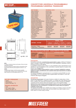
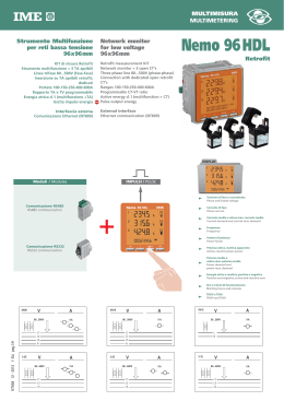
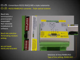
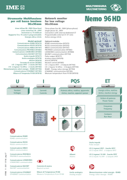
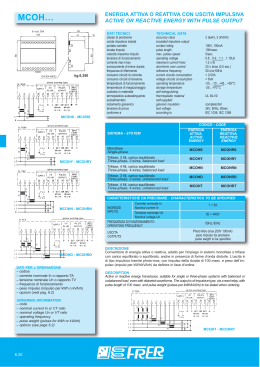
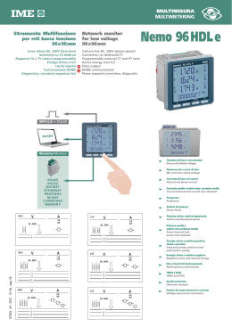
MULTIMISURA
MULTIMETERING
Strumento Multifunzione
per reti bassa tensione
96x96mm
Linea trifase 80...500V (fase-fase)
Inserzione su TA dedicati
Rapporto TA e TV esterni programmabile
Energia attiva cl.0,5
Uscita impulsi
Comunicazione RS485
Diagnostica, correzioni sequenza fasi
Nemo 96 HDL e
Network monitor
for low voltage
96x96mm
3-phase line 80...500V (phase-phase)
Connection on dedicated CT
Programmable external CT and VT ratio
Active energy class 0,5
Pulse output
RS485 communication
Phase sequence correction, diagnostic
IMPULSI • PULSE
DISPLAY
RS 48 5
Modulo/ Module
Tensione
T
ensione di fase e concatenata
concatenata
Phase
P
hase and linked
linked voltage
voltage
Tensione
T
ensione min. e max.
max. di fase
M
in.. and max. phase voltage
Min.
voltage
Corrente
Corrente di fase e di neutro
neutro
Neutral
Neutral and phase current
current
RS485
RS232
BACNET
ETHERNET
PROFIBUS
valore max. ccorrente
orrente media
Corrente
Corrente media e valore
Current demand and current
current max. demand
Current
Frequenza
Frequenza
Frequency
Frequency
Fattore di potenza
potenza
Fattore
Power factor
factor
Power
1N1E
V
50...290V
A
3-1E
/1A
/5A
80...500V
L
N
3N1E
V
80...500V
V
A
/1A
/5A
L1
L2
L3
A
3-2E
/1A
/5A
V
80...500V
P
Potenza
otenza a
attiva,
ttiva,, reattiva
reattiva apparente
apparente
eactive phase p
ower
Active,
power
Active, rreactive
Potenza media e
Potenza
valore max. potenza
potenza media
valore
Power demand and
Power
power max. demand
power
E
nergia attiva
attiva e rreattiva
eattiva p
ositiva,
Energia
positiva,
ttotale
otale e par
ziale
parziale
T
ositive active
active
otal and par
tial,, p
Total
partial,
positive
and rreactive
eactive energy
energy
A
/1A
/5A
Energia
E
nergia attiva
attiva e reattiva
reattiva negativa
negativa
Negative,
active
energy
tive and rreactive
eactive ener
gy
N
egative, ac
NT854 02 - 2015 6a Ed. pag.1/8
Ore
funzionamento
Or
e e minuti di funzionamen
to
Working
minutes
W
orking hours and minut
es
L1
L2
L3
N
3N3E
V
80...500V
L1
L2
L3
N
L1
L2
L3
THDV
THDV e THDI
THDV
THDV and THDI
Analisi
A
nalisi armonica
armonica
Harmonic
H
armonic analysis
analysis
A
/1A
/5A
3-3E
V
80...500V
L1
L2
L3
A
/1A
/5A
Fattore
cresta
Fattore di cr
esta ttensione
ensione e ccorrente
orrente
Voltage
factor
Voltage and current
current crest
crest fac
tor
MODELLO
LINEA
CONNESSIONE
CONNECTION
MODEL
Nemo 96HDL e
NETWORK
bt / LV
Monofase / Single-phase
4
Trifase, carico equilibrato
Three-phase, balanced load
4
Trifase, carico squilibrato
Three-phase, unbalanced load
4
INGRESSO
INPUT
DIAGNOSTICA, CORREZIONI SEQUENZA FASI / PHASE SEQUENCE CORRECTION, DIAGNOSTIC
VALORI NOMINALI
RATED VALUE
INGRESSO CORRENTE
INPUT CURRENT
80...500V
Corrente / Current
1 + 5A
TA dedicati / Dedicated CT
4
Isolato / Insulated
TV (kTV) / VT (kVT)
RAPPORTO PROGRAMMABILE
PROGRAMMABLE RATIO
4
Tensione / Voltage
TA /CT
1...10
Portate / Ranges
Ipn / Isn
max. kTV x kTA / max. kVT x kCT
1...9’999
99’990
Shunt
Precisione / Accuracy EN/IEC 61557-12
ENERGIA ATTIVA
ACTIVE ENERGY
Positiva, totale e parziale
Positive, total and partial
Negative, totale / Negative total
Precisione / Accuracy EN/IEC 61557-12
ENERGIA REATTIVA
REACTIVE ENERGY
VISUALIZZAZIONE
DISPLAY
TENSIONE
VOLTAGE
CORRENTE
CURRENT
Positiva, totale / Positive, total
Positiva, parziale / Positive, partial
POTENZA
POWER
DISTORSIONE ARMONICA Corrente / Tensione
HARMONIC DISTORTION Current / Voltage
4
cl.1
4
4
4
di Fase e concatenata / Phase and linked
4
di Fase e di neutro (calcolata)
Phase and neutral (computed)
4
di Neutro (misurata)
Neutral (measured)
Trifase / Three-phase
4
4
Di fase / Phase
4
Attiva, reattiva, apparente
Active, reactive, apparent
4
Media e media massima
Demand and max. demand
4
Attiva e reattiva di fase
Phase active and reactive
4
THD
Analisi / Analysis
FREQUENZA / FREQUENCY
MISURA C.C. 1 / D.C. 1 MEASURE
CONTAORE / RUN HOUR METER
SEQUENZA FASI ERRATA / WRONG PHASE SEQUENCE
TEMPERATURA / TEMPERATURE
IMPULSI / PULSES
USCITE
OUTPUT
4
Negativa, totale / Negative, total
Media-media massima di fase
Phase demand and max. demand
FATTORE DI POTENZA
POWER FACTOR
cl.0,5
Precisione energia cc
Energy accuracy dc
4
4
4
4
4
4
RELE’ ALLARMI / ALARM RELAYS
RELE’ ALLARMI + INGRESSI DIGITALI / ALARM RELAYS + DIGITAL INPUTS
ANALOGICA / ANALOGUE
COMUNICAZIONE
COMMUNICATION
RS485 MODBUS RTU
IF96002
4
RS485 + MEMORIA / RS485 + MEMORY
PROFIBUS
IF96007A
LONWORKS
M-BUS
BACNET
IF96014
ETHERNET
IF96015
TRASMISSIONE RADIO 868MHz / 868MHz RADIO TRASMISSION
1
Tensione, corrente, potenza, Ah positivi e negativi / 1 Voltage, current, power, Ah positive and negative
NT854 02 - 2015 6a Ed. pag.2/8
RS232
CODICI DI ORDINAZIONE
ORDERING CODE
MF96411
MF96421
MF96412
MF96422
LEGENDA:
USCITA
OUTPUT
Impulsi energia
Energy pulses
Impulsi energia + RS485
Energy pulses + RS485
Impulsi energia
Energy pulses
Impulsi energia + RS485
Energy pulses + RS485
AL. AUSILIARIA
AUX. SUPPLY
FIRMWARE
80...265Vca/ac
110...300V cc/dc
80...500V
1 e / and 5A
2.3
11...60V cc/dc
= Parametro Programmabile
= Parametro Azzerabile
VISUALIZZAZIONE
LEGEND:
= Programmable Parameter
= Reset Parameter
DISPLAY
Tipo display: cristallo liquido retroilluminato
Riduzione automatica della retroilluminazione, dopo 20s di inattività della tastiera
Contrasto: 4 valori selezionabili
Retroilluminazione selezionabile: 0 – 30 – 70 – 100%
Type of display : LCD backlit
Automatic backlit reduction off after 20s thet keyboard is not used
Contrast: 4 selectables values
Backlit: 0 – 30 – 70 – 100%
Punti di lettura: 10.000 4 cifre (altezza cifre 12mm)
N° of reading points: 10.000 4 digits (high digit 12mm)
Risoluzione: automatica, con il maggior numero di decimali possibili
Resolution: automatic, with the highest possible number of decimals
Conteggio energia: numeratore 8 cifre (altezza cifre 8mm)
Unità ingegneristica: visualizzazione automatica in funzione dei rapporti TA e TV
Punto decimale: automatico, con la maggiore risoluzione possibile
Aggiornamento lettura: 1,1s
Pagina personalizzata: grandezze visualizzabili all’accensione
PRECISIONE IN CONFORMITA’
Active energy
Corrente
Current
Tensione
Potenza attiva
Potenza reattiva
Potenza apparente
Frequenza
THD
PAGINE VISUALIZZAZIONE
U
TENSIONE
di fase e concatenata
VOLTAGE
phase and linked
TENSIONE MINIMA
di fase
MINIMUM VOLTAGE
phase
TENSIONE MASSIMA
di fase
MAXIMUM VOLTAGE
phase
DISTORSIONE ARMONICA TENSIONE
di fase o concatenata
VOLTAGE HARMONIC DISTORTION
phase or liked
ANALISI ARMONICA*
di fase o concatenata
H03...H09...H25
HARMONIC ANALYSIS*
phase or liked
FATTORE DI CRESTA
CREST FACTOR
Engineering units: automatic display according to the set VT and CT ratios
Decimal point: automatic, with the highest possible resolution
Reading update: 1,1s
Customized page: content of default page
Ea
cl.0,5
I
cl.0,5
Erv
Reactive energy
cl.1
U
Voltage
cl.0,5
P
Active power
cl.0,5
Qv
Reactive power
cl.1
Sv
Apparent power
Frequence
THD
La visualizzazione è suddivisa in quattro menù, accessibii con i relativi tasti
funzione:
Energy count: 8 digit counter (high digit 8mm)
CONFORMITY ACCURACY WITH EN/IEC 61557-12
Energia attiva
Energia reattiva
NT854 02 - 2015 6a Ed. pag.3/8
INGRESSO
INPUT
I
DISPLAY PAGES
cl.1
f
± 0,1Hz
THDu / THDi
cl.1
Display is divided into four menus which can be reached with the relevant function
keys:
PQS
ET
CORRENTE
di fase e di neutro
CURRENT
phase and neutral
POTENZA TRIFASE
attiva,reattiva, apparente, distorcente1
THREE-PHASE POWER
active, reactive, apparent, distorting1
FATTORE DI POTENZA
di fase e trifase
POWER FACTOR
phase and three-phase
PICCO CORRENTE MEDIA
di fase
MAX. CURRENT DEMAND
phase
POTENZA MEDIA
attiva, reattiva, apparente
POWER DEMAND
active, reactive, apparent
CONTAORE
RUN HOUR
CORRENTE MEDIA
di fase
CURRENT DEMAND
phase
MEDIA DELLE 3 CORRENTI
AVERAGE CURRENT
I1 + I2 + I3
3
DISTORSIONE ARMONICA CORRENTE
di fase
CURRENT HARMONIC DISTORTION
phase
ANALISI ARMONICA*
di fase
H03...H09...H25
HARMONIC ANALYSIS*
phase
FATTORE DI CRESTA
CREST FACTOR
POTENZA FASE
attiva, reattiva, apparente
PHASE POWER
active, reactive, apparent
PICCO POTENZA MEDIA
attiva, reattiva, apparente
MAX. POWER DEMAND
active, reactive, apparent
FREQUENZA
FREQUENCY
ENERGIA ATTIVA TOTALE
positiva e negativa
TOTAL ACTIVE ENERGY
positive and negative
ENERGIA REATTIVA TOTALE
positiva e negativa
TOTAL REACTIVE ENERGY
positive and negative
ENERGIA ATTIVA PARZIALE
positiva
PARTIAL ACTIVE ENERGY
positive
ENERGIA REATTIVA PARZIALE
positiva
PARTIAL REACTIVE ENERGY
positive
Nei sistemi trifase, normalmente la relazione fra P,Q ed S è la seguente:
S = V x I = √ P2 + Q2
Questo vale in assenza di distorsione armonica.
The total active or reactive energy (alternatively) is always displayed on all the
display pages.
In normal 3-phase systems, usually the relationship between P,Q and S is as in the
following:
S = V x I = √ P2 + Q2
Ove sia presente distorsione di corrente, la relazione deve essere corretta nel modo
This is true whwn no distortionis present in the currents. When the currents have
dove D assume il significato di potenza “distorcente”.
and D has the meaning “deforming” power.
*Il calcolo del contenuto spettrale del segnale tiene conto anche della possibile
*The calculation of the harmonic contents of the incoming signal keeps in account
In questi casi non vi sono armoniche alle frequenze multiple della fondamentale ma
In these cases, there aren’t any harmonics at frequencies multiple of the
seguente:
S = V x I = √ P2 + Q2 + D2
ANALISI ARMONICA
Modalità visualizzazione: fino alla 9a armonica o fino alla 25a armonica
distribuzione di inter-armoniche che tipicamente si ritrova nelle forme d’onda
ciclicamente interrotte.
all’interno degli intervalli fra una armonica e la successiva:
es.: 50Hz (fondamentale)
inter-armoniche: 87,5Hz (50-100Hz) o 112,5Hz (100-150Hz)
Al fine di poter presentare i dati in modo standard, il contenuto spettrale
nell’esempio viene attribuito, alla frequenza intermedia più vicina ovvero 100Hz
some way a harmonic contents, yhe formula must be corrected in this way:
S = V x I = √ P2 + Q2 + D2
HARMONIC ANALYSIS
Display mode: up to the 9th harmonic or up to the 25th harmonic
the possible presence of inter-harmonics that normally is found when the waveform
is cyclically interrupted (burst fired).
fundamental but in the middle of the ranges between two consecutive values:
eg.: 50Hz (fundamental)
inter-harmonics: 87,5Hz (50-100Hz) or 112,5Hz (100-150Hz)
To show the results in a standard way, the harmonic contents, as in the example, is
correctly attributed to the nearest central harmonic in the range 50...150Hz that is
(seconda armonica).
100Hz (second harmonic).
PARAMETRI PROGRAMMABILI
PROGRAMMABLE PARAMETERS
Programmazione: tramite tastiera frontale, 4 tasti
Programming: through front keyboard, 4 keys
LIVELLO 1
LEVEL 1
Accesso programmazione: protetto da password
Menù programmazione: suddiviso su due livelli
Pagina visualizzazione personalizzata
Connessione
Programming access: password-protected
Programming menu: subdivided on two levels
Display contrast
Contrasto display
Display backlit
Retroilluminazione display
Current rating
Corrente nominale
Start time (run hour meter)
Avvio conteggio contaore
RS485 communication
Comunicazione RS485
LIVELLO 2
Analisi Armonica
Rapporto trasformazione TA e TV esterni
Connection
Average power/current delay time
Tempo integrazione corrente / potenza media
Uscita impulsi
Customized display page
LEVEL 2
Pulse output
Harmonic Analysis
External CT and VT ratio
INGRESSO
INPUT
Inserzione su trasformatori di corrente esterni dedicati
Connection with external dedicated current transformers
Tensione monofase nominale Un: 230V
Single-phase voltage rating Un: 230V
Connessione: rete monofase – trifase 3 e 4 fili
Tensione trifase nominale Un: 400V
Tensione trifase: 80...500V (fase-fase)
Tensione monofase: 50...290V
Rapporto TV esterno: 1...10 (max. tensione primaria TV 1200V)
Corrente nominale In: 5A – 1A
Corrente massima Imax: 1,2In
Sovraccarico istantaneo: 20In/0,5s
Rapporto TA esterno: 1...9999 (max. corrente primaria TA 50kA/5A – 10kA/1A)
Frequenza nominale fn: 50Hz – 400Hz (selezione automatica)
Variazione ammessa: 45...65Hz (fn 50Hz) – 360...440Hz (fn 400Hz)
Tipo di misura: vero valore efficace
Contenuto armonico: fino a 50a armonica
Fattore di cresta: 2 (solo corrente)
Tempo di avviamento (conteggio energia): < 5s
Autoconsumo tensione: ≤ 0,2VA (fase-neutro alla tensione nominale)
Autoconsumo corrente: ≤ 1VA (per fase alla corrente massima 6A)
CORRENTE MEDIA – POTENZA MEDIA
Tempo integrazione: 5/8/10/15/20/30/60 min.
Connection: single –phase and three-phase network, 3 and 4-wire
Three-phase voltage rating Un: 400V
Three-phase voltage: 80...500V (phase-phase)
Three-phase voltage: 50...290V
External VT ratio: 1...10 (max. VT primary 1200V)
Current rating In: 5A – 1A
Max. current Imax: 1,2In
Instantaneous overload: 20In/0,5s
External CT ratio: 1...9999 (max. CT primary 50kA/5A – 10kA/1A)
Frequency rating fn: 50Hz – 400Hz (automatic selection)
Tolerance: 45...65Hz (fn 50Hz) – 360...440Hz (fn 400Hz)
Type of measurement: true RMS value
Harmonic content: up to 50h harmonic
Peak factor: 2 (current only)
Start time (energy count): < 5s
Voltage rated burden: 0,1VA (neutral-phase to voltage rating)
Current rated burden: 1VA (each phase to max. current 6A)
CURRENT DEMAND – POWER DEMAND
Average period: 5/8/10/15/20/30/60 min.
NT854 02 - 2015 6a Ed. pag.4/8
In tutte le pagine di visualizzazione è sempre presente l’energia totale attiva o
reattiva (alternate).
CONTAORE
Conteggio ore e minuti
Hours and minutes count
Potenza: potenza attiva trifase > 1W
Power: 3-phase active power > 1W
Avvio conteggio: selezionabile, presenza tensione opp. potenza
Tensione: tensione di fase > 20V
DIAGNOSTICA, CORREZIONE SEQUENZA FASI
Count start: power or voltage present selectable
Voltage: phase-voltage > 20V
PHASE SEQUENCE CORRECTION, DIAGNOSTIC
Nel software del dispositivo è presente un algoritmo di diagnostica e di ripara-zione
In the software of the device IME have added a specific functionality to detect and
sequenza di cablaggio a patto che le seguenti condizioni siano rispettate:
the connection sequence provided that the following conditions are respected:
della sequenza di inserzione voltmetrica ed amperometrica. La funzione è attivabile
a richiesta con password e consente di visualizzare e modificare via software la
1) Il conduttore di neutro (nella rete a 4 fili) sia correttamente posizionato al
morsetto corrispondente (normalmente numero 11).
2) Non siano presenti incroci di conduttori fra TA differenti (es. sulla fase 1 del
dispositivo vi sia un cavo proveniente dal TA 1 e sull’altro un cavo dal TA 2).
3) Il fattore di potenza sia compreso fra 1 e 0,5 Induttivo per ciascuna fase.
Vedi www.imeitaly.com “SUPPORTO TECNICO”.
USCITE
IMPULSI ENERGIA
Uscita impulsi compatibile con SO EN / IEC 62053-31
Optorelè con contatto SPST-NO libero da potenziale
Portata contatti: 27Vcc/ca – 50mA
Energia associabile: energia attiva o reattiva
NT854 02 - 2015 6a Ed. pag.5/8
RUN HOUR METER
correct many problems concerning voltage and / or current connection.
This function can be activated through password and allows to display and modify
1) The neutral wire (in a 4-wire network) is connected to the right terminal
(normally number 11).
2) No crossings between cables connected to CTs (e.g. avoid that on phase 1 of the
meter -terminals 1 and 3 - are connected some way both to CT1 and CT2).
3) The power factor is between 1 and 0,5 - Inductive load - for each phase.
See www.imeitaly.com “TECHNICAL SUPPORT”.
OUTPUTS
ENERGY PULSES
Pulse output according to SO EN / IEC 62053-31
Optorelay with potential-free SPST-NO contact
Contact range: 27Vdc/ac - 50 mA
Assignable energy: active or reactive energy
Peso impulsi: 10Wh(varh) - 100Wh(varh) - 1 kWh(kvarh) - 10kWh(kvarh) 100kWh(kvarh) - 1 MWh(Mvarh) - 10MWh(Mvarh)
Durata impulso: 50 – 100 – 200 – 300 - 400 - 500ms
COMUNICAZIONE RS485
Isolata galvanicamente da ingresso e ausiliaria
Standard: RS485 – 3 fili
Trasmissione: asincrona seriale
Protocollo: Modbus RTU - Modbus TCP (autoriconoscimento)
N° indirizzo: 1...255
Numero bit: 8
Bit di stop: 8
Bit di parità: nessuna – pari – dispari
Tempo di risposta a interrogazione: ≤ 100ms
Time out: 3...100ms
Velocità trasmissione: 4'800 – 9'600 – 19'200 - 38'400 bit/s
Formato word messaggio Modbus: Big Endian, Little Endian, Swap
Esempio
Messaggio richiesta: FF 03 03 01 00 02 80 51
Risposta
Big Endian
= FF 03 04 01 02 03 04 XX YY
Little Endian
= FF 03 04 04 03 02 01 XX YY
Swap
= FF 03 04 03 04 01 02 XX YY
N° massimo di apparecchi in rete: 32 (fino a 255 con ripetitore RS485)
Distanza massima dal supervisore: 1200m
MODULI OPZIONALI
Nei modelli MF96411, MF96412 (dotati di uscita impulsi) è possibile
aggiungere un modulo opzionale per ottenere un’uscita comunicazione RS485
o ETHERNET o BACNET o PROFIBUS.
Nei modelli MF96421, MF96422 (dotati di uscita impulsi e comunicazione RS485)
è possibile aggiungere un modulo opzionale per ottenere una ulteriore uscita
comunicazione, es. 2 uscite RS485, RS485+ETHERNET, RS485+BACNET,
RS485+PROFIBUS.
Pulse weight: 10Wh(varh) - 100Wh(varh) - 1kWh(kvarh) - 100kWh(kvarh) 1MWh(Mvarh) - 10MWh(Mvarh)
Pulse length: 50 - 100 - 200 - 300 - 400 - 500ms
RS485 COMMUNICATION
Galvanically insulated from input and auxiliary supply
Standard: RS485 - 3 wires
Transmission: asynchronous serial
Protocol: Modbus RTU - Modbus TCP (autorecognition)
Number of address: 1...255
Number of bits: 8
Stop bit: 8
Parity bit: none - even - odd
Query response time: ≤ 100ms
Time out: 3...100ms
Transmission speed: 4'800 - 9'600 - 19'200 - 38'400 bits/second
Modbus word message format: Big Endian, Little Endian, Swap
Example
Request message: FF 03 03 01 00 02 80 51
Response
Big Endian
= FF 03 04 01 02 03 04 XX YY
Little Endian
= FF 03 04 04 03 02 01 XX YY
Swap
= FF 03 04 03 04 01 02 XX YY
Max. number of devices that can be network-connected: 32 (up to 255 with
RS485 repeator)
Max. distance from the supervisor: 1200m
OPTIONAL MODULES
In the models MF96411, MF96412 (which have a pulse output) it is possible to
add an optional module in order to obtain a communication output RS485 or
ETHERNET or BACNET or PROFIBUS. In the models MF96421, MF96422
(which have a pulse output and RS485 communication) it is possible to add
an optional module in order to obtain another communication output, for
instance 2 RS485 outputs, RS485+ETHERNET, RS485+BACNET,
RS485+PROFIBUS.
ALIMENTAZIONE AUSILIARIA
AUXILIARY SUPPLY
Valore nominale Uaux ca: 80...265V
Frequenza nominale fn: 50 opp. 400Hz (selezione automatica)
Frequenza di funzionamento: 45…65Hz (fn 50Hz) opp. 360...440Hz (fn 400Hz)
Autoconsumo: ≤ 2,5VA (230Vca backlight 30% senza moduli esterni)
Rated value Uaux ac: 80...265V
Rated frequency fn: 50 or 400Hz (automatic selection)
Working frequency: 45…65Hz (fn 50Hz) or 360...440Hz (fn 400Hz)
Rated burden: ≤ 2,5VA (230Vac backlight 30% without external modules)
Rated value Uaux dc: 110...300Vdc
Rated burden: ≤ 3,5W (without modules, 110Vdc)
Valore nominale Uaux cc: 110...300Vcc
Autoconsumo: ≤ 3,5W (senza moduli, 110Vcc)
Protezione contro l’inversione di polarità
ISOLAMENTO
Protected against incorrect polarity
(EN/IEC 61010-1)
Categoria di installazione: III
Grado di inquinamento: 2
Tensione di riferimento per l’isolamento: 300V (Fase - neutro)
Circuiti considerati Considered circuits
Alimentazione / Ingressi voltmetrici Supply / Voltmetric inputs
Ingressi misura / Comunicazione RS485
INSULATION
Installation category: III
Pollution degree: 2
Insulation voltage rating: 300V (phase - neutral)
PROVE TESTS
Tensione a impulso 1,2 / 50μs 0,5J
Voltage test 1,2 / 50μs 0,5J
Tensione alternata valore efficace 50Hz 1min
Alternating voltage r.m.s value 50Hz 1min
6kV
3kV
6kV
3kV
6kV
3kV
Measure inputs / RS485Communication
Ingressi misura / Uscita impulsi Meaure inputs / Pulse output
Tutti i circuiti e massa All circuits and earth
COMPATIBILITA’ ELETTROMAGNETICA
(EN/IEC 61010-1)
4kV
ELETROMAMAGNETIC COMPATIBILITY
Emissione in accordo con EN / IEC 61326-1 classe B
Emission according to EN 61326-1 class B
CONDIZIONI AMBIENTALI
ENVIRONMENTAL CONDITIONS
Immunità in accordo con EN / IEC 61326-1
Temperatura di riferimento: 23°C ± 2°C
Campo di funzionamento specificato: -5...55°C
Campo limite per l’immagazzinamento e trasporto: - 25...70°C
Adatto all’utilizzo in climi tropicali
Massima potenza dissipata 1: ≤ 5W
Per il dimensionamento termico dei quadri
Reference temperature: 23°C ± 2°C
Specified operating range: -5...55°C
Limit range for storage and transport: - 25...70°C
Suitable for tropical climates
Max. power dissipation 1: ≤ 5W
1
CUSTODIA
For switchboard thermal calculation
HOUSING
Custodia: incasso (foratura pannello 92x92mm)
Housing: flush mounting (panel cutout 92x92mm)
Profondità massima: 81mm (con moduli opzionali)
Max. depth: 81mm (with optional modules)
Frontale: 96x96mm
Profondità: 62mm
Connessioni: morsetti fissaggio a vite (ingressi di corrente)
a estrazione (ingressi di tensione)
Front frame: 96x96mm
Depth: 62mm
Connections: screw terminals (input current)
to plug out (input voltage)
Materiale custodia: policarbonato autoestinguente
Housing material: self-extinguishing policarbonate
PORTATA MORSETTI
TERMINAL CAPACITY
Grado di protezione (EN60529): IP54 frontale, IP20 morsetti
Peso: 285 grammi
INGRESSO TENSIONE
Cavo rigido: min.0,05mm2 / max. 4,5mm2
Cavo flessibile: min.0,05mm / max. 2,5mm
2
Coppia serraggio consigliata: 0,6Nm
2
INGRESSO CORRENTE
Weight: 285 grams
VOLTAGE INPUT
Rigid cable: min.0,05mm2 / max. 4,5mm2
Flexible cable: min.0,05mm2 / max. 2,5mm2
Tightening torque advised: 0,6Nm
CURRENT INPUT
Rigid cable: min.0,05mm2 / max. 6mm2
Cavo rigido: min.0,05mm2 / max. 6mm2
Flexible cable: min.0,05mm2 / max. 4mm2
Cavo flessibile: min.0,05mm2 / max. 4mm2
Tightening torque advised: 1Nm
Coppia serraggio consigliata: 1Nm
ALIMENTAZIONE AUSILIARIA
Cavo rigido: min.0,05mm2 / max. 4,5mm2
Protection degree (EN60529): IP54 front frame, IP20 terminals
AUX. SUPPLY
Rigid cable: min.0,05mm2 / max. 4,5mm2
Cavo flessibile: min.0,05mm / max. 2,5mm
Flexible cable: min.0,05mm2 / max. 2,5mm2
Cavo rigido: min.0,05mm2 / max. 4,5mm2
Rigid cable: min.0,05mm2 / max. 4,5mm2
2
Coppia serraggio consigliata: 0,6Nm
USCITE
2
Cavo flessibile: min.0,05mm2 / max. 2,5mm2
Coppia serraggio consigliata: 0,6Nm
Tightening torque advised: 0,6Nm
OUTPUT
Flexible cable: min.0,05mm2 / max. 2,5mm2
Tightening torque advised: 0,6Nm
NT854 02 - 2015 6a Ed. pag.6/8
1
Immunity according to EN 61326-1
MODULI OPZIONALI
OPTIONAL MODULES
In the table are listed module composition constrictions:
Nella tabella vengono riportati i vincoli di composizione dei moduli: numero
max. number of modules and connection position.
massimo moduli e posizione di inserimento.
Codice Code
Descrizione Description
Comunicazione RS485
RS485 communication
Comunicazione RS232
RS232 communication
Comunicazione PROFIBUS
PROFIBUS communication
Comunicazione BACNET
BACNET communication
Comunicazione ETHERNET
ETHERNET communication
IF96001
IF96002
IF96007A
IF96014
IF96015
Posizione Position
N. Max.
A
B
C
D
Firmware1
Nota Tecnica
Technical Note
1
•
1.0
NT675
1
•
1.0
NT676
1
•
2.3
NT682
1
•
1.0
NT743
1
•
1.0
NT785
On the table it is shown the Firmware version of the meter which supports
In tabella viene indicata la versione Firmware dello strumento che supporta la
1
1
funzione del modulo aggiuntivo.
the function of the extra module.
By using the RS485 communication (where is present) or an
Utilizzando la comunicazione RS485 (dove presente) o un
IF96001 (RS485) or IF96002 (RS232) communication
modulo comunicazione IF96001 (RS485) o IF96002 (RS232) è
module it is possible to update the Firmware version directly
possibile aggiornare la versione Firmware direttamente in
on field, with the help of a PC and the download software.
campo, con l’ausilio di un PC e del software di download.
A
POSIZIONE TERMINALI
TERMINALS POSITION
1 3 4 6 7 9
T1
T2
2
DIMENSIONI
5
8
11
20 21
DIMENSIONS
NT854 02 - 2015 6a Ed. pag.7/9
81*
96
92
92
96
62
12
* Modulo opzionale
Option module
SCHEMI D’INSERZIONE
WIRING DIAGRAMS
F
: 1A gG
S 1000/394
RS 485
AUX.
Rx / Tx GND SUPPLY
+ –
+ –
INPUT
CURRENT
VOLTAGE
1n1E
2 5 8 11 1 3 4 6 7 9
Linea Monofase
Single phase network
TI T2
3
5
4
20 21
11
2
a
b
A
B
F
S1
L
P1
N
LOAD
X
S 1000/395
RS 485
INPUT
CURRENT
VOLTAGE
3-1E
2 5 8 11 1 3
5
2
Linea Trifase 3 Fili 1 SIstema
Three-phase 3-wires network 1 Systems
Rx / Tx GND
7 9
4 6
+
3
TI T2
–
4
5
AUX.
SUPPLY
+ –
20 21
8
a
b
a
b
A
B
A
B
F
S1
L1
P1
X
L2
LOAD
X
X
L3
S 1000/396
RS 485
INPUT
CURRENT
VOLTAGE
2 5 8 11 1 3
3N1E
Rx / Tx GND
7 9
4 6
+
3
TI T2
–
4
5
AUX.
SUPPLY
+ –
20 21
2 5 8 11
Linea Trifase 4 Fili, 1 Sistema
Three-phase 3-wires network, 1 Systems
F
a
A
S1
L1
P1
X
L2
X
LOAD
X
L3
X X X
N
S 1000/397
INPUT
2 5 8 11 1 3
3-2E
5
2
Linea Trifase 3 fili, 2 Sistemi
Three-phase 3-wires network, 2 Systems
RS 485
CURRENT
VOLTAGE
Rx / Tx GND
7 9
4 6
+
3
TI T2
–
4
5
AUX.
SUPPLY
+ –
20 21
8
a
b
a
b
A
B
A
B
L1
F
S1
P1
X
LOAD
X
L2
X
S1
L3
P1
RS 485
AUX.
Rx / Tx GND SUPPLY
+
–
+ –
INPUT
CURRENT
VOLTAGE
2 5 8 11 1 3
3-3E
5
2
Linea trifase 3 fili 3 Sistemi
Three-phase 3-wires network, 3 Systems
L1
L2
L3
4 6
7 9
TI T2
3
4
8
a
b
a
b
A
B
A
B
5
20 21
F
S1
P1
X
S1
P1
X
S1
P1
X
LOAD
NT854 02 - 2015 6aEd. pag.8/9
S 1000/398
S 1000/399
NT854 02 - 2015 6a Ed. pag.9/9
La I.M.E. S.p.A. si riserva in qualsiasi momento, di modificare le caratteristiche tecniche senza darne preavviso. / I.M.E. S.p.A. reserves the right, to modify the technical characteristics without notice.
INPUT
2 5 8 11 1 3
3N3E
RS 485
CURRENT
VOLTAGE
4 6
Rx / Tx GND
7 9
+
3
TI T2
–
4
5
AUX.
SUPPLY
+ –
20 21
2 5 8 11
Linea Trifase 4 fili, 3 Sistemi
Three-phase 4-wire network, 3 Systems
F
a
A
S1
L1
P1
X
S1
L2
X
P1
X
S1
L3
P1
LOAD
X X X
N
S 1000/400
INPUT
RS 485
CURRENT
VOLTAGE
2 5 8 11 1 3
3-3E
5
2
7 9
4 6
+
3
TI T2
–
4
5
AUX.
SUPPLY
+ –
20 21
8
a
b
a
b
A
B
A
B
Linea trifase 3 fili 3 Sistemi
Three-phase 3-wires network, 3 Systems
Rx / Tx GND
F
S1
L1
P1
L2
S1
P1
L3
X
X
S1
LOAD
X
P1
S 1000/401
RS 485
INPUT
CURRENT
VOLTAGE
2 5 8 11 1 3
3N3E
7 9
+
3
TI T2
–
4
2 5 8 11
A
L1
L2
L3
N
5
AUX.
SUPPLY
+ –
20 21
F
a
Linea Trifase 4 fili, 3 Sistemi
Three-phase 4-wire network, 3 Systems
www.imeitaly.com
4 6
Rx / Tx GND
S1
P1
X
S1
P1
X
X
S1
P1
X X X
LOAD
Scaricare