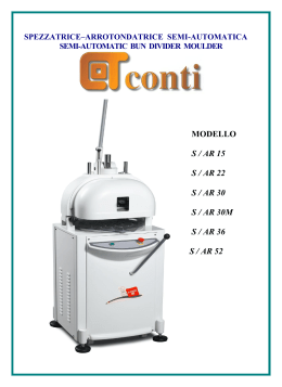
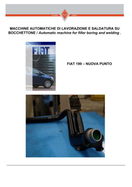
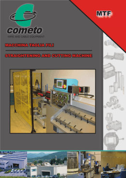
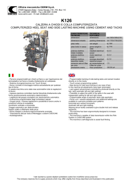
Via Carnia, 15 z.i.p.r.
33078 S.Vito al Tagliamento (PN)
tel. +39 0434 857000
fax +39 0434 857001
PORZIONATRICE
PIZZA DIVISEUSE
PO 300
ISTRUZIONI PER L’USO E LA
MANUTENZIONE
INSTRUCTIONS DE SERVICE
1/64
DECLARATION
DE
CONFORMITÈ
DECLARATION
OF CONFORMITY
In accordo con la Direttiva Bassa Tensione 73/23 CEE, con la Direttiva 89/336 CEE (Compatibilità Elettromagnetica),
con la direttiva 98/37 CEE (macchine), integrate dalla marcatura CE secondo la Direttiva 93/68 CEE.
En accord avec la Directive Basse Tension 73/23 CEE, avec la Directive 89/336 CEE (Compatibilité Electromagnétique), avec la Directive 98/37 CEE (machines) intégrés par le marquage CE selon la Directive 93/68 CEE
Tipo d’apparecchio – Type d’appareillage
:
Macchina: PORZIONATRICE
Machine: PIZZA DIVISEUSE
Marchio commerciale – Marque commerciale : PIZZA GROUP
Modello – Modèle
: PO 300
Costruttore – Constructeur
: PIZZA GROUP SRL
Indirizzo – Adresse
:
I – 33078 SAN VITO AL TAGLIAMENTO (PN)
Via Carnia 15 Z.I.P.R.
Telefono – Téléphone
: +39 0434 857000
Telefax – Téléfax
: +39 0434 857001
Le norme armonizzate o le specifiche tecniche (designazioni) che sono state applicate in accordo con le regole della
buon’arte in materia di sicurezza in vigore nella CEE sono:
Les normes harmonisées ou les spécifications techniques (désignations) qui ont été appliquées en accord avec les
règles de l’art en matière de sécurité en vigueur dans la CEE sont:
Norme o altri documenti normativi
Normes ou autres documents normatif
Rapporto di collaudo-Schede tecniche
Rapports d’essais – Fiche techniques
EN 60204-1 EN 60335-2-64
EN 292-1 EN 292-2 EN 294
EN 55014 EN 55104
EN 60555-2 EN 60555-3
Informazioni ulteriori
Ultérieures informations
In qualità di costruttore e/o rappresentante autorizzato della società all’interno della CEE, si dichiara sotto la propria
responsabilità che gli apparecchi sono conformi alle esigenze essenziali previste dalle Direttive su menzionate.
En qualité de constructeur et/ou représentant autorisé de la Société à l’intérieur de la CEE, nous déclarons sous notre
propre responsabilité que les appareils sont conformes aux exigences essentielles prévues par les Directives
mentionnées ci-dessus.
Bellotto Carlo
San Vito al Tagliamento PN
29.01.2003
Presidente – Président
2/64
1) MODELLI E DIMENSIONI
DIMENSIONI
(mm)
MOD.
PO300
PESO NETTO
(Kg)
LARG.
PROF.
ALT.
475
800
650
101
2) DATI TECNICI
CONNESSIONE ELETTRICA
MOD.
PO300
TENSIONE
POTENZA
CAVO
V – AC
Kw
(Tipo H07RNF)
380….400 V / 3 N ~
0,46
5 x 1,5 mm²
230 V / 3 ~
0,46
4 x 2,5 mm²
•
CAPACITÀ VASCA = KG 30 MASSIMO (PASTA NON LIEVITATA)
•
LA TARGHETTA DATI SI TROVA SUL FIANCO DESTRO DELL’APPARECCHIO
3/64
4/64
PO 300
fig. 1
AVVERTENZE GENERALI
Leggere attentamente le avvertenze contenute nel presente libretto in quanto forniscono
importanti indicazioni riguardanti la sicurezza di installazione, uso e manutenzione.
Conservare questo libretto per ogni ulteriore consultazione dei vari operatori. Dopo aver
tolto l’imballaggio assicurarsi dell’integrità dell’apparecchiatura. In caso di dubbio, non
utilizzare l’apparecchiatura e rivolgersi a personale professionalmente qualificato. Prima di
collegate l’apparecchiatura, accertarsi che i dati di targa siano corrispondenti a quelli della
rete di alimentazione elettrica: la targhetta dei dati tecnici è posta sul fianco destro e
riporta tutti i dati necessari all’installazione.
L’apparecchiatura deve essere utilizzata solo da personale addestrato all’uso della stessa.
Prima di effettuare operazioni di pulizia e manutenzione, disinserire l’apparecchiatura dalla
rete di alimentazione elettrica. Disattivare l’apparecchio in caso di guasto o di cattivo
funzionamento. Per l’eventuale riparazione rivolgersi solamente ad un centro d’assistenza
tecnica autorizzato e richiedere l’utilizzo di ricambi originali.
Il mancato rispetto di quanto sopra può compromettere la sicurezza dell’apparecchiatura.
Tutti i lavori di messa in opera e di installazione possono essere eseguiti esclusivamente
da personale specializzato ed in conformità alle prescrizioni vigenti. La sicurezza elettrica
di questa apparecchiatura è assicurata soltanto quando la stessa è correttamente
collegata ad un efficace impianto di messa a terra come previsto dalle vigenti norme di
sicurezza elettrica. È necessario verificare questo fondamentale requisito di sicurezza, in
caso di dubbio richiedere un controllo accurato dell’impianto da parte di personale
professionalmente qualificato.
Il costruttore non può essere considerato responsabile per eventuali danni causati dalla
mancanza di messa a terra dell’impianto.
L’emissione di rumori dell’apparecchio è inferiore a 85 dB (A).
ISTRUZIONI PER L’INSTALLATORE
L’apparecchio PO 300 può essere installato:
A) Sopra un supporto di sostegno già esistente presso l’utente; in questo caso il piano
di appoggio deve essere in grado di portare il peso della macchina. Inoltre tenere in
considerazione quanto dettato dalle normative ergonomiche.
B) Sopra supporti, di portata superiore a 150 Kg, che possono essere forniti a
richiesta.
La BM/2 è composta da due apparecchiature fornite in imballi separati e distinti da due
contrassegni:
PO 300 (PORZIONATRICE)
NT (NASTRO TRASPORTATORE)
L’apparecchio è stato progettato in modo che possa funzionare solo se:
1° ) La porzionatrice è collocata sopra il nastro (vedi fig. 1)
2° ) Il connettore femmina volante Xp, posto sotto la porzionatrice, è collegato al
connettore maschio fisso Xs, posto all’interno del nastro (vedi capitolo
“collegamento elettrico”).
5/64
Lavatoio
Impastatrice
PO 300
• SCHEMA DISPOSIZIONE MACCHINA
Carrello porta cassette
fig. 2
L’installatore dovrà tener conto di eventuali interventi di manutenzione nel fianco destro e
nella parte posteriore dell’apparecchio.
Inoltre dovrà considerare lo spazio utile, necessario all’utente per svolgere al meglio e, in
condizioni di sicurezza il proprio lavoro (vedi schema – fig. 2).
1)
POSA IN OPERA DEGLI APPARECCHI
Togliere il nastro dall’imballo e sistemarlo nel luogo di utilizzazione.
Togliere la porzionatrice dall’imballo e sistemarla sopra il nastro come indicato in fig. 1
facendo attenzione al connettore posto sotto la porzionatrice.
L’apparecchio deve essere messo in opera su un piano perfettamente orizzontale; se
esistono della aplanarità devono essere eliminate avvitando o svitando i piedini d’appoggio
regolabili. Se la macchina è asservita da una impastatrice, quest’ultima dovrebbe trovarsi
sul lato sinistro della PO 300 per facilitare l’operazione di carico della vasca della
porzionatrice (vedi schema disposizione macchina; disegno scala 1:40).
2)
COLLEGAMENTO ELETTRICO
ATTENZIONE: Prima di effettuare l’allacciamento alla linea elettrica bisogna collegare la
porzionatrice con il nastro.
-
Prendere il connettore Xp posto sotto la porzionatrice e collegarlo con il connettore
maschio Xs fissato sul nastro (vedi schema elettrico).
6/64
L’apparecchiatura viene consegnata predisposta per il funzionamento alla tensione
riportata nella targhetta caratteristiche.
L’apparecchiatura è dotata di un cavo flessibile per l’allacciamento alla linea elettrica
del tipo con isolamento in gomma H07RN-F e di sezione come da “dati tecnici
dell’apparecchio”.
L’equipaggiamento elettrico della macchina deve essere connesso a un conduttore
neutro (N) se alimentato a 380 – 400 V.
Assicurarsi che il voltaggio e la potenza di rete siano adeguati ad erogare i Kilowatts
richiesti come da “dati tecnici dell’apparecchio”. Il collegamento alla linea elettrica è
possibile solo se tra la rete di alimentazione e la macchina, esiste un interruttore
principale murario unipolare conforme alle norme vigenti, con un’apparecchiatura di
contatto minima di 3 mm per polo. Inoltre la tensione di alimentazione a macchina
funzionante, non deve discostarsi dal valore della tensione nominale di ± 10%.
L’interruttore principale deve essere situato i prossimità della macchina e deve essere
di facile accessibilità.
È indispensabile collegare l’apparecchiatura a terra e verificare l’efficacia
dell’allacciamento elettrico di protezione. L’apparecchiatura deve essere inoltre inclusa
in un sistema equipotenziale la cui efficacia deve essere opportunamente verificata
secondo quanto riportato nella normativa in vigore. Il collegamento viene effettuato
mediante due viti contrassegnate dal simbolo 9, poste una sul fianco destro nelle
vicinanze dell’ingresso del cavo elettrico, e l’altra nella parte posteriore del nastro.
-
All’accensione della macchina accertarsi che il senso di rotazione della spirale e del
coltello avvenga come indicato dalle frecce poste sulla porzionatrice (senso antiorario),
mentre il senso di rotazione del nastro trasportatore deve coincidere con la freccia posta
sul nastro. In caso contrario disinserire immediatamente la macchina dalla rete di
alimentazione elettrica e invertire due fasi direttamente sulla spina del cavo di
alimentazione.
IL COSTRUTTORE DECLINA OGNI RESPONSABLITÀ QUAL’ ORA QUESTA NORMA
ANTIINFORTUNISTICA NON VENGA RISPETTATA.
3)
-
SISTEMI DI SICUREZZA DELL’APPARECCHIATURA (vedi fig. 3)
PROTEZIONI PER L’OPERATORE
1) Il coperchio A (fig. 3) impedisce l’accesso alla vasca della porzionatrice durante la
lavorazione; infatti è dotato di un microinterruttore che permette il funzionamento
della PO 300 solo se il coperchio è completamente chiuso.
2) Il portello anteriore N (fig. 3) protegge l’operatore dal movimento pericoloso del
coltello taglia pasta e del nastro trasportatore. La PO 300 non parte se il portello
anteriore non è completamente abbassato.
-
PROTEZIONI PER L’APPARECCHIATURA
1) Per evitare danni alla porzionatrice, la macchina è dotata di un microinterruttore che
rivela la posizione del cassetto dosa-taglia (fig. 2); se quest’ultimo non è
perfettamente chiuso la PO 300 non funziona.
7/64
PROTEZIONE TERMICA
-
1) Ogni motore della PO 300 è protetto da u relè termico a riarmo manuale.
I relè termici che proteggono i motori sono dietro il fianco destro della porzionatrice
e del nastro.
4)
SOSTITUZIONI PARTI DI RICAMBIO
4.1
Prima di sostituire parti
l’apparecchiatura della rete.
della
macchina scollegare in modo onnipolare
-
MOTORE COLTELLO
Sollevare il portello anteriore N (fig. 3); alzare la leva dal carrello di regolazione E (vedi
fig. 4), togliere il coltello AH045 (tav. 3) svitando i pomoli AC056. togliendo la
protezione A2L04 (tav. 3), fissata con viti a vista, si accende al motore coltello.
-
MICROINTERRUTTORI
La tav. 2 mostra la posizione dei microinterruttori e il loro sistema di fissaggio.
-
MOTORE SPIRALE
Si trova dietro il fianco destro della porzionatrice (tav. 4).
-
COMPONENTI ELETTRICI PORZIONATRICE (tav. 2)
Tolto il fianco destro e il cruscotto comandi (viti a vista) si accede facilmente a tutti i
componenti.
-
COMPONENTI ELETTRICI NASTRO (tav. 5)
Tolto il fianco destro (viti a vista) si accede a tutti i componenti.
-
MOTORI NASTRO (tav. 5)
Separare la porzionatrice dal nastro e staccare il connettore volante Xp: così facendo
si accede facilmente al motore del nastro.
ISTRUZIONI PER L’UTENTE
Si raccomanda all’utente di verificare che l’installazione dell’apparecchio sia stata fatta i
modo idoneo; la ditta costruttrice non risponde delle garanzie o dei danni fatti derivanti da
cattiva installazione, imperfetta manutenzione, imperizia nell’uso.
Prima di mettere in funzione la PO 300, leggere attentamente le istruzioni per l’uso
contenute nel presente opuscolo, con particolare attenzione alle norme relative ai
dispositivi di sicurezza. Spegnere sempre l’interruttore elettrico principale alla fine
dell’utilizzazione dell’apparecchio, soprattutto durante le operazioni di manutenzione e
riparazione.
8/64
9/64
fig. 3
La macchina deve essere utilizzata conformemente alle regole e pulita accuratamente.
Tutti i dispositivi di sicurezza devono essere mantenuti efficienti. Variazioni ed applicazioni
sulla macchina di dispositivi non sono ammessi e comportano la cessazione di ogni
prestazione in garanzia.
5)
USO DELL’APPARECCHIO (Vedi fig. 3)
Prima di accendere la macchina introdurre l’impasto non lievitato nell’apposita vasca B
alzando il coperchio A quindi abbassarlo per assicurarsi l’intervento del microinterruttore di
sicurezza. Premere l’interruttore generale Q1 ed il pulsante di marcia SB4 della
porzionatrice. Verificare che il peso delle prime porzioni di pasta corrisponda alla
grammatura voluta. La grammatura si aumenta ruotando in senso orario la manopola I e si
diminuisce ruotando la stessa in senso antiorario (vedi fig. 4). Provvedere ad alimentare la
vasca della porzionatrice con successivi impasti non lievitati e raccogliere le porzioni in
uscita dal nastro P. a fine lavoro arrestare la macchina premendo il pulsante di arresto
SB3.
6)
DOTAZIONE DELLA MACCHINA
La PO 300 ha in dotazione n° 3 imbuti.
La tabella sotto illustrata mostra tutti i tipi di imbuti con relativo campo di lavoro:
dotazione di serie, se non specificato prima dell’ordine.
PO300
10/64
L’utente dovrà dotare la macchina dell’imbuto adatto al peso della porzione di pasta da
lavorare. Per esempio:
PIZZE Ø 300 mm PESO DELLA PORZIONE = 200 gr
CONO DA APPLICARE ALLA PORZIONATRICE AH025
fig. 4
-
SOSTITUZIONE DELL’IMBUTO
Staccare in modo onnipolare la macchina della rete elettrica. Sollevare il portello anteriore
N, sollevare la leva carrello di regolazione E e aprire il cassonetto dosa – taglia L (fig. 3 e
fig. 4). Allentare i due pomelli F e ruotare l’imbuto di quanto basta per l’estrazione.
Reinserire l’imbuto prescelto nell’apposita sede, rimuovendo eventuali residui di pasta, ed
avvitare contemporaneamente i due pomelli F (fig. 4). Assicurato l’imbuto alla macchina,
chiudere il cassonetto dosa – taglia L e riportare la leva del carrello E in posizione di
lavoro. L’intervento del micro di sicurezza avviene solo con la perfetta chiusura del
cassonetto dosa – taglia L: solo così la macchina può funzionare.
11/64
Schema elettrico 380…400 V / 3N~
12/64
Schema elettrico 230 V / 3~
13/64
LEGENDA SCHEMA ELETTRICO
X1 = MORSETTIERA CAVO ALIMENTAZIONE
X3 = MORSETTIERA COLLEGAMENTO INTERRUTTORI DI POSIZIONE
XP = CONNETTORE FEMMINA
Q1 = INTERRUTTORE GENERALE
HL1 = LAMPADA ALIMENTAZIONE
SQ1 = INTERRUTTORE DI POSIZIONE PORTELLO ANTERIORE
SQ2 = INTERRUTTORE DI POSIZIONE COPERCHIO VASCA
SQ3 = INTERRUTTORE DI POSIZIONE CASSETTO DOSA TAGLIA
SQ5 = MICROINTERRUTTORE DOSA PASTA
SQ6 = MICROINTERRUTTORE COLTELLO
SB3 = PULSANTE D’ARRESTO
SB4 = PULSANTE DI MARCIA
KM1-2 = TELERUTTORE
FR1-2 = RELÈ TERMICO
KA1 = RELÈ
M1 = MOTORIDUTTORE SPIRALE 0,37 KW 230 / 400 V
M2 = MOTORIDUTTORE COLTELLO 0,09 KW 230 / 400 V
KT1 = TEMPORIZZATORE COLTELLO (0,2 sec.)
14/64
7)
PULIZIA E MANUTENZIONE
Prima di iniziare le operazioni di pulizia e/o manutenzione scollegare in modo onnipolare la
macchina dalla rete elettrica. Pulire giornalmente la macchina con acqua tiepida saponata,
quindi risciacquare abbondantemente e asciugare con cura. Evitare nel modo più assoluto
di pulire con pagliette, spazzole o raschietti di acciaio comune in quanto possono
depositare particelle ferrose che ossidandosi provocano punti di ruggine. Evitare di
ricorrere all’uso di lame od utensili che provochino danni o rugosità superficiali.
ATTENZIONE: non lavare l’apparecchiatura con getti d’acqua diretti e in pressioni poiché
eventuali infiltrazioni ai componenti elettrici potrebbero pregiudicare il regolare
funzionamento dell’apparecchiatura e dei sistemi di sicurezza.
Per una accurata pulizia della PO 300 è necessario eseguire le seguenti operazioni (vedi
fig. 3, fig. 4):
Sollevare il portello anteriore N e alzare la leva di regolazione E.
Svitare i due pomoli P e togliere il coltello M: lavare sotto un getto d’acqua calda.
Aprire il cassonetto dosa – taglia L.
Allentare i due pomelli F e ruotare l’imbuto quanto basta per l’estrazione: lavare sotto
un getto d’acqua calda.
5° Svitare la ghiera esterna D (fig. 3), che si trova nella parte posteriore della
porzionatrice, ed estrarre frontalmente la spirale C; lavare abbondantemente sotto un
getto d’acqua calda.
6° Pulire la vasca con una spugna ben strizzata d’acqua calda eliminando i residui di
pasta che seccando possano alterare la posizione dell’imbuto o della spirale.
Fare attenzione che nella sequenza inversa di rimontaggio avvenga il calettamento
della spirale C sui due pioli di trascinamento della testata della macchina.
Dopo aver correttamente rimontato la spirale C, l’imbuto G e il coltello M procedere
alla pulizia interna del nastro.
7° Svitare e sfilare la manopola nera T (vedi tav. 3, particolare AC054 tav. 5) che si trova
sul lato destro del nastro trasportatore. Sfilare il nastro sempre dal lato destro e
procedere ad una accurata pulizia.
Fare attenzione che nella sequenza inversa di rimontaggio, il perno rullo motore
KF026 (tav. 5) si agganci al blocco snodo nastro KF027 (tav. 5).
1°
2°
3°
4°
Si raccomanda cautela nell’eseguire
deterioramento delle parti interessate.
suddette
operazioni,
onde
evitare
il
Non sono necessari particolari lavori di manutenzione, ma si raccomanda di far
controllare l’apparecchio da specialisti ogni 4 anni.
Una buona manutenzione garantisce un perfetto funzionamento ed una lunga durata
dell’apparecchio.
15/64
1) TYPE AND DIMENSIONS
OVERALL DIMENSION
(mm)
MOD.
PO 300
WIDTH
DEPTH
HEIGHT
475
800
650
NET WEIGHT
(Kg)
101
2) DATI TECNICI
ELECTRIC CONNEXION
MOD.
PO 300
RATING VOLTAGE
RATING VOLTAGE
CABLE
V – AC
Kw
(Type H07RNF)
380…400 V / 3 N ~
0,46
5 x 1,5 mm²
230 V / 3 ~
0,46
4 x 2,5 mm²
•
CAPACITY OF THE UPPER TANK = MAX 30 KG (NOT LEAVENED DOUGH)
•
THE LABEL WITH TECHNICAL DATA IS ON THE RIGHT SIDE OF THE MACHINE
16/64
17/64
PO 300
Picture 1
GENERAL WARNINGS
Carefully read the warnings contained in this manual for important information regarding
the safety of installation, use and maintenance of the equipment. Keep this manual at
disposal of the different operators.
After having removed the packing from the equipment, make sure that it is in good
conditions. In case of doubt, do not use the equipment and contact a qualified engineer.
Before connecting the equipment, make sure that the operating data are corresponding to
the data of the electric supply mains: data plate is located on the back wall data required
for the installation.
The equipment has to be used just by trained personnel. Before cleaning and servicing,
disconnect the equipment from the electric supply mains.
Stop the equipment in case of faulty operation. For any repair, get in touch with a qualified
service centre and ask for original spare parts.
The non-fulfilment of the requirements contained in this manual may effect the safety of
the equipment. The machine should be installed and operated just by trained personnel
and in compliance with the regulations in force. We will answer for the electric safety of
this equipment only if it is correctly connected to a suitable earthing system as provided by
the electric safety standard in force. It is very important to verify this safety requirement. In
case of doubt ask trained personnel to carefully check the plant.
The manufacturer will not held responsible for any damage caused by the lack of the
earthing system in the plant.
The noise level of the installation is under 85 dB (A).
INSTRUCTIONS FOR THE INSTALLER
The unit PO 300 can be installed:
A) On an already existing support at the user’s premises; in the case the supporting
plane must be able to support the machine. Also consider the details of the
ergonomic normative law.
B) On supports, with more than 150 Kg of capacity, that may be supplied on request.
The PO 300 machine is composed by two units in different package and marked with two
label:
PO 300 (PORZIONATRICE)
NT (NASTRO TRASPORTATORE)
The unit has been designed in order that it can run only when:
1° )
The dough divider machine is set on the conveyor belt (see Picture 1)
2° )
The female connector Xp, set under the dough portioning machine, is connected with
the fix tap connector Xs, which is set inside the conveyor belt (see chapter “electric
connection”).
18/64
•
SCHEME FOR ARRANGEMENT OF THE MACHINE
Picture 2
The installer will have to consider any possible maintenance works in the right side and on
the back of the unit. Moreover, he must take into consideration the place in order to work
easily and in safety conditions during maintenance works (see scheme – Picture 2).
1 ) INSTALLATION OF THE EQUIPMENT
Remove the conveyor belt from the wrapping paper and set it in the place of work.
Remove the Dough Divider machine from the wrapping paper and set it on the conveyor
belt as indicated on the fig. 1.
Pay attention, in this case to the connector set under the Dough Divider machine. The unit
must operate on a perfect horizontal plane. In case of differences of level they have to be
adjusted by means of the adjustable supporting feet. If the machine is working with the
help of a pastry mixer this one must be set on the left side of the PO 300 in order to
facilitate the operation of feeding the upper tank of the PO 300 (see scheme for
arrangement of the machine scale 1:40).
2 ) ELECTRIC CONNECTION
ATTENTION:
-
Before connecting the machine the conveyor belt must be connected to
the Dough Divider machine.
Take the female connector Xp which is set under the dough portioning machine and
connect it with the tap connector Xs which is fixed on the conveyor belt (see wiring
diagram).
19/64
-
Replace the right side of the machine. The machine is prepared for the running with
the electric voltage indicated on technical data plate.
The unit is provided with a flexible cable for the connection to the electric network of
the type with rubber insulation H07RN-F with a section as indicated on the technical
data plate of the unit.
The electric part of the machine must be connected to a neutral conductor (N) if the
electric supply is 380 – 400 V.
Make sure that the voltage and the network power are fitted to supply the Kilowatts
indicated on the technical data plate of the unit. The connection to the electric network
is possible only if between the electric network and the unit it here is a main omnipolar
wall switch in conformity with the regulations in force, with a minimum contact opening
of 3 mm each pole. In addition the supply tension with a working machine must not be
far from the rated tension value of ± 10%. The main switch must be located near the
machine and easy to be reached.
It is necessary that the machine is connected to earth and check the efficiency of the
protection electric connection. In addition the equipment has to be included in an
equipotential system whose efficiency has to be carefully checked according to the
regulations in force. The connection is made by means of two screws marked with the
symbol 9, located on the back of the machine and near input of the electric cable on
the right side.
At the starting of the unit make sure that the rotating direction of the spiral and of the knife
is as indicated by arrows on the Dough Divider machine(counter clockwise). The rotation
of the belt must be indicated on the arrow on the NT/1. on the contrary immediately
disconnect the unit from the electric network and revert the two phases directly on the plug
of the supply cable.
The colours of the wires in the mains lead of this appliance may not correspond with
the coloured marking identifying the terminal in your plug, proceed as follows:
− The wire which is coloured green an yellow must be connected to the terminal in
the plug which is marked with the letter E or by the earth symbol :, or coloured
green or green and yellow.
− The wire which is coloured blue must be connected to the terminal which is marked
with the letter N or coloured black.
− The wire which is coloured brown must be connected to the terminal which is
marked with the letter L or coloured red.
− The wire which is coloured black must be connected to the terminal which is
marked with the letter L or coloured red.
THE MANUFACTURER DECLINES ANY LIABILITY FOR ACCIDENTS TO PERSONS
OR THINGS CAUSED BY THE NONFULFILMENTS OF THESE REGULATIONS.
3 ) SAFETY SYSTEM OF THE EQUIPMENT (see picture 3)
-
PROTECTIONS FOR THE USER
1) The cover A (see picture 3) obstruct the dangerous entering of the hands in the
portioning tank, during the running of the machine. As a matter of fact the unit is
equipped with a microswitch which allows the running of the PO 300 only when the
upper cover is completely closed.
20/64
2) The front door N (see picture 3) protects the user from the dangerous movement of
the knife, which cut the dough, and of the rotating movement of the belt. The BM/2
cannot start if the front door is not completely closed.
-
PROTECTIONS FOR THE UNIT
1) In order to avoid damages, the unit is provided with a microswitch which “feel” the
position of the cutting and dosier drawer (see Picture 2); if this last one is not
perfectly closed, the PO 300 does not run.
-
THERMIC PROTECTION
1) The motors of the PO 300 are protected by a thermic relay with manual
reinstatement. The thermic relay which protect the motors are behind the right side of
the portioning machine, and of the belt.
4 ) REPLACEMENT OF THE SPARE PARTS
4.1 Before the replacement of the spare parts disconnect the machine from the supply
mains in an omnipolar way.
-
MOTOR OF THE KNIFE
Lift up the front door N (Picture 3); lift up the lever from the box regulator E (see
Picture 4), take off the knife AH045 (see table 3) unscrewing the knobs AC056. taking
away the protection A2L04 (see table 3), which is fixed with some screws, it is possible
to reach the motor of the knife.
-
MICROSWITCHES
The table 2 shows the position of the microswitches and their fixing system.
-
MOTOR OF THE SPIRAL
It is set under the right side of the Dough Portioning machine (see Picture 4).
-
DOUGH DIVIDER ELECTRIC CONPONENETS (see table 2)
In order to reach all the components take off the right side of the machine and the
control box.
-
MOTORS FOR CONVEYOR BELT (table 5)
Take off the right side of the belt in order to reach the motors.
-
MOTOR OF THE BELT (table 5)
Separate the Dough Divider machine from the conveyor belt and disconnect the
connector Xp: in this way easy to reach the motor of the belt.
21/64
22/64
Picture 3
ISTRUCTION FOR THE USER
The operator should be check if the apparatus installation has been made in a suited way;
the manufacturer is not responsible for damage due to a wrong installation, an imperfect
maintenance and to improper use, as well.
Before starting the PO 300, operator should carefully read the instruction for use in this
container in this booklet, taking particular care to the rules concerning safety devices. Cutout electrical switch should always be disconnected at the end of apparatus utilization,
especially during maintenance and repairing works. The machine should always and only
be utilized for foreseen purposes: it has to be used according to the regulation and it
should be carefully cleaned. All safety device should be maintained with their full
efficiency. Modification and applications of devices on the aren’t allowed and they involve
the termination of any warranty service.
5 ) APPARATUS USE (see Picture 3)
Before starting the machine, you should put a non-leavened dough. In the special basing
B raising the cover A then lower it for assuring operating time of safety microswitch. Press
cut-out switch Q1 push button SB4 of the portioning machine. Check the weight of the first
dough corresponding to the weight in grams you wish. The weight in grams is increased
rotating the knob clockwise I and reduce rotating the knob counter clockwise (see Picture
4). Provide feeding the portioning machine basin with next non-leavened dough’s and the
collect the portions coming out from belt P output. At the end of the work stop the machine
pressing cut-out switch SB3 (see Picture 3).
23/64
6)
MACHINE EQUIPMENT
The PO 300 is equipped with n° 3 portioning cones.
Under mentioned table shows all cones types with relative working field:
standard equipment, if not specified on the order.
The operator should equip the machine with cone and bell, suited for portioning machine
weight to be worked. For example:
PIZZE Ø 300 mm
PORTION WEIGHT = 200 gr
CONE TO BE APPLIED ON THE PORTIONING MACHINE
AH025
Picture 4
24/64
−
CONE REPLACEMENT
In onnipolar way you should disconnect the machine from power supply. Lift the door N, lift
adjustment carriage lever E and open the pan – proportioning box L (see Picture 3 and
Picture 4). Loosen both knobs F and rotate the cone for begin able to extract it; it the same
screw both knobs F (see Picture 4). As soon as the funnel is fixed, close the pan –
proportioning box L putting the lever of carriage E in working position again. Safety
microswitch operating time only occurs when there is a perfect closing of pan –
proportioning box L: machine can run in this way, only.
25/64
26/64
Wiring diagram 380…400 V / 3N~
27/64
28/64
Wiring diagram 230 V ~ 1
29/64
30/64
Wiring diagram 230 V ~ 3
31/64
♦
SCHEDULE – WIRING DIAGRAM
X1 = FEEDER TERMINAL BOARD
X2 = CONVEYOR BELT FEEDING TERMINAL BOARD
X3 = SWITCHES CONNECTION TERMINAL BOARD
XP = FEMALE CONNECTOR
XS = TAP CONNECTOR
Q1 = MAIN SWITCH
HL1 = POWER LAMP
SQ1 = FRONT DOOR SWITCH
SQ2 = TANK COVER SWITCH
SQ3 = DOSIER / CUTTER COX SWITCH
SQ5 = DOUGH PORTIONING MICROSWITCH
SQ6 = MICROSWITCH (KNIFE)
SB3 = STOP PUSH BUTTON
SB4 = START PUSH BUTTON
KM1…3 = SOLENOID SWITCH
FR1…3 = THERMAL RELAY
KA1 = RELAY
M1 = MOTOR (SPIRAL) 0,37 KW 230 / 400 V
M2 = GEAR MOTOR FOR KNIFE 0,09 KW 230 / 400 V
M3CC = MOTOR CONVEYOR BELT 0,09 KW 230 / 400 V
KT1 = TIMER KNIFE (0,2 sec.)
32/64
7 ) CLEANING AND MAINTENANCE
Before beginning and/or maintenance you should disconnect in omnipolar way the
machine from power supply. The machine has to be cleaned every day with lukewarm
water and soap, then abundantly rinse and carefully dray. Never clean with steel wool,
brushes or common steel scrapers, as they could sediment iron particles and oxidizing
these ones cause rust points. Never use blades or tools cousins damages or surface
roughness.
WARNING: don’t wash the apparatus with direct water jets or under pressure, as eventual
infiltrations to electrical components could prejudice the regular apparatus and safety
system functioning.
For a careful cleaning of PO 300 it’s necessary to carry out following operations (see fig. 3
and fig. 4):
Raise front door N and raise adjustment lever E.
Unscrew both knobs P and knife M, then wash under warm water.
Open pan – proportioning box L.
Loosen both knobs F and rotate the funnel for extracting it – wash under warm water.
Unscrew external ring nut D (see Picture 3) which is placed in the back part of the
portioning machine, then extract the spiral C from side; abundantly wash under warm
water.
6° Wash the basin with a well – sterilized sponge eliminating dough residue because
draying they could change cone or spiral position.
Take care in inverse re-assembling sequence, that spiral C keying occurs on both
drawing pivot of machine head. After a correct re-assembling of spiral C, cone G and
knife M you should clean the belt inside.
7° Unscrew and remove the black knob T (see table 3, particular AC054 table 5) placed
on conveyor belt right side. Always from the right side remove the belt and carefully
clean.
Take care in re-assembling inverse sequence, that motor roll pivot KF026 (see table 5)
is coupled with belt articulation group KF027 (see table 5).
1°
2°
3°
4°
5°
We suggest to take care carrying out the a.m. operations for avoiding wear of
considered parts.
Particular maintenance works are not necessary, but we suggest to let check the
apparatus by specialist every 4 years.
A good maintenance grants a perfect functioning and a long life of the machine.
33/64
PO 300
Tab. 1
34/64
PO 300
Tab. 2
35/64
PO 300
Tab. 3
36/64
PO 300
Tab. 4
37/64
3) TYPE AND DIMENSIONS
OVERALL DIMENSION
(mm)
MOD.
PO 300
NET WEIGHT
(Kg)
WIDTH
DEPTH
HEIGHT
KG
765
765
742
101
4) DATI TECNICI
ELECTRIC CONNEXION
MOD.
PO 300
RATING VOLTAGE
RATING VOLTAGE
CABLE
V – AC
Kw
(Type H07ANF)
380…400 V / 3 N ~
0,55
5 x 1,5 mm²
230 V / 3 ~
0,55
4 x 2,5 mm²
230 V / 1 ~
0,55
3 x 1,5 mm²
•
CAPACITY OF THE UPPER TANK = MAX 30 KG (NOT LEAVENED DOUGH)
•
THE LABEL WITH TECHNICAL DATA IS ON THE RIGHT SIDE OF THE MACHINE
39/64
40/64
NT
PO 300
Picture 1
GENERAL WARNINGS
Carefully read the warnings contained in this manual for important information regarding
the safety of installation, use and maintenance of the equipment. Keep this manual at
disposal of the different operators.
After having removed the packing from the equipment, make sure that it is in good
conditions. In case of doubt, do not use the equipment and contact a qualified engineer.
Before connecting the equipment, make sure that the operating data are corresponding to
the data of the electric supply mains: data plate is located on the back wall data required
for the installation.
The equipment has to be used just by trained personnel. Before cleaning and servicing,
disconnect the equipment from the electric supply mains.
Stop the equipment in case of faulty operation. For any repair, get in touch with a qualified
service centre and ask for original spare parts.
The non-fulfilment of the requirements contained in this manual may effect the safety of
the equipment. The machine should be installed and operated just by trained personnel
and in compliance with the regulations in force. We will answer for the electric safety of
this equipment only if it is correctly connected to a suitable earthing system as provided by
the electric safety standard in force. It is very important to verify this safety requirement. In
case of doubt ask trained personnel to carefully check the plant.
The manufacturer will not held responsible for any damage caused by the lack of the
earthing system in the plant.
The noise level of the installation is under 85 dB (A).
INSTRUCTIONS FOR THE INSTALLER
The unit PO 300 can be installed:
C) On an already existing support at the user’s premises; in the case the supporting
plane must be able to support the machine. Also consider the details of the
ergonomic normative law.
D) On supports, with more than 150 Kg of capacity, that may be supplied on request.
The PO 300 machine is composed by two units in different package and marked with two
label:
PO 300 (PORZIONATRICE)
NT (NASTRO TRASPORTATORE)
The unit has been designed in order that it can run only when:
3° )
The dough divider machine is set on the conveyor belt (see Picture 1)
4° )
The female connector Xp, set under the dough portioning machine, is connected with
the fix tap connector Xs, which is set inside the conveyor belt (see chapter “electric
connection”).
41/64
•
SCHEME FOR ARRANGEMENT OF THE MACHINE
Picture 2
The installer will have to consider any possible maintenance works in the right side and on
the back of the unit. Moreover, he must take into consideration the place in order to work
easily and in safety conditions during maintenance works (see scheme – Picture 2).
6 ) INSTALLATION OF THE EQUIPMENT
Remove the conveyor belt from the wrapping paper and set it in the place of work.
Remove the Dough Divider machine from the wrapping paper and set it on the conveyor
belt as indicated on the fig. 1.
Pay attention, in this case to the connector set under the Dough Divider machine. The unit
must operate on a perfect horizontal plane. In case of differences of level they have to be
adjusted by means of the adjustable supporting feet. If the machine is working with the
help of a pastry mixer this one must be set on the left side of the PO 300 in order to
facilitate the operation of feeding the upper tank of the PO 300 (see scheme for
arrangement of the machine scale 1:40).
7 ) ELECTRIC CONNECTION
ATTENTION:
-
Before connecting the machine the conveyor belt must be connected to
the Dough Divider machine.
Take the female connector Xp which is set under the dough portioning machine and
connect it with the tap connector Xs which is fixed on the conveyor belt (see wiring
diagram).
42/64
-
Replace the right side of the machine. The machine is prepared for the running with
the electric voltage indicated on technical data plate.
The unit is provided with a flexible cable for the connection to the electric network of
the type with rubber insulation H07RN-F with a section as indicated on the technical
data plate of the unit.
The electric part of the machine must be connected to a neutral conductor (N) if the
electric supply is 380 – 400 V.
Make sure that the voltage and the network power are fitted to supply the Kilowatts
indicated on the technical data plate of the unit. The connection to the electric network
is possible only if between the electric network and the unit it here is a main omnipolar
wall switch in conformity with the regulations in force, with a minimum contact opening
of 3 mm each pole. In addition the supply tension with a working machine must not be
far from the rated tension value of ± 10%. The main switch must be located near the
machine and easy to be reached.
It is necessary that the machine is connected to earth and check the efficiency of the
protection electric connection. In addition the equipment has to be included in an
equipotential system whose efficiency has to be carefully checked according to the
regulations in force. The connection is made by means of two screws marked with the
symbol 9, located on the back of the machine and near input of the electric cable on
the right side.
At the starting of the unit make sure that the rotating direction of the spiral and of the knife
is as indicated by arrows on the Dough Divider machine(counter clockwise). The rotation
of the belt must be indicated on the arrow on the NT/1. on the contrary immediately
disconnect the unit from the electric network and revert the two phases directly on the plug
of the supply cable.
The colours of the wires in the mains lead of this appliance may not correspond with
the coloured marking identifying the terminal in your plug, proceed as follows:
− The wire which is coloured green an yellow must be connected to the terminal in
the plug which is marked with the letter E or by the earth symbol :, or coloured
green or green and yellow.
− The wire which is coloured blue must be connected to the terminal which is marked
with the letter N or coloured black.
− The wire which is coloured brown must be connected to the terminal which is
marked with the letter L or coloured red.
− The wire which is coloured black must be connected to the terminal which is
marked with the letter L or coloured red.
THE MANUFACTURER DECLINES ANY LIABILITY FOR ACCIDENTS TO PERSONS
OR THINGS CAUSED BY THE NONFULFILMENTS OF THESE REGULATIONS.
8 ) SAFETY SYSTEM OF THE EQUIPMENT (see picture 3)
-
PROTECTIONS FOR THE USER
3) The cover A (see picture 3) obstruct the dangerous entering of the hands in the
portioning tank, during the running of the machine. As a matter of fact the unit is
equipped with a microswitch which allows the running of the PO 300 only when the
upper cover is completely closed.
43/64
4) The front door N (see picture 3) protects the user from the dangerous movement of
the knife, which cut the dough, and of the rotating movement of the belt. The BM/2
cannot start if the front door is not completely closed.
-
PROTECTIONS FOR THE UNIT
1) In order to avoid damages, the unit is provided with a microswitch which “feel” the
position of the cutting and dosier drawer (see Picture 2); if this last one is not
perfectly closed, the PO 300 does not run.
-
THERMIC PROTECTION
1) The motors of the PO 300 are protected by a thermic relay with manual
reinstatement. The thermic relay which protect the motors are behind the right side of
the portioning machine, and of the belt.
9 ) REPLACEMENT OF THE SPARE PARTS
4.2 Before the replacement of the spare parts disconnect the machine from the supply
mains in an omnipolar way.
-
MOTOR OF THE KNIFE
Lift up the front door N (Picture 3); lift up the lever from the box regulator E (see
Picture 4), take off the knife AH045 (see table 3) unscrewing the knobs AC056. taking
away the protection A2L04 (see table 3), which is fixed with some screws, it is possible
to reach the motor of the knife.
-
MICROSWITCHES
The table 2 shows the position of the microswitches and their fixing system.
-
MOTOR OF THE SPIRAL
It is set under the right side of the Dough Portioning machine (see Picture 4).
-
DOUGH DIVIDER ELECTRIC CONPONENETS (see table 2)
In order to reach all the components take off the right side of the machine and the
control box.
-
MOTORS FOR CONVEYOR BELT (table 5)
Take off the right side of the belt in order to reach the motors.
-
MOTOR OF THE BELT (table 5)
Separate the Dough Divider machine from the conveyor belt and disconnect the
connector Xp: in this way easy to reach the motor of the belt.
44/64
45/64
Picture 3
ISTRUCTION FOR THE USER
The operator should be check if the apparatus installation has been made in a suited way;
the manufacturer is not responsible for damage due to a wrong installation, an imperfect
maintenance and to improper use, as well.
Before starting the PO 300, operator should carefully read the instruction for use in this
container in this booklet, taking particular care to the rules concerning safety devices. Cutout electrical switch should always be disconnected at the end of apparatus utilization,
especially during maintenance and repairing works. The machine should always and only
be utilized for foreseen purposes: it has to be used according to the regulation and it
should be carefully cleaned. All safety device should be maintained with their full
efficiency. Modification and applications of devices on the aren’t allowed and they involve
the termination of any warranty service.
10 ) APPARATUS USE (see Picture 3)
Before starting the machine, you should put a non-leavened dough. In the special basing
B raising the cover A then lower it for assuring operating time of safety microswitch. Press
cut-out switch Q1 push button SB4 of the portioning machine. Check the weight of the first
dough corresponding to the weight in grams you wish. The weight in grams is increased
rotating the knob clockwise I and reduce rotating the knob counter clockwise (see Picture
4). Provide feeding the portioning machine basin with next non-leavened dough’s and the
collect the portions coming out from belt P output. At the end of the work stop the machine
pressing cut-out switch SB3 (see Picture 3).
46/64
7)
MACHINE EQUIPMENT
The PO 300 is equipped with n° 3 portioning cones.
Under mentioned table shows all cones types with relative working field:
standard equipment, if not specified on the order.
The operator should equip the machine with cone and bell, suited for portioning machine
weight to be worked. For example:
PIZZE Ø 300 mm
PORTION WEIGHT = 200 gr
CONE TO BE APPLIED ON THE PORTIONING MACHINE
AH025
Picture 4
47/64
−
CONE REPLACEMENT
In onnipolar way you should disconnect the machine from power supply. Lift the door N, lift
adjustment carriage lever E and open the pan – proportioning box L (see Picture 3 and
Picture 4). Loosen both knobs F and rotate the cone for begin able to extract it; it the same
screw both knobs F (see Picture 4). As soon as the funnel is fixed, close the pan –
proportioning box L putting the lever of carriage E in working position again. Safety
microswitch operating time only occurs when there is a perfect closing of pan –
proportioning box L: machine can run in this way, only.
48/64
49/64
Wiring diagram 380…400 V / 3N~
50/64
51/64
Wiring diagram 230 V ~ 1
52/64
53/64
Wiring diagram 230 V ~ 3
54/64
♦
SCHEDULE – WIRING DIAGRAM
X1 = FEEDER TERMINAL BOARD
X2 = CONVEYOR BELT FEEDING TERMINAL BOARD
X3 = SWITCHES CONNECTION TERMINAL BOARD
XP = FEMALE CONNECTOR
XS = TAP CONNECTOR
Q1 = MAIN SWITCH
HL1 = POWER LAMP
SQ1 = FRONT DOOR SWITCH
SQ2 = TANK COVER SWITCH
SQ3 = DOSIER / CUTTER COX SWITCH
SQ5 = DOUGH PORTIONING MICROSWITCH
SQ6 = MICROSWITCH (KNIFE)
SB3 = STOP PUSH BUTTON
SB4 = START PUSH BUTTON
KM1…3 = SOLENOID SWITCH
FR1…3 = THERMAL RELAY
KA1 = RELAY
M1 = MOTOR (SPIRAL) 0,37 KW 230 / 400 V
M2 = GEAR MOTOR FOR KNIFE 0,09 KW 230 / 400 V
M3CC = MOTOR CONVEYOR BELT 0,09 KW 230 / 400 V
KT1 = TIMER KNIFE (0,2 sec.)
55/64
8 ) CLEANING AND MAINTENANCE
Before beginning and/or maintenance you should disconnect in omnipolar way the
machine from power supply. The machine has to be cleaned every day with lukewarm
water and soap, then abundantly rinse and carefully dray. Never clean with steel wool,
brushes or common steel scrapers, as they could sediment iron particles and oxidizing
these ones cause rust points. Never use blades or tools cousins damages or surface
roughness.
WARNING: don’t wash the apparatus with direct water jets or under pressure, as eventual
infiltrations to electrical components could prejudice the regular apparatus and safety
system functioning.
For a careful cleaning of PO 300 it’s necessary to carry out following operations (see fig. 3
and fig. 4):
Raise front door N and raise adjustment lever E.
Unscrew both knobs P and knife M, then wash under warm water.
Open pan – proportioning box L.
Loosen both knobs F and rotate the funnel for extracting it – wash under warm water.
Unscrew external ring nut D (see Picture 3) which is placed in the back part of the
portioning machine, then extract the spiral C from side; abundantly wash under warm
water.
13° Wash the basin with a well – sterilized sponge eliminating dough residue because
draying they could change cone or spiral position.
Take care in inverse re-assembling sequence, that spiral C keying occurs on both
drawing pivot of machine head. After a correct re-assembling of spiral C, cone G and
knife M you should clean the belt inside.
14° Unscrew and remove the black knob T (see table 3, particular AC054 table 5) placed
on conveyor belt right side. Always from the right side remove the belt and carefully
clean.
Take care in re-assembling inverse sequence, that motor roll pivot KF026 (see table 5)
is coupled with belt articulation group KF027 (see table 5).
8°
9°
10°
11°
12°
We suggest to take care carrying out the a.m. operations for avoiding wear of
considered parts.
Particular maintenance works are not necessary, but we suggest to let check the
apparatus by specialist every 4 years.
A good maintenance grants a perfect functioning and a long life of the machine.
56/64
PO 300
Tab. 1
57/64
PO 300
Tab. 2
58/64
PO 300
Tab. 3
59/64
PO 300
Tab. 4
60/64
PO 300
Tab. 5
61/64
62/64
OUTSIDE DIMENSIONS
63/64
LA DITTA SI RISERVA DI APPORTARE EVENTUALI MODIFICHE TECNICHE RITENUTE NECESSARIE
THE TECNICAL DAT INDICATIVE WITH THE RIGHT RESERVED TO CARRY OUT EVENTUAL
MODIFICATIONS
64/64
Scaricare