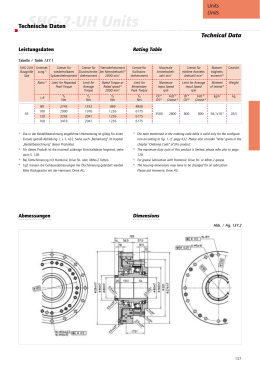
Technical
Data
KR 15/2
Maße / Dimensions: mm
KR 15/2
Störkantenradius des Anbauflansches
Interference radius of the mounting flange
Zusatzlast
Supplementary load
Traglast
Payload
600
Z
140
120
155
--185˚
+70˚
650
1945
--55˚
R 1570
Y
150
--210˚
+115˚
675
1480
1325
Draufsicht
Plan view
300
852
+185˚
219
892
1570
88
262
”Y”
”Z”
Traglast / Payload:
15 kg
Zusatzlast / Supplementary load:
10 kg
Max. Gesamtlast / Total distributed load:
25 kg
Anzahl der Achsen / Number of axes:
6
Handvariante / Wrist variant:
Zentralhand / In--line wrist
Anbauflansch A6 / Mounting flange A6:
DIN ISO 9409--1--A50
Einbaulage / Mounting position:
variabel / variable
Wiederholgenauigkeit / Repeatability:
± 0,1 mm
Steuerung / Controller:
KR C2
Gewicht (ohne Steuerung) ca. / Weight (excl. controller) approx.:
222 kg
Arbeitsraumvolumen / Work envelope volume:
13,1 m3
Achsdaten / Axis data:
Bereich (Software) / Range (software)
Geschwindigkeit / Speed
Achse / Axis 1 (A1)
Achse / Axis 2 (A2)
Achse / Axis 3 (A3)
Achse / Axis 4 (A4)
Achse / Axis 5 (A5)
Achse / Axis 6 (A6)
± 185°
+ 115° /-- 55°
+ 70° /-- 210°
± 350°
± 135°
± 350°
152° /s
152° /s
152° /s
284° /s
293° /s
604° /s
1)
1) Bezogen auf Schnittpunkt Achse 4/5. / Referred to intersection of axes 4 and 5.
RoMeDBKR15--02.96.02
2) Fundamentring nicht erforderlich. / Mounting ring not necessary.
D
Antriebssystem elektro--mech. mit bürstenlosen AC--Servomotoren. / Drive system electromechanical, with brushless AC servomotors.
D
Wegmeßsystem digital--absolut. / Position sensing system digital--absolute.
Angaben über die Beschaffenheit und Verwendbarkeit der Produkte stellen keine Zusicherungen von Eigenschaften dar, sondern dienen lediglich Informationszwecken. Maßgeblich für den Umfang unserer Lieferungen
und Leistungen ist der jeweilige Vertragsgegenstand. / Specifications regarding the quality and usability of the
products do not constitute a warranty of properties. They are intended to serve informative purposes only. Solely
the respective contract of sale shall be binding in respect of the extent of our supplies and services.
www.kuka.com
E
6
KUKA Roboter GmbH, Germany
Lochbild für Zusatzlast
Attachment holes for supplementary load
WM--Nr. 841612--18/D+E/5/08.03
Anbauflansch A6
Mounting flange A6
70
Mitte A3
ø98
6
ø63 h7
M6 (7x)
9 tief
9 deep
ø31,5 H7
140
bis Mitte A5
to center A5
18 tief
18 deep
M6 (4x)
167
6 H7 (1x)
6 tief
6 deep
50
145
center line
2)
Scaricare