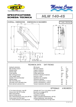
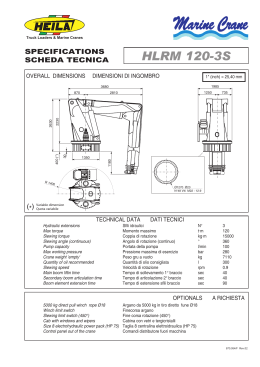
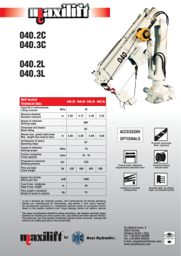
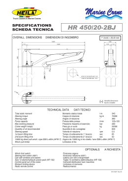
73661-N
GROVE RT875E 15-11-06.qxp:73661-N GROVE RT875E 15-11-06.qxp
27/02/07
17:04
Page 1
RT875E
product
guide
68 t
39 m
10-17 m
60 m
Rough Terrain Crane • Geländekran • Grue Tout-Terrain
Grúa Todo Terreno • Autogru Fuoristrada
73661-N
GROVE RT875E 15-11-06.qxp:73661-N GROVE RT875E 15-11-06.qxp
27/02/07
17:04
Page 2
Contents • Inhalt • Contenu • Contenido • Contenuto
2
Specification
Technische Daten
Caractéristiques techniques
Características
Caratteristiche
3
4
5
6
7
Data • Daten • Caractéristiques • Datos • Dati
8
Dimensions • Abmessungen • Encombrement • Dimensiones • Dimensioni
9
Load charts • Traglasten • Capacités de levage • Capacidades • Capacità
Notes • Hinweise • Notes • Notas • Note
Working Range • Arbeitsbereiche • Diagramme de levage • Gama de trabajo • Area di lavaro
Telescopic Boom • Teleskopausleger • Flèche principale • Pluma telescópica • Braccio telescopico
Swingaway • Klappspitze • Extension treillis • Plumín • Falcone
10
11
12
16
Load handling • Lastaufnahmemittel • Manipulation de charges •
Manipulacíon de cargas • Movimentazione del carico
18
Notes • Hinweise • Notes • Notas • Note
21
23
Symbols • Symbolerklärung • Glossaire des symboles • Glosario de simbolos • Glossario dei simboli
Manitowoc Crane CARE is the Manitowoc Crane Group’s unparalleled product support organisation. Manitowoc Crane CARE combines all aspects of parts, service, technical documentation,
technical support and training into one organisation. The program includes all of the Manitowoc Crane Group’s brands, which include, Potain, Grove, Manitowoc and National Crane.
For the care of your crane and the prosperity of your business, Manitowoc Crane CARE is your single source for customer support. Wherever, whenever, whatever – we’re there.
RT875E
Manitowoc Crane CARE vereint alle Serviceleistungen der Manitowoc Crane Group im Produktsupport vor und nach dem Verkauf: Ersatzteile, Service, technische Dokumentation, technischer
Support und Schulung, alles unter einem Dach. Dieser Service erstreckt sich auf alle Marken der Manitowoc Crane Group: Potain, Grove, Manitowoc und National Crane.
Damit Ihr Kran leistungsfähig bleibt und Ihr Erfolg gesichert ist, bietet Ihnen Manitowoc Crane CARE einen umfassenden Support aus einer Hand. Zu jeder Zeit, an jedem Ort, für jeden Fall – wir
sind für Sie da.
Organisation hors pair dédiée au support technique des produits de Manitowoc Crane Group, Manitowoc Crane CARE réunit au sein d’une même entité tous les aspects du service : pièces de
rechange, service après-vente, publication technique, assistance technique et formation. Ce programme s’adresse à toutes les marques de Manitowoc Crane Group : Potain, Grove, Manitowoc et
National Crane.
Pour assurer l’entretien de vos grues et la prospérité de votre entreprise, Manitowoc Crane CARE constitue votre unique interlocuteur du service à la clientèle. Où que vous soyez, quel que soit
votre besoin, vous pouvez toujours compter sur nous !
Manitowoc Crane CARE, es la organización post-venta y soporte técnico de Manitowoc Crane Group. Manitowoc Crane CARE combina todos los aspectos de piezas de repuesto, servicio,
documentación técnica, apoyo técnico y formación en un único lugar. El programa también incluye todas las ramas Manitowoc Crane Group que engloba Potain, Grove, Manitowoc y National
Crane.
Para el cuidado de su grúa y la prosperidad de su negocio, Manitowoc Crane CARE, es la forma más sencilla de ayudarle. Donde sea y cuando sea, nosotros estamos allí.
Manitowoc Crane CARE è l’ineguagliabile organizzazione di supporto di Manitowoc Crane Group. Manitowoc Crane CARE gestisce tutte le attività legate a pezzi di ricambio, documentazione tecnica,
assistenza tecnica e formazione riunite in un unico punto di riferimento. Questo servizio è attivo per tutti i marchi di Manitowoc Crane Group e precisamente Potain, Grove, Manitowoc e National
Crane.
Per l’assistenza delle Vostre gru e per la redditività dei Vostri investimenti, Manitowoc Crane CARE è l’insostituibile Vostra risorsa. In ogni posto, tutte le volte, per qualsiasi necessità – noi ci siamo
73661-N
GROVE RT875E 15-11-06.qxp:73661-N GROVE RT875E 15-11-06.qxp
27/02/07
17:04
Page 3
Specification
Boom
12,6 m - 39,0 m four-section, sequenced synchronized full power boom.
Maximum tip height: 41,9 m.
Lattice Extension
10.0 m-17 m offsettable bifold lattice swingaway extension. Offsets 0˚, 20˚,
and 40˚. Stows alongside base boom section. Maximum tip height: 58,6 m.
*Optional Lattice Extension Inserts
2 x 6.1 m lattice extension inserts. Installs between the boom nose and
bifold extension, non-stowable.
Maximum tip height: 70.6 m.
Boom Nose
Four nylatron sheaves mounted on heavy-duty tapered roller bearings with
removable pin-type rope guards. Quick-reeving type boom nose.
Removable auxiliary boom nose with removable pin type rope guard.
Boom Elevation
One double-acting hydraulic cylinder with integral holding valve provides
elevation from -3° to +78°.
Load Moment & Anti-Two Block System
Standard “Graphic Display” load moment and anti-two block system with
audio-visual warning and control lever lockout. These systems provide
electronic display of boom angle, length, radius, tip height, relative load
moment, maximum permissible load, load indication and warning of
impending two-block condition. The standard Work Area Definition System
allows the operator to pre-select and define safe working areas. If the
crane approaches the pre-set limits, audio-visual warnings aid the operator
in avoiding job-site obstructions.
Cab
Full-vision, all-steel fabricated with acoustical lining and tinted safety glass
throughout. Cab tilts to +20 degrees. Deluxe seat incorporates armrestmounted hydraulic single-axis controllers. Dash panel incorporates gauges
for all engine functions. Other standard features include: hot water heater,
cab circulating air fan, sliding side and rear windows, sliding skylight with
electric wiper and sunscreen, electric windshield wash/wipe, fire
extinguisher and seat belt.
Swing
Two speed, planetary swing drive with foot-applied multi-disc wet brake.
Spring applied, hydraulically-released swing brake. Single position
mechanical house lock, operated from cab.
Maximum speed: 2.0 RPM.
Counterweight
8 168 kg. Hydraulically installed and removed.
Hydraulic System
Two main pumps ([1] piston and [1] gear) with a combined capacity of
133 GPM (503 LPM). Maximum operating pressure: 277,7 bar. Three
section pressure compensated valve bank. Return line type filter with full
flow by-pass protection and service indicator. Replaceable cartridge with
micron filtration rating of 5/12/16. 995 l. hyd. reservoir. Carrier mounted
oil cooler with thermostatically controlled hydraulic motor driven fan/air
to oil. System pressure test ports.
Hoist Specifications (HP30-19G)
Main and Auxiliary Hoist
Carrier
Chassis
Box section frame fabricated from high-strength, low alloy steel. Front/rear
towing and tie down lugs.
Outriggers
Four hydraulic telescoping single-stage double box beam outriggers with
inverted jacks and integral holding valves. Three position setting, 0%, 50%
and fully extended. All steel fabricated, quick-release type round outrigger
floats, 775 mm diameter. Maximum outrigger pad load: 56 700 kg.
3
Outrigger Controls
Controls and crane level indicator located in cab.
Engine (Tier III)
Cummins QSB 6.7L diesel, six cylinders, 205 kW (Gross) @ 2,500 rpm.
Maximum torque: 987 Nm at 1,500 RPM.
Fuel Tank Capacity
273 l.
Transmission
Full rangeshift with 6 forward and 6 reverse speeds.
Front axle disconnect for 4 x 2 travel.
Electrical System
Two 12-V maintenance free batteries. 12-V starting and lighting. Battery
disconnect. CanBus Diagnostic system.
Drive / Steering
4x4
Fully independent power steering:
Front: Full hydraulic, steering wheel controlled.
Rear: Full hydraulic, switch controlled.
Provides infinite variations of 4 main steering modes:
Front only, rear only, crab and coordinated. Rear steer indicator. Turning
radius: 7,5 m
Axles
Front: Drive/steer with differential and planetary reduction hubs
rigid-mounted to frame.
Rear: Drive/steer with differential and planetary reduction hubs
pivot-mounted to frame.
Oscillation Lockouts
Automatic full hydraulic lockouts on rear axle permits 25,4 cm oscillation
only with boom centered over the front.
Brakes
Full hydraulic split circuit brakes operating on all wheels. Spring-applied,
hydraulically released parking brake mounted on front axle.
Tyres
Std. 29.5 x 25 - 34 bias ply, General.
Lights
Full lighting including turn indicators, head, tail, brake and hazard warning
lights.
Maximum Speed
35 kmph.
Gradeability (Theoretical)
Planetary reduction with automatic spring applied multi-disc wet brake.
Electronic hoist drum rotation indicators and hoist drum cable followers.
Maximum Single Line Pull:
1st layers: 9 185 kg
3rd layer: 7 715 kg
5th layer: 6 650 kg
Maximum Permissible Line Pull:
7 620 kg with 6 x 37 class rope
7 620 kg with 35 x 7 class rope
Maximum Single Line Speed: 514 FPM (156 m/min)
Rope Construction: 6 x 36 EIPS IWRC, Special Flexible
35 x 7 Flex-X, Rotation Resistant
Rope Diameter: 19 mm
Rope Length: Main Hoist: 182.8 m Auxiliary Hoist: 182.8m
Maximum Rope Stowage: 256 m
75% (Based on 49 119 kg GVW) 29.5 x 25 tires, 39,0 m boom, plus 17,0 m
swingaway, 8 165 kg counterweight, 75t hookblock and 10t headache
ball).
*Denotes optional equipment
*Denotes optional equipment
Miscellaneous Standard Equipment
Full width steel fenders, full length aluminium decking, dual rear view
mirrors, hookblock tiedown, electronic back-up alarm, light package, front
stowage well, tachometer/hourmeter, rear wheel position indicator, 36,000
BTU hot water cab heater, hoist mirrors, engine distress A/V warning
system, front/rear tie down and two lugs, coolant sight level indicator.
*Optional Equipment
*Auxiliary Lighting Package (includes cab mounted amber flashing light,
hoist mounted work light, and dual base boom mounted floodlights.)
*LMI light bar (in cab) *Air Conditioning (28,500 BTU) *360 degree NYC
style mechanical swinglock *Rear Pintle hook *Cab controlled cross axle
differential locks, (front and rear) *PAT data logger *Rubber mat for
stowage trough
RT875E
Superstructure
73661-N
GROVE RT875E 15-11-06.qxp:73661-N GROVE RT875E 15-11-06.qxp
27/02/07
17:04
Page 8
Data • Daten • Caractéristiques • Datos • Dati
8
Axle
Achse
Essieu
Eje
Asse
t
1
2
Total weight
Gesamtgewicht
Poids total
Peso total
Peso totale
24,5
24,6
49,1
Lifting Capacity
Traglast
Force de levage
Capacidad de elevación
Capacità di sollevamento
Sheaves
Rollen
Poulies
Poleas
Carrucole
Parts of line
Stränge
Brins
Ramales de cable
Numero di funi
Weight
Gewicht
Poids
Peso
Peso
68 t
5
9
725 kg
9t
H/B (swivel)
1
257 kg
+
Infinitely variable
stufenlos
progressivement variable
Infinitamente variable
Infinitamente variabile
Rope
Seil
Câble
Cable
Fune
0 - 156 m/min
single line
für einfachen Strang
brin simple
ramal simple
tiro a fune singola
19 mm/182 m (6x37 class)
19 mm/182 m (35x7 class)
7620 kg
7620 kg
0 - 156 m/min
single line
für einfachen Strang
brin simple
ramal simple
tiro a fune singola
19 mm/182 m (35x7 class)
7620 kg
-3° to 78°
12,6 m to 39,0 m
* Required for 5:1 Rope F.O. S., Gefordert bei 5:1 Sicherheitsfaktor am Hubseil, Nécessaire pour coefficient de sécurité de 5:1 du câble de levage,
Necesario para el factor de seguridad de 5 a 1 del cable cabrestante, Necessario per un coefficiente di sicurezza 5:1 della fune di sollevamento.
RT875E
Max. permissible line pull
Maximal zulässige Seilzugkraft
Effort maximum autorisé sur brin simple
Potencia máxima admisible por ramal
Tiro massimo ammissibile della fune
GROVE RT875E 15-11-06.qxp:73661-N GROVE RT875E 15-11-06.qxp
27/02/07
17:04
Page 9
Dimensions • Abmessungen • Encombrement • Dimensiones • Dimensioni
9
Note: Reference dimensions in mm • Hinweis: Bezugsmaße in mm • Remarque : cotes de référence en mm •
Nota: Dimensiones de referencia en mm • Nota: Dimensioni di riferimento in mm
RT875E
73661-N
73661-N
GROVE RT875E 15-11-06.qxp:73661-N GROVE RT875E 15-11-06.qxp
27/02/07
17:04
Page 10
Load charts • Traglasten • Capacités de levage • Capacidades • Capacità
Notes • Hinweise • Notes • Notas • Note
Lifting capacities according to DIN/ISO • 85%
10
Warning: THIS CHART IS ONLY A GUIDE. The Notes below are for illustration only and should not be relied upon to operate the crane.
The individual crane’s load chart, operating instructions and other instruction plates must be read and understood prior to operating the crane.
DIN/ISO: The mechanical strength complies with DIN 15018, part 3. Tipping conditions are governed by DIN 15019, part 2 and ISO 4305 standards.
They also take into account the requirements of prEN 13000: 2003 and therefore comply with the requirements of the EU machinery directive.
85%: Capacities are in accordance with SAE J1063 and do not exceed 85% of the tipping load (SAE J1289 for outriggers 50% and 0% extended) as determined by SAE J765.
1. Capacities given do not include the weight of hookblocks, slings, auxiliary lifting equipment and load handling devices. Their weights MUST be added to the load to be lifted. When more than minimum required
reeving is used, the additional rope weight shall be considered part of the load.
2. All capacities are for crane on firm, level surface. It may be necessary to have structural supports under the outrigger floats or tyres to spread the load to a larger bearing surface.
3. When either boom length or radius or both are between values listed, the smallest load shown at either the next larger radius or boom length shall be used.
4. For outrigger operation, ALL outriggers shall be fully extended with tyres raised free of ground before raising the boom or lifting loads.
5. Tyres shall be inflated to the recommended pressure before lifting on rubber.
Traglasten entsprechen DIN/ISO • 85%
WARNUNG: DIESE TABELLE IST LEDIGLICHE EINE RICHTLINIE. Die Hinweise dienen als Erklärung und sind für die Kranbedienung nicht maßgebend. Vor Inbetriebnahme des
Kranes sind Traglasttabellen, Bedienungsanleitung und andere Vorschriften eingehend zu studieren.
DIN/ISO: Der Festigkeitsberechnung liegen die DIN 15018 Teil 3 zugrunde. Die Traglasten im Standsicherheitsbereich entsprechen DIN 15019 Teil 2 und ISO 4305. Sie berücksichtigen außerdem die
Forderungen von prEN 13000: 2003 und entsprechen damit den Anforderungen der Maschinenrichtlinie.
85%: Tragkraftwerte entsprechen SAE J1063 und überschreiten nicht 85 % der Kipplast (SAE J1289 bei halb- bzw. ganz ausgefahrener Abstützung) gemäß Richtlinien SAE J 765.
1. Das Gewicht der Hakenflaschen und aller Anschlagmittel muß zu der Last hinzugerechnet werden. Beim Einscheren mit erhöhten Werten ist das zusätzliche Seilgewicht als Teil der Last zu betrachten.
2. Alle Werte gelten für den Kran auf festem, ebenem Untergrund. Eventuell müssen die Stützteller oder Reifen unterlegt werden, um die Last über eine größere Abstützfläche zu verteilen.
3. Wenn Auslegerlänge oder Radius oder beide Werte zwischen den aufgeführten Werten liegen, ist die geringere der Traglasten zu wählen, die für den die nächstgrößere Ausladung oder die nächste bzw.
anschließende Auslegerlänge genannt sind.
4. In abgestütztem Zustand müssen ALLE Stützen komplette ausgefahren sein. Die Reifen dürfen den Boden nicht berühren. Erst danach dürfen Lasten oder der Ausleger angehoben werden.
5. Bevor frei auf Rädern gearbeitet wird, müssen, die Reifen mit dem vorschriftsmäßigen Druck aufgefüllt werden.
Capacités de levage selon DIN/ISO • 85%
ATTENTION: CE TABLEAU N’EST QU’UN GUIDE. Les notes ci-dessous sont données à titre d’exemple et ne devront pas être utilisées pour faire fonctionner la grue. Toute la
documentation concernant chaque type de grue: tableau des charges, instructions de fonctionnement et toutes autres plaques d’instructions devront être lues et comprises
avant de manoeuvrer la grue.
DIN/ISO:
Les limites du basculement sont conformes à la norme DIN 15019 section 2 et ISO 4305. Elles tiennent également compte des paramètres établis pour le projet de norme Européenne prEN 13000:
2003 et de ce fait satisfont les exigences de la Directive Européenne Machines.
85%: Les capacités de levage sont conformes à la norme SAE J1063 et ne dépassent pas 85% de la charge de basculement (SAE J1289 pour les poutres de calage déployées à 50% et 0%) tel que cela est
prescrit par la norme SAE J765.
1. Les charges mentionnées dans les tableaux ne comprennent pas le poids des moufles, des élingues et autres accessoires de levage qui doit être additionné à celui de la charge levée. Lorsque le mouflage est
supérieur au minimum requis le poids de l’excédent de câble doit être additionné à celui de la charge.
2. Les capacités sont données sur sol ferme et de niveau. Il peut être nécessaire d’utiliser des bastaings ou des accessoires similaires afin de répartir la charge transmise au sol par les roues ou les patins de
calage.
3. Lorsque la longueur de flèche ou la portée ne correspond pas aux valeurs mentionnées dans les tableaux, il convient de se référer à la valeur inférieure mentionnée pour la portée ou la longueur de flèche
immédiatement supérieure.
4. Pour utilisation machine calée, les poutres de calage doivent être totalement télescopées et les roues décollées du sol avant de relever la flèche ou de lever des charges.
5. Les pneumatiques devront être gonflés aux pressions préconisées avant tout levage en libre.
Capacidades de elevación de acuerdo con DIN/ISO • 85%
AVISO: ESTA TABLA ES SOLO UNA ORIENTACION. Las notas que aparecen al final de la misma solo sirven de ilustración y no deben ser tomadas como instrucciones para
operar la grúa. La tabla de cargas, las instrucciones de operación y otras placas ilustrativas de cada grúa deben ser leídas y correctamente interpretadas antes de operar la
grúa.
DIN/ISO: Los analisis de resistencia están basados en las normas DIN 15018. Apartados 3. Las condiciones de vuelco están reguladas por las normas
DIN 15019 apartado 2 y ISO 4305. Tienen tambien cuenta de las exigencias establecidas por prEN 13000: 2003 y asi cumplen con los requerimientos da las Directivas de Maquinaria UE.
85%: Capacidades de acuerdo con las Normas SAE J1063 y no exceden del 85% del momento de vuelco (Normas SAE J1289 para las cargas sobre estabilizadores extendidos al 50% o sin extender 0%)
como fijan las normas SAE J765.
1. Las cargas indicadas no incluyen el péso de los ganchos, eslíngas, equipos auxiliares y aparejos de elevación. Sus pesos DEBEN ser añadidos al de la carga a elevar. Cuando se utilice un número de ramales de
cable superior al necesario, el peso adicional del cable debe ser considerado como parte de la carga.
2. Todas las capacidades corresponden a la grúa situada sobre torreno firme nivelado y uniforme. La naturaleza del terreno puede hacer necesario colocar, bajo los apoyos de los estabilizadores o bajo los
neumáticos, elementos estructurales que repartan la carga sobre una mayor superficie de apoyo.
3. Cuando se trabaje con longitudes de pluma o rádios, intermedios entre los valores reflejados en las tablas, se considerará la carga inmediata inferior indicada en el radio o longitud de pluma inmediato superior.
4. Para trabajos sobre estabilizadores, TODOS los estabilizadores estarán totalmente extendidos y los neumáticos sin tocar el suelo antes de elevar pluma o izar cargas.
5. Los neumáticos deberán estar inflados a la presión recomendada antes de elevar cargas sobre neumáticos.
RT875E
Capacità di sollevamento in accordo con DIN/ISO • 85%
ATTENZIONE: QUESTA TABELLA E’ SOLO UNA GUIDA. Le note qui sotto riportate sono date a titolo d’esempio e non devono essere utilizzate per far funzionare la gru.
La tabella di carico, le istruzioni d’uso ed ogni altro foglio illustrativo devono essere letti e compresi prima di manovrare la gru.
DIN/ISO: il calcolo di resistenza è basato sulle norme DIN 15018, parte 3. Le condizioni di ribaltamento sono regolate dalle norme DIN 15019 parte 2 e ISO 4305. Esse tengono conto anche dei parametri
stabiliti da prEN13000: 2003 e quindi soddisfano le richieste della Direttiva Macchine Europea.
85%: Le capacità di sollevamento sono conformi alla norma SAE J1063 e non superano l’85% del carico di ribaltamento (SAE J1289 per gli stabilizzatori estesi al 50% e 0%) come prescritto dalla norma
SAE J765.
1. I carichi indicati nelle tavole non comprendono il peso dei ganci, dei tiranti, e di nessun altro accessorio di sollevamento che deve essere aggiunto a quello del carico sollevato. Quando il numero di funi è
superiore al minimo richiesto il peso addizionale della fune deve essere aggiunto a quello del carico.
2. Tutte le capacità si intendono per la gru situata su un terreno compatto livellato e uniforme. Potrebbe rendersi necessario utilizzare dei supporti strutturali, sotto gli appoggi degli stabilizzatori o sotto i
pneumatici, per ripartire il carico su una superficie di appoggio maggiore.
3. Quando la lunghezza del braccio o la portata non corrispondono ai valori riportati nelle tabelle, conviene considerare il valore inferiore riportato per il raggio di lavoro o la lunghezza del braccio immediatamente
superiore.
4. Per lavoro su stabilizzatori, TUTTI gli stabilizzatori devono essere completamente estesi e i pneumatici staccati da terra prima di rialzare il braccio o di sollevare carichi.
5. I pneumatici devono essere gonfiati alla pressione raccomandata prima di sollevare carichi sopra i pneumatici.
GROVE RT875E 15-11-06.qxp:73661-N GROVE RT875E 15-11-06.qxp
27/02/07
17:04
Page 11
Load charts • Traglasten • Capacités de levage • Capacidades • Capacità
Working range bi-fold extension • Arbeitsbereiche mit Doppel-Klappspitze
Portée de travail de l'extension à double repliage latéral • Radio de trabajo para extensión de doble pliegue
Area di lavoro con prolunga ripiegabile
11
Hook block • Unterflasche • Crochet-moufle • Gancho • Gancio
(t)
H
(mm)
68
3020
THIS CHART IS ONLY A GUIDE AND SHOULD NOT BE USED TO OPERATE THE CRANE. The individual crane’s load chart, operating instructions and other instructional plates must be read and understood prior to operating the crane.
DIE DATEN IN DIESER TABELLE DIENEN NUR ZUR INFORMATION UND GELTEN NICHT FÜR DEN BETRIEB DES KRANS. Vor Inbetriebnahme des Krans sind dessen jeweilige Traglasttabelle, Betriebsanleitung und weitere Herstelleranleitungen durchzulesen und zu befolgen.
CETTE ILLUSTRATION EST FOURNIE A SIMPLE TITRE INDICATIF. NE L'UTILISEZ PAS POUR MANŒUVRER LA GRUE. La courbe de charge, les notices techniques et autres consignes d'utilisation doivent être lues et assimilées avant toute utilisation de cette grue.
ESTA TABLA ES MERAMENTE ORIENTATIVA Y NO DEBERÁ UTILIZARSE PARA TRABAJAR CON LA GRÚA. Antes de utilizar la grúa, han de leerse y entenderse la tabla de cargas individuales de la grúa, las instrucciones de funcionamiento y otras placas de instrucciones.
QUESTO GRAFICO SERVE SOLO DA GUIDA E NON DEVE ESSERE UTILIZZATO PER OPERARE CON LA GRU. Il grafico di carico, le istruzioni operative e altre targhe d’istruzione della gru individuale devono essere letti e compresi prima di azionare la gru.
RT875E
73661-N
73661-N
GROVE RT875E 15-11-06.qxp:73661-N GROVE RT875E 15-11-06.qxp
27/02/07
17:04
Page 12
Load charts • Traglasten • Capacités de levage • Capacidades • Capacità
Telescopic boom • Teleskopausleger • Flèche principale • Pluma telescópica • Braccio telescopico
100 %
8,165 t
360˚
RT875E
DIN/ISO
12
Radius m
12,6
3,0
3,5
4,0
4,5
5,0
6,0
7,0
8,0
9,0
10,0
12,0
14,0
16,0
18,0
20,0
22,0
24,0
26,0
28,0
30,0
32,0
34,0
36,0
++70,000
+68,025
64,625
59,675
55,125
46,075
39,750
32,775
25,650
15,975
15,2
18,3
56,225
56,225
56,225
56,225
53,150
45,975
38,600
30,925
25,200
20,475
14,375
47,850
47,850
47,575
47,225
44,850
39,475
35,350
28,800
23,850
20,200
14,275
10,500
5,500
21,4
26,975
26,975
26,975
26,975
26,325
25,000
22,450
19,000
14,050
10,300
7,725
5,855
24,4
19,075
19,075
19,075
19,075
19,075
19,075
18,075
14,225
10,825
8,335
6,480
5,080
3,125
27,4
19,050
19,050
19,050
18,700
17,825
16,450
13,825
11,150
8,675
6,835
5,415
4,300
3,405
30,5
17,975
17,975
17,575
16,525
15,150
12,650
10,825
9,020
7,145
5,730
4,610
3,695
2,950
2,120
33,5
14,475
14,475
14,475
13,800
11,800
10,075
8,720
7,340
5,930
4,825
3,925
3,180
2,555
2,025
36,6
39,0
11,675
11,675
11,675
10,925
9,530
8,210
7,145
6,125
5,020
4,135
3,400
2,775
2,245
1,790
1,395
9,975
9,975
9,975
9,975
9,170
7,880
6,830
5,985
5,160
4,275
3,550
2,930
2,405
1,950
1,555
1,210
A6-829-103682
12,6 - 39,0m
+ 9 parts line required to lift this capacity (using aux. boom nose). refer to Operator’s & Safety Handbook for reeving diagram.
++ 9 parts line of Flex-X35 cable only required to lift this capacity (using aux. boom nose).
RT875E
Radius m
12,6
3,0
3,5
4,0
4,5
5,0
6,0
7,0
8,0
9,0
10,0
12,0
14,0
16,0
18,0
20,0
22,0
24,0
26,0
28,0
30,0
32,0
34,0
36,0
++70,000
+68,025
64,625
59,675
55,125
46,075
39,750
34,800
27,650
15,975
15,2
18,3
56,225
56,225
56,225
56,225
53,150
45,975
39,625
34,450
27,200
22,200
15,700
47,850
47,850
47,575
47,225
44,850
39,475
35,350
31,750
27,075
22,075
15,625
11,600
5,500
21,4
26,975
26,975
26,975
26,975
26,325
25,000
22,675
20,675
15,400
11,425
8,675
6,690
24,4
19,075
19,075
19,075
19,075
19,075
19,075
18,075
15,550
11,950
9,295
7,325
5,835
3,125
27,4
19,050
19,050
19,050
18,700
17,825
16,450
13,825
11,875
9,635
7,680
6,170
4,985
4,035
30,5
17,975
17,975
17,575
16,525
15,150
12,650
10,825
9,425
7,990
6,485
5,295
4,325
3,530
2,120
33,5
14,475
14,475
14,475
13,800
11,800
10,075
8,720
7,610
6,680
5,510
4,550
3,760
3,095
2,530
36,6
39,0
11,675
11,675
11,675
10,925
9,530
8,210
7,145
6,275
5,540
4,760
3,980
3,315
2,755
2,270
1,395
9,975
9,975
9,975
9,975
9,170
7,880
6,830
5,985
5,290
4,690
4,130
3,475
2,915
2,430
2,015
1,645
A6-829-103676
RT875E
85 %
+ 9 parts line required to lift this capacity (using aux. boom nose). refer to Operator’s & Safety Handbook for reeving diagram.
++ 9 parts line of Flex-X35 cable only required to lift this capacity (using aux. boom nose).
THIS CHART IS ONLY A GUIDE AND SHOULD NOT BE USED TO OPERATE THE CRANE. The individual crane’s load chart, operating instructions and other instructional plates must be read and understood prior to operating the crane.
DIE DATEN IN DIESER TABELLE DIENEN NUR ZUR INFORMATION UND GELTEN NICHT FÜR DEN BETRIEB DES KRANS. Vor Inbetriebnahme des Krans sind dessen jeweilige Traglasttabelle, Betriebsanleitung und weitere Herstelleranleitungen durchzulesen und zu befolgen.
CETTE ILLUSTRATION EST FOURNIE A SIMPLE TITRE INDICATIF. NE L'UTILISEZ PAS POUR MANŒUVRER LA GRUE. La courbe de charge, les notices techniques et autres consignes d'utilisation doivent être lues et assimilées avant toute utilisation de cette grue.
ESTA TABLA ES MERAMENTE ORIENTATIVA Y NO DEBERÁ UTILIZARSE PARA TRABAJAR CON LA GRÚA. Antes de utilizar la grúa, han de leerse y entenderse la tabla de cargas individuales de la grúa, las instrucciones de funcionamiento y otras placas de instrucciones.
QUESTO GRAFICO SERVE SOLO DA GUIDA E NON DEVE ESSERE UTILIZZATO PER OPERARE CON LA GRU. Il grafico di carico, le istruzioni operative e altre targhe d’istruzione della gru individuale devono essere letti e compresi prima di azionare la gru.
GROVE RT875E 15-11-06.qxp:73661-N GROVE RT875E 15-11-06.qxp
27/02/07
17:04
Page 13
Load charts • Traglasten • Capacités de levage • Capacidades • Capacità
Telescopic boom • Teleskopausleger • Flèche principale • Pluma telescópica • Braccio telescopico
12,6 - 39,0m
50 %
8,165 t
360˚
RT875E
DIN/ISO
Radius m
12,6
3,0
3,5
4,0
4,5
5,0
6,0
7,0
8,0
9,0
10,0
12,0
14,0
16,0
18,0
20,0
22,0
24,0
26,0
28,0
30,0
32,0
+67,350
59,950
53,375
47,450
41,425
31,000
24,400
19,475
15,525
12,625
15,2
18,3
56,225
56,225
52,675
44,850
38,075
28,850
22,825
18,600
15,225
12,475
8,710
47,850
47,850
47,325
40,850
34,925
26,700
21,275
17,425
14,500
12,225
8,625
6,155
4,420
21,4
26,975
26,975
26,975
24,850
19,900
16,325
13,650
11,525
8,410
6,005
4,250
2,950
24,4
19,075
19,075
19,075
19,075
16,175
13,625
11,625
8,645
6,530
4,820
3,545
2,560
1,780
27,4
19,050
19,050
19,050
15,950
13,525
11,600
8,760
6,720
5,190
3,885
2,880
2,085
1,435
30,5
17,975
17,975
15,675
13,375
11,525
8,785
6,840
5,355
4,200
3,190
2,375
1,715
1,170
0,710
13
33,5
36,6
39,0
14,475
14,475
13,175
11,400
8,770
6,880
5,460
4,335
3,405
2,595
1,935
1,390
0,930
0,540
11,675
11,675
11,250
8,715
6,880
5,500
4,415
3,530
2,800
2,145
1,600
1,145
0,750
9,975
9,975
9,975
8,665
6,875
5,525
4,470
3,605
2,885
2,290
1,750
1,295
0,905
0,570
A6-829-103677
+ 9 parts line required to lift this capacity (using aux. boom nose). refer to Operator’s & Safety Handbook for reeving diagram.
12,6 - 39,0m
0%
8,165 t
360˚
RT875E
DIN/ISO
Radius m
3,0
3,5
4,0
4,5
5,0
6,0
7,0
8,0
9,0
10,0
12,0
14,0
16,0
18,0
20,0
22,0
12,6
15,2
18,3
21,4
39,875
32,500
27,175
23,150
20,000
15,425
12,275
9,955
7,870
6,235
36,000
29,675
25,050
21,450
18,600
14,375
11,400
9,220
7,525
6,110
3,940
32,400
26,950
22,875
19,725
17,200
13,350
10,600
8,545
6,940
5,660
3,750
2,365
1,275
21,025
18,175
15,900
12,425
9,900
7,955
6,440
5,220
3,385
2,070
1,090
24,4
27,4
17,675
15,550
12,300
9,955
8,130
6,670
5,495
3,710
2,425
1,455
0,705
15,150
12,125
9,885
8,170
6,795
5,660
3,930
2,675
1,725
0,980
30,5
11,875
9,775
8,140
6,835
5,765
4,090
2,865
1,935
1,2000
0,615
33,5
9,630
8,065
6,815
5,795
4,190
3,000
2,090
1,370
0,790
36,6
7,960
6,760
5,770
4,245
3,085
2,195
1,490
0,920
39,0
7,870
6,710
5,750
4,265
3,145
2,270
1,575
1,010
0,545
A6-829-103678
RT875E
73661-N
73661-N
GROVE RT875E 15-11-06.qxp:73661-N GROVE RT875E 15-11-06.qxp
27/02/07
17:04
Page 14
Load charts • Traglasten • Capacités de levage • Capacidades • Capacità
Telescopic boom • Teleskopausleger • Flèche principale • Pluma telescópica • Braccio telescopico
12,6 - 39,0m
14
8,165 t
360˚
RT875E
DIN/ISO
Radius m
3,5
4,0
4,5
5,0
6,0
7,0
8,0
9,0
10,0
12,0
14,0
16,0
12,6
15,2
22,300
20,650
17,725
15,000
10,950
8,280
6,370
4,940
3,825
18,475
17,625
16,300
14,200
10,975
8,270
6,340
4,915
3,815
2,240
18,3
21,4
10,075
7,860
6,100
4,750
3,690
2,125
1,025
9,295
7,305
5,775
4,560
3,500
1,920
0,870
24,4
5,965
4,800
3,850
2,395
1,330
0,505
27,4
4,940
4,025
2,615
1,535
0,740
A6-829-103683
RT875E
85 %
Radius m
3,5
4,0
4,5
5,0
6,0
7,0
8,0
9,0
10,0
12,0
14,0
16,0
12,6
15,2
22,300
21,100
19,325
17,375
12,775
9,760
7,600
5,985
4,725
18,475
17,625
16,375
14,800
12,250
9,780
7,595
5,985
4,745
2,955
18,3
12,025
9,335
7,345
5,825
4,625
2,855
1,550
21,4
9,985
9,340
7,400
5,700
4,425
2,640
1,455
24,4
7,250
6,145
4,990
3,235
1,965
1,010
27,4
5,530
5,240
3,395
2,150
1,255
RT875E
A6-829-103679
THIS CHART IS ONLY A GUIDE AND SHOULD NOT BE USED TO OPERATE THE CRANE. The individual crane’s load chart, operating instructions and other instructional plates must be read and understood prior to operating the crane.
DIE DATEN IN DIESER TABELLE DIENEN NUR ZUR INFORMATION UND GELTEN NICHT FÜR DEN BETRIEB DES KRANS. Vor Inbetriebnahme des Krans sind dessen jeweilige Traglasttabelle, Betriebsanleitung und weitere Herstelleranleitungen durchzulesen und zu befolgen.
CETTE ILLUSTRATION EST FOURNIE A SIMPLE TITRE INDICATIF. NE L'UTILISEZ PAS POUR MANŒUVRER LA GRUE. La courbe de charge, les notices techniques et autres consignes d'utilisation doivent être lues et assimilées avant toute utilisation de cette grue.
ESTA TABLA ES MERAMENTE ORIENTATIVA Y NO DEBERÁ UTILIZARSE PARA TRABAJAR CON LA GRÚA. Antes de utilizar la grúa, han de leerse y entenderse la tabla de cargas individuales de la grúa, las instrucciones de funcionamiento y otras placas de instrucciones.
QUESTO GRAFICO SERVE SOLO DA GUIDA E NON DEVE ESSERE UTILIZZATO PER OPERARE CON LA GRU. Il grafico di carico, le istruzioni operative e altre targhe d’istruzione della gru individuale devono essere letti e compresi prima di azionare la gru.
GROVE RT875E 15-11-06.qxp:73661-N GROVE RT875E 15-11-06.qxp
27/02/07
17:04
Page 15
Load charts • Traglasten • Capacités de levage • Capacidades • Capacità
Telescopic boom • Teleskopausleger • Flèche principale • Pluma telescópica • Braccio telescopico
12,6 - 39,0m
4,0 km/h
8,165 t
360˚
RT875E
DIN/ISO
Radius m
3,5
4,0
4,5
5,0
6,0
7,0
8,0
9,0
10,0
12,0
14,0
16,0
18,0
20,0
22,0
24,0
12,6
15,2
26,950
25,300
22,875
21,050
17,550
15,050
12,375
9,945
8,125
22,400
22,400
22,400
20,900
17,425
14,925
12,200
9,745
7,915
5,370
18,3
16,725
14,550
11,950
9,600
7,830
5,365
3,735
2,575
*21,4
24,4
13,475
13,475
11,975
9,750
7,940
5,370
3,665
2,455
1,550
10,050
8,280
5,780
4,090
2,885
1,985
1,290
0,730
15
27,4
6,130
4,425
3,190
2,265
1,550
0,980
0,510
A6-829-103684
12,6 - 39,0m
4,0 km/h
8,165 t
360˚
RT875E
85 %
Radius m
3,5
4,0
4,5
5,0
6,0
7,0
8,0
9,0
10,0
12,0
14,0
16,0
18,0
20,0
22,0
24,0
12,6
15,2
26,950
25,300
22,875
21,050
17,550
15,050
12,950
11,200
9,780
22,400
22,400
22,400
20,900
17,425
14,925
12,800
11,025
9,625
7,240
18,3
16,725
14,550
12,600
10,900
9,560
7,265
4,100
2,975
*21,4
13,475
13,475
12,800
11,075
9,675
7,285
4,040
2,870
1,925
24,4
11,100
9,990
7,745
5,505
3,340
2,420
1,665
1,040
27,4
8,100
5,905
3,670
2,730
1,960
1,330
0,790
A6-829-103680
THIS CHART IS ONLY A GUIDE AND SHOULD NOT BE USED TO OPERATE THE CRANE. The individual crane’s load chart, operating instructions and other instructional plates must be read and understood prior to operating the crane.
DIE DATEN IN DIESER TABELLE DIENEN NUR ZUR INFORMATION UND GELTEN NICHT FÜR DEN BETRIEB DES KRANS. Vor Inbetriebnahme des Krans sind dessen jeweilige Traglasttabelle, Betriebsanleitung und weitere Herstelleranleitungen durchzulesen und zu befolgen.
CETTE ILLUSTRATION EST FOURNIE A SIMPLE TITRE INDICATIF. NE L'UTILISEZ PAS POUR MANŒUVRER LA GRUE. La courbe de charge, les notices techniques et autres consignes d'utilisation doivent être lues et assimilées avant toute utilisation de cette grue.
ESTA TABLA ES MERAMENTE ORIENTATIVA Y NO DEBERÁ UTILIZARSE PARA TRABAJAR CON LA GRÚA. Antes de utilizar la grúa, han de leerse y entenderse la tabla de cargas individuales de la grúa, las instrucciones de funcionamiento y otras placas de instrucciones.
QUESTO GRAFICO SERVE SOLO DA GUIDA E NON DEVE ESSERE UTILIZZATO PER OPERARE CON LA GRU. Il grafico di carico, le istruzioni operative e altre targhe d’istruzione della gru individuale devono essere letti e compresi prima di azionare la gru.
RT875E
73661-N
73661-N
GROVE RT875E 15-11-06.qxp:73661-N GROVE RT875E 15-11-06.qxp
27/02/07
17:04
Page 16
Load charts • Traglasten • Capacités de levage • Capacidades • Capacità
Swingaway • Klappspitze • Extension treillis • Plumin • Falcone
12,6 - 39,0 m
10.0-17.00 m
100%
16
360°
8,165 t
RT875E
DIN/ISO
Radius
in m
10,0
12,0
14,0
16,0
18,0
20,0
22,0
24,0
26,0
28,0
30,0
32,0
34,0
36,0
38,0
40,0
42,0
44,0
46,0
10,0 m
0° offset
5,395
5,395
5,395
5,395
5,065
4,490
4,020
3,620
3,275
2,980
2,725
2,290
1,900
1,555
1,250
0,975
0,725
0,505
Radius
in m
16,0
18,0
20,0
22,0
24,0
26,0
28,0
30,0
32,0
34,0
36,0
38,0
40,0
42,0
44,0
46,0
48,0
20° offset
5,285
4,620
4,155
3,760
3,420
3,130
2,875
2,655
2,455
2,280
2,095
1,720
1,385
1,085
0,820
17,0 m
40° offset
4,080
3,640
3,345
3,085
2,855
2,650
2,475
2,310
2,160
2,030
1,810
0° offset
20° offset
40° offset
2,745
2,745
2,745
2,745
2,745
2,710
2,650
2,515
2,270
2,060
1,870
1,710
1,560
1,430
1,185
0,945
0,725
0,525
2,450
2,400
2,340
2,280
2,100
1,930
1,775
1,635
1,510
1,400
1,290
1,200
1,115
0,920
0,695
2,070
2,010
1,860
1,725
1,605
1,495
1,395
1,305
1,220
1,135
1,065
0° offset
20° offset
40° offset
1,595
1,595
1,595
1,595
1,485
1,295
1,120
0,970
0,840
0,720
0,615
0,520
1,695
1,585
1,395
1,235
1,085
0,950
0,835
0,725
0,630
0,540
1,460
1,195
1,060
0,935
0,830
0,730
0,635
0,550
23,1 m
0° offset
2,200
2,200
2,200
2,200
2,155
1,945
1,730
1,540
1,375
1,230
1,100
0,985
0,880
0,785
0,700
0,545
20° offset
2,220
2,125
1,905
1,710
1,540
1,395
1,255
1,135
1,025
0,925
0,835
0,745
0,670
0,595
0,530
29,2 m
40° offset
1,580
1,440
1,310
1,190
1,085
0,985
0,895
0,815
0,735
0,665
0,595
0,535
A6-829-103699
RT875E
85 %
Radius
RT875E
in m
10,0
12,0
14,0
16,0
18,0
20,0
22,0
24,0
26,0
28,0
30,0
32,0
34,0
36,0
38,0
40,0
42,0
44,0
46,0
48,0
50,0
10,0 m
0° offset
5,395
5,395
5,395
5,395
5,065
4,490
4,020
3,620
3,275
2,980
2,725
2,500
2,300
2,020
1,690
1,400
1,135
0,900
20° offset
5,285
4,620
4,155
3,760
3,420
3,130
2,875
2,655
2,455
2,280
2,120
1,980
1,815
1,495
1,215
A6-829-103696
17,0 m
40° offset
4,140
3,640
3,345
3,085
2,855
2,650
2,475
2,310
2,160
2,030
1,915
0° offset
2,745
2,745
2,745
2,745
2,745
2,745
2,740
2,515
2,270
2,060
1,870
1,710
1,560
1,430
1,310
1,205
1,110
0,910
0,715
0,535
20° offset
2,745
2,665
2,520
2,295
2,100
1,930
1,775
1,635
1,510
1,400
1,290
1,200
1,115
1,035
0,960
0,855
40° offset
2,210
2,010
1,860
1,725
1,605
1,495
1,395
1,305
1,220
1,135
1,065
A6-829-103695
THIS CHART IS ONLY A GUIDE AND SHOULD NOT BE USED TO OPERATE THE CRANE. The individual crane’s load chart, operating instructions and other instructional plates must be read and understood prior to operating the crane.
DIE DATEN IN DIESER TABELLE DIENEN NUR ZUR INFORMATION UND GELTEN NICHT FÜR DEN BETRIEB DES KRANS. Vor Inbetriebnahme des Krans sind dessen jeweilige Traglasttabelle, Betriebsanleitung und weitere Herstelleranleitungen durchzulesen und zu befolgen.
CETTE ILLUSTRATION EST FOURNIE A SIMPLE TITRE INDICATIF. NE L'UTILISEZ PAS POUR MANŒUVRER LA GRUE. La courbe de charge, les notices techniques et autres consignes d'utilisation doivent être lues et assimilées avant toute utilisation de cette grue.
ESTA TABLA ES MERAMENTE ORIENTATIVA Y NO DEBERÁ UTILIZARSE PARA TRABAJAR CON LA GRÚA. Antes de utilizar la grúa, han de leerse y entenderse la tabla de cargas individuales de la grúa, las instrucciones de funcionamiento y otras placas de instrucciones.
QUESTO GRAFICO SERVE SOLO DA GUIDA E NON DEVE ESSERE UTILIZZATO PER OPERARE CON LA GRU. Il grafico di carico, le istruzioni operative e altre targhe d’istruzione della gru individuale devono essere letti e compresi prima di azionare la gru.
GROVE RT875E 15-11-06.qxp:73661-N GROVE RT875E 15-11-06.qxp
27/02/07
17:04
Page 17
Load charts • Traglasten • Capacités de levage • Capacidades • Capacità
Swingaway • Klappspitze • Extension treillis • Plumin • Falcone
12,6 - 39,0 m
10.0-17.00 m
100%
360°
8,165 t
RT875E
85 %
Radius
23,1 m
in m
16,0
18,0
20,0
22,0
24,0
26,0
28,0
30,0
32,0
34,0
36,0
38,0
40,0
42,0
44,0
46,0
48,0
0° offset
20° offset
2,200
2,200
2,200
2,200
2,155
1,945
1,730
1,540
1,375
1,230
1,100
0,985
0,880
0,785
0,700
0,620
0,550
2,375
2,125
1,905
1,710
1,540
1,395
1,255
1,135
1,025
0,925
0,835
0,745
0,670
0,595
0,530
17
29,2 m
40° offset
1,580
1,440
1,310
1,190
1,085
0,985
0,895
0,815
0,735
0,665
0,595
0,535
0° offset
20° offset
40° offset
1,595
1,595
1,595
1,595
1,485
1,295
1,120
0,970
0,840
0,720
0,615
0,520
1,695
1,585
1,395
1,235
1,085
0,950
0,835
0,725
0,630
0,540
1,460
1,195
1,060
0,935
0,830
0,730
0,635
0,550
A6-829-103698
12,6 - 39,0 m
10,0-17,0 m
50%
360°
8,165 t
RT875E
DIN/ISO
Radius
in m
10,0
12,0
14,0
16,0
18,0
20,0
22,0
24,0
26,0
28,0
30,0
32,0
34,0
36,0
38,0
40,0
10,0 m
0° offset
20° offset
5,395
5,395
5,395
5,300
4,325
3,530
2,880
2,330
1,865
1,465
1,115
0,810
0,540
5,285
4,620
4,155
3,760
3,305
2,710
2,200
1,760
1,380
1,045
0,745
17,0 m
40° offset
4,080
3,640
3,345
3,085
2,855
2,460
1,985
1,570
1,200
0,875
0,580
0° offset
2,745
2,745
2,745
2,745
2,745
2,710
2,430
1,975
1,585
1,245
0,945
0,675
20° offset
2,450
2,400
2,340
2,280
2,100
1,930
1,720
1,375
1,065
0,790
0,540
40° offset
2,070
2,010
1,860
1,725
1,605
1,495
1,375
1,055
0,770
0,505
A6-829-103697
RT875E
73661-N
73661-N
GROVE RT875E 15-11-06.qxp:73661-N GROVE RT875E 15-11-06.qxp
27/02/07
17:04
Page 18
Load handling • Lastaufnahmemittel • Manipulation de charges
Manipulación de cargas • Movimentazione del carico
Weight Reductions for Load Handling Devices • Traglastverringerungen für Lastaufnahmemittel • Réductions de poids pour dispositifs de manipulation de
charges • Reducciones de peso para dispositivos de manejo de carga • Riduzioni del peso per i dispositivi di movimentazione del carico
10 m - 17 m. FOLDING BOOM EXTENSION • 10 m - 17 m. DOPPEL-KLAPPSPITZE • EXTENSION DE FLECHE REPLIABLE DE 10 m - 17 m.
EXTENSIÓN DE LA PLUMA PLEGABLE DE 10 m - 17 m. • PROLUNGA DEL BRACCIO RIPIEGABILE DA 10 m - 17 m.
18
•
*10 m Extension
1678 kg
*23,1 m (1 insert)
4695 kg
*17 m Extension
3552 kg
*29,2 m (2 inserts)
6033 kg
*Reduction of main boom capacities (no deduct required for stowed boom extension) • Verringerung der Tragfähigkeiten des Hauptauslegers (keine
Verringerung für verstaute Auslegerverlängerung erforderlich) • Réduction des capacités de la flèche principale (aucune déduction requise pour
l'extension de flèche repliée) • Reducción de las capacidades de la prepluma (no es necesario para una extensión de pluma guardada) • Riduzione
delle capacità del braccio principale (non è richiesta una detrazione per la prolunga del braccio stivata)
When lifting over swingaway and/or jib combinations, deduct total weight of all load handling devices reeved over main boom nose directly from swingaway or jib capacity. • Beim Heben
über Klappspitze und/oder Auslegerkombinationen das Gesamtgewicht aller über den Hauptauslegerkopf verseilten Lastaufnahmemittel direkt von der Tragfähigkeit der
Klappspitze/Auslegerkombination abziehen. • Lors du levage via une combinaison extension treillis à repliage latéral et/ou flèche, déduisez le poids total de tous les dispositifs de
manipulation de charges déployés en bout de flèche principale directement de la capacité de l'extension treillis à repliage latéral ou de la flèche. • Cuando se realicen trabajos de elevación
con combinaciones de plumín oscilante y/o plumín, reste el peso total de todos los dispositivos de manejo de carga que trabajen por encima de la punta de la prepluma directamente de la
capacidad del plumín oscilante o del plumín. • Per i sollevamenti sopra le combinazioni di braccio rotante e/o di braccio, sottrarre il peso totale di tutti i dispositivi di movimentazione del
carico infilati sulla punta del braccio principale direttamente dalla capacità del braccio rotante o del braccio.
NOTE: All load handling devices and boom attachments are considered part of the load and suitable allowances MUST BE MADE for their combined weights. Weights are for Grove
furnished equipment. • HINWEIS: Alle Lastaufnahmemittel und Auslegeranbauten werden als Teil der Last angesehen. Für deren Gesamtgewicht MÜSSEN angemessene Abzüge
eingeräumt werden. Angaben beziehen sich auf Ausrüstungen, die von Grove bereitgestellt wurden. • REMARQUE : l'ensemble des dispositifs de manipulation de charges et des
extensions de flèche fait partie de la charge. Les ajustements appropriés DOIVENT ETRE EFFECTUES pour leurs poids combinés. Les poids correspondent à l'équipement Grove fourni. •
NOTA: Todos los dispositivos de manejo de carga y accesorios de la pluma se consideran parte de la carga y DEBERÁN CALCULARSE márgenes admisibles para sus pesos combinados.
Los pesos son para equipos suministrados por Grove. • NOTA: Tutti i dispositivi di movimentazione del carico e gli accessori del braccio sono considerati parte del carico e BISOGNA
TENERE CONTO dei loro pesi combinati. I pesi sono per attrezzature fornite da Grove
Line Pulls and Reeving Information • Informationen zu Seilzug und Einscherung • Informations sur les efforts au brin et le
mouflage • Información de tracciones del cable y de laboreo • Tito della fune e informazioni passagio sulle taglie
Hoists/Hubwerke/Treuils/
Mecanismos de elevacion
Paranchi
Rope Specs/Seilspezifikation
Spécifications des câbles
Especif. del cable/Specifiche dei cavi
Main/Haupt
Principal/Principal
Principale
19 mm - 6x37 Class,
EIPS, IWRC Special Flexible
Min. Breaking Str. 26 671 kg
19 mm - Klasse 6x37,
EIPS, IWRC besonders flexibel
Mindestbruchfestigkeit 26 671 kg
19 mm - classe 6 x 37,EIPS,
flexible spécial IWRC, résistance
mini à la rupture : 26 671 kg
19 mm de clase 6x37
EIPS, IWRC flexible, especial
Resistencia mínima antirrotura 26 671 kg
19 mm - 6x37 Class,
EIPS, IWRC Special Flexible
Min. forza di rottura 26 671 kg
Main & Aux./
Haupt- und Hilfshubwerk
Principal et auxiliaire
Principal y aux.
Principale e aus.
19 mm - Flex-X 35
Rotation Resistant (non-rotating)
Min. Breaking Strength 38 920 kg
19 mm - Flex-X 35
drallfrei (nicht drehend)
Mindestbruchfestigkeit 38 920 kg
19 mm - Flex-X 35,
résiste à la rotation (non rotatif),
résistance mini à la rupture : 38 920 kg
19 mm - Flex-X 35
Antirrotación (sin rotación)
Resistencia mínima antirrotura 38 920 kg
19 mm- Flex-X 35
Resistente alla rotazione (non rotante)
Forza di rottura min. 38 920 kg
Permissible Line PullsMax. Seilzug
Efforts maximum au brin
Tracciones del cable admisibles/Trazioni ammissibili della linea
Nominal Cable Length/Seillänge (Nennwert)
Longueur nominale des câbles
Longitud nominal del cable/Lunghezza nominale cavo
7 620 kg
183 m
7 780 kg
185 m
RT875E
The approximate weight of 19 mm wire rope is 0,68 kg/0,3048 m. • Das ungefähre Gewicht eines 19 mm-Seils beträgt 0,68 kg/0,3048 m. • Le poids approximatif du câble métallique 19 mm est de
0,68 kg/0,3048 m. • El peso aproximado del cable metálico de 19 mm es de 0,68 kg/0,3048 m. • Il peso approssimativo del cavo metallico da 19 mm è 0,68 kg/0,3048 m.
THIS CHART IS ONLY A GUIDE AND SHOULD NOT BE USED TO OPERATE THE CRANE. The individual crane’s load chart, operating instructions and other instructional plates must be read and understood prior to operating the crane.
DIE DATEN IN DIESER TABELLE DIENEN NUR ZUR INFORMATION UND GELTEN NICHT FÜR DEN BETRIEB DES KRANS. Vor Inbetriebnahme des Krans sind dessen jeweilige Traglasttabelle, Betriebsanleitung und weitere Herstelleranleitungen durchzulesen und zu befolgen.
CETTE ILLUSTRATION EST FOURNIE A SIMPLE TITRE INDICATIF. NE L'UTILISEZ PAS POUR MANŒUVRER LA GRUE. La courbe de charge, les notices techniques et autres consignes d'utilisation doivent être lues et assimilées avant toute utilisation de cette grue.
ESTA TABLA ES MERAMENTE ORIENTATIVA Y NO DEBERÁ UTILIZARSE PARA TRABAJAR CON LA GRÚA. Antes de utilizar la grúa, han de leerse y entenderse la tabla de cargas individuales de la grúa, las instrucciones de funcionamiento y otras placas de instrucciones.
QUESTO GRAFICO SERVE SOLO DA GUIDA E NON DEVE ESSERE UTILIZZATO PER OPERARE CON LA GRU. Il grafico di carico, le istruzioni operative e altre targhe d’istruzione della gru individuale devono essere letti e compresi prima di azionare la gru.
GROVE RT875E 15-11-06.qxp:73661-N GROVE RT875E 15-11-06.qxp
27/02/07
17:04
Page 19
Load handling • Lastaufnahmemittel • Manipulation de charges
Manipulación de cargas • Movimentazione del carico
Hoist Performance • Hubwerksleistung • Performances du treuil • Rendimiento del mecanismo de elevación • Prestazioni dell’argano
Wire Rope Layer
Drahtseillage
Couche du câble métallique
Capa del cable metálico
Strato del cavo metallico
Hoist Line Pulls Two Speed Hoist
Seilzug des Hubwerks mit 2 Geschwindigkeiten
Efforts au brin du treuil
Tracciones del cable del mecanismo de elevaciónde dos velocidades
Trazioni della linea del paranco Paranco a due velocità
Drum Rope Capacity (m) 381 mm Drum
Seilaufnahme der Trommel (m), 381 mm-Trommel
Capacité du câble du tambour (m) - Tambour de 381 mm
Capacidad del cable del tambor (m). Tambor de 381 mm
Capacità della fune del tamburo (m) Tamburo da 381 mm
Low/Langsam/Basse/Baja/Bassa
High/Schnell/Elevée/Alta/Alta
Available kg*/Verfügbar kg*/kg disponibles*/
kg disponibles*/Disponibile kg.*
Available kg.*/Verfügbar kg*/kg disponibles*/
kg disponibles*/Disponibile kg.*
1
2
3
4
5
9
8
7
7
6
185
387
716
144
650
4
3
3
3
3
Layer/Lage/Couche/
Capa/Strato
Total/Gesamt/Total/
Total/Totale
30,8
33,5
36,6
39,3
42,4
30,8
64,3
100,9
140,2
182,6
359
978
660
388
157
19
*Max. lifting capacity: 6x37 class = 7620 kg or 35x7 class = 7780 kg. Tragfähigkeit: Kategorie 6x37 = 7620 kg oder Kategorie 35x7 = 7780 kg. Capacité de levage max. : classe 6 x 37 = 7620 kg ou classe 35 x 7 = 7 780 kg. Capacidad máx. de
elevación de clase 6x37 = 7620 kg o clase 35x7 = 7780 kg. Capacità di sollevamento max.: 6x37 classe = 7620 kg o 35x7 classe = 7780 kg.
Line Pulls and Reeving Information • Informationen zu Seilzug und Einscherung • Informations sur les efforts au brin et le déploiement
Información de tracciones del cable y de laboreo • Tiro della fune e informazioni passagio sulle taglie
AUXILIARY BOOM NOSE/ZUSATZ-AUSLEGERKOPF/POINTE DE FLECHE AUXILIAIRE/PUNTA DE PLUMA AUXILIAR/TESTA BRACCIO AUSILIARIO
62 kg
HOOKBLOCK AND OVERHAUL BALL/HAKENFLASCHE UND KUGELHAKEN/
MOUFLE ET CROCHET SIMPLE/BLOQUE DEL GANCHO Y BOLA DE SERVICIO/BLOCCO GANCIO E SFERA
70 mt, 4 Sheave/70 mt, 4 Seilrolle/70 mt, 4 poulie/70 mt, 4 polea acanalada/70 mt, 4 puleggia scanalata
578 kg+
9,1 mt, Overhaul Ball/9,1 mt, Kugelhaken/9,1 mt, crochet simple/9,1 mt, bola de arastre del cable/9,1 mt, Sfera del gancio
258 kg+
+Refer to rating plate for actual weight./Tatsächliches Gewicht siehe Typenschild./Pour connaître le poids réel, reportez-vous à la plaque signalétique
Consulte la placa de capacidad nominal para comprobar el peso real/Consultare la targhetta delle caratteristiche tecniche per il peso effettivo
Boom Section vs. Section Extension Percentages • Auslegerausschub in % - Werten • Elément de flèche par rapport à l'extension d'élément (pourcentages) • Porcentajes:
sección de pluma frente a extensión de sección • Percentuali sfilo sezioni braccio in funzione della lunghezza totale
Main Boom Length in m/Länge des Hauptauslegers in m/Longueur de la flèche principale en m/Longitud de la prepluma en m/Lunghezza del braccio principale in m
12,6
Boom sections:
15,2
18,3
21,4
24,4
27,4
30,5
33,5
36,6
39,0
Percent Extension/Teleskopierung in Prozent/Extension (en pourcentaqe)/Porcentaje de la extensión/Percentuale di estensione
Inner-mid1
0
30
65
100
100
100
100
100
100
100
Outer-mid2
0
0
0
0
17
34
52
69
86
100
Fly3
0
0
0
0
17
34
52
69
86
100
1 Inner-mid/1 Teleskopteil/Partie intérieure/Central interior/Prima metà - 2 Outer-mid/2 Teleskopteil/Partie extérieure/Central exterior/Secunda metà
3 Fly/3 Teleskopteil/Fléchette/Plumín colgante/Falcone
THIS CHART IS ONLY A GUIDE AND SHOULD NOT BE USED TO OPERATE THE CRANE. The individual crane’s load chart, operating instructions and other instructional plates must be read and understood prior to operating the crane.
DIE DATEN IN DIESER TABELLE DIENEN NUR ZUR INFORMATION UND GELTEN NICHT FÜR DEN BETRIEB DES KRANS. Vor Inbetriebnahme des Krans sind dessen jeweilige Traglasttabelle, Betriebsanleitung und weitere Herstelleranleitungen durchzulesen und zu befolgen.
CETTE ILLUSTRATION EST FOURNIE A SIMPLE TITRE INDICATIF. NE L'UTILISEZ PAS POUR MANŒUVRER LA GRUE. La courbe de charge, les notices techniques et autres consignes d'utilisation doivent être lues et assimilées avant toute utilisation de cette grue.
ESTA TABLA ES MERAMENTE ORIENTATIVA Y NO DEBERÁ UTILIZARSE PARA TRABAJAR CON LA GRÚA. Antes de utilizar la grúa, han de leerse y entenderse la tabla de cargas individuales de la grúa, las instrucciones de funcionamiento y otras placas de instrucciones.
QUESTO GRAFICO SERVE SOLO DA GUIDA E NON DEVE ESSERE UTILIZZATO PER OPERARE CON LA GRU. Il grafico di carico, le istruzioni operative e altre targhe d’istruzione della gru individuale devono essere letti e compresi prima di azionare la gru.
RT875E
73661-N
73661-N
GROVE RT875E 15-11-06.qxp:73661-N GROVE RT875E 15-11-06.qxp
27/02/07
17:04
Page 20
Load handling • Lastaufnahmemittel • Manipulation de charges
Manipulación de cargas • Movimentazione del carico
Installation and Removal of Counterweight and Auxiliary Hoist • Einbau und Ausbau von Gegengewicht und Hilfshubwerk •
Installation et retrait du contrepoids et du treuil auxiliaire • Instalación y desmontaje del contrapeso y del mecanismo de
elevación auxiliar • Installazione e rimozione del contrappeso e dell’argano ausiliario•
3
3,5
4
4,5
5
6
7
8
9
10
10
10
10
10
10
10
10
10
10
10
886
886
886
886
886
886
886
886
886
886
A6-829-103681
20
Rated Lifting Capacities in kg on Outriggers Fully Extended – 360˚/Nennlasten in kg auf voll ausgefahrenen Abstützungen – 360°/Capacités de levage nominales en kg sur des systèmes de calage entièrement déployés –
360°/Capacidades de elevación nominales en kg sobre estabilizadores totalmente extendidos - 360°/Capacità nominali di sollevamento in kg sugli stabilizzatori Completamente esteso – 360°
Radius in m/Ausladung in m/
Main Boom Length 12,6 m*/Hauptauslegerlänge 12,6 m*
Rayon en m/Radio en m/
Longueur de la flèche principale : 12,6 m.*/Longitud de prepluma 12,6 mt*
Raggio in m
Lunghezza del braccio principale 12,6 m*
*The boom must be fully retracted./*Der Ausleger muss voll eingefahren sein./*La flèche doit être entièrement repliée. *La pluma deberá estar totalmente retraída./*Il braccio deve essere completamente ritratto.
Working Area Diagram • Arbeitsbereichsdiagramm • Diagramme de la zone de travail • Diagrama del área de trabajo • Grafico dell’area di lavoro
1
2
7
8
3
4
10
5
6
9
RT875E
1. Centerline of boom • Mittelachse des Auslegers • Axe de la flèche • Línea central de la pluma • Asse del braccio
2. Centerline of outrigger support • Mittelachse der Abstützbasis • Axe du support de système de calage • Línea central del soporte del estabilizador • Asse degli stabilizzatori
3. Longitudinal centerline of crane • Längsachse des Krans • Axe longitudinal de la grue • Línea central longitudinal de la grúa • Asse longitudinale della gru
4. CG of load • Lastschwerpunkt • CG de la charge • CG de carga • CG del carico
5. Diagram for lifting on outriggers • Tragfähigkeitstabelle abgestützt • Diagramme relatif au levage sur systèmes de calage • Diagrama para elevación sobre estabilizadores • Diagramma per il sollevamento
sugli stabilizzatori
6. Centerline of rotation • Mittelachse der Drehbewegung • Axe de rotation • Línea central de rotación • Asse di rotazione
7. Boom centered over front • Ausleger zentriert nach vorn • Flèche centrée sur la partie avant • Pluma centrada en la parte delantera • Braccio centrato in asse sulla parte anteriore
8. Rear axle oscillation lockouts must be set to maintain 360° capacities • Hinterachsblockierung muss aktiviert sein, damit Einsatz über 360° möglich ist • Les dispositifs de verrouillage de l'oscillation de
l'essieu arrière doivent être montés de façon à permettre des capacités de 360° • Los bloqueos de oscilación del eje trasero deberán ajustarse para mantener unas capacidades de 360° •
L’assale oscillante posteriore deve essere bloccato per consentire su 360°
9. Diagram for lifting on tires • Tragfähigkeitstabelle freistehend • Diagramme relatif au levage sur pneus • Diagrama para elevación sobre neumáticos • Diagramma per il sollevamento sui pneumatici
10. Front • Vorne • Avant • Parte delantera • Anteriore
THIS CHART IS ONLY A GUIDE AND SHOULD NOT BE USED TO OPERATE THE CRANE. The individual crane’s load chart, operating instructions and other instructional plates must be read and understood prior to operating the crane.
DIE DATEN IN DIESER TABELLE DIENEN NUR ZUR INFORMATION UND GELTEN NICHT FÜR DEN BETRIEB DES KRANS. Vor Inbetriebnahme des Krans sind dessen jeweilige Traglasttabelle, Betriebsanleitung und weitere Herstelleranleitungen durchzulesen und zu befolgen.
CETTE ILLUSTRATION EST FOURNIE A SIMPLE TITRE INDICATIF. NE L'UTILISEZ PAS POUR MANŒUVRER LA GRUE. La courbe de charge, les notices techniques et autres consignes d'utilisation doivent être lues et assimilées avant toute utilisation de cette grue.
ESTA TABLA ES MERAMENTE ORIENTATIVA Y NO DEBERÁ UTILIZARSE PARA TRABAJAR CON LA GRÚA. Antes de utilizar la grúa, han de leerse y entenderse la tabla de cargas individuales de la grúa, las instrucciones de funcionamiento y otras placas de instrucciones.
QUESTO GRAFICO SERVE SOLO DA GUIDA E NON DEVE ESSERE UTILIZZATO PER OPERARE CON LA GRU. Il grafico di carico, le istruzioni operative e altre targhe d’istruzione della gru individuale devono essere letti e compresi prima di azionare la gru.
73661-N
GROVE RT875E 15-11-06.qxp:73661-N GROVE RT875E 15-11-06.qxp
27/02/07
17:04
Page 23
Notes • Hinweise • Notes • Notas • Note
Symbols • Symbolerklärung • Glossaire des symboles • Glosario de simbolos • Glossario dei simboli
Axles
Achsen
Ponts
Ejes
Assali
Crane functions
Kranbewegungen
Mouvements de la grue
Funciones de la grúa
Funzioni della gru
Hookblock / Capacity
Hakenflasche / Traglast
Moufle / Force de levage
Gancho / Capacidad
Gancio / Capacità
Speed
Geschwindigkeit
Vitesse
Velocidad
Velocitç
Axle load
Achslast
Charge à l’essieu
Carga por eje
Carico sugli assi
Crane travel
Fahrstellung
Déplacement de la grue
Grúa en translado
Traslazione gru
Hydraulic system
Hydrauliksystem
Circuit hydraulique
Sistema hidràulico
Impianto idraulico
Suspension
Federung
Suspension
Suspensión
Sospensioni
Boom
Ausleger
Flèche
Pluma
Braccio
Drive/Steer
Antrieb/Lenkung
Direction/Déplacement
Tracción/Dirección
Trazione/Sterzo
Lattice extension
Gitterspitze
Extension treillis
Extensión de celosia
Lunghezza prolunga
Transmission / Gear
Getriebe / Gang
Boîte de vitesses / Rapport
Transmisión / Cambio
Cambio
Boom elevation
Wippwerk
Relevage
Elevacion de pluma
Elevazione braccio
Electrical system
Elektrische Anlage
Circuit électrique
Sistema eléctrico
Impianto elettrico
Lattice extension (luffing)
Auslegerverlängerung (wippbar)
Extension treillis (volée variable)
Extensión de celosia (angulable
hidráulicamente)
Boom telescoping
Teleskopieren
Télescopage de flèche
Telescopaje de pluma
Lunghezza braccio
Engine
Motor
Moteur
Motor
Motore
Luffing Jib
Wippspitzenausleger
Volée variable
Plumín angulable
Brakes
Bremsen
Freins
Frenos
Freni
Free on wheels
Freistehend
Sur pneus
Sobre neumàticos
Su gomme
Low range
Kriechgeschwindigkeit
Gamme basse
Marchas cortas
Fuoristrada
Cab
Kabine
Cabine
Cabina
Cabina
Gradeability
Steigfähigkeit
Aptitude en pente
Superacion de pendientes
Pendenza superabile
Outriggers
Abstützung
Calage
Estabilizadores
Stabilizzatori
Carrier frame
Rahmen
Chassis porteur
Bastidor
Telaio
Main hoist
Haupthubwerk
Treuil principal
Cabrestante principal
Argano principale
Radius
Ausladung
Portée
Radio
Raggio
Counterweight
Gegengewicht
Contrepoids
Contrapeso
Contrappeso
Auxiliary hoist
Hilfshubwerk
Treuil auxiliaire
Cabrestante auxiliar
Argano secondario
Slewing/Working range
Drehwerk/Arbeitsbereich
Orientation/Rayon d’operation
Giro/Gama de trabajo
Rotazione/Area di lavoro
Travel speed
Fahrgeschwindigkeit
Vitesse de déplacement
Velocidad de
desplazamiento
Velocità di traslazione
Tyres
Bereifung
Pneumatiques
Neumáticos
Pneumatici
RT875E
km/h
23
73661-N
GROVE RT875E 15-11-06.qxp:73661-N GROVE RT875E 15-11-06.qxp
Manitowoc Crane Group - Americas
Manitowoc, Wisconsin, USA
Tel: +1 920 684 6621
Fax: +1 920 683 6277
Shady Grove, Pennsylvania, USA
Tel: +1 717 597 8121
Fax: +1 717 597 4062
Manitowoc Crane Group - Australia
Sales, Parts, Service
Tel: +61-2-9896-4433
Fax: +61-2-9896-3122
Manitowoc Crane Group - Beijing China
(Sales, Parts & Service)
Tel: +86 10 64671690
Fax: +86 10 64671691
Manitowoc Crane Group - France
France & Africa
(Sales, Parts & Service)
Tel: +33 (0)1 30 31 31 50
Fax: +33 (0)1 30 38 60 85
Manitowoc Crane Group - Germany
Germany & Central Europe
(Sales, Parts & Service)
Tel: +49 (0)2173 89 09-0
Fax: +49 (0)2173 89 09-30
Manitowoc Crane Group - Italy
Italy & Southern Europe
(Sales, Parts & Service)
Tel: +39 (0)331 49 33 11
Fax: +39 (0)331 49 33 30
Manitowoc Crane Group - Korea
(Sales, Parts & Service)
Tel: +82 2 508 3361
Fax: +82 2 508 3365
Manitowoc Crane Group - Middle East
(Sales)
Tel: +971 (0)4 338 18 61
Fax: +971 (0)4 338 23 43
This document is non-contractual. Constant improvement and
engineering progress make it necessary that we reserve the right to
make specification, equipment, and price changes without notice.
Illustrations shown may include optional equipment and accessories
and may not include all standard equipment.
Die Angaben in diesem Dokument erfolgen ohne Gewähr. Wir
verbessern unsere Produkte ständig und integrieren den technischen
Fortschritt. Aus diesem Grund behalten wir uns das Recht vor, die
technischen Daten, die Ausstattungsdetails und die Preise unserer
Maschinen ohne Vorankündigung zu ändern.
Ce document est non-contractuel. Du fait de sa politique
d’amélioration constante de ses produits liée au progrès technique,
la Société se reserve le droit de procéder sans préavis à des
changements de spécifications, d’équipement ou de prix.
Manitowoc Crane Group - Netherlands
Netherlands & North West Europe
(Sales, Parts & Service)
Tel: +31 (0)76 578 39 99
Fax: +31 (0)76 578 39 78
Manitowoc Crane Group - Philippines
(Sales, Parts & Service)
Tel: +632 844 9437
Fax: +632 844 4712
Manitowoc Crane Group - Portugal
Portugal & Spain
(Sales, Parts & Service)
Tel: +351 (0)22 969 88 40
Fax: +351 (0)22 969 88 48
Manitowoc Crane Group - Russia
Russia - CIS (Sales)
Tel: +7 495 641 23 59
Fax: +7 495 641 23 58
Manitowoc Crane Group - Shanghai China
(Sales, Parts & Service)
Tel: +86 21 5111 3579
Fax: +86 21 5111 3578
Manitowoc Crane Group - Singapore
Asia & Pacific excluding China
(Sales, Parts & Service)
Tel: +65 6264 1188
Fax: +65 6862 4040/4142
Manitowoc Crane Group - UK
United Kingdom (Sales)
Tel: +44 (0) 1895 430 053
Fax: +44 (0) 1895 459 500
(Parts & Service)
Europe Middle East & Africa
Tel: +44 (0) 191 522 2000
Fax: +44 (0) 191 522 2052
Manitowoc Crane Group Asia - Xi’an
Tel: :+ 86 29 87891465
Fax: +86 29 87884504
Les illustrations peuvent comporter des équipements ou accessoires
optionnels ou ne pas comporter des équipements standards.
Este documento no es contractual. El perfeccionamiento constantey
el avance tecnológico hacen necesario que la empresa se reserve el
derecho de efectuar cambios en las especificaciones, equipo y
precios sin previo aviso. En las ilustraciones se puede incluir equipo
y accesorios opcionales y es posible que no se muestre el equipo
normal.
Documento non contrattuale. In considerazione della sua politica di
costante miglioramento dei prodotti connesso al progresso tecnico,
la Società si riserva il diritto di modificare senza preavviso specifiche,
equipaggiamenti o prezzi. Le illustrazioni possono contenere
equipaggiamenti o accessori optional o non contenere
equipaggiamenti standard.
Distributed By:
Manitowoc Crane Group - Americas - World Headquarters
2044 40th Street • Manitowoc • WI 54220 USA
Tel: +1 920 684 6621 • Fax: +1 920 683 6277
Manitowoc Crane Group - Europe, Middle East & Africa
Manitowoc Crane Group France S.A.S.
18, rue de Charbonnières B.P. 173 • 69132 ECULLY Cedex • FRANCE
Tel: +33 (0)4 72 18 20 20 • Fax: +33 (0)4 72 18 20 00
Manitowoc Crane Group - Asia Pacific
4 Kwong Min Road • SINGAPORE 628707 • SINGAPORE
Tel: +65 6264 1188 • Fax: +65 6862 4040
www.manitowoccranegroup.com
BR-RT875E-4Déc2006
27/02/07
17:04
Page 24
Scaricare