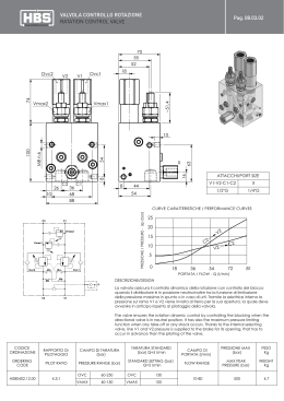
2/ NV
COMPONENTI MODULARI SERIE “N” e “V”
MODULAR MANIFOLD BLOCKS “N” & “V” SERIES
Rev. 05/06
Componenti s.r.l.
COMPONENTI MODULARI SERIE “N” e SERIE “V”
MODULAR MANIFOLD BLOCKS “N” & “V” SERIES
Con i cataloghi COMPONENTI MODULARI SERIE "N" e COMPONENTI MODULARI SERIE "V" la OIL SISTEM componenti presenta
la sua vastissima gamma di elementi modulari per la realizzazione semplice ed economica di qualsiasi tipo di circuito.
Per ovvie ragioni di spazio non e'stato possibile rappresentare tutta la produzione di elementi modulari quindi per applicazioni non ancora
codificate rivolgersi al nostro Ufficio Commerciale.
COLLETTORI:
Vengono realizzati in alluminio estruso ad alta resistenza per impieghi oleodinamici. A richiesta collettori in
acciaio.
VALVOLE A CARTUCCIA: Le valvole vengono realizzate in acciaio di alta qualità con parti in movimento indurite e rettificate o lappate.
Le parti esterne vengono protette mediante fosfatazione o zincatura.
ATTACCHI:
gli attacchi filettati sono del tipo GAS (BSPP)
GUARNIZIONI:
Normalmente realizzate in BUNA N per temperature da -20 a +90° centigradi.
OLIO IDRAULICO:
Si raccomanda l'impiego di oli a base minerale, come il tipo HLP secondo DIN 51524. Tutti i collaudi funzionali
e le tarature vengono eseguiti con un olio avente viscosità di 46 cST alla temperatura di 40° centigradi.
FILTRAGGIO:
Trattandosi di valvole con accoppiamenti di precisione si raccomanda l'uso di un filtraggio max di 25 micron.
MARCATURA VALVOLE: Ogni corpo valvola reca impresse le seguenti marcature :
- Denominazione ( es. N03 V02 V07 )
- Identificazione del costruttore (OIL SISTEM)
- Identificazione degli attacchi (esempio A-B-C)
OIL SISTEM Componenti introduces our Modular Manifold Block Range “N” & “V” series to be directly mounted on to our power packs.
Thanks to the huge range of these blocks it is very easy to design a hydraulic circuit that you may need. You will find here the most
popular blocks that we use on daily basis, but upon request you can have special ones produced. Ask our Sales Departement for further
details.
MANIFOLD:
Made of alluminum for high pressure hydrailics.
CARTRIDGE VALVES:
The valve are made of high quality cast-iron, with internal spools threaded, lapped and rectified.
PORTS:
The spools are all threaded BSPP.
GASKETS:
The gaskets are made of BUNA N and are able to work between –20/+90°C.
HYDRAULIC OIL:
We suggest mineral hydraulic oil as standard (HLP type DIN 51524).
All the tests and the setting of the valves are made with oil having 46cst viscosity at a temperature of 40°C
FILTER:
We suggest to use a 25 micron filter.
PRINTING:
All our Blocks are printed with:
- Denomination (N03 – V02 – V07 etc…)
- Name of manufacturer (OIL SISTEM)
- Ports denomination (A – B – P – T – etc…)
- Date of production.
Specifiche, caratteristiche, dimensioni, descrizioni contenute nel presente catalogo erano al meglio della conoscenza al momento della
stampa.
La OIL SISTEM si riserva il diritto di cessare la produzione di qualsiasi modello o di variarne specifiche o disegni in ogni momento senza
preavviso e senza incorrere in obblighi.
Il presente catalogo annulla e sostituisce i precedenti.
Specifications, characteristics, dimensions, and all the descriptions held in this catalogue were done according to the acknoledgments
when this catalogue has been printed.
Oil Sistem reserves the right to cease the production of any model or to modify any specification or drawing at any time and without preadvise, without incurring any obligations.
This present catalogue supercedes any previuos ones.
2
Componenti s.r.l.
MODULO DI BASE CON VALVOLA CONTROLLO PRESSIONE PER MONTAGGIO ELEMENTI MODULARI
Base block complete with relief valve for assembling of modular elements
G03
DENOMINAZIONE VALVOLA
Valve denomination
27
Base per montaggio di blocchi del nostro sistema modulare che consente
un facile montaggio.Valvola di massima VM30
- A richiesta è possibile fornire la base con valvola di ritegno incorporata
(portata massima 15 l/min).
- Filtraggio consigliato: 50 micron o inferiore.
9.5
34
5
9.5
P
76
48 max
Base block ables to accept our modular manifold block for easy installation.
The block comes complete with “VM30” relief valve cartridge.
- Upon request it is possible to supply the base with a 15 lt/min flow relief
valve.
- Suggested Filtration: 50 micron nominal or better
80
T
61
52
ø6.
18.5
G3.852.03.X.Y.Z.
9.5
29
8
CODICE ORDINAZIONE
Ordering code
10
95.5
26.5
34
P
P
T
P
T
40
15
T
Faccia appoggio blocchi modulari
PRESSURE - PRESSIONE -
P (bar)
400
350
300
300
250
X
200
200
Regolazioni
Adjustments
150
100
100
3
4
0
A
0
Valore minimo di taratura
2
125
50
Lowest adjustable setting
vite esterna
esagono incassato
leakproof hex.
socket screw
50
100
40
75
30
50
20
25
10
0
0
5
10
15
20
25
30
0
5
10
15
20
25
30
FLOW - PORTATA - Q (l/min)
Molle / Springs
Z
2
Y
Campo taratura (bar)
Adj. press. range (bar)
Taratura standard
(bar) ( Q=5 L/min)
Std. setting bar
(made at 5 l/min)
30 - 100
100
Blu
Blue
Verde
Green
Giallo
Yellow
3
50 - 210
200
4
100 - 350
350
pressione di lavoro max.
max working pressure
300 bar
Codice ordinazione
Ordering code
Attacchi / Port Size
P-T
Colore
Colour
2
3/8"BSPP
portata max.
max flow
peso
weight
30 l/min
kg. 0.90
3
Componenti s.r.l.
MODULO DISTANZIATORE
Space modular block
N09 (H = 18)
DENOMINAZIONE VALVOLA
Valve denomination
CODICE ORDINAZIONE
Ordering code
G3.860.10.000
N01 (H = 39)
G3.860.01.000
N02 (H = 69)
G3.860.38.000
50
ø8
.5
Blocchi modulari utili per distanziare i blocchi sovrapposti da ingombri di
flange, motori od altro che ne impediscano il montaggio.
- Ogni blocco viene fornito completo dei 2 OR 2056.
These modular blocks have been designed to have the ability to be
assembled as a stack to allow clearence between flanges and motors of
different sizes and types.
- Each block includes 2 OR 2056 gaskets.
P
14
T
8
18.5
34
27
8
H
95.5
P
Motore Grandezza IEC71 Trascinamento F68 - Motor IEC71 frame Coupling “F68”
T
Motore Grandezza IEC90 Trascinamento F16 - Motor IEC80 frame Coupling “F14”
N03
N03
N09
N09
Motore Grandezza IEC80 Trascinamento F14 - Motor IEC90 frame Coupling “F16”
Motore Grandezza IEC100 Trascinamento F18 - Motor IEC100 frame Coupling “F18”
N03
N03
N09
N01
N09
N01
Motore Grandezza IEC112 Trascinamento F18 - Motor IEC112 frame Coupling “F18”
N03
N01
N01
pressione di lavoro max.
max working pressure
300 bar
portata max.
max flow
40 l/min
4
Componenti s.r.l.
MODULO DISTANZIATORE
Space modular block
N92
N92
DENOMINAZIONE VALVOLA
Valve denomination
CODICE ORDINAZIONE
Ordering code
G3.860.91.000
N201
G3.862.01.000
30
ø8
.5
Blocchi modulari utili per distanziare i blocchi sovrapposti da ingombri di
flange, motori od altro che ne impediscano il montaggio.
- Ogni blocco viene fornito completo dei 2 OR 2056.
These modular blocks have been designed to have the ability to be
assembled as a stack to allow clearence between flanges and motors of
different sizes and types.
- Each block includes 2 OR 2056 gaskets.
P
14
T
8
N92
18.5
34
27
8
25
95.5
T
P
T
.5
M
ø8
40
P
P
14
T
8
N201
18.5
34
27
8
95.5
27
P1PM
M = 1/4"BSPP
Motore grandezza IEC132 Trascinamento F67 - Motor IEC132 frame coupling F67
Motore grandezza IEC90 Trascinamento TR08 - Motor IEC90 frame coupling TR08
pressione di lavoro max.
max working pressure
300 bar
portata max.
max flow
40 l/min
5
Componenti s.r.l.
MODULO PER ROTAZIONE FIGURA DI 90° SULLO STESSO PIANO
90° rotation modular block
N33
CODICE ORDINAZIONE
Ordering code
14
DENOMINAZIONE VALVOLA
Valve denomination
P
G3.860.32.000
Blocco modulare che esegue la rotazione di 90° della configurazione standard
mantenendola sul medesimo piano e consentendo quindi un diverso
orientamento dei moduli soprastanti.
- Ogni blocco viene fornito completo dei 2 OR 2056.
T
A modular block that is able to have a 90° rotation from our standard OIL
SISTEM configuration, but keeping the block on the same surface allowing
a different position of any other modular block.
- Each block includes 2 OR 2056 gaskets.
34
T1
.5
ø8
95.0
18.5
8
M8
P1
27
P1
T1
79.5
12
P
100
ESEMPIO DI APPLICAZIONE
APPLICATION EXAMPLE
N33
pressione di lavoro max.
max working pressure
300 bar
portata max.
max flow
35 l/min
6
T
Componenti s.r.l.
MODULO PER ROTAZIONE FIGURA DI 90° MONTAGGIO BLOCCHI IN ORIZZONTALE LATO MOTORE
90° modular block allowing horizontal mounting (motor side)
N15 (H = 90)
DENOMINAZIONE VALVOLA
Valve denomination
CODICE ORDINAZIONE
Ordering code
G3.860.14.000
N51 (H = 60)
G3.860.50.000
8
P1
T1
A modular block that is able to turn the standard assembling of 90°, in
order to place other manifold blocks over the motor.
- The “N15” block has a 1/4” BSPP port for Pressure Gauge
- Each block includes 2 OR 2056 gaskets.
55
(25)
h
M
Blocco che esegue la rotazione di 90° della figura standard consentendo
il montaggio degli altri moduli con sviluppo sopra il motore della centralina.
- Il blocco N15 è provvisto di un foro da 1/4"BSPP per manometro.
- Ogni blocco viene fornito com pleto dei 2 OR 2056.
17
M
T
8
18.5
34
27
M (1/4"BSP)
8
Solo N51
Only N51
40
ø8.5
23
N51
N15
P
P2
T1
T1
P1
P1
T2
9
T2
P2
P
95.5
Motore Grandezza IEC71 Trascinamento F68 - Motor IEC71 frame Coupling “F68”
N03
T
P
T
Motore Grandezza IEC90 Trascinamento F16 - Motor IEC90 frame Coupling “F16”
N51
N03
Motore Grandezza IEC80 Trascinamento F14 - Motor IEC80 frame Coupling “F14”
N15
Motore Grandezza IEC100 Trascinamento F18 - Motor IEC100 frame Coupling “F18”
N51
N03
N03
N15
Motore Grandezza IEC112 Trascinamento F18 - Motor IEC112 frame Coupling “F18”
N03
pressione di lavoro max.
max working pressure
300 bar
N15
portata max.
max flow
peso
weight
35 l/min
N51 = kg. 0.63 • N15 = kg. 0.85
7
Componenti s.r.l.
MODULO PER ROTAZIONE FIGURA DI 90° MONTAGGIO BLOCCHI IN ORIZZONTALE LATO SERBATOIO
90° modular block allowing horizontal mounting (tank side)
N26 (H = 60)
DENOMINAZIONE VALVOLA
Valve denomination
CODICE ORDINAZIONE
Ordering code
N76 (H = 90)
G3.860.25.000
G3.860.75.000
Blocco che esegue la rotazione di 90° della figura standard consentendo
il montaggio degli altri moduli con sviluppo sopra il serbatoio della centralina.
- Il blocco è provvisto di un fo ro da 1/4"BSPP per manometro.
- Ogni blocco viene fornito completo dei 2 OR 2056.
T1
M
25
(55)
h
P1
P
8
27
A modular block that is able to turn the standard assembling of 90° , in
order to place other blocks over the tank.
- The blocks have a 1/4” BSPP port for Pressure Gauge.
- Each block includes 2 OR 2056 gaskets.
8
T
34
18.5
8
M (1/4"BSPP)
ø8
17
M
.5
40
P1
T1
60.5
95.5
P
Serbatoio diametro ø123 - Tank Diameter “123”
N26
pressione di lavoro max.
max working pressure
300 bar
T
Serbatoio diametro ø190 - Tank Diameter “190“
N76
N03
N03
portata max.
max flow
peso
weight
35 l/min
N26 = kg. 0.56 • N76 = kg. 0.78
8
Componenti s.r.l.
MODULI PER CENTRALINA CON USCITE FILETTATE
Modular blocks with threaded ports
N96
DENOMINAZIONE VALVOLA
Valve denomination
CODICE ORDINAZIONE
Ordering code
G3.860.95.0.0.0.
N191
G3.861.91.0.0.0.
N163
G3.861.63.0.0.0.
Blocco per trasformare le uscite P e T dei nostri collettori da centralina in
attacchi filettati.
- Ogni blocco viene fornito completo dei 2 OR 2056.
32.5
P
T
30
These modular blocks allow a female thread to be taken directly from the
power pack manifold to go directly to external valves.
- Each block includes 2 OR 2056 gaskets.
N96
P
T
P
T
30
95.5
P-T = 3/8"BSPP
M 1/4"BSPP
40
P
N191
P
95.5
30
M
P
T
P = 3/8"BSPP
35.5
T
40
P
N163
P
T
P
T
30
95.5
P-T = 1/2"BSPP
pressione di lavoro max.
max working pressure
300 bar
portata max.
max flow
35 l/min
9
Componenti s.r.l.
MODULO INTERPOSIZIONE CON USCITA “P”
Modular spacer block with extra “P” port
N46
DENOMINAZIONE VALVOLA
Valve denomination
CODICE ORDINAZIONE
Ordering code
G3.860.45.0.0.0.
Blocco interposizione con uscita 1/4" BSPP.
- Ogni blocco viene fornito completo dei 2 OR 2056.
A modular block with an extra 1/4” BSPP port
- Each block includes 2 OR 2056 gaskets.
35
50
P1
14
P
T
P1
8
18.5
34
95.5
27
8
15
30
Attacchi / Port Size
P1
T
1/4" BSPP
P
pressione di lavoro max.
max working pressure
300 bar
portata max.
max flow
peso
weight
20 l/min
kg. 0.14
MODULO DISTANZIALE CON 2 ATTACCHI PRESSOSTATO DA 1/8"BSPT E 2 ATTACCHI MANOMETRO DA 1/4"BSPP
Modular spacer block with two 1/8” BSPP ports for Pressure Switches and two 1/4” BSPP ports for Pressure Gauges
N128
DENOMINAZIONE VALVOLA
Valve denomination
CODICE ORDINAZIONE
Ordering code
G3.861.28.0.0.0.
Blocco distanziale con predisposizione per il montaggio di manometro e
pressostati.
- Ogni blocco viene fornito completo dei 2 OR 2056.
30
50
Modular spacer block able to hold two pressure gauges and two pressure
switches.
14
P
Pressostato Pr
Pressostato Pr
8
18.5
34
95.5
T
Pr
27
Manometro M
Manometro M
P
M
Pr
M
Attacchi / Port Size
17.5
35
8
P-T
20
pressione di lavoro max.
max working pressure
300 bar
1/4" BSPP
35
portata max.
max flow
peso
weight
35 l/min
kg. 0.41
10
T
Componenti s.r.l.
MODULO CON VALVOLA DI RITEGNO SU “P”
Modular spacer block with a check valve on the “P” line
N57
DENOMINAZIONE VALVOLA
Valve denomination
CODICE ORDINAZIONE
Ordering code
G3.860.56.0.0.0.
T
Modular spacer block with a check valve on the “P” line.
- Each block includes 2 OR 2056 gaskets.
P
14
50
55.5
Modulo con ritegno a sfera sulla condotta di mandata P.
- Ogni blocco viene fornito completo dei 2 OR 2056.
8
18.5
34
27
8
95.5
P1
T
P
T
25
P1
PRESSURE - PRESSIONE -
P (bar)
12
9
6
P
P1
3
0
4
8
12
16
20
FLOW - PORTATA - Q (l/min)
Attacchi / Port Size
Molle / Springs
P1 - T
Inizio apertura (bar)
Cracking pressure (bar)
Ø 11.5
0.5
pressione di lavoro max.
max working pressure
300 bar
portata max.
max flow
peso
weight
20 l/min
kg. 0.32
11
Componenti s.r.l.
MODULO REGOLATORE DI FLUSSO A 3 VIE (compensazione barica)
Modular block with 3 way flow divider (baric compensation)
N31
CODICE ORDINAZIONE
Ordering code
DENOMINAZIONE VALVOLA
Valve denomination
14
40.5
60
Modulo che consente di mantenere costante la portata al valore
stabilito indipendentemente dalla pressione richiesta dall'attuatore
o dalla portata in ingresso.
La portata eccedente viene scaricata in serbatoio ad una pressione
di pochi bar superiore a quella di lavoro.
- Filtraggio consigliato: 25 micron o inferiore.
- Ogni blocco viene fornito completo dei 2 OR 2056.
8
18.5
34
27
P1
T
P
44 max
P1
T1
P
T
ø37.5
28.5
45
T1
Modular block that allows you to keep a preset flow indipendently
by the working pressure or the total flow.
The exceeding flow returns to tank at a pressure little higher than
the working pressure.
- Suggested Filtration 25 micron nominal or better.
- Each block includes 2 OR 2056 gaskets.
8
95.5
X
FLOW - PORTATA - Q (l/min)
G3.860.30.X.1.0.
Regolazioni
Adjustments
60
50
40
30
B
volantino e controvolantino
handknob and locknut
20
10
Attacchi / Port Size
0
42
84
126
PRESSURE - PRESSIONE -
pressione di lavoro max.
max working pressure
210 bar
210
168
P (bar)
P1 - T1
Ø 11.5
portata max.
max flow
peso
weight
25 l/min
kg. 0.85
12
Componenti s.r.l.
MODULO CON REGOLATORE DI FLUSSO 3 VIE 2 UTILIZZI
Modular block with 3 way flow devider and 2 ports
N41
DENOMINAZIONE VALVOLA
Valve denomination
CODICE ORDINAZIONE
Ordering code
G3.860.40.X.0.Z.
70
Modulo con valvola regolatrice di flusso a 3 vie VRFP che consente
di mantenere costante la portata prioritaria P1 indipendentemente
dalla portata in eccesso P2 e dalla pressione di lavoro.
- Filtraggio consigliato: 25 micron o inferiore.
- Ogni blocco viene fornito completo dei 2 OR 2056
.5
T
Modular block with “VRFP” 3 way flow devider that allows you to
keep the preset flow on “P1” indipendently by the exceeding flow
of the “P2” and the working pressure.
- Suggested Filtration 25 micron nominal or better
- Each block includes 2 OR 2056 gaskets.
P
14
37
ø8
8
18.5
34
27
8
95.5
T1
65 max
P1
P1
T2
T2
14
33
50
P2
T1
P2
8
27
34
18.5
8
P
PRIORITY PRESSURE (bar)
REG.FLOW QP1 (l/min)
FLUSSO REGOL. QP1 (l/min)
210
140
70
0
70
140
210
PRESSIONE IN P1 (bar)
140
70
0
70
140
48
36
210
24
Z=4
Z=3
X
Regolazioni
Adjustments
18
24
12
12
6
0-16
12
T
A
vite esterna
esagono incassato
leakproof hex.
socket screw
B
volantino e dado
handknob and locknut
8-0
Z=2
Z=1
6
8
4
4
2
0
0
*
*
**
*
**
*
( ) I campi di sinistra dei 4 diagrammi, indicati con , si riferiscono a quando la pressione in “P2” è superiore
a quella in “P1”
*
The left end field of the above shown diagrams,marked with , refers to by-pass pressure “P2” exceeding
priority pressure “P1”
di destra dei 4 diagrammi, indicati con **, si riferiscono a quando la pressione in “P1” è superiore
**) Iacampi
quella in “P2”
(
The right end field of the above shown diagrams, marked with
by-pass pressure “P2”
pressione di lavoro max.
max working pressure
210 bar
**, refers to priority pressure “P1” exceeding
Z
Campo di regolazione portata
Regulated flow range
1
2 - 6 l/min
2
5 - 10 l/min
3
10 - 18 l/min
4
20 - 35 l/min
QP = portata max in entrata P = 40 l/min
QP1 = portata max in uscita prioritaria P1 = 35 l/min
QP = max. admitted inlet flow P port = 40 l/min
QP1 = max. delivery in priority flow P1 port = 35 l/min
13
peso
weight
kg. 1.08
Componenti s.r.l.
MODULO DIVISORE DI FLUSSO A TARATURA FISSA
Modular block with fixed setting flow divider
N29
DENOMINAZIONE VALVOLA
Valve denomination
CODICE ORDINAZIONE
Ordering code
G3.860.28.X.Y.Z.
N30
G3.860.29.X.Y.Z.
80
50
A
A T
P
B
A
B
T1
P1
A
N29
T
112
P
P1
B
Modulo divisore di flusso che consente
di dividere il flusso in entrata “P” in rapporti
definiti indipendentemente dal carico sugli
utilizzi.
Per un buon funzionamento delle valvole
(errore inferiore a ±3%) scegliere il divisore
in base ai dati della tabella “Z” indicante
la portata minima e massima accettabile
in entrata.
- Filtraggio consigliato: 25 micron o
inferiore
- Ogni blocco viene fornito completo dei
2 OR 2056
T1
T
A modular block with fixed flow divider
that allows you to split 50/50 the flow in
the pressure line, indipendently by the
weigth on the ports.
In order to have a good working effort
(tollerance 3%) please refer to the diagram
here below (Z) to chose the exact entering
flow.
- Suggested Filtration 50 micron nominal
or better
- Each block includes 2 OR 2056 gaskets
P
7
B
80
50
T2
P2
P1
T1
P2
112
N30
P1
T1
T2
P
7
T
PRESSURE - PRESSIONE - P (bar)
1
2
3
Z
4
12
9
6
0
50% - 50%
12
18
24
30
36
40
FLOW - PORTATA - Q (l/min)
pressione di lavoro max.
max working pressure
210 bar
Flow range
(max admitted slippage ±3%)
2.8 - 5.8 l/min
2
6.5 - 11 l/min
3
13 - 22 l/min
4
25 - 38 l/min
Y
6
(max errore ±3%)
1
3
0
Rapporto di divisione
Flow division ratio
Campo di portata
18
15
X
1
Attacchi / Port Size
A-B-P1-T1 (N29)
P1-T1-P2-T2 (N30)
1/4"BSPP
1/4"BSPP
portata max.
max flow
peso
weight
vedi tabella / refer to the diagram
kg. 1.30
14
Componenti s.r.l.
MODULO CON VALVOLA RIDUTTRICE DI PRESSIONE
Modular block with pressure reducing valve
N73
DENOMINAZIONE VALVOLA
Valve denomination
CODICE ORDINAZIONE
Ordering code
Modulo con valvola riduttrice VRP 50 che mantiene la pressione in un circuito
secondario inferiore a quella del circuito primario.
Il pilotaggio interno consente di mantenere la pressione regolata praticamente
costante entro un ampio intervallo di portata.
- Filtraggio consigliato: 25 micron o inferiore.
- Trafilamento max da P a T: 0.30 l/1' alla massima pressione.
ch.14
ch.14
P
A modular block with “VRP50” pressure reducing valve that allows you to keep
the pressure on a seconary cuircuit lower than the pressure on the primary
circuit.
The inside piloting allows you to keep a costant preset pressure within quite
a big flow range.
- Suggested Filtration 50 micron nominal or better
- Each block includes 2 OR 2056 gaskets.
- Max leaking from P to T: 0.30 lt/min at the max pressure
14
40
60
ch.27
Vite di regolazione interna ch.5
T
8
18.5
34
27
8
95.5
50
T1
66
P1
P1
T1
P2
T2
14
32
P2
G3.860.72.X.0.Z.
T2
8
27
34
18.5 8
P
T
PRESSURE - PRESSIONE-
P (bar)
210
X
175
140
A
105
Regolazioni
Adjustments
vite interna
esagono incassato
leakproof inner hex.
socket screw
70
35
15
0
30
45
FLOW - PORTATA - Q (l/min)
Attacchi / Port Size
Molle / Springs
Z
3
Campo taratura (bar)
Adj. press. range (bar)
Taratura standard
(bar) ( Q=5 L/min)
Std. setting bar
(made at 5 l/min)
20 - 210
70
Codice ordinazione
Ordering code
Colore
Colour
Verde
Green
pressione di lavoro max.
max working pressure
portata max.
max flow
in entrata / inlet = 350 bar
regolata / regulated = 210 bar
40 l/min
15
P1 - T1
P2 - T2
1/4"BSPP
1/4"BSPP
Componenti s.r.l.
MODULO CON VALVOLA DI MESSA A SCARICO E RITEGNO ANTISVUOTAMENTO
Modular block with P.O. unloading valve and anti-drain check valve
N72
CODICE ORDINAZIONE
Ordering code
DENOMINAZIONE VALVOLA
Valve denomination
N273
G3.860.71.X00
.5
8
N72
18.5
27
34
4.5
ø8
14
60
13.860.00.027
8
95.5
9
P1
This manifold block allows the oil to return to tank from “P1”
when the “P” line is without pressure. On the return to tank
line from “P1” there is placed a check valve which is needed
to avoid a complete drain of the circuit (X=0). This means that
the flow goes back to tank when the pressure in the “P” line
get lower than the value of the pressure on the “P” line till the
two pressures are the same.
- Each block includes 2 OR 2056 gaskets.
40
24.5
T1
Questa valvola svolge la funzione di mettere a scarico il ramo
di alimentazione generale “P1” quando viene a mancare il
flusso della pompa in “P”.
Sul condotto di scarico e'inserito un ritegno che serve per
impedire lo svuotamento del circuito (X=0).
In pratica il flusso viene dirottato in scarico quando la pressione
in “P” scende ad un valore inferiore a quello del ramo “P1”
fino ad assumere di nuovo lo stesso valore.
- Filtraggio consigliato: 50 micron o inferiore
Schema
Symbol
X
T
P
P1
T1
0
60
1.8 bar
14
.5
8
18.5
8
T1
P1
T
P
T1
B
P
T
40
24.5
N273
27
34
95.5
9
T
P1
4.5
ø8
P
Attacchi / Port Size
P1 - T1
N273 è disponibile soltanto con schema B.
N273 is only available with scheme B.
pressione di lavoro max.
max working pressure
300 bar
portata max.
max flow
schema X=0
schema X=B
16
20 l/min
40 l/min
N72
P1 = 1/4” BSPP, T1 = 1/4" BSPP
N273
P1 = 3/8” BSPP, T1 = 1/4" BSPP
peso
weight
kg. 0.90
Componenti s.r.l.
MODULO PER FILTRO IN PRESSIONE
Modular block with filter on pressure line
N39
CODICE ORDINAZIONE
Ordering code
DENOMINAZIONE VALVOLA
Valve denomination
G3.860.38.0.Y.0.
Blocco con filtro sinterizzato sul condotto di mandata indicato per
circuiti con valvole sensibili alle impurità.
- Ogni blocco viene fornito completo dei 2 OR 2056.
ch.34
60
A modular block with a filter on the pressure line. This is
recommended for applications where valve may be subjected to
contamination.
- Each block includes 2 OR 2056 gaskets.
T
8
18.5
P
34
27
8
95.5
P
50
102.5
pressione di lavoro max.
max working pressure
250 bar
T
Y
Filtraggio
Filtration
1
25 micron
2
60 micron
portata max.
max flow
peso
weight
10 l/min
kg. 0.75
MODULO PER FILTRO IN SCARICO
Modular block with filter on the return line
14
18.5
P
34
100
27
G3.861.16.0.1.0.
Modulo con filtro in scarico da montarsi in linea,
particolarmente indicato in circuiti ove esistano valvole
molto sensibili alle impurita.
Caratteristiche tecniche filtro:
- Pressione di lavoro max = 6 bar
- Pressione di scoppio = 20 bar
- Valvola di by-pass tarata 1 bar
- Ogni blocco viene fornito completo dei 2 OR 2056.
ø48.5
T
8
CODICE ORDINAZIONE
Ordering code
DENOMINAZIONE VALVOLA
Valve denomination
60
N116
A modular block for the return line. This is recommended
for applications where valves may be subjected to
contamination.
- Each block includes 2 OR 2056 gaskets.
- By-pass valve set @ a pressure of 1 bar
12.5
110
ch.13
P
1 bar
60
FILTRAGGIO
FILTRATION
T
20 micron
P
pressione di lavoro max.
max working pressure
6 bar
T
portata max.
max flow
peso
weight
20 l/min
kg. 1.16
17
Componenti s.r.l.
MODULO DI CONVERSIONE PER MONTAGGIO VALVOLE IN CONFIGURAZIONE CETOP 2 (luce ø5)
Modular block able to accept CETOP 2 configuration valves.
in parallelo
N95 ( coll.
parallel circuit )
coll. in serie
N120 ( series
circuit )
DENOMINAZIONE VALVOLA
Valve denomination
CODICE ORDINAZIONE
Ordering code
G3.860.94.0.1.0.
G3.861.20.0.1.0.
T
A modular block that is able to accept CETOP 2 electrovalves for
parallel or series circuits.
- Each block includes 2 OR 2056 gaskets.
P
14
31
45
Blocchi modulari per montaggio di valvole con configurazione
CETOP 2 (luce ø5) per circuiti in serie e in parallelo.
-Ogni blocco viene fornito completo dei 2 OR 2056.
ø8
8
18.5
34
27
.5
N95
P1
8
T1
B
T
P
A
P
B
T1
B
B
T
P
A
A
T
P
T
B
A
P1
A
P1
P
45
T1
B
95.5
A
N120
T
Attacchi / Port Size
T1
43.5
pressione di lavoro max.
max working pressure
300 bar
A-B
P1-T1
1/4"BSPP
1/4"BSPP
portata max.
max flow
peso
weight
20 l/min
kg. 0.40
MODULO DI CONVERSIONE PER MONTAGGIO VALVOLE IN CONFIGURAZIONE CETOP 2 (luce ø5)
Modular block able to accept CETOP 2 configuration valves.
N210
CODICE ORDINAZIONE
Ordering code
DENOMINAZIONE VALVOLA
Valve denomination
G3.862.10.0.1.0.
45
Blocco modulare per montaggio di valvole CETOP 2 (luce ø5) per
circuiti in parallelo con attacchi posteriori.
-Ogni blocco viene fornito completo dei 2 OR 2056.
T
A modular block that is able to accept CETOP 2 electrovalves for
a parallel circuit with ports on the under side of the block.
Each block includes 2 OR 2056 gaskets.
14
P
ø8
A
8
18.5
.5
B
34
27
P1
8
95.5
T1
B
T
P
A
A
P1
P
P
45
A
T
300 bar
T
B
T1
Attacchi / Port Size
43.5
pressione di lavoro max.
max working pressure
T1
B
A-B
P1-T1
1/4"BSPP
1/4"BSPP
portata max.
max flow
peso
weight
20 l/min
kg. 0.40
18
Componenti s.r.l.
MODULO PER ELETTROVALVOLA CETOP 2 (luce ø5) CON VALVOLE DI RITEGNO PILOTATE A SFERA
Modular block with P.O. check valves able to accept CETOP 2 configuration valves
in parallelo
N211 ( coll.
parallel circuit )
in parallelo
N212 ( coll.
parallel circuit )
DENOMINAZIONE VALVOLA
Valve denomination
CODICE ORDINAZIONE
Ordering code
G3.862.11.X.Y.0
G3.862.12.X.Y.0
in parallelo
N213 ( coll.
parallel circuit )
G3.862.13.X.Y.0
P
45
A
A
B
B
T
Modulo per elettrovalvola CETOP 2 con valvole unidirezionali a sfera a sbloccaggio
oleodinamico.
- Filtraggio consigliat: 50 micron o inferiore
- Trafilamento: nullo
A selection of modular blocks fitted with P.O. check valves able to accept CETOP
2 (2143) electrovalves.
- Each block includes 4 OR 108 gaskets.
- Leakage free
- Suggested filtration: 50 micron nominal or better
T
53
106
N211
151
1/4"BSPP
P1
T1
A
14
29.5
45
P1
N212
T1
B
Attacchi / Port Size
Y
1
A-B
P1-T1
1/4"BSPP
1/4"BSPP
T
P
P
B
B
P
T
Rapporto di pilotaggio
Pilot ratio
A
T
B
P
P1
T1
A
A
P1
N213
T1
A
A
T
P
B
B
P
T
T
X
Guarnizione sul pistone di pilotaggio
O-ring on pilot piston
A
Senza guarnizione / no O-ring
B
Con guarnizione / with O-ring
4:1
pressione di lavoro max.
max working pressure
portata max.
max flow
250 bar
16 l/min
MODULO DI CONVERSIONE PER MONTAGGIO VALVOLE IN CONFIGURAZIONE CETOP 2 (luce ø5)
Modular block able to accept CETOP 2 configuration valves
N155
CODICE ORDINAZIONE
Ordering code
45
DENOMINAZIONE VALVOLA
Valve denomination
Blocchi modulari per montaggio di valvole con configurazione CETOP 2
(luce ø5) per circuiti in parallelo.
- Ogni blocco viene fornito completo dei 2 OR 2056.
P
30
T
14
ø8
8
18.5
34
27
G3.861.55.0.1.0.
A modular block that is able to accept CETOP 2 electrovalves for parallel circuits.
- Each block includes 2 OR 2056 gaskets.
.5
8
95.5
T1
P1
P1
T1
B
A
B
P
A
P
43.5
pressione di lavoro max.
max working pressure
300 bar
B
T
P
A
B
A
45
T
portata max.
max flow
20 l/min
19
T
Attacchi / Port Size
A-B
P1-T1
1/4"BSPP
1/4"BSPP
MODULO PER ELETTROVALVOLA CETOP 2 (luce
CON VALVOLE DI RITEGNO PILOTATE AD
OTTURATORE CONICO GUIDATO
5)
DENOMINAZIONE VALVOLA Valve denomination
N224
N225
N226
45
Codice ordinazione
Ordering code
G3.862.24.X.Y.Z.
G3.862.25.X.Y.Z.
G3.862.26.X.Y.Z.
(coll.in parallelo)
(coll.in parallelo)
(coll.in parallelo)
Modulo per elettrovalvola CETOP 2 con valvole unidirezionali a sbloccaggio oleodinamico.
- Filtraggio consigliato: 50 micron o inferiore
- Trafilamento : nullo
- Possibilita' di montare OR sul pistone di pilotaggio
P
A
-.--.--
PAGINA
B
T1
47.75
33.5
95.5
33.5
162.5
14
Rapporto di pilotaggio
Pilot ratio
P1
4 : 1
50
34
T1
N224
P1
N225
A
P
P
B
T
P
P
B
B
T
A
B
P
T
T
15
12
- PRESSIONE -
P (bar)
T
T1
A
A
T
B
P
N226
P1
T1
A
A
B
PRESSURE
P1
T1
X
9
6
A
GUARNIZIONE SUL PISTONE
DI PILOTAGGIO
O-RING ON PILOT PISTON
A
Senza guarnizione
no O-Ring
B
Con guarnizione
with O-Ring
3
B
0
5
10
15
20
FLOW - PORTATA - Q (l/min)
A = Caduta di pressione in portata libera
B = Caduta di pressione con apertura pilotata
Y
0
MOLLE / SPRINGS
Inizio apertura (bar) Cracking pressure (bar)
Z
2
pressione di lavoro max.
max working pressure
300 bar
portata max.
flow max
20
l/min
ATTACCHI / PORT SIZE
A-B
P1-T1
1
1/4"BSPP
1/4"BSPP
2
3/8"BSPP
1/4"BSPP
peso
weight
Componenti s.r.l.
MODULO DI CONVERSIONE PER MONTAGGIO VALVOLE IN CONFIGURAZIONE CETOP 2143 (luce ø6)
Modular block able to accept CETOP 3 (2143) configuration valves
in parallelo
N03 ( coll.
parallel circuit )
coll. in serie
N11 ( series
circuit )
DENOMINAZIONE VALVOLA
Valve denomination
CODICE ORDINAZIONE
Ordering code
G3.860.02.0.Y.0.
G3.860.09.0.Y.0.
50
Blocchi modulari per montaggio di valvole con configurazione CETOP 2143
(luce ø6) per circuiti in serie e in parallelo.
-Ogni blocco viene fornito completo dei 2 OR 2056.
35
T
Modular blocks able to accept CETOP 3 (2143) electrovalves for parallel or
series circuits
Each block includes 2 OR 2056 gaskets.
P
14
ø8
8
18.5
34
27
.5
N03
P1
8
T1
P1
P
T1
B
B
T
P
A
A
T
P
T
B
A
P1
B
T
P
A
A
T
50
T1
B
95.5
A
N11
B
Attacchi / Port Size
Y
P
43.5
pressione di lavoro max.
max working pressure
A-B
P1-T1
1
1/4" BSPP
1/4" BSPP
2
3/8" BSPP
1/4" BSPP
portata max.
max flow
peso
weight
40 l/min
kg. 0.56
300 bar
MODULO DI CONVERSIONE PER MONTAGGIO VALVOLE IN CONFIGURAZIONE CETOP 2143 (luce ø6)
Modular block able to accept CETOP 3 (2143) configuration valves
CODICE ORDINAZIONE
Ordering code
DENOMINAZIONE VALVOLA
Valve denomination
G3.860.84.0.Y.0.
Blocco modulare per montaggio di valvole CETOP 2143 (luce ø6) per circuiti
in parallelo con attacchi posteriori.
- Ogni blocco viene fornito completo dei 2 OR 2056.
T
P
(25 Y=2)
50 (60 per Y=2)
20
in parallelo
N85 ( coll.
parallel circuit )
ø8
P1
A
8
.5
A modular block that is able to accept CETOP 3 (2143) electrovalves for a
parallel circuit with ports on the under side of the block.
- Each block includes 2 OR 2056 gaskets.
18.5
B
34
27
T1
B
B
T
P
A
8
95.5
A
T1
P1
P
T
T
50
A
Attacchi / Port Size
B
Y
A-B
P1-T1
1
1/4" BSPP
1/4" BSPP
2
3/8" BSPP
1/4" BSPP
P
48
pressione di lavoro max.
max working pressure
300 bar
portata max.
max flow
peso
weight
40 l/min
kg. 0.57
21
Componenti s.r.l.
MODULO DI CONVERSIONE PER MONTAGGIO DI UNA VALVOLA IN CONFIGURAZIONE CETOP 2143 (luce ø6)
Modular block able to accept CETOP 3 (2143) configuration valves
N16
CODICE ORDINAZIONE
Ordering code
DENOMINAZIONE VALVOLA
Valve denomination
G3.860.15.0.Y.0.
Blocco modulare per il montaggio di un pacco di valvole con
configurazione CETOP 2143 (luce ø6) con sviluppo in altezza.
- Ogni blocco viene fornito completo dei 2 OR 2056.
A modular block that is able to accept CETOP 3 (2143)
electrovalves for end mounting.
- Each block inclu
Scaricare