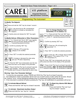
cod. +050003850 - rel. 3.2 - dated 01.04.2008
PB00* - powercompact
3 VA, 50 mA~ max.
6 VA, 50 mA~ max.
3 VA, 300 mA~ max.
Utilizzare esclusivamente
trasformatore TRA12VDE00 fusibile
nel secondario 315 mA ritardato
rinforzato
6 mm in aria, 8 superficiali
3750 V isolamento
principale
3 mm in aria, 4 superficiali
1250 V isolamento
da garantire esternamente con trasformatore di sicurezza
principale
3 mm in aria, 4 superficiali
1250 V isolamento
S1
S2
DI1/S3
NTC o PTC a seconda del modello
NTC o PTC a seconda del modello
contatto pulito, resistenza contatto < 10 Ω, corrente di chiusura 6 mA NTC o PTC a seconda del modello DI2 / S4
contatto pulito, resistenza contatto < 10 Ω, corrente di chiusura 6 mA
NTC o PTC a seconda del modello
Ingressi
Distanza massima sonde ed ingressi digitali minore di 10 m
Nota: nell’installazione tenere separati i collegamenti di alimentazione e dei
carichi dai cavi delle sonde, ingressi digitali, display ripetitore e supervisore.
NTC std. CAREL 10 kΩ a 25 °C, range da –50T90 °C
errore di misura:
1 °C nel range da –50T50 °C
3 °C nel range da –50T90 °C
Tipo sonda NTC alta 50 kΩ a 25 °C, range da –40T150 °C
temperatura
errore di misura:
1,5 °C nel range da –20T115 °C
4 °C nel range esterno a -40T150 °C
PTC std. CAREL 985 Ω a 25 °C, range da -50T150 °C
(modello specifico) errore di misura
2 °C nel range da –50T50 °C
4 °C nel range da –50T150 °C
a seconda del modello
EN60730-1
UL 873
250 V~
cicli di 250 V~ manovra
5 A *
5 (1) A 100000 5 A resistivi 1 FLA 6 LRA C 300
8 A *
8 (4) A su N.O. 100000 8 A resistivi 2 FLA 12 LRA 6 (4) A su N.C.
C300
2 (2) A se collegati
contemporaneamente
Uscite relè
contatti N.C. e N.O.
16 A*10 (4) A fino a 60 °C su N.O. 100000
12 A resistivi 5FLA
cicli di
manovra
30000
30000
30000
12 (2) A su N.O. e N.C.
30 LRA C300
2 Hp
10 (10) A
100000 12 A resistivi 12 FLA 72 LRA 30000
isolamento rispetto
rinforzato
la bassissima tensione
6 mm in aria, 8 superficiali, 3750 V isolamento
isolamento tra le uscite relè
principale
3 mm in aria, 4 superficiali 1250 V isolamento
* relè non adatti per carichi fluorescenti (neon,...) che utilizzino starter (ballast) con condensatore di rifasamento. Lampade fluorescenti con dispositivi di controllo elettronici o senza condensatore di rifasamento possono
essere utilizzate, compatibilmente con i limiti di funizionamento specificati per ogni tipo di relè.
Connessioni
Tipo connessione
Sezioni
Corrente massima
a vite fissi
per cavi da 0,5 a 2,5 mm2 12 A
estraibile per blocchetti a vite
faston con contatto a crimpare
il corretto dimensionamento dei cavi di alimentazione e di collegamento tra lo
strumento e i carichi è a cura dell’installatore.
Nella situazione di max carico e di max temp. di funzionamento sarà necessario
utilizzare cavi adatti al funzionamento fino a 105 °C.
Contenitore
plastico
dimensioni 36x167x75 mm
profondità incasso 64 mm
a pannello liscio rigido ed indeformabile mediante viti dal frontale
dima di foratura
dimensioni 29x138,5 mm
Montaggio
interasse viti di fissaggio 153,5 mm
viti di fissaggio
a testa svasata con diametro massimo del
filetto 3,9 mm
Contenitore
plastico
dimensioni 39,4x183x75 mm
(versione wide)
profondità incasso 63 mm
a pannello liscio rigido ed indeformabile mediante viti dal frontale o staffe
dima di foratura
dimensioni da 138,5x29 a 150x31
Montaggio
interasse viti di fissaggio 165 mm oppure
(versione wide)
153,5 mm
viti di fissaggio
a testa svasata con diametro massimo del
filetto 3,9 mm per interasse da 165 mm;
per interasse da 153 a testa piana diametro
massimo del filetto 3 mm
cifre 3 digit LED
Display
visualizzazione
da –99 a 999
stati di funzionamento
indicati con icone grafiche sul display
Tastiera
8 tasti in gomma siliconica
Ricevitore infrarossi
disponibile in funzione del modello
Orologio con batteria tampone disponibile in funzione del modello
Buzzer
disponibile in tutti i modelli
errore a 25 °C
±10 ppm (±5,3 min/anno)
errore nel range di temperatura -10T60 °C
-50 ppm (-27 min/anno)
Orologio
invecchiamento
< ±5 ppm (±2,7 min/anno)
tempo di scarica
6 mesi tipico (8 mesi max.)
tempo di ricarica 5 ore tipico (< di 8 ore max.)
Temperatura di funzionamento
-10T65 °C
Umidità di funzionamento
<90% U.R. non condensante
Temperatura di immagazzinamento
-20T70 °C
Umidità di immagazzinamento
<90% U.R. non condensante
Grado di protezione frontale
montaggio su pannello liscio ed indeformabile con guarnizione IP65
Inquinamento ambientale
2 situazione normale
PTI dei materiali di isolamento
circuiti stampati 250, plastica e materiali isolanti 175
Periodo delle sollecitazioni elettriche delle parti isolanti Lungo
Categoria di resistenza al fuoco
categoria D e categoria B (UL 94-V0)
Classe di protezione contro le sovratensione
categoria II
Tipo di azione e disconnessione
contatti relè 1B (microdisconnesione)
Costruzione del dispositivo di comando
dispositivo di comando incorporato, elettronico
Classificazione secondo la protez. contro le scosse elettriche Classe II per mezzo di appropriata incorporazione
Dispositivo destinato ad essere tenuto in mano o incorporato no
in apparecchiatura destinata ad essere tenuta in mano
Classe e struttura del software
Classe A
Pulizia frontale dello strumento
utilizzare esclusivamente detergenti neutri e acqua
Interfaccia seriale per rete CAREL
Esterna, disponibile in tutti i modelli
Interfaccia per display ripetitore
Esterna, disponibile nel modello con alimentazioni H e 0
Massima distanza tra interfaccia e display
10 mt
Chiave di programmazione
Disponibile in tutti i modelli
La gamma powercompact equipaggiata con sonda modello NTC standard CAREL, risulta conforme alla
norma EN 13485 relativa ai termometri per la misurazione della temperatura dell'aria per applicazioni su unità
di conservazione e di distribuzione di alimenti refrigerati, congelati, surgelati e dei gelati. Designazione dello
strumento: EN13485, aria, S, A, 1, -50T90°C. La sonda NTC standard CAREL è identificabile per il codice
stampato laser nei modelli "WP", o per la sigla "103AT-11" nei modelli "HP", entrambi visibili nella parte sensore.
Normative di sicurezza: conforme alle normative europee in materia.
Precauzioni d’installazione:
• i cavi di collegamento devono garantire l’isolamento fino a 90 °C;
• bloccare adeguatamente i cavi di conness. delle uscite per evitare contatti con componenti in bassissima tensione.
Montaggio a pannello/Panel mounting:
powercompact:
Montaggio a pannello: mediante due staffe plastiche a scorrimento
Panel mounting: by two lateral sliding plastic brackets.
1
2
Visualizzazione
Powercompact monta un display con LED a tre cifre per le temperature e icone luminose per la visualizzazione
degli stati di funzionamento. Può essere collegato, tramite l’opportuna interfaccia, un ulteriore display visualizzatore, utilizzato per esempio per la lettura della terza sonda.
Segnalazioni sul display
Icona Funzione
Normale funzionamento
Start up
ON
OFF
lampeggiante
COMPRESS. compressore acceso compressore spento compressore richiesto
VENTILATORE ventilatore acceso ventilatore spento
ventilatore richiesto
SBRINAMENTO sbrinamento in atto sbrinam. non richiesto sbrinamento richiesto
AUX
uscita ausiliaria
uscita ausiliaria
attiva funzione
AUX attiva
AUX non attiva
anti-sweat heater
ALLARME
allarme esterno
nessun allarme
allarmi in funz. norm.
ritardato (prima presente (es. alta/bassa temp.)
dello scadere del
o allarme da ingresso
tempo ‘A7’) digit. esterno
immediato o ritardato.
OROLOGIO se è stato impostato non è presente
allarme orologio ON se
almeno uno sbrinam. alcuno sbrinamento Real-Time
temporizzato
temporizzato Clock presente
LUCE
uscita ausiliaria
uscita ausiliaria
attiva funzione
LUCE attiva
LUCE non attiva
anti-sweat heater
ASSISTENZA
nessun
malfunzionamento
malfunzionamento
(es. errore EEPROM
o sonde guaste)
HACCP
funzione HACCP
funzione HACCP
allarme HACCP
abilitata non abilitata memorizzato (HA e/o HF)
CICLO
funzione CICLO
funzione CICLO
funzione CICLO
CONTINUO
CONTINUO attivata CONTINUO non attivata CONTINUO richiesta
Tab. 2
Se lampeggia indica una richiesta di attuazione non eseguibile fino allo scadere delle temporizzazioni che la
ritardano.
Pulsanti sulla tastiera
Icona Tasto
Normale funzionamento
Start-up
Richiesta
Pressione del singolo Pressione combinata
assegnazione
tasto ad altri tasti automatica
indirizzo
HACCP entra nel menù di
visualizzazione e
cancellazione degli
allarmi HACCP
ON/OFF premuto per più di 5 s,
abilita/disabilita l’unità
PRG/
premuto per più di • premuto per più di 5 s insieme premuto
premuto
MUTE 5 s, dà accesso al menu al tasto SET, dà accesso al menu per più di 5 s per più di 1 s
di impostazione dei di impostazione dei parametri di allo start-up, entra nella
parametri di tipo “F” tipo “C” (Configuraz.) o al
attiva la
procedura di
(Frequenti) in caso download di parametri procedura assegnazione
d’allarme: tacita l’allarme • se premuto per più di 5 s insieme di impostaz. automatica
acustico (buzzer) e al tasto UP/CC resetta gli eventuali dei parametri dell’indirizzo
disattiva il relé d’ allarme allarmi a ripristino manuale
di Default
seriale
UP/CC premuto per più di
• premuto per più di 5 s
5 s, attiva/disattiva insieme al tasto SET, attiva la
il funzionamento a procedura di stampa del report
ciclo continuo (funzione disponibile ma gestione
da implementare)
• premuto per più di 5 s
insieme al tasto PRG/MUTE
resetta gli eventuali allarmi a
ripristino manuale presenti
LUCE
premuto per più di 1 s,
attiva/disattiva l’uscita
AUX 2
AUX
se premuto per più di
1 s, attiva/disattiva
l’uscita AUX 1
DOWN/ premuto per più di
DEF 5 s, attiva/disattiva uno
sbrinamento manuale
SET
premuto per più di
• premuto per più di 5 s
1 s, visualizza e/o insieme al tasto PRG/MUTE, dà
imposta il set point accesso al menu di impostazione
dei param. di tipo “C” (Configuraz.)
o al download dei parametri
• premuto per più di 5 s insieme
al tasto UP/CC, attiva la procedura
di stampa del report (funzione
disponibile ma gestione da
implementare) Tab. 3
Impostazioni del set point (valore di temperatura desiderato)
Per visualizzare o impostare il set point procedere come segue:
1) premere il tasto set per più di 1 secondo per visualizzare il set point;
2) incrementare o decrementare il valore del set point, rispettivamente, con i tasti
raggiungere il valore desiderato;
3) premere di nuovo il tasto set per confermare il nuovo valore.
e
fino a Ripristino allarmi a reset manuale
È possibile resettare tutti gli allarmi a ripristino manuale premendo insieme i tasti
e
per più di 5 s.
Sbrinamento manuale
Oltre allo sbrinamento automatico è possibile attivare uno sbrinamento manuale se esistono le condizioni di
per 5 secondi.
temperatura premendo il tasto
Tasto di ON/OFF
Premendo il tasto
per 5 secondi si può attivare/disattivare l’unità. Quando il controllo è disattivato si trova in
stato di stand-by, quindi, per poter eseguire manutenzione sull’apparato è necessario togliere tensione.
Funzione HACCP
Il powercompact è conforme alle normative HACCP in quanto permette il monitoraggio della temperatura
del cibo conservato. Allarme HA= superamento soglia massima: vengono inoltre memorizzati fino a tre eventi
HA (HA, HA1, HA2) rispettivamente dal più recente (HA) al più vecchio (HA2) e una segnalazione HAn che
visualizza il numero di eventi HA intervenuti. Allarme HF= mancata tensione per più di 1 minuto e superamento
soglia massima AH: vengono inoltre memorizzati fino a tre eventi HF (HF, HF1, HF2) rispettivamente dal più
recente (HF) al più vecchio (HF2) e una segnalazione HFn che visualizza il numero di eventi HF intervenuti.
Settaggio allarme HA/HF: parametro AH (soglia di alta temp.); Ad e Htd (Ad + Htd = ritardo allarme HACCP).
Visualizzazione dei dettagli: Premere il tasto HACCP per accedere ai parametri HA o HF e scorrere i tasti
. Cancellazione allarmi HACCP: premere in qualsiasi momento per 5 s dall’interno del menù il tasto
o
HACCP, un messaggio “res” indicherà l’avvenuta cancellazione dell’allarme attivo. Per cancellare anche gli allar.
mi memorizzati premere per 5 s la combinazione di questi due tasti: HACCP e
Ciclo continuo
Per attivare la funzione di ciclo continuo premere il tasto
per più di 5 s.
Durante il funzionamento in ciclo continuo, il compressore continua a funzionare durante tutta la sua durata e
si fermerà per time-out ciclo o per raggiungimento della temperatura minima prevista (AL = soglia di allarme di
minima temperatura). Settaggio ciclo continuo: parametro “cc” (durata ciclo continuo): “cc”= 0 mai attivo; parametro
“c6” (esclusione allarme dopo ciclo continuo): esclude o ritarda l’allarme di bassa al termine del ciclo continuo.
Procedura di impostazione dei parametri di default
Per impostare i parametri di default del controllo si procede in questo modo:
• Se “Hdn" = 0: 1) togliere tensione allo strumento; 2) ridare tensione allo strumento tenendo premuto il
fino alla comparsa del messaggio “Std" sul display.
tasto
Nota: i valori di default vengono impostati solo per i parametri visibili (C e F). Per maggiori dettagli vedere la
tabella Riepilogo parametri di funzionamento.
• Se “Hdn" < > 0: 1) togliere tensione allo strumento; 2) ridare tensione allo strumento tenendo premuto il tasto fino alla comparsa del valore 0; 3) selezionare il set di parametri di Default, tra 0 e “Hdn che si vuole e
; 4) premere il tasto
fino alla comparsa del messaggio impostare per mezzo dei tasti
“Std” sul display.
Assegnazione automatica indirizzo seriale
È una particolare procedura che permette, attraverso un applicativo installato su un PC, di impostare e gestire
in maniera molto semplice gli indirizzi di tutti gli strumenti (che prevedono tale funzione) connessi alla rete CAREL.
La procedura da seguire è molto semplice:
1)Attraverso il software remoto si attiva la procedura di “Definizione rete”; l’applicativo inizia a inviare alla rete CAREL un particolare messaggio (‘<!ADR>’) contenente l’indirizzo di rete.
su uno strumento si attiva il riconoscimento di questo messaggio, il quale autoimposta 2)Premendo il pulsante
il proprio indirizzo al valore richiesto e invia un messaggio di conferma all’applicativo contenente codice macchina e revisione firmware (messaggio ‘V’). Al riconoscimento del messaggio inviato dall’applicativo remoto, lo strumento visualizza per 5 s il messaggio ‘Add’ sul display, seguito dal valore dell’indirizzo seriale assegnato.
3)L’applicativo, una volta ricevuto il messaggio di conferma da una delle macchine, salva le informazioni ricevute nel proprio database, incrementa l’indirizzo seriale e ricomincia a inviare il messaggio ‘<!ADR>’.
4)A questo punto è possibile ripetere la procedura dal punto 2 su un’altra macchina fino a definire gli indirizzi di tutta la rete.
Nota: una volta assegnato l’indirizzo su uno strumento, l’operazione, per ragioni di sicurezza, viene inibita sullo
stesso per 1 minuto durante il quale non sarà possibile riassegnare un diverso indirizzo allo strumento.
powercompact PB wide:
Accesso ai parametri di configurazione (tipo C)
PST00VR100: interfaccia display ripetitore/repeater display interface
Montaggio a pannello: mediante due viti a testa svasata con diametro max 3,9 mm.
Panel mounting: by two countersunk screws, max. diameter 3.9 mm.
1
tipo Pozidriv
Pozidriv type
2
1) Premendo contemporaneamente i tasti
e set per più di 5 secondi, sul display comparirà “00” (la richiesta della password)
o
visualizzare il numero “22” (password di accesso ai parametri).
2) Con i tasti
3) Confermare con il tasto set.
4) Sul display compare il primo parametro “C” modificabile.
3
Accesso ai parametri di configurazione (tipo F)
NON ECCEDERE
NEL SERRAGGIO
DON’T TIGHTEN
TOO MUCH
1) Premendo il tasto
per più di 5 secondi (in caso di allarme tacitare prima il buzzer), sul display compare il primo parametro “F” modificabile.
Modifica dei parametri
Fig. 1
max 2.5
Connessioni opzionali/Optional connections:
IROPZKEY**:
Chiave di programmazione
Programming key
IROPZDSP00:
Opzione interfaccia display
Display interface option
IROPZ485S0:
Interfaccia scheda seriale
RS485 intelligente
Smart serial board
interface RS485
Fig. 2
Dopo aver visualizzato il parametro, sia esso di tipo “C” o di tipo “F”, si procede nel seguente modo:
o
scorrere i parametri fino a raggiungere quello da modificare; lo scorrimento è 1) Con i tasti
accompagnato dall’accensione di una icona sul display che rappresenta la categoria di appartenenza del parametro.
per visualizzare un menù che permetta di raggiungere velocemente la 2) In alternativa, premere il tasto
categoria di parametri da modificare.
e
compaiono sul display i codici delle varie categorie di
3) Scorrendo il menù con i tasti
parametri (vedi tabella Riepilogo parametri di funzionamento) accompagnati dall’accensione della relativa icona sul display (se presente).
4) Una volta raggiunta la categoria desiderata premere set per ritrovarsi direttamente sul primo parametro della categoria scelta (nel caso non vi sia alcun parametro visibile, la pressione del tasto set non avrà alcun effetto).
.
5) A questo punto è possibile continuare a consultare i parametri o tornare al menu “Categorie” con il tasto
6) Premere set per visualizzare il valore associato al parametro.
o
7) Incrementare o decrementare il valore rispettivamente con i tasti
8) Premere set per memorizzare temporaneamente il nuovo valore e tornare alla visualizzazione del parametro.
9) Ripetere le operazioni dal punto 1 o dal punto 2.
10)Se il parametro è dotato di sottoparametri premere set per visualizzare il primo sottoparametro.
o
per visualizzare tutti i sottoparametri.
11)Premere i tasti
12)Premere set per visualizzare il valore associato.
o
.
13)Incrementare o decrementare il valore rispettivamente con i tasti
14)Premere set per memorizzare temporaneamente il nuovo valore e tornare alla visualizzazione del codice del sottoparametro.
per ritornare alla visualizzazione del parametro padre.
15)Premere
Accesso diretto ai parametri tramite la selezione della categoria
È possibile accedere ai parametri di configurazione, oltre al modo già descritto, anche tramite la categoria (vedi
icone e abbreviazioni nella tabella sottostante) secondo la lista a display in corrispondenza del nome e dell’icona corrispondente. Per accedere direttamente alla selezione dei parametri raggruppati per categoria ,e per modificare il parametro premere set,
,
premere il tasto
Categoria
Parametri sonda
Parametri regolazione
Parametri compressore Parametri sbrinamento Parametri allarmi Parametri ventole Parametri configurazione Parametri HACCP Parametri RTC Parametri
/
r
c
d
A
F
H configurazione H HACCP rtc Scritta
‘Pro’
‘CtL’
‘CMP’
‘dEF’
‘ALM’
‘FAn’
‘CnF’
‘HcP’
‘rtc’
Icona
Configurazione Sonde (/A2.../A5)
Tab. 4
Nella serie powercompact questi parametri permettono di configurare la modalità di funzionamento delle sonde:
0 = sonda assente; 1 = sonda prodotto (utilizzata per sola visualizzazione); 2 = sonda sbrinamento;
3 = sonda condensazione; 4 = sonda antifreeze.
Configurazione ingresso digitale (A4, A5, A9)
Nella serie powercompact questo param. e il modello di controllo utilizzato, definiscono il significato dell’ingresso digitale:
0 = ingresso non attivo;
1 = allarme esterno immediato normalmente chiuso: aperto = allarme;
2 = allarme esterno ritardato normalmente chiuso;
3 = abilitazione sbrinamento da contatto esterno: aperto = disabilitato (è possibile collegare un contatto esterno all’ingresso multifunzione per abilitare o inibire lo sbrinamento).
4 = inizio sbrinamento in chiusura del contatto esterno;
5 = switch porta con spegnimento di compressore e ventole: aperto = porta aperta;
6 = ON/OFF remoto: chiuso = ON;
7 = switch-tenda: chiuso = tenda abbassata;
8 = ingresso pressostato di bassa pressione per pump-down: aperto = bassa pressione;
9 = switch porta con spegnimento delle sole ventole: aperto = porta aperta;
10 =funzionamento direct/reverse: aperto = direct;
11 =sensore di luce;
12 =attivazione uscita AUX (se configurata con i parametri H1 o H5): apertura = disattivazione;
13 =switch porta con OFF di compressore e ventole con luce non gestita;
14 =sitch porta con OFF ventole con luce non gestita.
Configurazione uscite relè AUX1 e AUX2 (H1 e H5)
Stabilisce se AUX1 (H1) e AUX2 (H5)(presenti solamente se previsti dal modello) sono usati come uscita ausiliaria (es. ventola antiappannante o altro attuatore ON/OFF), come uscita di allarme, come uscita luce,
come attuatore di defrost per l’evaporatore ausiliario, come comando per la valvola di pump-down o come uscita per la ventola condensatore.
0 = uscita di allarme: normalmente eccitato; il relè si diseccita al verificarsi di un allarme;
1 = uscita di allarme: normalmente diseccitato; il relè si eccita al verificarsi di un allarme;
2 = uscita ausiliaria;
3 = uscita luce;
4 = uscita defrost evaporatore ausiliario;
5 = uscita valvola di pump-down;
6 = uscita ventola condensatore;
7 = uscita compressore ritardato;
8 = uscita ausiliaria con spegnimento in OFF;
9 = uscita luce con spegnimento in OFF;
10 =uscita disabilitata;
11 =uscita reverse in regolazione con zona neutra;
12 =uscita gradino secondo compressore;
13 =uscita gradino secondo compressore con rotazione.
Avvertenza: la modalità H1/H5=0 è utile per segnalare lo stato di allarme anche in caso di assenza di alimentazione.
” a quest’uscita, impostare
Nota: Nei modelli dotati di una sola uscita ausiliaria, per associare il tasto “
H1= 10 e H5= 3. É necessario associare il relè assegnato all’aux 1 all’uscita ausiliaria 2; l’operazione si può fare
utilizzando il kit di programmazione PSOPZPRG00 e la chiave di programmazione PSOPZKEY00/A0.
SimboloCod. Parametro
Modelli U.M. Tipo Min Max
F0 Gestione ventilatori
F flag C
0
2
0: Ventilatori sempre accesi
1: Ventilatori accesi in base alla differenza tra la sonda virtuale di regolazione e la
temperatura evaporatore
2: Ventilatori accesi in base alla temperatura dell'evaporatore
F1 Temperatura accensione ventilatore
F °C/°F F
-50 200
F2 Ventilatore off con compressore off
F flag C
0
1
0: Ventilatori funzionano sempre
1: Ventilatori fermi se compressore fermo
F3 Ventilatore in sbrinamento
F flag C
0
1
0: Ventilatori funzionano durante lo sbrinamento
1: Ventilatori non funzionano durante lo sbrinamento
Fd Spegnimento ventole dopo gocciolamento
F min F
0
15
F4 Temperatura spegnimento ventilatore condensatore MSYF °C/°F C
-50 200
F5 Differenziale accensione ventilatore condensatore MSYF °C/°F C
0.1 20
Def.
0
Simbolo Cod.
H0
H1
H2
Def.
1
1
0= nessun evento; 1...7= lunedì...domenica; 8= da lunedì a venerdì; 9= da lunedì a sabato; 10= da sabato a
domenica; 11= tutti i giorni.
Riepilogo parametri di funzionamento
Def.
22
4
0
0
0
0
1
H3
H4
H5
H6
H8
H9
Hdh
•
•
•
•
0
0
2
0
HAn
HA
y__
M__
d__
h__
n__
t__
HA1
HA2
HFn
HF
y__
M__
d__
h__
n__
t__
HF1
HF2
Htd
0
0
0.0
0.0
0.0
0.0
Parametro
Modelli U.M. Tipo Min Max Def.
Set point temperatura
MSYF °C/°F F
r1
r2 0.0
Delta Regolatore
SYF °C/°F F
0.1 20 2.0
Zona neutra
SYF °C/°F C
0.0 60 4.0
Delta regolatore reverse con zona neutra
SYF °C/°F C
0.1 20 2.0
Set minimo ammesso
MSYF °C/°F C
-50 r2 -50
Set massimo ammesso
MSYF °C/°F C
r1 200 60
Modalità di funzionamento
SYF flag C
0
2 0
0: Termostato Direct (freddo) con controllo sbrinamento
1: Termostato Direct (freddo)
2: Termostato riverse (caldo)
Variazione automatica set point notturno
MSYF °C/°F C
-20 20 3.0
Abilitazione monitoraggio temperatura
MSYF flag C
0
1 0
0: Disabilitato
1: Abilitato
Intervallo monitoraggio temperatura
MSYF ore
F
0 999 Massima temperatura letta
MSYF °C/°F F
-
-
Minima temperatura letta
MSYF °C/°F F
-
-
-
Simbolo Cod.
c0
c1
c2
c3
c4
cc
c6
c7
c8
Parametro
Modelli U.M. Tipo Min Max
Ritardo start compressore, ventole e aux SYF min C
0
15
zona neutra all'accensione
Tempo minimo tra accensioni successive
SYF min C
0
15
Tempo minimo di Off del compressore
SYF min C
0
15
Tempo minimo di On del compressore
SYF min C
0
15
Duty setting
SYF min C
0 100
Durata ciclo continuo
SYF ore C
0
15
Esclusione allarme dopo ciclo continuo
SYF ore
C
0 250
Tempo massimo di pump down
SYF
s
C
0 900
Ritardo start comp. dopo apert. valvola PD SYF
s
C
0
60
(impostato 0 di fabbrica e non visibile)
Abil. funz. di autostart con funz.in PD
SYF flag C
0
1
Selez. pump down a tempo o pressione
SYF flag C
0
1
0: Pump down a pressione
1: Pump down a tempo
Ritardo secondo compressore
SYF
s
C
0 250
Def.
0
SimboloCod. Parametro
Modelli U.M. Tipo Min Max
d0 Tipo di defrost
SYF flag C
0
4
0: Sbrinamento a resistenza in temperatura
1: Sbrinamento a gas caldo in temperatura
2: Sbrinamento a resistenza a tempo
3: Sbrinamento a gas caldo a tempo
4: Sbrinamento termostato a resistenza a tempo
dI Intervallo tra i defrost
SYF ore
F
0 250
dt1 Temperatura di fine defrost evap.
SYF °C/°F F
-50 200
dt2 Temperatura di fine defrost evap. aux
SYF °C/°F F
-50 200
dP1 Durata massima defrost evaporatore
SYF min F
1 250
dP2 Durata massima defrost evap. aux
SYF min F
1 250
d3 Ritardo inserimento defrost
SYF min C
0 250
d4 Abilitazione defrost allo start up
SYF flag C
0
1
0: Non c'è sbrinam. all'accensione dello strumento 1: Viene eseguito uno sbrinamento all'accensione
d5 Ritardo defrost allo start up
SYF min C
0 250
d6 Blocco display durante il defrost
SYF
-
C
0
2
0: Visualizzazione alternativa scritta dEF e valore sonda
1: Visualizzazione dell'ultima temperatura mostrata
2: Visualizzazione fissa scritta dEF
dd Tempo di gocciolamento dopo il defrost
SYF min F
0
15
d8 Esclusione allarmi dopo il defrost
SYF ore
F
0 250
d8d Esclusione allarmi dopo porta aperta
SYF min C
0 250
d9 Priorità defrost su protezioni compressore
SYF flag C
0
1
0: Vengono rispettati i tempi di protezione c1, c2 e c3
1: Non vengono rispettati i tempi di protezione c1, c2 e c3
d/1 Visualizzazione sonda defrost 1
MSYF °C/°F F
-
-
d/2 Visualizzazione sonda defrost 2
MSYF °C/°F F
-
-
dC Base dei tempi per defrost
SYF flag C
0
1
0: dI in ore, dP1 e dP2 in minuti
1: dI in minuti, dP1 e dP2 in secondi
d10 Running time del compressore
SYF ore C
0 250
d11 Soglia di temperatura di running time
SYF °C/°F C
-20 20
d12 Defrost avanzati
SYF
-
C
0
3
dn Durata nominale defrost
SYF
-
C
1 100
dH Fattore proporzionale variazione di dI
SYF
-
C
0 100
Def.
0
Simbolo Cod. Parametro
Modelli U.M. Tipo Min Max
A0 Differenziale allarmi e ventole
MSYF °C/°F C
0.1 20
A1 Tipo di soglia AL e AH
MSYF flag C
0
1
0: AL e AH soglie relative al set point 1: AL e AH soglie assolute
AL Soglia di allarme di bassa temperatura
MSYF °C/°F F
-50 200
AH Soglia di allarme di alta temperatura
MSYF °C/°F F
-50 200
Ad Ritardo segnalazione bassa e alta temp.
MSYF min F
0 250
A4 Configurazione ingresso digitale 1(DI1)
SYF
-
C
0
14
M
-
C
0
14
0: Ingresso non attivo
1: Allarme esterno immediato
2: Allarme esterno con ritardo attuazione
3: Se modello M selezione sonde
Def.
2.0
0
0
0
0
0
0
2
0
5
0
0
4
8
4.0
4.0
30
30
0
0
0
1
2
1
0
0
0
0
1.0
0
65
50
0.0
0.0
120
0
3
td1
d__
h__
n__
td2
td3
td4
td5
td6
td7
td8
ton
d__
h__
n__
toF
d__
h__
n__
tc
y__
M__
d__
u__
h__
n__
1
1
40
5.0
3
1
•
•
• •
•
• •
• •
• •
• •
Funzionalità tastiera
"•" = Disabilitati
Codice abilitazione telecomando
MSYF
-
C
0 255 0
Disabilitazione buzzer
MSYF flag C
0
1 0
0: Buzzer abilitato
1: Buzzer disabilitato
Funzionalità relè 5
MSYF flag C
0
13 1
Come H1
Blocco tasti
MSYF
-
C
0 255 0
0: Tutti i tasti abilitati
Selezione uscita attivazione con fascia oraria
MSYF flag C
0
1 0
0: Fascia oraria legata all'uscita configurata luce
1: Fascia oraria legata all'uscita configurata aux
Abilitazione variazione del set point con fascia oraria MSYF flag C
0
1 0
0: Variazione set point con fascia oraria disabilitata
1: Variazione set point con fascia oraria abilitata
Offset anti-sweat heater
MSYF °C/°F C
-50 200 0.0
Modelli
Numero di eventi HA intervenuti
MSYF
Data/ora dell' ultimo evento HA
MSYF
Anno
Mese
Giorno
Ora
Minuto
Durata
Data/ora del penultimo evento HA
MSYF
Data/ora del terzultimo evento HA
MSYF
Numero di eventi HF intervenuti
MSYF
Data/ora dell' ultimo evento HF
MSYF
Anno
Mese
Giorno
Ora
Minuto
Durata
Data/ora del penultimo evento HF
MSYF
Data/ora del terzultimo evento HF
MSYF
Ritardo allarme HACCP
MSYF
Simbolo Cod. Parametro
0
5.0
1
•
•
Simbolo Cod. Parametro
Simbolo Cod.
St
rd
rn
rr
r1
r2
r3
r4
r5
rt
rH
rL
c9
c10
c11
Parametro
Modelli U.M. Tipo Min Max
Indirizzo seriale
MSYF
-
C
0 207
Funzionalità uscita AUX1
MSYF flag C
0
13
0: Uscita di allarme normalmente eccitato
1: Uscita di allarme normalmente diseccitato
2: Uscita ausiliario
3: Uscita luce
4: Uscita sbrinamento evaporatore ausiliario
5: Uscita valvola di pump down
6: Uscita ventola condensatore
7: Uscita compressore ritardato
8: Uscita ausiliaria con disattivazione nello stato di OFF
9: Uscita luce con disattivazione nello stato di OFF
10: Nessuna funzione associata all'uscita
11: Uscita riverse in regolazione con zona neutra
12: Uscita gradino secondo compressore 13: Uscita gradino secondo compressore con rotazione
Disabilitazione tastiera/ir
MSYF flag C
0
6
0
1
2
3
4
5
6
Data e giorno per evento di defrost (parametri td1...td8)
U.M. = Unità di misura; Def. = Valore di fabbrica.
Simbolo Cod. Parametro
Modelli U.M. Tipo Min Max
Pw Password MSYF
-
C
0 200
/2
Stabilità misura
MSYF
-
C
1
15
/3
Rallentamento visualizzazione sonda
MSYF
-
C
0
15
/4
Sonda virtuale
MSYF
-
C
0 100
/5
Selezione gradi °C o°F
MSYF flag C
0
1
0 : °C
1 : °F
/6
Visualizzazione punto decimale
MSYF flag C
0
1
0: con decimo di grado
1: senza decimo di grado
/tI
Visualizzazione su terminale interno
MSYF
-
C
1
7
1: sonda virtuale
2: sonda 1
3: sonda 2
4: sonda 3
5: sonda 4
6: sonda 5
7: set point
/tE Visualizzazione su terminale esterno
MSYF
-
C
0
6
0: terminale remoto non presente
1: sonda virtuale
2: sonda 1
3: sonda 2
4: sonda 3
5: sonda 4
6: sonda 5
/P
Selezione tipo di sonda
MSYF
-
C
0
2
0: NTC standard con range -50T90 °C
1: NTC enhanced con range -40T150 °C
2: PTC standard con range -50T150 °C
/A2 Configurazione sonda 2 (S2)
YF
-
C
0
4
MS
-
C
0
4
0: Sonda assente
1: Sonda prodotto (solo visualizzazione)
2: Sonda sbrinamento
3: Sonda condensazione
4: Sonda antifreeze
/A3 Configurazione sonda 3 (S3/ DI1)
MSYF
-
C
0
3
Come /A2
/A4 Configurazione sonda 4 (S4/DI2)
MSYF
-
C
0
3
Come /A2
/A5 Configurazione sonda 5 (S5/DI3)
MSYF
-
C
0
3
Come /A2
/c1 Calibrazione sonda 1
MSYF °C/°F C
-20 20
/c2 Calibrazione sonda 2
MSYF °C/°F C
-20 20
/c3 Calibrazione sonda 3
MSYF °C/°F C
-20 20
/c4 Calibrazione sonda 4
MSYF °C/°F C
-20 20
3: Altri modelli abilitazione sbrinamento
4: Inizio sbrinamento
5: Switch porta con off di compressore e ventilatori
6: On/off remoto
7: Switch tenda
8: Pressostato di bassa pressione
9: Switch porta con off dei soli ventilatori
10: Direct/riverse
11: Sensore di luce 12: Attivazione uscita aux
13: Switch porta con spegnimento di compressore
e ventole, luce non gestita
14: Switch porta con spegnimento di solo le
ventole, luce non gestita
Configurazione ingresso digitale 2 (DI2)
MSYF
-
C
0
14 0
Come A4
Blocco compressore da allarme esterno
SYF min C
0 100 0
Ritardo rilevazione allarme esterno
SYF min C
0 250 0
Abilitazione allarmi Ed1 ed Ed2 SYF flag C
0
1 0
Segnalazioni Ed1 e Ed2 abilitate
0
Segnalazioni Ed1 e Ed2 disabilitate
1
Configurazione ingresso digitale 3 (DI3)
MSYF
-
C
0
14 0
Come A4
Modalità gestione luce con switch porta
MSYF flag C
0
1 0
Allarme alta temperatura condensatore
SYF °C/°F C
0.0 200 70.0
Differenziale allarme alta temp. cond.
SYF °C/°F C
0.1 20 10
Ritardo allarme alta temperatura condensatore
SYF min C
0 250 0
Tempo spegnimento con sensore di luce
SYF
s
C
0 250 0
Soglia di allarme antifreeze
MSYF °C/°F C
-50 200 -5.0
Ritardo allarme antifreeze
MSYF min C
0
15 1
Modifica da telecomando
Potenza
3 VA, 25 mA~ max.
DESCRIZIONE
telecomando infrarossi small
Interfaccia RS485 scheda seriale
Interfaccia RS485 scheda seriale con riconoscimento automatico della polarità +/interfaccia display remoto
display ripetitore remoto plug in range
display ripetitore remoto ir33 range display verde
display ripetitore remoto ir33 range display rosso
cavi di connessione al display ripetitore 1,5 m
cavi di connessione al display ripetitore 3 m
cavi di connessione al display ripetitore 5 m
chiave di programmazione parametri con batterie 12 V incluse
chiave di programmazione parametri con alimentatore esterno 230 Vac
chiave di programmazione parametri con memoria estesa e batterie 12 V incluse
chiave di programmazione parametri con memoria estesa e alimentatore esterno 230 Vac
kit programmazione chiave
Tab. 1
A5
A6
A7
A8
A9
Ado
Ac
AE
Acd
AF
ALF
AdF
Modifica set point
Modello Tensione
E
230 V~ (+10%, -15%), 50/60 Hz
230 V~ (+10%, -10%), 50/60 Hz (vers. 16 A, 8A, 8A)
A
115 V~ (+10%, -15%), 50/60 Hz 115 V~ (+10%, -10%), 50/60 Hz (vers. 16 A, 8A, 8A)
Alimentazione H
115...230 V~ (switching) (+10%,-15%), 50/60 Hz
0
12 V~ (+10%, -15%), 50/60 Hz 12 Vdc, 12...18 Vdc E, A, H isolamento rispetto alla bassissima tensione
Isolamento
isolamento rispetto alle uscite relè
garantito
dall’alimentazione
0
isolamento rispetto alla bassissima tensione
isolamento rispetto alle uscite relè
CODICE
IRTRRES000
IROPZ48500
IROPZ485S0
IROPZDSP00
PST00VR100 IR00RG0000
IR00RR0000
PSTCON01B0 PSTCON03B0 PSTCON05B0 PSOPZKEY00 PSOPZKEYA0 IROPZKEY00 IROPZKEYA0 VPMSTDKY*0 Per memorizzare definitivamente i nuovi valori dei parametri modificati premere il tasto
per più di 5 secondi,
uscendo così dalla procedura di modifica dei parametri. È possibile annullare tutte le modifiche ai parametri,
memorizzate temporaneamente in RAM, e tornare in “funzionamento normale” non premendo nessun tasto per 60
secondi, lasciando quindi scadere la sessione di modifica dei parametri per timeout.
, tutte le modifiche fatte ai
Nel caso venga tolta tensione allo strumento prima della pressione del tasto
parametri e temporaneamente memorizzate saranno perdute.
LUCE
ON/OFF
AUX
HACCP
PRG/MUTE (mute)
UP/CC
DOWN/DEF
SET
Modifica parametri F
CARATTERISTICHE TECNICHE
Memorizzazione dei nuovi valori assegnati ai parametri
Codici opzioni
Parametro “H2”
Modelli/Models PB00(S,Y,F,C,H)(0,6)(0,E,A,H)(N,R,C,B,A,M,L,T,P,Q,S,U,V,X,Y,Z)
(1,2,3,4,5,A,B,C,D,E,F)0
Modelli
Fascia oraria defrost 1
SYF
Giorno
Ora
Minuto
Fascia oraria defrost 2
SYF
Fascia oraria defrost 3
SYF
Fascia oraria defrost 4
SYF
Fascia oraria defrost 5
SYF
Fascia oraria defrost 6
SYF
Fascia oraria defrost 7
SYF
Fascia oraria defrost 8
SYF
Fascia oraria accensione luce/aux
SYF
Giorno
Ora
Minuto
Fascia oraria spegnimento luce/aux /
variazione set point
SYF
Giorno
Ora
Minuto
Impostazione Data/Ora RTC / variazione set point MSYF
Anno
Mese
Giorno del mese
Giorno della settimana
Ora
Minuto
U.M. Tipo Min Max Def.
-
C
0
-
C
anni
0
mesi
1
giorni
1
ore
0
min.
0
ore
0
-
C
-
-
C
-
-
C
0
-
C
-
anni
0
mesi
1
giorni
1
ore
0
min.
0
ore
0
-
C
-
-
C
0
min C
0
15
-
99
12
7
23
59
99
-
-
15
-
99
12
7
23
59
99
-
-
250
0
0
0
0
0
0
0
0
0
0
0
0
0
0
0
U.M. Tipo Min Max Def.
-
C
giorni
ore
min.
-
C
-
C
-
C
-
C
-
C
-
C
-
C
-
C
giorni
ore
min.
-
0
0
0
-
-
-
-
-
-
-
-
0
0
0
-
11
23
59
-
-
-
-
-
-
-
-
11
23
59
-
C
giorni
ore
min.
-
C
anni 0
mesi 1
giorni 1
giorni 1
ore
0
min. 0
-
0
0
0
-
0
1
1
1
0
0
-
11
23
59
-
99
12
31
7
23
59
0
0
0
0
0
0
0
0
0
0
1
1
6
0
0
Tab. 6
Avvertenza importante: affinchè i tempi impostati diventino immediatamente operativi, bisogna spegnere e
riaccendere lo strumento. Nel caso non si spenga lo strumento, la temporizzazione diventerà operativa al suo
successivo utilizzo, in fase di impostazione dei timer interni.
Tabella allarmi e segnalazioni: display, buzzer e relè
Di seguito la tabella che riporta gli allarmi e le segnalazioni del controllo, con relativa descrizione, stato del buzzer, del
relè di allarme e la modalità di ripristino.
Codice Icona sul Display Relè Allarme Buzzer Ripristino
‘rE’
lampeggiante
attivo
attivo automatico
‘E0’
lampeggiante
spento
spento automatico
‘E1’
lampeggiante
spento
spento automatico
‘E2’-3-4
lampeggiante
spento
spento automatico
‘___’
nessuna
spento
spento automatico
‘LO’
lampeggiante
attivo
attivo automatico
‘HI’
lampeggiante
attivo
attivo automatico
‘AFr’
lampeggiante
attivo
attivo manuale
‘IA’
lampeggiante
attivo
attivo automatico
‘dA’
lampeggiante
attivo
attivo automatico
‘dEF’
acceso
spento
spento automatico
‘Ed1’-2
nessuna
spento
spento automatico/ manuale ‘Pd’
lampeggiante
attivo
attivo autom./man.
‘LP’ lampeggiante attivo attivo autom./man. ‘AtS’
lampeggiante
attivo
attivo autom./man. ‘cht’
nessuna
spento
spento autom./man.
Descrizione
sonda virtuale di regolazione guasta
sonda ambiente S1 guasta
sonda sbrinamento S2 guasta
sonda S3-4-5 guasta
sonda non abilitata
allarme bassa temperatura
allarme alta temperatura
allarme antifreeze
allarme immediato da contatto esterno
allarme ritardato da contattoesterno
defrost in esecuzione
defrost su evaporatore 1-2 terminato
per timeout
allarme tempo massimo di pump-down
allarme di bassa pressione
autostart in pump-down
preallarme alta temp. condensatore allarme
‘CHT’
lampeggiante attivo attivo manuale alta temperat. condensatore
‘dor’
lampeggiante
attivo
attivo automatico allarme porta aperta per troppo tempo
‘Etc’ lampeggiante spento spento autom./man. real time clock guasto
‘EE’ lampeggiante spento spento automatico Errore Eeprom parametri macchina
‘EF’ lampeggiante spento spento automatico Errore Eeprom parametri di funzionam.
‘HA’ lampeggiante spento spento manuale allarme HACCP di tipo ‘HA’
‘HF’ lampeggiante spento spento manuale allarme HACCP di tipo ‘HF’
‘rCt’ Segnalazione Strumento abilitato alla programm. da telecomando
‘Add’ Segnalazione Procedura di assegnazione automatica indirizzo in corso
‘Prt’ Segnalazione Stampa del report in corso
‘LrH’ Segnalazione
Attivazione della procedura di bassa U.R.
‘HrH’ Segnalazione Attivazione della procedura di alta U. R.
‘ccb’ Segnalazione Richiesta inizio ciclo continuo
‘ccE’ Segnalazione Richiesta fine ciclo continuo
‘dFb’ Segnalazione Richiesta inizio defrost
‘dFE’
Segnalazione Richiesta fine defrost
‘On’ Segnalazione Passaggio a stato di ON
‘OFF’ Segnalazione Passaggio a stato di OFF
‘rES’ Segnalazione Reset allarmi a ripristino man.
Reset allarmi HACCP
Reset monitoraggio temp.
‘n1’...‘n6’ lampeggiante attivo attivo automatico Indica allarme sull’unità 1...6 presente nella rete
‘dnL’
Segnalazione
Segnala download in corso
‘d1’...‘d6’
lampeggiante
spento
spento
Segnala download con errori sull’unità 1...6
Tab. 6
Il buzzer viene attivato se abilitato dal parametro ‘H4’.
Il relè di allarme viene attivato se alle uscite ausiliarie AUX1 (H1) o AUX2 (H5) è stata assegnata alla funzione relè di
allarme (normalmente eccitato o diseccitato). Nota: il buzzer può essere disabilitato dal sistema di supervisione CAREL.
Smaltimento del prodotto
L'apparecchiatura (o il prodotto) deve essere oggetto di raccolta separata in conformità alle vigenti normative locali in materia di
smaltimento
AVVERTENZE IMPORTANTI: Il prodotto CAREL è un prodotto avanzato, il cui funzionamento è specificato nella documentazione tecnica fornita
col prodotto o scaricabile, anche anteriormente all’acquisto, dal sito internet www.Carel.com. Il cliente (costruttore, progettista o installatore dell’equipaggiamento finale) si assume ogni responsabilità e rischio in relazione alla fase di configurazione del prodotto per il raggiungimento dei risultati
previsti in relazione all’installazione e/o equipaggiamento finale specifico. La mancanza di tale fase di studio, la quale è richiesta/indicata nel
manuale d’uso, può generare malfunzionamenti nei prodotti finali di cui CAREL non potrà essere ritenuta responsabile. Il cliente finale deve usare il
prodotto solo nelle modalità descritte nella documentazione relativa al prodotto stesso. La responsabilità di CAREL in relazione al proprio prodotto
è regolata dalle condizioni generali di contratto CAREL editate nel sito www.Carel.com e/o da specifici accordi con i clienti.
6 VA, 50 mA~ max.
3 VA, 300 mA~ max.
To use only the transformer
TRA12VDE00 with 315 mA
slow-blow fuse in the secondary
reinforced
6 mm in air, 8 mm on surface
3750 V insulation
primary
3 mm in air, 4 mm on surface
1250ù insulation
externally guaranteed by
safety transformer
primary
3 mm in air, 4 mm on surface
1250 V insulation
S1 NTC or PTC, depending on the model
S2 NTC or PTC, depending on the model
DI1 free contact, contact resistance < 10 ø, closing current 6 mA
S3 NTC or PTC, depending on the model
Inputs DI2 free contact, contact resistance < 10 ø, closing current 6 mA
S4 NTC or PTC, depending on the model
Maximum distance of probes and digital inputs less than 10 m
Note: During installation keep the power and load connections separate
probe cables, digital inputs, repeater display and supervisory system.
Std. CAREL NTC 10 kø at 25 °C, range from –50T90 °C
measurement error: 1 °C in the –50T50 °C range
3 °C in the –50T90 °C range
NTC high 50 kø at 25 °C, range from –40T150 °C
Probe type temperature measurement error: 1.5 °C in the –40T150 °C range
4 °C in the external range at -20T115 °C
Std. CAREL PTC 985 ø at 25 °C, range from -50T150 °C
(specific model) measurement error: 2 °C in the –50T50 °C range
4 °C in the –50T150 °C range
depending on the model
EN60730-1
UL 873
250 V~ operating 250V~ operating
cycles cycles
5 A *
5 (1) A 100000 5 A resistive 1FLA 6LRA C300 30000
8 A *
8 (4) A on N.O. 100000 8 A resistive 2FLA 12LRA C300 30000
Relay outputs 6 (4) A on N.C.
2 (2) A if the N.C. and
N.O. contacts are
connected
contemporaneously
16 A * 10 (4) A up to 60 °C on N.O. 100000 12 A resistive 5FLA 30000
12 (2) on N.O and N.C.
30LRA C300
2 Hp 10 (10) A 100000 12 A resistive 12FLA 72LRA 30000
insulation from very low voltage parts reinforced
6 mm in air, 8 mm on surface
3750 V insulation
insulation between the relay outputs primary
3 mm in air, 4 mm on surface
1250 V insulation
* relay not suitable for fluorescent loads (neon lights, ...) that use starters (ballasts) with phase-shift capacitors.
Fluorescent lamps with electronic control devices or without phase-shift capacitors can be used, within the operating
limits specified for each type of relay.
Connections Type of connection Cross-section Maximum current
fixed screw-on for wires from 0.5 12 A
2
removable for screw blocks to 2.5 mm
faston with crimped contacts
The installer has to provide the correct dimensioning of the power supply and cable connection between the instrument and the loads. In max load and max operating temp. conditions, cables rated for operation at up to 105 °C are required.
Case plastic panel drilling template
Mounting fastening screws Case
plastic
on smooth, hard and indeformable panel
drilling template
Installation
fastening screws
digits Display
display range operating status Keypad 8 rubber silicon buttons
Infrared receiver available depending on the model
Clock with backup battery available depending on the model
Buzzer available on all models
error at 25 °C error in the temperature range -10T60 °C
Clock ageing
discharge time recharge time Operating temperature Operating humidity Storage temperature Storage humidity Front panel index of protection Environmental pollution PTI of the insulating material Period of electric stress across insulating parts
Category of resistance to fire Class of protection against voltage surges Construction of control Classification according to protection against electric shock
The control is either to be hand-held or is intented for
a hand-held equipment
Software class and structure Front panel cleaning Serial interface for CAREL network Interface for repeater display Max. distance between interface and display Programming key dimensions 36x167x75 mm
mount-in depth 64 mm
using screws from front panel
dimensions 29x138.5 mm distance between
fastening screws 153.5 mm
countersunk with tread diameter 3.9 mm
maximum
dimensions 39.4x183x75 mm
mounting depth 63 mm
using screws from the front or brackets
dimensions from 138.5x29 to 150x31
spacing between fastening screws 165 mm
or 153.5 mm
countersunk with maximum thread diameter 3.9 mm for 165 mm spacing; for 153 spacing, flat head with maximum thread diameter 3 mm
3 digit LED
from –99 to 999
indicated by graphic icons on the display
±10 ppm (5.3 min/year)
-50 ppm (-27 min/year)
<±5 ppm (±2.7 min/year)
typical 6 months (max. 6 months)
typical 5 hours (<8 hours max.)
28.2
36
75
versione con faston + 8 mm
faston version + 8 mm
” and “
” buttons respectively, until ” buttons together for more than 5 s.
ON/OFF button
Pressing this button
for 5 s switches the unit on/off. When the controller is turned off, it actually goes into
standby, and therefore, when carrying out maintenance on the device, it must be disconnected from the power
supply.
HACCP function
powercompact is compliant with the HACCP standards in force since it allows the monitoring of the temperature
of the stored food. “HA” alarm = exceeded maximum threshold: up to three HA events are saved (HA, HA1,
HA2) respectively from the more recent (HA) to the oldest (HA2) and a HAn signal that displays the number of
occurred HA events. “HF” alarm = power failure lasting over a minute and exceeded AH maximum threshold: up
to three HF events are saved (HF, HF1, HF2) respectively from the more recent (HF) to the oldest (HF2) and a
HFn signal that displays the number of occurred HF events. HA/HF alarm setting: AH parameter (high temperature threshold); Ad and Htd (Ad+Htd = HACCP alarm activation delay). Display of the details: access to HA or
” or “
” buttons to glance over.
HF parameters pressing the “HACCP” button and use “
HACCP alarm erasing: press the “HACCP” button for more than 5 s, the message ‘res’ indicates that the alarm
” buttons for more than 5 s.
have been deleted.To cancel the saved alarms press the “HACCP” and “
Procedure for setting the default parameter values
To set the default parameter values on the controller, proceed as follows:
” button until the • If “Hdn” = 0: 1: switch the instrument off; 2: switch the instrument back on, holding the “
message “Std” is shown on the display.
Note: the default values are only set for the visible parameters (C and F). For further details see table
“Summary of operating parameters”.
” button until • If “Hdn” < > 0: 1: switch the instrument off; 2: switch the instrument back on, holding the “
the value 0 is shown on the display; 3: select the set of default parameters, between 0 and “Hdn”, using the ” and “
” buttons; 4: press the “
” button until the message “Std” is shown on the display
“
28.2
64
75
8
Automatic assignment of the serial address
versione con faston + 8 mm
faston version + 8 mm
153.5
165
PST00VR100:
PST00VR100 interfaccia display ripetitore/repeater display interface
dima di foratura
drilling template
71x29mm
35
Fig. 3
Schemi elettrici/Wiring diagram:
PB00C
This is a special procedure that, using an application installed on a PC, allows setting and managing simply the
addresses of all instruments (featuring this function) connected to the CAREL network.
The procedure is very simple:
1) Using the remote application. The “Network definition” procedure started; the application sends a special message (‘<!ADR>’) across the CAREL network, containing the network address.
” on an instrument connected to the network recognises the message sent by the remote 2) Pressing the “
application, automatically sets the address to the desired value and sends a confirmation message to the application, containing the unit code and firmware revision (message ‘V’). When the message sent by the remote application is recognised, the instrument shows the message ‘Add’ on the display for 5 seconds, followed by the value of the serial address assigned;
3) The application, on receiving the confirmation message from the units connected to the network, saves the information received in its database, increases the serial address and sends the message ‘<!ADR>’ again;
4) At this point, the procedure starting from point 2 can be repeated on another unit connected to the network, until defining all the network addresses.
Note: once the address has been assigned to an instrument, the operation, for safety reasons, is disabled on
the same instrument for 1 minute, preventing a different address from being assigned to the instrument.
Accessing the configuration parameters (type C)
Fig. 4
PB00F0E
1)
2)
3)
4)
Press the “
” and “set“ buttons at the same time for more than 5 seconds; the display will show the number “00” (password prompt).
” or “
” button until displaying the number “22” (parameter access password).
Press the “
Confirm by pressing the “set” button.
The display shows the code of the first modifiable “C” parameter.
Accessing the configuration parameters (type F)
Fig. 5
PB00F0H
1) Hold the “
” button for more than 5 s (if there are active alarms, first mute the buzzer), the display will show the first modifiable “F” parameter.
Modifying the parameters
Fig. 6
PB00H
Fig. 7
PB00S
Fig. 8
PB00Y
After having displayed the parameter, either type “C” or type “F”, proceed as follows:
” or “
” button to scroll the parameters, until reaching the parameter to be modified; 1) Press the “
when scrolling, an icon appears on the display representing the category the parameter belongs to.
” button to display a menu that is used to quickly access the category of 2) Alternatively, press the “
parameters to be modified.
” and “
” buttons; the display shows the codes of the various categories 3) Scroll the menu with the “
of parameters (see the Summary of operating parameters), accompanied by the display of the corresponding icon (if present).
4) Once having reached the desired category, press “set” to go directly to the first parameter in the chosen category (if no parameter is visible, pressing the “set” button will have no effect).
” button.
5) At this stage, modify the parameters or return to the “Categories” menu, using the “
6) Press “set” to display the value associated with the parameter.
” or “
” buttons respectively.
7) Increase or decrease the value using the “
8) Press “set” to temporarily save the
n ew
value and return to the display of the parameter.
9) Repeat the operations from point 1 or point 2.
10) If the parameter has sub-parameters, press “set” to display the first sub-parameter.
” or “
” button to display all the sub-parameters.
11) Press the “
12) Press “ set” to display the associated value.
” or “
” button respectively.
13) Increase or decrease the value using the “
14) Press “set” to temporarily save the new value and return to the display of the sub-parameter code.
” to return to the display of the parent parameter.
15) Press “
Saving the new values assigned to the parameters
5 (4)A
5A 1FLA
6LRA
Fig. 9
To definitively save the new values of the modified parameters, press the “
” button for more than 5 seconds, thus exiting the parameter setting procedure.
All the modifications made to the parameters, temporarily saved in the RAM, can be cancelled and “normal
operation” resumed by not pressing any button for 60 seconds, thus allowing the parameter setting session to
” button, all the modifications
expire due to timeout. If the instrument is switched off before pressing the “
CAREL S.p.A.
Via dell’Industria, 11 - 35020 Brugine - Padova (Italy)
Tel. (+39) 0499716611 – Fax (+39) 0499716600 http://www.carel.com – e-mail: [email protected]
Category
Probe parameters
Control parameters
Compressor parameters
Defrost parameters
Alarm parameters
Fan parameters
Configuration parameters
HACCP parameters
RTC parameters
Parameters
/
r
c
d
A
F
H
H HACCP
rtc
Message
‘Pro’
‘CtL
‘CMP’
‘dEF’
‘ALM’
‘FAn’
configuration ‘CnF’
‘HcP’
‘rtc’
Icon
Tab. 4
Probe configuration (/A2.../A5)
In the powercompact series, these parameters are used to configure the operating mode of the probes:
0 = probe absent; 1 = product probe (used for display only); 2 = defrost probe; 3 = condenser probe;
4 = antifreeze probe.
In the powercompact series, this parameter and the model of controller used define the meaning of the digital input:
0 = input not active;
1 = immediate external alarm, normally closed: open = alarm;
2 = delayed external alarm, normally closed;
3 = enable defrost from external contact: open= disabled (an external contact can be connected to the multifunction input to enable or disable the defrost);
4 = start defrost from external contact;
5 = door switch with stopping of compressor and fans: open = open door;
6 = remote ON/OFF: CLOSED=ON;
7 = curtain switch: close = lowered curtain;
8 = low pressure switch input for pump-down: open = low pressure;
9 = door switch with stopping of fans only: open = open door;
10 = direct/reverse cycle operation: open = direct;
11 = light sensor;
12 = AUX output enabling (if configured with H1 o H5 parameters): opening = enabling;
13 = door switch with compress. and fans OFF, with light not managed;
14 = door switch with fans OFF and light not managed.
Establishes whether relays AUX1 and AUX2 (present only if envisaged by the model) are used as auxiliary
outputs (e.g. demister fan or other ON/OFF actuator), an alarm output, a light output, a defrost actuator for the
auxiliary evaporator, pump-down valve control or output for the condenser fan.
0 = alarm output: normally energised; the relay is de-energised when an alarm occurs;
1 = alarm output: normally de-energised; the relay is energised when an alarm occurs;
2 = auxiliary output;
3 = light output;
4 = auxiliary evaporator defrost output;
5 = pump-down valve output;
6 = condenser fan output;
7 = delayed compressor output;
8 = auxiliary output with OFF shutdown;
9 = light output with OFF shutdown;
10= disabled output;
11= reverse output in dead zone control;
12= second compressor step output;
13= second compressor step output with rotation.
Warning: the mode H1/H5=0 is useful for signalling the alarm status even in case of power failure.
” to this output,
Note: in the models fitted with only one auxiliary output, to associate the button “
set H1= 10 and H5= 3. It is necessary to associate the relay assigned to aux 1 to the auxiliary output 2.
The operation can be performed using the programming kit PSOPZPRG00 and the programming key
PSOPZKEY00/A0.
Symbol Code
St
rd
rn
rr
r1
r2
r3
r4
r5
rt
rH
rL
Parameter
Models UOM Type Min Max
Temperature set point
MSYF °C/°F F
r1
r2
Control delta
SYF °C/°F F
0.1 20
Dead band
SYF °C/°F C
0.0 60
Reverse differential for control with dead band
SYF °C/°F C
0.1 20
Minimum set point allowed
MSYF °C/°F C
-50 r2
Maximum set point allowed
MSYF °C/°F C
r1 200
Operating mode
SYF flag C
0
2
0: Direct (cooling) with defrost control
1: Direct (cooling)
2: Reverse-cycle (heating)
Automatic night-time set point variation
MSYF °C/°F C
-20 20
Enable temperature monitoring
MSYF flag C
0
1
0: Disabled
1: Enabled
Temperature monitoring interval
MSYF hours F
0 999
Maximum temperature read
MSYF °C/°F F
-
-
Minimum temperature read
MSYF °C/°F F
-
-
Def.
0.0
2.0
4.0
2.0
-50
60
0
Symbol Code
c0
c1
c2
c3
c4
cc
c6
c7
c8
c9
c10
c11
Parameter
Models UOM Type Min Max
Comp., fan and AUX delay on start-up in SYF min C
0
15
dead band
Minimum time between successive starts
SYF min C
0
15
Minimum compressor OFF time
SYF min C
0
15
Minimum compressor ON time
SYF min C
0
15
Duty setting
SYF min C
0 100
Continuous cycle duration
SYF hours C
0
15
Alarm bypass after continuous cycle
SYF hours C
0 250
Maximum pump down time
SYF
s
C
0 900
Comp. start delay after open PD valve
SYF
s
C
0
60
(factory default= 0, not visible from display)
(
Enable autostart function in PD
SYF flag C
0
1
Select Pump down by time or pressure
SYF flag C
0
1
0: Pump down by pressure
1: Pump down by time
Second compressor delay
SYF
s
C
0 250
Def.
0
SimboloCod. Parametro
Models U.M. Tipo Min Max
d0 Type of defrost
SYF
flag C
0
4
0: Electric heater defrost by temperature
1: Hot gas defrost by temperature
2: Electric heater defrost by time
3: Hot gas defrost by time
4: Electric heater defrost thermostat by time
dI Interval between defrosts
SYF
hours F
0 250
dt1 End defrost temperature, evaporator
SYF
°C/°F F
-50 200
dt2 End defrost temperature, aux evap.
SYF
°C/°F F
-50 200
dP1 Maximum defrost duration, evaporator
SYF
min F
1 250
dP2 Maximum defrost duration, aux evap.
SYF
min F
1 250
d3 Defrost start delay
SYF
Min C
0 250
d4 Enable defrost on start-up
SYF
flag C
0
1
0: No defrost is performed when the instrument is
switched on
1: A defrost is performed when the instrument is
switched on
d5 Defrost delay on start-up
SYF
min C
0 250
d6 Display on hold during defrost
SYF
-
C
0
2
0: Alternating display of dEF and probe value
1: Display of the last temp. shown
2: Display of dEF steady
dd Dripping time after defrost
SYF
min F
0
15
d8 Alarm bypass after defrost
SYF hours/min F
0 250
d8d Alarm bypass after door open
SYF
min C
0 250
d9 Defrost priority over compressor protectors
SYF
flag C
0
1
0: The protection times c1, c2 and c3 are observed
1: The protection times c1, c2 and c3 are not observed
d/1 Display of defrost probe 1
MSYF °C/°F F
-
-
d/2 Display of defrost probe 2
MSYF °C/°F F
-
-
dC Time base for defrost
SYF
flag C
0
1
0: dI in hours, dP1 and dP2 in minutes
1: dI in minutes, dP1 and dP2 in seconds
d10 Compressor running time
SYF
hours C
0 250
d11 Running time temperature threshold
SYF
°C/°F C
-20 20
d12 Advanced defrost
SYF
-
C
0
3
dn Nominal defrost duration
SYF
-
C
1 100
dH Proportional factor, variation in dI
SYF
-
C
0 100
Def.
0
Parameter
Alarm and fan differential
3.0
0
0
0
4
8
4.0
4.0
30
30
0
0
0
1
2
1
0
0
0
0
1.0
0
65
50
Models UOM Type Min Max Def.
MSYF °C/°F C
0.1 20 2.0
0
Type of threshold ‘AL’ and ‘AH’
MSYF flag C
0
1
0: AL and AH are relative thresholds to the set point 1: AL and AH are absolute thresholds
AL Low temperature alarm threshold
MSYF °C/°F F
-50 200 0.0
AH High temperature alarm threshold
MSYF °C/°F F
-50 200 0.0
Ad Low and high temperature signal delay
MSYF min F
0 250 120
A4 Digital input 1 configuration
SYF
-
C
0
14 0
M
-
C
0
14 3
0: Input not active
1: Immediate external alarm
2: Delayed external alarm
3: Enable defrost (model M probe selection)
4: Start defrost
5: Door switch with compressor and fan stop
6: Remote on/off
7: Curtain switch
8: Low pressure switch
9: Door switch with fan stop only
10: Direct/reverse
11: Light sensor 12: Activation of the AUX output
13: Door switch with compressor and fans off and light not managed
0
70.0
10
0
0
-5.0
1
Def.
1
1
Parameter
Models UOM Type Min Max
Serial address
MSYF
-
C
0 207
Function of AUX1
MSYF flag C
0
13
0: Alarm output usually energised
1: Alarm output usually de-energised
2: Auxiliary output
3: Light output
4: Auxiliary evaporator defrost output
5: Pump down valve output
6: Condenser fan output
7: Delayed compressor output
8: Auxiliary output with deactivation when OFF
9: Light output with deactivation when OFF
10: No function associated with the output
11: Reverse output in control with dead band
12. Second compressor step output
13: Second compressor step output with rotation
Disable keypad/IR
MSYF flag C
0
6
•
•
•
•
•
•
•
•
Keypad function
•
•
•
• •
•
•
•
•
5.0
1
1
1
40
5.0
1
•
•
H3
H4
H5
H6
H8
H9
Hdh
Remote control enabling code
MSYF
-
C
0 255 0
Disable buzzer
MSYF flag C
0
1 0
0: Buzzer enabled
1: Buzzer disabled
Function of relay 5
MSYF flag C
0
13 1
As for H1
Lock keypad
MSYF
-
C
0 255 0
Select activation of output with time band
MSYF flag C
0
1 0
0: Time band linked to output configured for light
1: Time band linked to output configured for aux
Enable set point variation with time band
MSYF flag C
0
1 0
0: Set point variation with time band disabled
1: Set point variation with time band enabled
Anti-sweat heater offset
MSYF °C/°F C
-50 200 0.0
Symbol
Code
HAn
HA
y__ M__
d__
h__
n__
t__
HA1
HA2
HFn
HF
y__
M__
d__
h__
n__
t__
HF1
HF2
Htd
Parameter
Models UOM Type Min Max Def.
Number of HA events recorded
MSYF
-
C
0
15 0
Date/time of last HA event
MSYF
-
C
-
Year
years
0
99 0
Month months
0
12 1
Day
days
0
7 1
Hour
hours
0
23 0
Minute
min.
0
59 0
Duration
hours
0
99 0
Date/time of penultimate HA event
MSYF
-
C
-
-
Date/time of third-to-last HA event
MSYF
-
C
-
-
Number of HF events recorded
MSYF
-
C
0
15 0
Date/time of last HF event
MSYF
-
C
-
-
Year
years
0
99 0
months
0
12 1
Month
Day
days
0
7 1
Hour
hours
0
23 0
Minute
min.
0
59 0
Duration
hours
0
99 0
Date/time of penultimate HF event
MSYF
-
C
-
-
Date/time of third-to-last HF event
MSYF
-
C
0
-
HACCP alarm delay
MSYF min C
0 250 0
Symbol
Code
td1
d__
h__
n__
td2
td3
td4
td5
td6
td7
td8
ton
d__
h__
n__
toF
d__
h__
n__
tc
y__
M__
d__
u__
h__
n__
Parameter
Models UOM Type Min Max Def.
Defrost time band 1
SYF
-
C
-
-
Day
days
0
11 0
Hour
hours
0
23
Minute
min.
0
59 0
Defrost time band 2
SYF
-
C
-
-
Defrost time band 3
SYF
-
C
-
-
Defrost time band 4
SYF
-
C
-
-
Defrost time band 5
SYF
-
C
-
-
Defrost time band 6
SYF
-
C
-
-
Defrost time band 7
SYF
-
C
-
-
Defrost time band 8
SYF
-
C
-
-
Light/aux on time band / set point varance
SYF
-
C
-
-
Day
days
0
11
Hour hours
0
23 0
Minute
min.
0
59 0
Light/aux off time band / set point varance
SYF
-
C
-
-
Day
days
0
11 0
Hour
hours
0
23 0
Minute
min.
0
59 0
RTC date/time setting
MSYF
-
C
-
-
Year
years
0
99 0
months
1
12 1
Month
Day of the month
days
1
31 1
Day of the week
days
1
7 6
Hour
hours
0
23 0
Minute
min.
0
59 0
Important: for the set times to become immediately operational, the instrument must be turned off and on
again, otherwise the timers will become operational when the instrument is next started, during the setting of
the internal timers.
-
0
0
0
0
0
2
0
5
10
Symbol Cod.
H0
H1
H2
"•" = Disabled
UOM = Unit of measure; Def. = Default value.
Symbol Code Parameter
Models UOM Type Min Max Def.
Pw Password
MSYF
-
C
0 200 22
/2
Measurement stability
MSYF
-
C
1
15 4
/3
Probe display response
MSYF
-
C
0
15 0
/4
Virtual probe
MSYF
-
C
0 100 0
/5
Select °C or °F
MSYF flag C
0
1 0
0: °C
1: °F
/6
Display decimal point
MSYF flag C
0
1 0
0: with tenths of a degree
1: without tenths of a degree
/tI
Display on internal terminal
MSYF
-
C
1
7 1
1: virtual probe
2: probe 1
3: probe 2
4: probe 3
5: probe 4
6: probe 5
7: set point /tE Display on external terminal
MSYF
-
C
0
6 0
0: remote terminal not present
1: virtual probe
2: probe 1
3: probe 2
4: probe 3
5: probe 4
6:probe 5
/P
Select type of probe
MSYF
-
C
0
2 0
0: NTC standard with range -50T90 °C
1: NTC enhanced with range -40T150 °C
2: PTC standard with range -50T150 °C
/A2 Configuration of probe 2 (S2)
YF
-
C
0
4 2
MS
-
C
0
4 0
0: Probe absent
1: Product probe (display only)
2: Defrost probe
3: Condenser probe
4: Antifreeze probe
/A3 Configuration of probe 3 (S3, DI1)
MSYF
-
C
0
4 0
As for /A2
/A4 Configuration of probe 4 (S4, DI2)
MSYF
-
C
0
4 0
As for /A2
/A5 Configuration of probe 5 8 (S5, DI3)
MSYF
-
C
0
4 0
As for /A2
/c1 Calibration of probe 1
MSYF °C/°F C
-20 20 0.0
/c2 Calibration of probe 2
MSYF °C/°F C
-20 20 0.0
/c3 Calibration of probe 3
MSYF °C/°F C
-20 20 0.0
/c4 Calibration of probe 4
MSYF °C/°F C
-20 20 0.0
0
0
0
Def.
0
0
1
2
3
4
5
6
0= no event; 1...7= Monday...Sunday; 8= from Monday to Friday; 9= from Monday to Saturday; 10= from
Saturday to Sunday; 1= every day.
0
Symbol Code Parameter
Models UOM Type Min Max
F0 Fan management
F
flag C
0
2
0: Fans always on
1: Fans controlled according to the temperature difference between the virtual control probe and
the evaporator temperature
2: Fans controlled according to the evaporator
temperature
F1 Fan start temperature
F
°C/°F F
-50 200
F2 Fan OFF with compressor OFF
F
flag C
0
1
0: Fans always on
1: Fans off with compressor off
F3 Fans in defrost
F
flag C
0
1
0: Fans operate during defrosts
1: Fans do not operate during defrosts
Fd Fan OFF after dripping
F
min F
0
15
F4 Condenser fan stop temperature MSYF °C/°F C
-50 200
F5 Condenser fan start differential
MSYF °C/°F C
0.1 20
Date and day for defrost event (parameters td1...td8)
Symbol Code
A0
A1
14: Door switch with fans only off and light not managed
Digital input 2 configuration (DI2)
MSYF
-
C
0
14
As for A4
Stop compressor from external alarm
SYF min C
0 100
External alarm detection delay
SYF min C
0 250
Enable alarms ‘Ed1’ and ‘Ed2’
SYF flag C
0
1
0: Alarm signals Ed1 and Ed2 enabled
1: Alarm signals Ed1 and Ed2 disabled
Digital input 3 configuration (DI3)
MSYF
-
C
0
14
As for A4
Light management mode with door switch
MSYF flag C
0
1
High condenser temperature alarm
SYF °C/°F C
0.0 200
High condenser temperature alarm differential
SYF °C/°F C
0.1 20
High condenser temperature alarm delay
SYF min C
0 250
Light sensor OFF time
SYF
s
C
0 250
Antifreeze alarm threshold MSYF °C/°F C
-50 200
Antifreeze alarm delay
MSYF min C
0
15
Summary of operating parameters
Procedure for setting the default parameter values
powercompact PB wide:
28,5
if pressed for
more than 1 s,
enters the
automatic serial
address
assignment
procedure
Pressing the button “
” for more than 5 seconds enables the continuous cycle function. During operation in continuous cycle, the compressor continues to operate for the time ‘cc’ and it stops when reaches the ‘cc’ time
out or the minimum temperature envisaged (AL = minimum temperature alarm threshold). Continuous cycle
setting: “cc” parameter (continuous cycle duration): “cc” = 0 never active; “c6” parameter (bypassing the alarm
after the continuous cycle): it avoids or delays the low temperature alarm after the continuous cycle.
153.5
36
Request
automatic
assignment
Continuous cycle
8
39.4
Icon Button Normal operation Start-up
Pressing the button Pressing together with alone other buttons address
HACCP enters the menu to display
and delete the HACCP
alarms
ON/OFF if pressed for more than
5 s, switches the unit on/off
PRG/ if pressed for more than SET: if pressed for more than 5 s if pressed
MUTE 5 s, accesses the menu together with the SET button for more
for setting type “F” accesses the menu for setting
than 5 s at (frequent) parameters the type “C” (configuration) or
start-up, in the event of alarm: downloading the parameters
enables the silences the audible alarm UP/CC: if pressed for more
procedure (buzzer) and disables the than 5 s together with the
for setting alarm relay UP/CC button, resets any
the default
active alarms with manual reset values
UP/CC if pressed for more than SET: if pressed for more than 5 s
5 s, enables/disables together with the SET button,
continuous cycle starts the procedure for printing the
operation reports (function available, with
management to be implemented)
PRG/MUTE: if pressed for more
than 5 s together with the
PRG/MUTE button, resets any
active alarms with manual reset
LUCE
if pressed for more than
1 s, enables/disables
auxiliary AUX2
AUX
if pressed for more than
1 s, enables/disables
auxiliary AUX1
DOWN/ if pressed for more than
DEF 5 s, enables/disables a
manual defrost
SET
if pressed for more than PRG/MUTE: if pressed for more
1 s, displays and/or sets than 5 s together with the
the set point PRG/MUTE button accesses the
menu for setting the type “C”
(configuration) or downloading the
parameters
UP/CC: if pressed for more than 5 s
together with the UP/CC button,
starts the procedure for printing the
reports (function available, with
management to be implemented)
The configuration parameters can also be accessed, in addition to the mode described above, via the category
(see the icons and abbreviations in the table below), according to the list on the display with the corresponding
name and icon.
To directly access the list of parameters grouped by category, press the “
” button for at least 1 second,
” /“
”, and to modify the parameter press “set” , “
” /“
”…
“
Configuration of the relay outputs AUX1 (H1) and AUX2 (H5)
As well as the automatic defrost function, a manual defrost can be enabled, if the temperature conditions allow,
by pressing
for 5 seconds.
64
41.7
ON if
real-time
clock
present
Tab. 2
Buttons on the keypad
A5
A6
A7
A8
A9
Ado
Ac
AE
Acd
AF
ALF
AdF
Directly accessing the parameters by selecting the category
Configuration of the digital inputs (A4, A5, A9)
Manual defrost
powercompact:
81
Start up
The blinking status indicates a request for activation that cannot be implemented until the end of the
corresponding delay times.
The alarms with manual reset can be reset by pressing the “
Dimensioni (mm) / Dimensions (mm):
dima di foratura
drilling template
da 138.5 a 150 x 31mm
Icon Function
Normal operation
ON
OFF
blink
COMPRESS.
compressor ON
compressor OFF
compressor request
FAN fan ON fan OFF fan request
DEFROST defrost ON defrost OFF defrost request
AUX auxiliary output AUX auxiliary output AUX
anti-sweat heater
active not active function active
ALARM delayed external no alarm present alarms in normal
alarm (before the operation (e.g. high/low
expiry of the time ‘A7’) temperature) or alarm
from external digital input,
immediate or delayed
CLOCK if at least 1 timed no timed defrost is
clock alarm defrost has been set present LIGHT
auxiliary output LIGHT auxiliary output LIGHT anti-sweat heater
active not active function active
SERVICE no malfunction malfunction (e.g.
EEPROM error or probe
fault)
HACCP HACCP function HACCP function HACCP alarm (HA
enabled not enabled and/or HF)
CONTINUOUS CONTINUOUS CONTINUOUS CONTINUOUS
CYCLE CYCLE enabled CYCLE not enabled CYCLE request
Alarms with manual reset
Safety standards: compliant with the European reference standards.
Precautions for installation:
• the connection cables must guarantee insulation at up to 90 °C;
• adequately secure the connection cables to the outputs so as to avoid contact with very low voltage components.
183.4
Signals on the display
To display or set the set point, proceed as follows:
1) press the “set” button for more than 1 second to display the set point;
” and “
2) increase or decrease the value of the set point, using the “
reaching the desired value;
3) press the “set” button again to confirm the new value.
The powercompact range fitted with the standard CAREL NTC probe is compliant with standard EN 13485 on thermometers for measuring the air temperature in applications on units for the conservation and sale of refrigerated, frozen
and deep-frozen food and ice cream. Designation of the instrument: EN13485, air, S, A, 1, - 50T90 °C. The standard
CAREL NTC probe is identifiable by the printed laser code on "WP" models, or the code "103AT-11" on "HP" models,
both visible on the sensor part.
AUX
powercompact uses a built-in display terminal with three LED digits and icon, to display the operating status.
An additional display can be connected to the powercompact controller, via a suitable interface for example to
display the reading of a third probe.
Tab. 2
class A
only use neutral detergents and water
external, available on all models
external, available on models with H and 0 power supply
10 m
available for all models
dima di foratura
drilling template
138.5 x 29mm
Display
Setting the set point (desired temperature value)
-10T65 °C
<90% r.H. non-condensing
-20T70 °C
<90% r.H. non-condensing
smooth and stiff panel installation with gasket IP65
2 (normal)
printed circuit board 250, insulation 175
long
category D and category B (UL 94-V0)
category II
incorporated control, electronically
Class II, by appropriate incorporation
no
167
made to the parameters and temporarily saved will be lost.
DESCRIPTION
small remote control
RS485 serial inteface
RS485 serial board interface with automatic recognition of the polarity +/remote display interface
remote repeater display
remote repeater display ir33 range green display
remote repeater display ir33 range red display
repeater display connection cables 1,5 m
repeater display connection cables 3 m
repeater display connection cables 5 m
parameter programming key with extended memory and 12 V batteries included
parameter programming key with 230 Vac power supply
parameter programming key with 12 V battery included
parameter programming key with extended memory and external 230 Vac power supply
key programming kit
Tab. 1
Remote control modification
3 VA, 50 mA~ max.
CODE
IRTRRES000
IROPZ48500
IROPZ485S0
IROPZDSP00
PST00VR100 IR00RG0000
IR00RR0000
PSTCON01B0 PSTCON03B0 PSTCON05B0 PSOPZKEY00 PSOPZKEYA0 IROPZKEY00 IROPZKEYA0 VPMSTDKY*0 Set point modification
Option codes
Power
3 VA, 25 mA~ max.
LIGHT
ON/OFF
AUX
HACCP
PRG/MUTE (mute)
UP/CC
DOWN/DEF
SET
Parameter F modification
TECHNICAL SPECIFICATIONS
Model Voltage
E
230 V~ (+10%, -15%), 50/60 Hz 230 V~ (+10%, -10%), 50/60 Hz (vers. 16 A, 8A, 8A)
A
115 V~ (+10%, -15%), 50/60 Hz 115 V~ (+10%, -10%), 50/60 Hz (vers. 16 A, 8A, 8A)
Power supply H
115...230 V~ (switching) (+10%,-15%), 50/60 Hz
0
12 V~ (+10%, -15%), 50/60 Hz 12 Vdc, 12 to 18 Vdc E, A, H insulation in reference to very low voltage parts Insulation insulation from relay outputs guaranteed by the power supply 0
insulation in reference to very low voltage parts insulation from relay outputs Parameter “H2”
Table of alarms and signals: display, buzzer and relay
The following table describes the alarms and the signals on the controller, with the corresponding description,
status of the buzzer, the alarm relay and the reset mode.
Code Icon on the display Alarm relay Buzzer Reset Description
‘rE’
flashing
active
active automatic virtual control probe fault
‘E0’
flashing
OFF
OFF automatic room probe S1 fault
‘E1’
flashing
OFF
OFF automatic defrost probe S2 fault
‘E2’-3-4
flashing
OFF
OFF automatic probes S3-4-5 fault
‘___’
no
OFF
OFF automatic probe not enabled
‘LO’
flashing
active
active automatic low temperature alarm
‘HI’
flashing
active
active automatic high temperature alarm
‘AFr’
flashing
active
active manual antifreeze alarm
‘IA’
flashing
active
active automatic immediate alarm from external contact
‘dA’
flashing
active
active automatic delayed alarm from external contact
‘dEF’
acceso
OFF
OFF automatic defrost running
‘Ed1’-2
no
OFF
OFF autom./man. defrost on evaporator 1 and 2 ended by timeout
‘Pd’
flashing
active
active autom./man. maximum time pump-down alarm
‘LP’ flashing active
active autom./man. low pressure alarm
‘AtS’
flashing
active
active autom./man. autostart in pump-down
‘cht’
nessuna
OFF
OFF autom./man. high condenser temperature pre-alarm
‘CHT’
flashing active
active manual high condenser temperature alarm
‘dor’
flashing
active
active automatic door open for too long alarm
‘Etc’ flashing
OFF
OFF autom./man. real time clock fault
‘EE’ flashing
OFF
OFF automatic EEPROM error, unit parameters
‘EF’ flashing OFF
OFF automatic EEPROM error, operating parameters
‘HA’ flashing OFF
OFF manual HACCP alarm, type ‘HA’
‘HF’ flashing OFF
OFF
manual HACCP alarm, type ‘HF’
‘rCt’ Signal
Instrument enabled for programming from the remote control
‘Add’ Signal
Automatic address assignment procedure in progress
‘Prt’ Signal
Printing report
‘LrH’ Signal
Activation of the of low relative humidity procedure
‘HrH’ Signal Activation of the of high relative humidity procedure
‘ccb’ Signal Request to start continuous cycle
‘ccE’ Signal Request to end continuous cycle
‘dFb’ Signal Request to start defrost
‘dFE’
Signal Request to end defrost
‘On’ Signal Switch ON
‘OFF’ Signal Switch OFF
‘rES’ Signal Reset alarms with manual reset
Reset HACCP alarms
Reset temperature monitoring
‘n1’...‘n6’ flashing active
active automatic Indicates an alarm on unit 1 to 6 present in the network
‘dnL’
Signal
signals download in progress
‘d1’...‘d6’
flashing
OFF
OFF
Signals download with errors on unit 1 to 6
Tab. 4
The buzzer is enabled if enabled by the parameter ‘H4’.
The alarm relay is enabled if one of the auxiliary outputs, AUX1 (H1) or AUX2 (H5) has been assigned the
alarm relay function (normally energised or normally di-energised).
Note: the buzzer can be disabled by the CAREL Supervision System.
Disposal of the product
The appliance (or the product) must be disposed of separately in compliance with the local standards in
force on waste disposal.
IMPORTANT WARNINGS: The CAREL product is a state-of-the-art device, whose operation is specified in the
technical documentation supplied with the product or can be downloaded, even prior to purchase, from the
website www.carel.com.
he customer (manufacturer, developer or installer of the final equipment) accepts all liability and risk relating
to the configuration of the product in order to reach the expected results in relation to the specific installation
and/or equipment.
The failure to complete such phase, which is required/indicated in the user manual, may cause the final product
to malfunction; CAREL accepts no liability in such cases.
The customer must use the product only in the manner described in the documentation relating to the product.
The liability of CAREL in relation to its products is specified in the CAREL general contract conditions, available
on the website www.carel.com and/or by specific agreements with customers.
cod. +050003850 - rel. 3.2 - dated 01.04.08
Scaricare