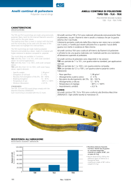
CRANES & COMPONENTS
INDICE
TABLE OF CONTENTS
POLYESTER WEB SLINGS AND ROUND SLINGS
FASCE E ANELLI CONTINUI DI POLIESTERE
SPECIFICATIONS - SAFETY INSTRUCTIONS
CARATTERISTICHE - NORME PER UN CORRETTO UTILIZZO
158
LOAD CAPACITY TABLE
PORTATE DELLE IMBRAGATURE
160
POLYESTER WEB SLINGS
FASCE DI POLIESTERE
2 LAYER WEB SLINGS - FPD type
FASCE A DOPPIO STRATO - Tipo FPD
161
2 LAYER WEB SLINGS - FPDR / FPDS type
FASCE A DOPPIO STRATO CON TRIANGOLI - Tipo FPDR / FPDS
162
4 LAYER WEB SLINGS - FPQ type
FASCE A 4 STRATI - Tipo FPQ
163
SINGLE LAYER WEB SLINGS - FPS type
FASCE BIANCHE A STRATO SEMPLICE - Tipo FPS
163
POLYESTER ROUND SLINGS
ANELLI CONTINUI DI POLIESTERE
164
ROUND SLINGS - TZE type - WLL from 1 t to 10 t
ANELLI CONTINUI - Tipo TZE - Portate da 1 t a 10 t
165
ROUND SLINGS - TLX type - WLL from 1 t to 150 t
ANELLI CONTINUI - Tipo TLX - Portate da 1 t a 150 t
166
ROUND SLINGS - TEX type - WLL from 12 t to 100 t
ANELLI CONTINUI - Tipo TEX - Portate da 12 t a 100 t
167
ULTRALIFT ROUND SLINGS - ULLD - ULCS type
ANELLI CONTINUI ULTRALIFT - Tipo ULLD - ULCS
168
ULTRALIFT ROUND SLINGS - ULLD type abrasion resistant
ANELLI CONTINUI ULTRALIFT - Tipo ULLD anti abrasione
170
ULTRALIFT ROUND SLINGS - ULCS - COIL SLING type cut resistant
ANELLI CONTINUI ULTRALIFT - Tipo ULCS - COIL SLING anti taglio
171
CORNER PROTECTIONS
PROTEZIONI
ULTRAPROTECT SLEEVES - UPLD type abrasion resistant
GUAINE ULTRAPROTECT - Tipo UPLD anti abrasione
172
ULTRAPROTECT SLEEVES - UPHD type cut resistant
GUAINE ULTRAPROTECT - Tipo UPHD anti taglio
173
ULTRAPROTECT CORNER PROTECTION - UPCP type cut resistant
CUSCINETTI PARASPIGOLI ULTRAPROTECT - Tipo UPCP anti taglio
174
ULTRAPROTECT SLING PROTECTION
GUAINE ULTRAPROTECT CON VELCRO DI CHIUSURA
175
STANDARD PROTECTIONS
PROTEZIONI TRADIZIONALI
176
MULTI-LEG POLYESTER SLINGS
BRACHE DI POLIESTERE A UNO O PIÙ BRACCI
178
LASHING SYSTEMS
SISTEMI DI ANCORAGGIO
EN 12195-2 LASHING SYSTEMS
SISTEMI DI ANCORAGGIO EN 12195-2
180
EN 12195-2 LASHING SYSTEMS - mm 25 and 35
SISTEMI DI ANCORAGGIO EN 12195-2 - Nastro mm 25 e 35
182
EN 12195-2 LASHING SYSTEMS - mm 50 and 75
SISTEMI DI ANCORAGGIO EN 12195-2 - Nastro mm 50 e 75
183
157
FASCE E ANELLI - PROTEZIONI - SISTEMI DI ANCORAGGIO
WEB SLINGS AND ROUND SLINGS - LASHING SYSTEMS
Fasce e anelli continui di poliestere
Protezioni - Sistemi di ancoraggio
Polyester web slings and round slings
Corner protections - Lashing systems
CRANES & COMPONENTS
Fasce e anelli continui di poliestere
CARATTERISTICHE
NORME PER UN CORRETTO UTILIZZO
SPECIFICATIONS - SAFETY INSTRUCTIONS
Polyester web slings and round slings
CARATTERISTICHE TECNICHE DEI NASTRI DI POLIESTERE
TECHNICAL SPECIFICATIONS OF THE POLYESTER SLINGS
The polyester fiber (PES) is a material with extraordinary
formability, easily workable and appropriate to provide solutions
in the case of special structural needs, thus allowing their
application in many areas. The main technical features:
- Excellent elasticity, toughness and resiliency;
- High modulus of elasticity;
- Elongation at WLL in the range of 3%; elongation at the
breakage in the range of 18%;
- Features unchanged wet or dry.
La fibra di poliestere (PES) è un materiale con straordinaria formabilità, facilmente
lavorabile e adatta a fornire soluzioni in caso di particolari esigenze strutturali,
permettendo quindi la loro applicazione in molti settori.
Le principali caratteristiche tecniche:
- Ottima elasticità, tenacità e resilienza;
- Elevato modulo di elasticità;
- Allungamento al carico massimo di lavoro 3% circa, allungamento a rottura 18% circa;
- Caratteristiche immutate allo stato asciutto e bagnato.
NORME DI RIFERIMENTO
STANDARDS
Web slings are manufactured according to EN 1492-1 while
round slings are in accordance with EN 1492-2.
According to Machinery Directive 2006/42/EC, the polyester
sling is encoded with the CE mark.
I riferimenti Europei per la costruzione delle brache di poliestere sono indicati nelle
norme armonizzate EN 1492-1 (brache piatte con asole) e EN 1492-2 (anelli continui).
In accordo alla Direttiva Macchine 2006/42/CE, la braca di poliestere viene
contrassegnata con il marchio CE.
PORTATA
WORKING LOAD LIMIT
The working load limit of a sling changes according to the type
of lift is determined on the basis of the modal factor, as shown
on page 160.
It is prohibited to perform lifting with angle β above 60° (figure 1).
La portata, o carico massimo di una braca varia in funzione della tipologia di
sollevamento e viene determinata in base al fattore modale, come illustrato a pag 160.
È proibito effettuare sollevamenti con angolo β superiore a 60° (Figura 1).
INFORMAZIONI DI SICUREZZA
SAFETY INSTRUCTIONS
European standards have established specific colours to identify
unambiguously the WLL of the round slings and web slings
(figure 2).
When the eyes of a web sling is inserted into the hook of the
crane, the angle must not exceed 20°, because the sewing
could tear (Figure 3).
The approximate formula provides that the length of the eye
of the loaded sling corresponds max to the width of the hook
multiplied 3,5 times: L= b x 3,5
An important aspect to which we must pay careful attention are
the sharp edges. For this reason, the radius of the angle r must
always be larger than the thickness d of the sling (figure 4).
If this is not possible, the slings of polyester must be equipped
with appropriate protections.
The polyester slings can be used in temperatures between -40 °C
and +100 °C (figure 5).
If they are being used in connection with chemicals, it is
absolutely necessary to contact the manufacturer to ensure
compatibility.
Colore
Portata
Viola/Violet
1,0 t
Verde/Green
2,0 t
Giallo/Yellow
3,0 t
Grigio/Grey
4,0 t
Rosso/Red
5,0 t
Marrone/Brown
6,0 t
Blu/Blue
8,0 t
Arancio/Orange
10,0 t
Colour
Fig. 1
158
Fig. 2
Le norme Europee hanno stabilito dei colori specifici per identificare in modo
inequivocabile la portata degli anelli continui e delle fasce per sollevamento (Figura 2).
Quando l’asola di una fascia viene inserita nel gancio della gru, l’angolo non deve
superare 20°, poiché la cucitura potrebbe strapparsi (Figura 3).
La formula approssimativa prevede che la lunghezza dell’asola sottocarico
corrisponda max alla larghezza del gancio moltiplicata 3,5 volte: L = b x 3,5
Un aspetto importante a cui bisogna prestare molta attenzione sono gli spigoli vivi.
Per questo motivo, il raggio dell’angolo r deve essere sempre maggiore dello spessore
d della braca di sollevamento (Figura 4).
Se questo non fosse possibile, le brache di poliestere devono obbligatoriamente
essere dotate di opportune protezioni.
Le brache di poliestere possono essere utilizzate in presenza di temperature comprese
tra -40 °C e +100 °C (Figura 5).
In presenza di prodotti chimici, è assolutamente necessario contattare il produttore
per verificare la compatibilità.
WLL
Fig. 3
Fig. 4
Fig. 5
CRANES & COMPONENTS
MARCATURA
MARKING
Ogni braca deve riportare le seguenti indicazioni:
- Identificazione del costruttore;
- Materiale del nastro (abbr. Poliestere: PES);
- Lunghezza nominale in metri;
- Carico massimo di esercizio;
- Codice di rintracciabilità;
- Marcatura CE;
- Le norme di riferimento.
Tali informazioni sono riportate in modo leggibile e
duraturo, tramite un’etichetta in materiale antistrappo
cucita all’interno di una delle due asole o sulla guaina
dell’anello.
Each sling must bear the following indications:
- Identification of the manufacturer;
- Material of the belt (abbr. Polyester: PES);
- Nominal length in meters;
- Maximum working load;
- Code of traceability;
- CE marking;
- The reference standards.
These information are reported in a readable and lasting way
through a label in tear-proof material sewn on the sling.
CONSIGLI D’USO
- Always inspect the sling before use, checking the data and the
instructions for use on the label.
- Never use slings damaged even partially.
- Avoid contact with sharp surfaces or abrasive: in this case, use
appropriate protections or edging.
- Check that the eyes of the web sling or the round sling are not
hooked to surfaces that can cause damage.
- Do not shorten the slings with knots, since the working load
would decrease dramatically.
- Do not crush the slings under the load and do not try to slip off
the sling if the load lays on the web.
- Not to scrape the sling on the ground during transport.
- Keep slings clean using cold water and then hang them to dry.
- The polyester decomposes in the sulphuric acid.
- Place the load so that it cannot overturn or fall during the lift.
Then place the sling so that the center of gravity is directly
above the load.
- When slings are used as a basket and work as a couple it
is recommended to use a lifting beam to hold the legs in a
vertical position.
- Verificare sempre l’integrità della braca prima di ogni utilizzo, controllando i dati
e le istruzioni d’uso riportate sull’etichetta.
- Non utilizzare mai brache danneggiate anche parzialmente.
- Evitare il contatto con superfici taglienti o abrasive: in questo caso utilizzare
opportune protezioni o paraspigoli.
- Verificare che l’asola della fascia o l’anello di poliestere non vengano agganciati
a superfici che possano danneggiarli.
- Non accorciare le brache annodandole, poiché la portata diminuirebbe enormemente.
- Non schiacciare le brache sotto il carico ne cercare di sfilarle se lo stesso
appoggia sul nastro.
- Non strisciare la braca sul terreno durante il trasporto.
- Conservare le brache pulite utilizzando acqua fredda e poi appenderle perché si
possano asciugare.
- Il poliestere si disintegra nell’acido solforico.
- Posizionare il carico in modo che non possa rovesciarsi o cadere durante
il sollevamento. Posizionare quindi la braca in modo che il baricentro sia
direttamente sopra il carico e quest’ultimo sia bilanciato.
- Quando le brache si utilizzano ad U e lavorano in coppia si raccomanda l’uso di
un bilancino per mantenere i bracci in posizione verticale.
RESISTENZA DELLE FIBRE AGLI AGENTI CHIMICI
CHEMICAL RESISTANCE INFORMATION
Materiale
Acidi
Acids
Alkalis
Ethers
Aldehyds
Alcohol
Oils
Oli
Solventi organici
Acqua di mare
Poliestere
SI / YES*
NO
NO
NO
SI / YES
SI / YES
SI / YES
SI / YES
Poliammide
NO
SI / YES
SI / YES
SI / YES
SI / YES
SI / YES
SI / YES
SI / YES
Polietiliene
SI / YES
SI / YES
SI / YES
SI / YES
SI / YES
SI / YES
SI / YES
SI / YES
Material
Polyester
Polyamide
Polyethylene
Alcali
Eteri
Aldeidi
Alcool
Organic solvents
Sea water
* Il poliestere si disintegra nell’acido solforico concentrato.
* Polyester decomposes when subject to concentrated sulfuric acid.
VERIFICHE PERIODICHE
PERIODIC CHECKS
The slings must be carefully inspected at the latest every three
months by a security officer, they should always be checked
before being used.
The web slings can no longer be used in the presence of cuts,
deformations or signs of deterioration, softening or stiffening of
the belt or loss of flexibility.
In the case of round slings discard the sling when the outside
sleeve is damaged.
Le brache devono essere ispezionate attentamente al più tardi ogni tre mesi da un
responsabile della sicurezza, fermo restando che vanno sempre controllate prima di
essere utilizzate.
Le brache non possono più essere utilizzate quando presentano tagli, anche di
piccole dimensioni, deformazioni o segni di deterioramento, rammollimento o
irrigidimento del nastro, o perdita di flessibilità. Nel caso di funi tonde ad anello,
scartare la braca non appena si lacera la guaina esterna.
159
FASCE E ANELLI - PROTEZIONI - SISTEMI DI ANCORAGGIO
WEB SLINGS AND ROUND SLINGS - LASHING SYSTEMS
WAY OF USE AND HANDLING
CRANES & COMPONENTS
PORTATA DELLE BRACHE DI POLIESTERE
WLL CAPACITY TABLE FOR WEBBING AND ROUND SLING
Fasce e anelli continui di poliestere
Polyester web slings and round slings
PORTATA DELLE IMBRAGATURE
LOAD CAPACITIES
Colori secondo
EN1492-1/2
Portata di 1 fascia o anello continuo
Colours according
to EN1492-1/2
Fattore di carico
Load factor
Portata di 2 fasce o anelli continui
WLL with 1 webbing sling or round sling
1
0,8
0°-7°
b
7°-45°
b
45°-60°
2
1,4
1
WLL with 2 webbing slings or round slings
b
7°-45°
b
45°-60°
b
7°-45°
b
45°-60°
b
7°-45°
b
45°-60°
0,7
0,5
1,4
1
1,12
0,8
Portata t
WLL t
1
0,8
2
1,4
1
0,7
0,5
1,4
1
1,12
0,8
2
1,6
4
2,8
2
1,4
1
2,8
2
2,24
1,6
3
2,4
6
4,2
3
2,1
1,5
4,2
3
3,36
2,4
4
3,2
8
5,6
4
2,8
2
5,6
4
4,48
3,2
5
4
10
7
5
3,5
2,5
7
5
5,6
4
6
4,8
12
8,4
6
4,2
3
8,4
5
6,72
4,8
8
6,4
16
11,2
8
5,6
4
11,2
8
8,96
5,4
10
8
20
14
10
7
5
14
10
11,2
8
12
9,6
24
16,8
12
8,4
6
16,8
12
13,44
9,6
15
12
30
21
15
10,5
7,5
21
15
16,8
12
20
16
40
28
20
14
10
28
20
22,4
16
25
20
50
35
25
17,5
12,5
35
25
28
20
30
24
60
42
30
21
15
42
30
33,6
24
40
32
80
56
40
28
20
56
40
44,8
32
50
40
100
70
50
35
25
70
50
56
40
60
48
120
84
60
42
30
84
60
67,2
48
70
56
140
98
70
49
35
98
70
78,4
56
80
64
160
112
80
56
40
112
80
89,6
64
90
72
180
126
90
63
45
126
90
100,8
72
100
80
200
140
100
70
50
140
100
112
80
110
88
220
154
110
77
55
154
110
123,2
88
115
92
230
161
115
80,5
57,5
161
115
128,8
92
•Le portate indicate si riferiscono a carichi simmetrici e bracci di uguale lunghezza.
•WLL is based on symmetrical load and legs of equal length.
160
CRANES & COMPONENTS
FASCE DI POLIESTERE
A DOPPIO STRATO TIPO FPD
Fasce e anelli continui di poliestere
POLYESTER 2 LAYER
WEB SLINGS FPD TYPE
Polyester web slings and round slings
CARATTERISTICHE
SPECIFICATIONS
The FPD web slings are made of 2 layers of polyester (PES)
and are available in 3 versions:
FPD with eyes
FPDR with triangles gr. 8 (male)
FPDS with triangles gr. 8 (male/female)
FEATURE
- Specific weight:
- Elongation at full load:
- Recovery from elongation of the 3%:
- Breaking elongation:
- Temperature of use:
- Moisture absorption:
1,38 g/cm3
3-4%
90 - 100%
12 - 18 %
- 40°C / + 100 °C
< 0,5 %
STANDARDS
FPD, FPDR and FPDS slings comply with the Machine
Directive 2006/42/EC.
Each sling is encoded with the CE mark.
Le fasce FPD sono realizzate in 2 strati di poliestere (PES) e sono
disponibili in 3 versioni:
FPD con asole;
FPDR con triangoli gr 8 (maschi);
FPDS con triangoli gr 8 (maschio/femmina).
CARATTERISTICHE
- Peso specifico: - Allungamento a pieno carico: - Recupero da allungamento del 3%:
- Allungamento a rottura: - Temperatura di impiego: - Assorbimento umidità: 1,38 g/cm3
3-4%
90 - 100%
12 - 18 %
- 40 °C / + 100 °C
< 0,5 %
NORME
Le brache FPD, FPDR e FPDS sono conformi alla Direttiva Macchine
2006/42/CE. Ogni braca riporta la marcatura CE.
Tipo FPD
Doppio strato
EN1492-1
Coefficiente di sicurezza: 7:1
Codice
Code
Colore
Colour
Portata
WLL
Larghezza
nastro
Larghezza
asola
Lunghezza
asola
Lunghezza
minima ca.
Webbing
width
2 layer
EN1492-1
Safety factor: 7:1
Eye width
Eye lenght
Minimum
lenght
Peso
1° metro
Weight
1st meter
Peso metro
successivo
Weight each
meter extra
t
mm
mm
mm
m
Kg
Kg
FPD050
1
50
30
250
1
0,22
0,2
FPD060
2
60
35
250
1
0,44
0,3
FPD090
3
90
50
300
1,5
0,71
0,5
FPD120
4
120
65
400
1,5
0,95
0,7
FPD150
5
150
80
400
2
1,2
0,9
FPD180
6
180
95
500
2
1,8
1,2
FPD240
8
240
125
500
3
2,3
1,5
FPD300
10
300
155
600
3
2,9
2
161
FASCE E ANELLI - PROTEZIONI - SISTEMI DI ANCORAGGIO
WEB SLINGS AND ROUND SLINGS - LASHING SYSTEMS
FPD type
CRANES & COMPONENTS
FASCE DI POLIESTERE
A DOPPIO STRATO TIPO FPDR - TIPO FPDS
con terminali metallici
Fasce di poliestere
Polyester web slings
POLYESTER 2 LAYER WEB SLINGS FPDR - FPDS TYPE
with triangles
Tipo FPDR - FPDS
FPDR - FPDS type
Tipo FPDR
Doppio strato
con 2 terminali DTR
Tipo FPDS
Doppio strato
con 1 terminale DTR
e 1 terminale DSTR
Codice
Code
Codice
Colore
Code
Portata
Colour
Larghezza
nastro
WLL
Webbing
width
FPDR
FPDR Type
2 layer
with 2 DTR triangles
FPDS Type
2 layer
with 1 DTR and 1 DSTR triangle
FPDS
Peso
1° metro
Peso
1° metro
FPDR
FPDS
Weight
1st meter
Weight
1st meter
Peso metro
successivo
Weight each
meter extra
t
mm
Kg
Kg
Kg
FPDR050
FPDS050
1
50
0,6
0,8
0,2
FPDR060
FPDS060
2
60
1,4
1,8
0,3
FPDR090
FPDS090
3
90
2,8
3,6
0,5
FPDR120
FPDS120
4
120
3,9
5,4
0,7
FPDR150
FPDS150
5
150
5,2
7,9
0,9
FPDR180
FPDS180
6
180
7,3
9,6
1,2
FPDR240
FPDS24O
8
240
13
17,5
1,5
FPDR300
FPDS300
10
300
19,7
25
2
•Tipo FPDR (con triangoli maschi)
•FPDR type (with male triangles)
•Tipo FPDS (con triangoli maschio / femmina)
•FPDS type (with male / female triangles)
Terminali metallici DTR - DSTR
DTR - DSTR triangles
Codice
Codice
Portata
Larghezza nastro
DTR
DSTR
t
S
mm
D
mm
D1
mm
DTR010
DSTR010
1
50
45
DTR020
DSTR020
2
60
30
DTR030
DSTR030
3
90-100
DTR040
DSTR040
4
DTR050
DSTR050
DTR060
DSTR060
DTR080
DTR100
Code
Tipo DTR
DTR Type
162
Code
WLL
Dimensioni
Webbing width
Peso
Dimensions
Peso
Weight
Weight
E
mm
H
mm
H1
mm
P
mm
Q
mm
DTR
Kg
DSTR
Kg
50
70
60
100
25
12
0,2
0,4
40
100
80
146
40
16
0,5
1
60
70
146
120
205
55
20
1,1
2
120
60
80
179
130
218
55
23
1,6
3,1
5
150
90
90
222
180
300
80
26
2,2
5
6
180
90
90
262
180
284
80
28
3
5,4
DSTR080
8
240
100
120
344
200
332
90
32
5,8
10,2
DSTR100
10
300
100
120
400
250
385
100
35
7,9
13,8
1t
≥2t
Tipo DSTR
DSTR Type
CRANES & COMPONENTS
FASCE DI POLIESTERE
POLYESTER WEB SLINGS
Fasce di poliestere
Polyester web slings
FASCE DI POLIESTERE A 4 STRATI TIPO FPQ
POLYESTER 4 LAYER WEB SLINGS FPQ TYPE
The FPQ slings are made with 4 layers of polyester (PES)
and available with WLL from 2t to 40t (straight load).
Le brache FPQ sono realizzate in 4 strati di poliestere (PES) e sono
disponibili con portate da 2t a 40t (tiro diretto).
STANDARDS
The FPQ slings comply with the Machine Directive
2006/42/EC. Each sling is encoded with the CE mark.
NORME
Le brache a 4 strati FPQ sono conformi alla Direttiva Macchine
2006/42/CE. Ogni braca riporta la marcatura CE.
Codice
Portata
Code
Larghezza Larghezza Lunghezza
nastro
asola
asola
WLL
4 layer
Safety factor: 7:1
t
t
0° - 45°
45° - 60°
t
t
t
Webbing
width
Eye width
Eye lenght
Peso
4 metri
Weight
4 metres
Peso metro
successivo
mm
mm
mm
Kg
Kg
Weight each
meter extra
FPQ060
4
3,2
8
5,6
4
60
40
250
2,9
0,7
FPQ090
6
4,8
12
8,4
6
90
50
300
4,6
1,1
FPQ120
8
6,4
16
11,2
8
120
60
400
6,3
1,5
FPQ150
10
8
20
14
10
150
80
650
7,7
1,9
2,4
FPQ180
12
9,6
24
16,8
12
180-200
95-105
700
10,1
FPQ240
16
12,8
32
22,4
16
240
125
850
12,4
3
FPQ300
20
16
40
28
20
300
160
1100
16,3
3,9
FPQ300S
25
20
50
35
25
300
160
1200
19,6
4,7
FPQ500
30
24
60
42
30
500
260
1500
26,5
6,4
FPQ600
40
32
80
56
40
600
310
1500
41
9,8
FASCE E ANELLI - PROTEZIONI - SISTEMI DI ANCORAGGIO
WEB SLINGS AND ROUND SLINGS - LASHING SYSTEMS
4 strati
Coefficiente di sicurezza: 7:1
FASCE BIANCHE DI POLIESTERE A STRATO SEMPLICE TIPO FPS
POLYESTER SINGLE LAYER WEB SLINGS WHITE COLOUR FPS TYPE
The FPS slings are made of a high quality white colour
polyester.
Le fasce FPS sono realizzate in poliestere (PES) di alta qualità di colore
bianco.
STANDARDS
The FPS white slings comply with Machine Directive
2006/42/EC.
Each sling is encoded with the CE mark.
NORME
Le brache piatte bianche FPS sono conformi alla Direttiva Macchine
2006/42/CE.
Ogni braca riporta la marcatura CE.
A strato semplice
Coefficiente di sicurezza: 7:1
Codice
Portata
Code
WLL
Larghezza
nastro
Lunghezza
asola
mm
Webbing
width
Single layer
Safety factor: 7:1
0° - 45°
Eye lenght
45° - 60°
t
t
t
t
t
mm
FPS050
0,5
0,4
1
0,7
0,5
50
250
FPS060
1
0,8
2
1,4
1
60
250
FPS075
1,25
1
2,5
1,75
1,25
75
250
FPS100
1,7
1,35
3,4
2,35
1,7
100
300
FPS150
2,5
2
5
3,5
2,5
150
400
FPS180
3
2,4
6
4,2
3
180
500
FPS300
5
4
10
7
5
300
600
163
CRANES & COMPONENTS
ANELLI CONTINUI DI POLIESTERE
TIPO TZE - TLX - TEX
Anelli continui di poliestere
POLYESTER ROUND SLINGS
TZE - TLX - TEX TYPE
Polyester round slings
CARATTERISTICHE
SPECIFICATIONS
The TZE and TLX round slings are made using exclusively
polyester fibers, both for the internal filaments wound a
skein and for the outer sleeve.
The loading inner fiber is never in contact with the load,
and the round sling can be used until the wear of the
sleeve does not highlight the internal fibers.
The TEX round slings are made inside by polyester
filaments and outside by a sleeve made of a material with
higher resistance to abrasion compared to polyester.
The round slings are available in 3 versions:
TZE with WLL from 1 t to 10 t, with outer standard
sleeve for normal applications;
TLX with WLL from 1 t to 100 t, with outer compact
sleeve;
TEX with WLL from 12 t to 100 t, with outer heavy
sleeve against abrasion.
-
-
-
-
-
-
Specific weight:
Elongation at full load:
Recovery from elongation of the 3%:
Breaking elongation
Temperature of use:
Moisture Absorption:
1,38 g/cm3
3-4%
90 - 100%
12 - 18 %
- 40°C / + 100°C
< 0,5 %
STANDARDS
The TZE, TLX and TEX round slings comply with the
Machine Directive 2006/42/EC.
Each round sling is encoded with the CE mark.
Gli anelli continui TZE e TLX sono realizzati utilizzando esclusivamente fibre
di poliestere, sia per i filamenti interni avvolti a matassa che per la guaina
esterna che li racchiude.
L’elemento portante costituito dalla fibra interna non viene mai a contatto
con il carico, e l’anello può essere utilizzato fino a quando l’usura della
guaina non mette in evidenza le fibre interne.
Gli anelli continui TEX sono costituiti all’interno da filamenti di poliestere
e all’esterno da una guaina realizzata con materiale avente una resistenza
all’abrasione superiore al poliestere.
Gli anelli continui di poliestere sono disponibili in tre versioni:
TZE con portate da 1 t a 10 t, con guaina esterna standard, per applicazioni
normali;
TLX con portate da 1 t a 100 t, con guaina esterna compatta;
TEX con portate da 12 t a 100 t, con guaina esterna pesante contro
l’abrasione.
-
-
-
-
-
-
Peso specifico:
Allungamento a pieno carico:
Recupero da allungamento del 3%:
Allungamento a rottura:
Temperatura di impiego:
Assorbimento umidità:
1,38 g/cm3
3-4%
90 - 100 %
12 - 18 %
- 40°C / + 100°C
< 0,5 %
NORME
Gli anelli continui TZE, TLX e TEX sono conformi alla Direttiva Macchine
2006/42/CE. Ogni anello riporta la marcatura CE.
RESISTENZA ALL’ABRASIONE
RESISTANCE AGAINST
ABRASION
RESISTENZA
ALL’ABRASIONE
RESISTANCE AGAINST ABRASION
•Risultato ottenuto facendo
scorrere i diversi tipi di guaina
su una base esagonale,
creando un angolo di 90°, con
un peso di 2 kg.
Numero di cicli
Number of cycles
120.000
100.000
80.000
•Result obtained by sliding the
different types of sleeve on a
hexagonal base,
creating an angle of 90° with a
weight of 2 kg.
60.000
40.000
20.000
0
164
TZE
TLX
TEX
CRANES & COMPONENTS
ANELLI CONTINUI
DI POLIESTERE TIPO TZE
portate da 1 t a 10 t
Anelli continui di poliestere
Polyester round slings
POLYESTER ROUND SLINGS
TZE TYPE
WLL from 1 to 10 t
CARATTERISTICHE
SPECIFICATIONS
Round slings with good quality sleeve, for standard
application.
Anelli continui di poliestere estremamente flessibili con guaina esterna di
buona qualità, per applicazioni normali.
RANGE
Tze round slings are available with WLL from 1 t to 10 t.
PORTATE
Gli anelli continui TZE sono disponibili con portate da 1 t a 10 t.
STANDARDS
TZE round slings comply with Machine Directive 2006/42/CE.
Each round sling is encoded with the CE mark.
NORME
Gli anelli continui TZE sono prodotti in accordo alla Direttiva Macchine
2006/42/CE.
Ogni braca riporta la marcatura CE.
Tipo TZE
TZE type
Codice
Code
Colore
0°-7°
Colour
b
7°-45°
b
45°-60°
EN 1492-2
Safety factor: 7:1
Fattore di carico
Load factor
1
2
1,4
Diametro
anima
interna
Sleeve width
Peso anello con
lunghezza
effettiva 1m
Lunghezza
minima
Inner core
diameter
Larghezza
guaina
esterna
mm
mm
Kg
m
Round sling
weight effective
lenght 1 m
Minimum
lenght
1
Portata (t)
WLL (t)
TZE01
1
2
1,4
1
12
47
0,2
0,5
TZE02
2
4
2,8
2
18
48
0,35
0,5
TZE03
3
6
4,2
3
20
54
0,5
0,5
TZE04
4
8
5,6
4
22
70
0,65
0,75
TZE05
5
10
7
5
28
72
0,8
0,75
TZE06
6
12
8,4
5
30
74
1
1,5
TZE08
8
16
11,2
8
32
90
1,35
1,5
TZE10
10
20
14
10
35
91
1,65
2
FASCE E ANELLI - PROTEZIONI - SISTEMI DI ANCORAGGIO
WEB SLINGS AND ROUND SLINGS - LASHING SYSTEMS
EN 1492-2
Coefficiente di sicurezza: 7:1
165
CRANES & COMPONENTS
ANELLI CONTINUI
DI POLIESTERE TIPO TLX
portate da 1 t a 150 t
Anelli continui di poliestere
Polyester round slings
POLYESTER ROUND SLINGS
TLX TYPE
WLL from 1 to 150 t
CARATTERISTICHE
SPECIFICATION
TLX is made with an outer sleeve with higher strength
properties compared to normal round slings. In addition,
the compact structure and stable of the sleeve favors a
better adhesion of the round sling to the hook of the
crane and the load to be lifted.
TLX è realizzato con una guaina esterna avente caratteristiche di resistenza
superiori rispetto agli anelli continui normali.
Inoltre la struttura compatta e stabile della guaina favorisce una migliore
adesione dell’anello al gancio della gru e al carico da sollevare.
RANGE
TLX round slings are available up to 100 t WLL.
PORTATE
Gli anelli continui TLX sono prodotti con portate fino a 100 t in tiro diretto.
STANDARDS
The TLX round slings comply with the Machine Directive
2006/42/EC. Each round sling is encoded with the CE mark.
NORME
Gli anelli continui TLX sono prodotti in accordo alla Direttiva Macchine
2006/42/CE. Ogni braca riporta la marcatura CE.
Tipo TLX
TLX type
EN 1492-2
Coefficiente di sicurezza: 7:1
Codice
Colore
Code
b
7°-45°
0°-7°
Colour
b
45°-60°
Larghezza
guaina
Sleeve width
EN 1492-2
Safety factor: 7:1
Round sling
weight effective
lenght 1 m
Fattore di carico
Load factor
1
2
1,4
1
Portata (t)
mm
Kg
TLX010
1
2
1,4
1
41
0,3
TLX020
2
4
2,8
2
50
0,5
TLX030
3
6
4,2
3
54
0,6
TLX040
4
8
5,6
4
68
0,8
TLX050
5
10
7
5
74
1
TLX060
6
12
8,4
5
78
1,2
TLX080
8
16
11,2
8
90
1,6
TLX100
10
20
14
10
96
1,9
TLX120
12
24
16,8
12
110
2,6
TLX150
15
30
21
15
110
3,4
TLX200
20
40
28
20
132
4,4
TLX250
25
50
35
25
132
5,6
TLX300
30
60
42
30
160
6,2
TLX350
35
70
49
35
160
7,3
TLX400
40
80
56
40
160
8
TLX500
50
100
70
50
180
11,5
TLX600
60
120
84
60
220
13,8
TLX700
70
140
98
70
220
15,7
TLX800
80
160
112
80
320
18,2
TLX900
90
180
126
90
320
20,2
TLX1000
100
200
140
100
320
22,3
TLX1000
115
230
160
115
320
29
WLL (t)
Disponibili su richiesta
TLX1250 (125 t)
e TLX1500 (150 t)
Available on demand
TLX1250 (125 t)
and TLX1500 (150 t)
166
Peso anello
con lunghezza
effettiva 1m
CRANES & COMPONENTS
ANELLI CONTINUI DI POLIESTERE
CON GUAINA MOLTO PESANTE TIPO TEX
portate da 12 t a 100 t
Anelli continui di poliestere
Polyester round slings
POLYESTER ROUND SLINGS
WITH HEAVY SLEEVE TEX TYPE
WLL from 12 to 100 t
CARATTERISTICHE
SPECIFICATION
The TEX round sling are inside made by polyester filaments
and outside by a high resistance to abrasion sleeve, up to
five times higher than the standard polyester round slings
RANGE
The TEX round slings are available with WLL from 12 t to
100 t.
STANDARDS
The TEX round slings comply with the Machine Directive
2006/42/EC. Each round sling is encoded with the CE mark.
Gli anelli continui TEX sono costituiti all’interno da filamenti di poliestere
e all’esterno da una guaina realizzata con materiale avente alta resistenza
all’abrasione, fino a cinque volte superiore rispetto agli anelli di poliestere
standard in commercio.
PORTATE
Gli anelli continui TEX sono disponibili con portate fino da 12 t a 100 t.
NORME
Gli anelli continui TEX sono prodotti in accordo alla Direttiva Macchine
2006/42/CE. Ogni braca riporta la marcatura CE.
Tipo TEX
TEX type
Codice
Colore
Code
b
7°-45°
0°-7°
Colour
b
45°-60°
Larghezza
guaina
Sleeve width
EN 1492-2
Safety factor: 7:1
Peso anello
con lunghezza
effettiva 1m
Round sling
weight effective
lenght 1 m
Fattore di carico
Load factor
1
2
1,4
1
Portata (t)
mm
Kg
TEX120
12
24
16,8
12
110
2,8
TEX150
15
30
21
15
110
3,6
TEX200
20
40
28
20
135
4,5
TEX250
25
50
35
25
135
5,8
TEX300
30
60
42
30
160
6,3
TEX350
35
70
49
35
160
7,4
TEX400
40
80
56
40
160
8,2
TEX500
50
100
70
50
180
10,7
TEX600
60
120
84
60
220
12,9
TEX700
70
140
98
70
220
14,8
TEX800
80
160
112
80
300
18,4
TEX900
90
180
126
90
300
20,5
TEX1000
100
200
140
100
300
22,5
WLL (t)
FASCE E ANELLI - PROTEZIONI - SISTEMI DI ANCORAGGIO
WEB SLINGS AND ROUND SLINGS - LASHING SYSTEMS
EN 1492-2
Coefficiente di sicurezza: 7:1
167
CRANES & COMPONENTS
Anelli continui ULTRALIFT
ULTRALIFT round slings
ANELLI CONTINUI ULTRALIFT
TIPO ULLD - ULCS
ULTRALIFT ROUND SLINGS
ULLD - ULCS TYPE
CARATTERISTICHE
SPECIFICATION
The ULLD and ULCS round slings are 100% Dyneema®
made and are indicated for repetitive and difficult lifts,
up to 200 t working load. They are very light, about 2,5
times more compared to polyester and 8 times more of
the corresponding slings of steel and have a very low
coefficient of elongation (0,5%).
Gli anelli continui ULLD e ULCS sono realizzati 100% di fibra Dyneema® e
sono indicati per sollevamenti ripetitivi e difficili, fino a 200 t di portata.
Sono molto leggeri, circa 2,5 volte più del poliestere e 8 volte più delle
corrispondenti brache di acciaio e hanno un bassissimo coefficiente di
allungamento (0,5%).
Dyneema® is a high resistance polyethylene yarn
(HPPE) able to offer the maximum strength with the
lowest possible weight. Dyneema® is a high resistance
polyethylene fiber (HPPE) which is able to offer the
maximum strength with the lowest possible weight. For
example, a ULLD 20 t 10 m length round sling weighs
approximately 18 Kg, while the polyester TLX type with
identical characteristics, weighs about 42 Kg. Dyneema®
offers a high resistance to heavy abrasion, for example by
concrete or to cut from coils. Dyneema® floats in the water
and it is resistant to moisture, UV rays, acids and alkalines.
Dyneema® è una fibra di polietilene ad alta resistenza (HPPE) in grado di
offrire la massima resistenza con il minor peso possibile.
Per esempio, un anello tipo ULLD in Dyneema da 20 ton di portata e 10
m di lunghezza effettiva pesa circa 18 Kg, mentre il tipo TLX di poliestere,
avente uguali caratteristiche, pesa circa 42 Kg.
Dyneema® offre un’alta resistenza all’abrasione molto pesante, per esempio
da cemento o al taglio da coil.
Dyneema® galleggia nell’acqua e resiste all’umidità, ai raggi UV, agli acidi e
agli alcali.
- Specific weight: 0.97 g/cm3
- Elongation at full load:
0.5 %
- Temperature of use: -50°C / +60°C;
- Resistance to chemical agents: good resistance
to acids, alkalis,
and micro-organisms;
- Moisture absorption:
0 %;
- Minimum ratio hooking pin ring ULLD or ULCS: 3:1
NORMS
The Ultralift round slings comply with the Machine
Directive 2006/42/EC. Each round sling is encoded with
the CE mark. Every Ultralift round sling is tested at
double nominal WLL before delivery.
168
- Peso specifico: 0,97 g/cm3
- Allungamento a pieno carico: 0,5 %
- Temperatura di impiego: -50°C / +60°C;
- Resistenza agli agenti chimici: Buona resistenza agli acidi,
alcali e micro organismi;
- Assorbimento umidità:
0 %;
- Rapporto minimo perno di aggancio anello ULLD o ULCS: 3:1
NORME
Gli anelli Ultralift sono conformi alla Direttiva Macchine 2006/42/CE.
Ogni braca riporta la marcatura CE.
Ogni anello continuo Ultralift viene provato al doppio della portata prima
della consegna.
CRANES & COMPONENTS
ANELLI CONTINUI ULTRALIFT
TIPO ULLD - ULCS
Anelli continui ULTRALIFT
ULTRALIFT ROUND SLINGS
ULLD - ULCS TYPE
ULTRALIFT round slings
TEST DI FATICA - AL 50% DEL CARICO MINIMO DI ROTTURA
FATIQUE TEST - AT 50% OF MINIMUM BREAKING LOAD
Numero cicli x 1000
Number of cycles x 1000
12000
10000
10000
8000
6000
4000
2000
0
1000
Ultralift
Fibre aramidiche
Aramid fibers
6.5
100
2.5
1,5
Acciaio
Steel
Poliestere
(PES)
Polietilene
(PA)
Polipropilene
(PP)
COMPARAZIONE PESI DELLE BRACHE
COMPARISON IN WEIGHT
Braca di fune
Wire rope sling
500 kg
400 kg
Anello di fune
Grommet
300 kg
200 kg
Braca di poliestere
Poliester sling
100 kg
ULTRALIFT
15 t 20 t
40 t
60 t
80 t
120 t
FASCE E ANELLI - PROTEZIONI - SISTEMI DI ANCORAGGIO
WEB SLINGS AND ROUND SLINGS - LASHING SYSTEMS
Peso proprio braca
Sling weight
600 kg
Portata braca
Sling WLL
169
CRANES & COMPONENTS
ANELLI CONTINUI ULTRALIFT
TIPO ULLD
anti abrasione
Anelli continui ULTRALIFT
ULTRALIFT round slings
ULTRALIFT ROUND SLINGS
ULLD TYPE
abrasion resistant
CARATTERISTICHE
SPECIFICATION
The ULLD Ultralift round slings are 100% Dyneema®
made, both the inner soul and the outer sleeve.
ULLD are indicated for repetitive and precise lifting,
thanks to the very light weight (2,5 times less than
polyester and 8-10 times less the wire rope slings) and to
the low coefficient of elongation (0,5%).
The outer sleeve is also very high resistance to abrasion.
Gli anelli continui Ultralift ULLD sono realizzati al 100% di fibra Dyneema®,
sia i filamenti che costituiscono l’anima portante, che la guaina esterna.
ULLD sono indicati per sollevamenti ripetitivi e precisi, grazie al peso
ridottissimo (2,5 volte meno del poliestere e 8-10 volte meno delle brache
di fune d’acciaio) e al basso coefficiente di allungamento (0,5%).
La guaina esterna presenta inoltre una altissima resistenza all’abrasione.
Tipo ULLD
ULLD type
Codice
0°-7°
Code
b
7°-45°
b
45°-60°
Larghezza
guaina esterna
Outer
sleeve width
Fattore di carico
Load factor
1
2
1,4
Peso anello
con lunghezza
effettiva 3 m
Peso m
effettivo
addizionale
Round sling weight
effective lenght 3 m
Extra m weight
Kg
Kg
1
Portata (t)
mm
WLL (t)
ULLD020
2
4
2,8
2
65/55
1,7
0,5
ULLD030
3
6
4,2
3
65/55
1,8
0,6
0,7
ULLD040
4
8
5,6
4
75/65
2,2
ULLD050
5
10
7
5
75/65
2,3
0,7
ULLD060
6
12
8,4
6
90/65
2,5
0,8
ULLD080
8
16
11,2
8
90/75
3,4
1,1
ULLD100
10
20
14
10
115/90
3,9
1,2
ULLD150
15
30
21
15
98
4,9
1,5
ULLD200
20
40
28
20
98
5,7
1,6
ULLD250
25
50
35
25
115
7,3
1,8
ULLD300
30
60
42
30
125
8
2,5
ULLD400
40
80
56
40
133
9,6
2,9
ULLD500
50
100
70
50
183
15,4
4,6
ULLD600
60
120
84
60
183
16,6
5,1
ULLD700
70
140
98
70
183
20,4
6,3
ULLD800
80
160
112
80
213
22,3
6,9
ULLD900
90
180
126
90
228
24,2
7,5
ULLD1000
100
200
140
100
228
32,6
8,8
ULLD1200
120
240
168
120
283
33,6
10,3
ULLD1400
140
280
196
140
283
41,2
11,7
ULLD1600
160
320
224
160
343
46,9
13,6
ULLD1800
180
360
252
180
343
51
15
ULLD2000
200
400
280
200
343
55,1
16,4
170
CRANES & COMPONENTS
ANELLI CONTINUI ULTRALIFT
TIPO ULCS - COIL SLING
anti taglio
Anelli continui ULTRALIFT
ULTRALIFT round slings
ULTRALIFT ROUND SLINGS
ULCS - COIL SLING TYPE
cut resistant
CARATTERISTICHE
SPECIFICATION
The Ultralift ULCS Coil Sling have been designed for the
lifting of coils or loads with sharp edges.
Entirely made of Dyneema®, with the addition of the
UPHD protection on both arms, ULCS coil slings have
an incredible resistance to cutting and do not require
additional protections (wedges, polyurethane, etc.).
The ULCS Coil Sling are indicated for repetitive lifts thanks
to the lightest weight (a sling ULCS working load 20 t with
effective length 5 m, weighs about 13 kg, while a steel
grommet with same characteristics weighs about 100 kg).
The life of the outer sleeve is very long, and when after
many operations the wear indicator (2 red strips) should
show the usage limits, it can be easily replaced by reusing
the same sling.
Gli anelli continui Ultralift ULCS Coil Sling sono stati concepiti per il
sollevamento di coils o carichi con spigoli taglienti.
Realizzati interamente di fibra Dyneema®, con l’aggiunta della protezione
UPHD su entrambi i bracci, hanno un’incredibile resistenza al taglio e non
richiedono ulteriori protezioni (cunei, poliuretano, ecc.).
Le brache ULCS Coil Sling sono indicate per sollevamenti ripetitivi grazie
al peso ridottissimo (una braca ULCS, 20 t di portata con lunghezza
effettiva 5 m, pesa circa 13 kg mentre il classico anello di fune d’acciaio
con pari caratteristiche pesa circa 100 kg).
La durata della guaina esterna è elevatissima e, quando dopo
moltissime operazioni l’indicatore di usura (2 strisce di filato rosse)
dovesse evidenziarne i limiti di utilizzo, può essere facilmente sostituita
riutilizzando lo stesso anello.
Tipo ULCS
ULCS type
0°-7°
Code
b
7°-45°
b
45°-60°
Larghezza
guaina esterna
Outer
sleeve width
Fattore di carico
Load factor
1
2
1,4
Peso anello
con lunghezza
effettiva 3 m
Peso m
effettivo
addizionale
Round sling weight
effective lenght 3 m
Extra m weight
Kg
Kg
1
Portata (t)
mm
WLL (t)
ULCS100
10
20
14
10
125
6
2
ULCS150
15
30
21
15
155
7,4
2,5
2,8
ULCS200
20
40
28
20
155
8,2
ULCS250
25
50
35
25
185
10,3
3,4
ULCS300
30
60
42
30
185
11
3,7
Tipo/type ULLD
FASCE E ANELLI - PROTEZIONI - SISTEMI DI ANCORAGGIO
WEB SLINGS AND ROUND SLINGS - LASHING SYSTEMS
Codice
Tipo/type ULCS
171
CRANES & COMPONENTS
GUAINE ULTRAPROTECT TIPO UPLD
anti abrasione
Protezioni
ULTRAPROTECT SLEEVES UPLD TYPE
abrasion resistant
Corner protections
CARATTERISTICHE
SPECIFICATION
Tipo
Type
Larghezza
esterna
Larghezza
interna
mm
Outer
width
Inner
width
Idonee
per fasce D.S.
Suitable for
2 layer web slings
Idonee
per anelli continui
Idonee
per catene
mm
mm
t
mm
1-2-3
Suitable
for round slings
Suitable
for chains
UPLD 65
73
65
50
UPLD 75
83
75
60
4
6-7
UPLD 90
98
90
-
5-6
8 - 10
UPLD 115
123
115
90
8 - 10
UPLD 125
133
125
-
-
UPLD 145
153
145
120
12 - 15
13
UPLD 175
183
175
150
20 - 25
16
UPLD 205
213
205
180
-
-
UPLD 220
228
220
-
30 - 35 - 40
20 - 22
UPLD 260
268
260
-
-
UPLD 275
283
275
240
50 - 60
UPLD 335
343
335
300
70
172
26 - 32
CRANES & COMPONENTS
GUAINE ULTRAPROTECT TIPO UPHD
anti taglio
Protezioni
ULTRAPROTECT SLEEVES UPHD TYPE
cut resistant
Corner protections
CARATTERISTICHE
SPECIFICATION
Tipo
Type
Larghezza
esterna
Larghezza
interna
mm
Outer
width
Inner
width
Idonee
per fasce D.S.
Suitable
for 2 layer web slings
Idonee
per anelli continui*
Idonee
per catene
mm
mm
t
mm
1-2-3
Suitable
for round slings*
Suitable
for chains
UPHD 65
75
65
50
UPHD 75
85
75
60
4
UPHD 90
100
90
-
5-6
6-7
UPHD 115
125
115
90
8 - 10
8 - 10
UPHD 125
135
125
-
-
UPHD 145
155
145
120
12 - 15
13
UPHD 175
185
175
150
20 - 25
16
UPHD 205
215
205
180
-
-
UPHD 220
230
220
-
30 - 35 - 40
20 - 22
UPHD 260
270
260
-
-
UPHD 275
285
275
240
50 - 60
26
UPHD 335
345
335
300
70
32
FASCE E ANELLI - PROTEZIONI - SISTEMI DI ANCORAGGIO
WEB SLINGS AND ROUND SLINGS - LASHING SYSTEMS
* Entrambi i bracci dell’anello inseriti nella guaina.
* Both round sling legs in the sleeve.
173
CRANES & COMPONENTS
CUSCINETTI PARASPIGOLI
ULTRAPROTECT TIPO UPCP
anti taglio
Protezioni
Corner protections
ULTRAPROTECT CORNER PROTECTION UPCP TYPE
cut resistant
CARATTERISTICHE
SPECIFICATION
UPCP is a new protection against sharp edges unique in its
kind. Made of 100% Dyneema®, extremely resistant to cut,
and adapts perfectly to the shape of the corner.
-
-
-
-
-
-
-
-
-
Protection against abrasion and the sharp edges
Suitable for web slings, round slings, ropes and chains
Made 100% Dyneema®
Extremely lightweight compared to traditional
protections
Perfectly adhere to the shape of the loads to be lifted
Wear indicators
Velcro of quality for a secure fit
Available in various sizes
Suitable for many operations
UPCP è una nuova protezione contro gli spigoli vivi unica nel suo genere.
Realizzata al 100% in fibra Dyneema®, è estremamente resistente al
taglio, e si adatta perfettamente alla forma dello spigolo.
-
-
-
-
-
-
-
-
-
Protezione contro l’abrasione e gli spigoli vivi
Idonei per fasce, anelli continui, funi e catene
Realizzati 100% in Dyneema®
Estremamente leggeri rispetto alle protezioni tradizionali
Aderiscono perfettamente alla forma dei carichi da sollevare
Indicatori di usura all’interno
Velcro di qualità per un fissaggio sicuro
Disponibili in varie dimensioni
Idonei per moltissime operazioni
Tipo UPCP
UPCP type
Codice
Code
Idonei per anelli continui
Suitable for round slings
t
Idonei per fasce d. s.
Suitable for 2 layers web slings
Tipo
Dimensioni
Type
Dimensions
A
mm
mm
B
mm
C
mm
UPCP 65/200
1-2-3
50
1
65
200
50
UPCP 75/250
4-5-6
60
1
75
250
50
UPCP 85/300
75
1
85
300
50
UPCP 100/300
90
1
100
300
50
UPCP 125/300
8
100 - 120
1
125
300
50
UPCP 135/300
10 - 12
125
1
135
300
50
50
UPCP 155/500
15
150
2
155
500
UPCP 185/600
20 -25
180
2
185
600
75
UPCP 215/600
30
200
2
215
600
75
UPCP 230/800
35 - 40
200
2
230
800
75
UPCP 285/800
45 - 55
250
2
285
800
100
UPCP 345/800
60 - 65
300
2
345
800
100
UPCP 370/800
70 - 75
2
370
800
100
UPCP 430/800
80
2
430
800
100
UPCP 460/800
85
2
460
800
100
UPCP 540/800
90 - 100
2
540
800
100
UPCP 690/800
125
2
690
800
100
Tipo 1
Type 1
Tipo 2
Type 2
174
CRANES & COMPONENTS
Corner protections
GUAINE ULTRAPROTECT
CON VELCRO DI CHIUSURA
TIPO UPSPLD anti abrasione
TIPO UPSPHD anti taglio
CARATTERISTICHE
ULTRAPROTECT SLING PROTECTION
UPSPLD abrasion resistant TYPE
UPSPHD cut resistant TYPE
Protezioni
SPECIFICATION
The Ultraprotect UPSPLD and UPSPHD sling protections
made in Dyneema® are suitable for protecting the
round slings and the web slings against strong abrasion
(UPSPLD) or the sharp corners (UPSPHD).
Thanks to the velcro closure, these protections are
extremely practical, easily positioned and adaptable to
round slings (1 or 2 legs), web slings, chains or ropes.
They are extremely lighter and more flexible protection
compared to traditional ones, with the advantage to
adapt perfectly to the surface of the load.
Suitable for many operations, equipped inside with wear
indicators.
Available up to 10 m in length.
Le guaine Ultraprotect UPSPLD e UPSPHD
realizzate in fibra Dyneema® sono idonee
per proteggere gli anelli continui e le fasce di
poliestere contro una forte abrasione (UPSPLD) o
gli spigoli vivi (UPSPHD).
Grazie alla chiusura con velcro, queste protezioni
sono estremamente pratiche, facilmente
posizionabili e adattabili ad anelli continui (1 o 2
bracci), fasce piatte, catene o funi.
Sono estremamente più leggere e flessibili delle
protezioni tradizionali, con il vantaggio di adattarsi
perfettamente alla superficie del carico.
Idonee per moltissime operazioni, sono provviste
di indicatori di usura all’interno.
Disponibili fino a 10 m di lunghezza.
Tipo UPSPLD - Anti abrasione
Tipo
Type
Idonei per fasce
Suitable for web slings
Idonei per anelli continui
Suitable for round slings
Larghezza interna
min / max
Diametro interno max
mm
mm
FASCE E ANELLI - PROTEZIONI - SISTEMI DI ANCORAGGIO
WEB SLINGS AND ROUND SLINGS - LASHING SYSTEMS
UPSPLD type - Abrasion resistant
Max inner diameter
Inside width
min / max
mm
t
UPSPLD - 75
50
1-2
50 - 60
35
UPSPLD - 90
60
3
60 - 65
38
UPSPLD - 115
90
4-5-6-8
80 - 100
50
UPSPLD - 145
100
10
90 - 115
57
UPSPLD - 175
120 - 150
10 - 12 - 15 - 20
120 - 150
76
UPSPLD - 205
-
25 - 30 - 35 - 40
155 - 180
98
UPSPLD - 220
180
50
165 - 190
105
UPSPLD - 275
240
60
215 - 250
136
UPSPLD - 335
300
70 - 80
285 - 305
181
Idonei per fasce
Idonei per anelli continui
Larghezza interna
min / max
Diametro interno max
mm
mm
Tipo UPSPHD - Anti taglio
UPSPHD type - Cut resistant
Tipo
Type
Suitable for web slings
Suitable for round slings
Max inner diameter
Inside width
min / max
mm
t
UPSPHD - 90
60
1-2-3
60 - 70
38
UPSPHD - 115
90
4-5-6-8
75 - 95
47
UPSPHD - 145
100
10
95 - 105
57
UPSPHD - 175
120
10 - 12 - 15 - 20
120 - 140
76
UPSPHD - 205
150
25 - 30 - 35 - 40
145 - 170
92
UPSPHD - 220
180
50
160 - 185
101
UPSPHD - 275
240
60
210 - 240
133
UPSPHD - 335
300
70 - 80
275 - 305
175
175
CRANES & COMPONENTS
Protezioni tradizionali
Standard protections
Guaine telate di PVC
PVC sleeves
Protezione tubolare di PVC
contro l’abrasione leggera.
PVC protection
against light abrasion.
Codice
Per fasce con larghezza nastro
Code
Per anelli continui*
Suitable for web slings
For round slings*
mm
t
50
1-3
FGU 060
60
4-5
FGU 090
75 - 90
5-8
FGU 150
120 - 150
12 - 20
FGU 050
FGU 120
10
FGU 180
180
25 - 30
FGU 200
-
35 - 45
FGU 300
240 - 300
50 - 70
* Rivestimento sui due bracci.
* For two legs round sling.
Protezioni di poliuretano
Protection of Polyurethane
Protezione di poliuretano
su un lato.
Single side polyurethane
protection
Protezione di poliuretano
su due lati.
Double side polyurethane
protection
176
Le protezioni di poliuretano sono adatte in presenza di spigoli vivi, lamiere, coils, prefabbricati.
Polyrethane protects the slings against sharp edges.
Profilo semplice Profilo doppio
One side
protection
Dimensioni
Double side
protection
Per fasce con
larghezza nastro
Dimensions
A
mm
B
mm
H
mm
W
mm
Peso guaina
singolo profilo
Peso guaina
doppio profilo
Suitable for
web slings
One side
protection weight
Double side
protection weight
mm
Kg/m
Kg/m
FPOLIS050
FPOLIU050
70
60
12
5
50
0,80
1,35
FPOLIS060
FPOLIU060
80
70
12
5
60
0,90
1,50
FPOLIS090
FPOLIU090
110
100
12
5
90
1,05
1,75
FPOLIS120
FPOLIU120
145
135
12
5
120
1,45
2,40
FPOLIS150
FPOLIU150
170
160
12
5
150
1,70
2,80
FPOLIS180
FPOLIU180
200
190
12
5
180
1,90
3,20
FPOLIS240
FPOLIU240
290
280
15
8
240
4,25
7,10
FPOLIS300
FPOLIU300
330
320
15
8
300
4,85
8,05
• Idonei per fasce a doppio strato.
• Suitable for 2 layer web slings.
CRANES & COMPONENTS
Protezioni tradizionali
Standard protections
Protezioni di poliestere a 90° per fasce e anelli continui
Polyester protections for webs and round slings at 90°
Codice
Idonee per
Idonee per
FPD / FPQ 50 - 60
TZE / TLX 1 - 5 ton
FPANG090
FPD / FPQ 90
TZE / TLX 6 - 8 ton
FPANG120
FPD / FPQ 120
TZE / TLX 10 ton
FPANG150
FPD / FPQ 150
TLX 15 - 20 ton
FPANG180
FPD / FPQ 180
TLX 25 - 30 ton
FPANG240
FPD / FPQ 240
TLX 40 - 50 - 60 ton
FPANG300
FPD / FPQ 300
TLX 80 - 100 ton
Lunghezza
Idonee per
Code
FPANG060
Suitable for
Suitable for
Protezioni di poliestere per fasce a 2 e 4 strati
Polyester protections for 2 and 4 layer webs
Codice
Code
Lenght
Suitable for
mm
400
FPFA090
450
FPD / FPQ 50 - 60
FPD / FPQ 90
FPFA120
500
FPD / FPQ 120
FPFA150
550
FPD / FPQ 150
FPFA180
600
FPD / FPQ 180
FPFA240
700
FPD / FPQ 240
FPFA300
800
FPD / FPQ 300
Lunghezza
Idonee per
FASCE E ANELLI - PROTEZIONI - SISTEMI DI ANCORAGGIO
WEB SLINGS AND ROUND SLINGS - LASHING SYSTEMS
FPFA060
Protezioni di poliestere per anelli continui
Polyester protections for round slings
Codice
Code
Lenght
Suitable for
mm
FPAN0205
500
TZE / TLX 1 - 5 ton
FPAN0608
500
TZE / TLX 6 - 8 ton
TZE / TLX 10 - 15 ton
FPAN1015
1000
FPAN2025
1000
TLX 20 - 25 ton
FPAN3040
1000
TLX 30 - 40 ton
FPAN5060
1500
TLX 50 - 60 ton
FPAN80100
2000
TLX 80 - 100 ton
Lunghezza
Idonee per
Protezioni di poliestere per asole di anelli continui
Polyester protections for round slings eyes
Codice
Code
Lenght
Suitable for
mm
FPAS0205
500
TZE / TLX 1 - 5 ton
FPAS0608
500
TZE / TLX 6 - 8 ton
TZE / TLX 10 - 15 ton
FPAS1015
1000
FPAS2025
1000
TLX 20 - 25 ton
FPAS3040
1000
TLX 30 - 40 ton
FPAS5060
1500
TLX 50 - 60 ton
FPAS80100
2000
TLX 80 - 100 ton
177
CRANES & COMPONENTS
BRACHE DI POLIESTERE CON GANCI
POLYESTER SLINGS WITH HOOKS
Pendenti di poliestere
Poliestere slings
A 1 braccio
Single leg
Codice
Codice
Codice
Portata
Campanella
Gancio GNOC
Gancio CJ
TZM
TZG
TZC
t
AxBxD
mm
CxO
mm
CxO
mm
TZM1B01
TZM1B02
TZG1B01
TZC1B01
1
70x120x14
93x22
123x26
TZG1B02
TZC1B02
2
70x120x14
121x27
148x31
TZM1B03
TZG1B03
TZC1B03
3
80x140x16
147x35
175x37
TZM1B04
TZG1B04
TZC1B04
4
95x160x19
187x43
223x43
TZM1B05
TZG1B05
TZC1B05
5
95x160x19
187x43
223x43
TZM1B06
TZG1B06
TZC1B06
6
110x160x23
230x53
223x43
TZM1B08
TZG1B08
TZC1B08
8
110x160x23
256x58
302x65
TZM1B10
TZG1B10
TZC1B10
10
130x230x33
256x58
302x65
Code
Code
Code
WLL
Master link
GNOC hook
CJ hook
• Imbracature costituite da funi di poliestere ad anello continuo inguainate, campanella, ganci ad occhio,
grilli o maglie di giunzione.
•Ideali quando la braca non deve condurre elettricità.
•Slings made of polyester round sling, master link, hooks, shackles or connecting links.
•Suitable when the sling must not conduct electricity.
A 2 bracci
Two legs
Codice
Code
Codice
Code
Codice
Portata
Code
WLL
Campanella
Gancio GNOC
Gancio CJ
CxO
mm
CxO
mm
Master link
0°-45°
45°-60°
t
t
AxBxD
mm
GNOC hook
CJ hook
TZM
TZG
TZC
TZM2B01
TZG2B01
TZC2B01
1,4
1
70x120x14
93x22
123X26
TZM2B02
TZG2B02
TZC2B02
2,8
2
80x140x16
121x27
148x31
TZM2B03
TZG2B03
TZC2B03
4,2
3
95x160x19
147x35
175x37
TZM2B04
TZG2B04
TZC2B04
5,6
4
95x160x19
187x43
223x43
TZM2B05
TZG2B05
TZC2B05
6,6
4,7
110x160x23
187x43
223x43
TZM2B06
TZG2B06
TZC2B06
8,4
6
110x160x23
230x53
223x43
TZM2B08
TZG2B08
TZC2B08
11,2
8
130x230x33
256x58
302x65
TZM2B10
TZG2B10
TZC2B10
14
10
130x230x33
256x58
302x65
Gancio tipo GNOC
GNOC hook type
Gancio tipo CJ
CJ hook type
COMPOSIZIONE
•TZM con maglie di giunzione e ganci tipo GNOC
•TZG con grilli e ganci tipo GNOC
•TZC con maglie di giunzione e ganci speciali tipo CJ
ASSEMBLY
•TZM with connecting links and hooks type GNOC
•TZG with shackles and hooks type GNOC
•TZC with connecting links and special hooks type CJ
178
CRANES & COMPONENTS
BRACHE DI POLIESTERE CON GANCI
POLYESTER SLINGS WITH HOOKS
Pendenti di poliestere
Poliestere slings
A 3 bracci
Three legs
Codice
Code
Codice
Code
Codice
Portata
Code
WLL
Campanella
Gancio GNOC
Gancio CJ
CxO
mm
CxO
mm
Master link
0°-45°
45°-60°
t
t
AxBxD
mm
GNOC hook
CJ hook
TZM
TZG
TZC
TZM3B01
TZG3B01
TZC3B01
2,1
1,5
75x135x18
93x22
123x26
TZM3B02
TZG3B02
TZC3B02
4,2
3
90x160x22
121x27
148x31
TZM3B03
TZG3B03
TZC3B03
6,3
4,5
100x180x26
147x35
175x37
TZM3B04
TZG3B04
TZC3B04
8,4
6
110x210x32
187x43
223x43
TZM3B05
TZG3B05
TZC3B05
10
7,5
110x210x32
187x43
223x43
TZM3B06
TZG3B06
TZC3B06
12,6
9
140x260x36
230x53
223x43
TZM3B08
TZG3B08
TZC3B08
16,8
12
140x260x36
256x58
302x65
TZM3B10
TZG3B10
TZC3B10
21
15
150x275x38
256x58
302x65
Codice
Codice
Codice
Campanella
Gancio GNOC
Gancio CJ
CxO
mm
CxO
mm
A 4 bracci
Code
Code
Portata
Code
WLL
Master link
0°-45°
45°-60°
t
t
AxBxD
mm
GNOC hook
CJ hook
TZM
TZG
TZC
TZM4B01
TZG4B01
TZC4B01
2,1
1,5
75x135x18
93x22
123x26
TZM4B02
TZG4B02
TZC4B02
4,2
3
90x160x22
121x27
148x31
TZM4B03
TZG4B03
TZC4B03
6,3
4,5
100x180x26
147x35
175x37
TZM4B04
TZG4B04
TZC4B04
8,4
6
110x210x32
187x43
223x43
TZM4B05
TZG4B05
TZC4B05
10
7,5
110x210x32
187x43
223x43
TZM4B06
TZG4B06
TZC4B06
12,6
9
140x260x36
230x53
223x43
TZM4B08
TZG4B08
TZC4B08
16,8
12
140x260x36
256x58
302x65
TZM4B10
TZG4B10
TZC4B10
21
15
150x275x38
256x58
302x65
179
FASCE E ANELLI - PROTEZIONI - SISTEMI DI ANCORAGGIO
WEB SLINGS AND ROUND SLINGS - LASHING SYSTEMS
Four legs
CRANES & COMPONENTS
SISTEMI DI ANCORAGGIO EN 12195-2
EN 12195-2 LASHING SYSTEMS
Sistemi di ancoraggio
Lashing systems
NORME
STANDARDS
FAS lashing systems are manufactured according to the European
standard EN 12195-2. The lashing capacity is expressed in daN.
The safety factor of the complete system must be at least two
times the lashing capacity.
The safety factors of the belt and the steel ratchet must be
respectively three and two times the lashing capacity.
I sistemi di ancoraggio FAS sono costruiti in accordo alla norma Europea EN 12195-2 .
Il carico di lavoro (LC lashing capacity) viene espresso in daN.
Il fattore di sicurezza del sistema completo deve essere almeno due volte il carico di
lavoro.
I fattori di sicurezza del nastro e del tensionatore metallico devono essere
rispettivamente tre e due volte il carico di lavoro.
MARCATURA
MARKING
-
-
-
-
-
-
-
-
-
-
-
-
The lashing system must bear the following inscriptions:
the lashing capacity (LC);
the value of pretension (stf);
the value of pretension manual (shf);
the words “only for lashing, not to lifting”;
Identification of the manufacturer;
The year of construction;
Length in meters;
Material of the belt (Polyester);
Code traceability;
Elongation in % (compared to lashing capacity);
Reference standards
-
-
-
-
-
-
-
-
-
-
-
-
Il sistema di ancoraggio deve riportare le seguenti indicazioni:
Il carico di lavoro (LC);
Il valore di pretensionamento (stf);
Il valore di pretensionamento manuale (shf);
La dicitura “solo per ancoraggio, non per sollevamento”;
Identificazione del costruttore;
Anno di costruzione;
Lunghezza in metri;
Materiale del nastro (Poliestere = PES);
Codice di rintracciabilità;
Allungamento in % (al carico di lavoro);
La norma di riferimento.
SCELTA DELL’ANCORAGGIO
SELECTION OF THE LASHING SYSTEM
The choice of the type and number of anchorages must take
into consideration the weight distribution, the consistency of
the load to anchor, the sliding friction between the load and the
support surface and the type of transport (truck, train or ship).
La scelta del tipo e numero di ancoraggi deve tenere in considerazione la
distribuzione del peso, la consistenza del carico da ancorare, l’attrito radente tra il
carico e la superficie di appoggio e il tipo di trasporto (autocarro, treno o nave).
FRICTION
The sliding friction changes according to the nature and
conditions of the surfaces that interact. Indicatively, with dry
surfaces:
ATTRITO
L’attrito radente varia in funzione della natura e delle condizioni delle superfici che
interagiscono. Indicativamente, con superfici asciutte:
Metal on metal
Metal on wood
Wood on wood
Metal on non-slip surface
0,2 μ
0,4 μ
0,4 μ
0,6 μ
Metallo su metallo
Metallo su legno
Legno su legno
Metallo su superficie antiscivolo
0,2 μ
0,4 μ
0,4 μ
0,6 μ
Direzione delle forze che si applicano
sul carico nel caso di trasporto su autocarro
Accelerazione 50%
Direction of the forces that apply
on the load in the case of transporting by truck.
50%
Accelerate 50%
Curva
Curve
50%
80%
Curva
Curve
6000 kg carico
6000 kg load
180
CRANES & COMPONENTS
SISTEMI DI ANCORAGGIO EN 12195-2
EN 12195-2 LASHING SYSTEMS
Sistemi di ancoraggio
Lashing systems
HOLD DOWN GUYING
The most used anchoring system is the hold down guying where
the load is “pressed” against the floor of the vehicle (Figure 1).
For this type of anchor, we need to provide as a minimum two
systems and the angle α must be as high as possible. In this case,
it is essential to determine the level of stress to which the system
would be.
ANCORAGGIO “DRITTO”
Il sistema di ancoraggio più usato è quello di tipo diritto in cui il carico viene
“pressato” contro il pianale del veicolo (Fig. 1).
Per questo tipo di ancoraggio, bisogna prevedere minimo due sistemi e l’angolo α
deve essere il maggiore possibile. In questo caso è fondamentale stabilire il livello
di sollecitazione a cui viene sottoposto il sistema.
Calculation of the forces and the number of anchors - example:
Total tensioning force required (FPT) to anchor a load of 6000
kg on the floor of a truck, whereas a friction between metal and
wood. The center of gravity is in the middle of the load.
The load is “pressed” against the floor by the lashing systems and
the angle α is between 80° and 90° degrees (Figure 1).
Calcolo delle forze e del numero di ancoraggi - Esempio:
Forza di pretensionamento necessaria totale (FPT) per ancorare un carico da 6000
kg sul pianale di un camion, considerando un attrito tra metallo e legno. Il centro
di gravità è nella mezzeria del carico.
Il carico è “pressato” contro il pianale da sistemi di ancoraggio con tensionatore, e
l’angolo α è compreso tra 80° e 90° gradi (Fig. 1).
(0,8 - 0,4)
0,4
= 6000 daN
FPT = 6000 x
Divide 6000 by the value of pretension (Stf) to determine the
number of anchorages necessary. It is evident that the greater
value of pretension nominal of the tensioner, the lower is the
number of tensioners for use.
Tensioners with stf 320 daN - 6000 : 320 = 18,7
Tensioners with stf 550 daN - 6000 : 550 = 10,9
Fig. 1
LC =
Dividere 6000 per il valore di pretensionamento (Stf) per determinare il numero
di ancoraggi necessari. È evidente che maggiore è il valore di pretensionamento
nominale del tensionatore, minore è il numero di tensionatori da impiegare.
Tensionatori con Stf 320 daN - 6000 : 320 = 18,7 (19 ancoraggi sono necessari)
Tensionatori con Stf 550 daN - 6000 : 550 = 10,9 (11 ancoraggi sono necessari)
Fig. 2
DIAGONAL GUYING
The lashing capacity in combination with the vertical angles α and
horizontal β, is particularly important with this type of anchorage.
The vertical angle α between the floor of the vehicle and the web
must be between 0° and 60° (Fig 2).
The angle β between the horizontal axis of the vehicle and the
web must be between 20° and 45° (Fig 3).
For a correct anchoring diagonal (Fig 3), must be used at least 4
lashing systems.
To calculate the value of the working load (LC), use the formula
P x (G - μ)
Na x (μ Cos α + Sin α x Cos β)
Where:
P = loading fix
G = acceleration factor in the direction of travel
µ = coefficient of friction
Na = number of anchorages.
IMPORTANT
- Do not use lashing systems for lifting.
- Do not load the tip of the hook.
- Avoid tension the belt in direct contact with sharp edges.
- Use the systems in the presence of temperatures from -40 °C
to 100 °C.
- Do not use in contact with alkaline substances.
(0,8 - 0,4)
= 6000 daN
0,4
Fig. 3
ANCORAGGIO “DIAGONALE”
Il carico di lavoro LC, in combinazione con gli angoli verticale α ed orizzontale β, è
particolarmente importante con questo tipo di ancoraggio.
L’angolo verticale α tra il pianale del veicolo ed il nastro deve essere compreso tra
0° e 60° (Fig 2).
L’angolo β tra l’asse orizzontale del veicolo ed il nastro deve essere compreso tra
20° e 45° (Fig 3).
Per un corretto ancoraggio diagonale (Fig 3), devono essere impiegati almeno 4
sistemi di fissaggio.
Per calcolare il valore del carico di lavoro (LC), utilizzare la formula
LC =
P x (G - μ)
Na x (μ Cos α + Sin α x Cos β)
Dove:
P = carico da fissare
G = fattore di accelerazione nella direzione di marcia
µ = coefficiente di attrito
Na = numero di ancoraggi.
Importante
- Non utilizzare sistemi di ancoraggio per sollevamento.
- Non caricare i ganci in punta.
- Evitare di mettere in tensione il nastro a diretto contatto con spigoli vivi.
- Impiegare i sistemi in presenza di temperature comprese tra -40°C e 100°C.
- Non utilizzare in presenza di sostanze alcaline.
VERIFICHE PERIODICHE
PERIODIC CHECKS
The anchoring systems with ratchet should be closely inspected
by a competent person at least once a year, on the understanding
that they should always be checked before being used.
Check that the blue tag (the colour of the tag identifies the
polyester) affixed on both parts that compose the lashing system
are readable and bring the data required by the EN12195-2.
Discard the system if the web is cut even small in size, distortion,
or signs of deterioration, softening or loss of flexibility. Check
that the metal tensioner is showing the lashing capacity, the lever
moves freely and that the lock is not worn; discard in the presence
of cracks or corrosion. Check the metal parts terminals there are
no cracks or signs of corrosion or deformation.
I sistemi di ancoraggio con tensionatore devono essere ispezionati attentamente
da una persona competente almeno una volta all’anno, fermo restando che vanno
sempre controllati prima di essere utilizzati.
Verificare che le targhette blu (il colore della targhetta identifica il poliestere)
apposte su entrambi le parti che compongono il sistema di ancoraggio siano
leggibili e riportino i dati richiesti dalla norma EN12195-2.
Scartare il sistema se il nastro presenta tagli anche di piccole dimensioni,
deformazioni o segni di deterioramento, rammollimento o perdita di flessibilità.
Verificare che sul tensionatore metallico sia riportato il carico di lavoro, che la leva
si muova liberamente e che il dispositivo di blocco non sia usurato; scartare se
presenta cricche o segni di corrosione. Verificare che sulle parti metalliche terminali
non vi siano cricche o segni di corrosione o deformazioni.
181
FASCE E ANELLI - PROTEZIONI - SISTEMI DI ANCORAGGIO
WEB SLINGS AND ROUND SLINGS - LASHING SYSTEMS
FPT = 6000 x
CRANES & COMPONENTS
SISTEMI DI ANCORAGGIO EN 12195-2
nastro mm 25 e 35
Sistemi di ancoraggio
EN 12195-2 LASHING SYSTEMS
mm 25 - mm 35
Lashing systems
NASTRO MM 25
25 MM SYSTEM
Codice
Code
Terminali
End fittings
Larghezza
nastro
Carico di lavoro
mm
daN
Lashing capacity
Carico di lavoro
Lashing capacity
Web width
Carico di rottura
Lunghezza
nastro
nastro standard
Web breaking load
Std lenght
daN
daN
m
FPCRIC25U
Uncino
25
350
700
1050
5+0,5
FPCRIC25A
Asola
25
350
700
1050
5+0,5
FPCRIC25C
Ad anello
25
-
700
1050
5
J hook
Eye
endless
•Carico di lavoro 350 daN • Tensionatore di acciaio zincato • Trazione tradizionale dal basso verso l’alto
•Dispositivo di chiusura con blocco • Nastro di Poliestere 100%.
•Lashing system 350 daN • Galvanized steel ratchet • Traditional tensioning from the bottom upwards
•Locking device • 100% polyester.
NASTRO MM 35
MM 35 SYSTEM
Codice
Code
Terminali
End fittings
Larghezza
nastro
Carico di lavoro
Lashing capacity
Carico di lavoro
Lashing capacity
Web width
Carico di rottura
Lunghezza
nastro
nastro standard
Web breaking load
Std lenght
mm
daN
daN
daN
m
FPCRIC35U
Uncino
35
1250
2500
3800
5,5+0,5
FPCRIC35A
Asola
35
1250
2500
3800
5,5+0,5
FPCRIC35C
Ad anello
35
-
2500
3800
6
J hook
Eye
endless
•Carico di lavoro 1250 daN • STF 180 daN • Tensionatore di acciaio zincato • Trazione tradizionale dal basso verso l’alto
•Dispositivo di chiusura con blocco • Nastro di Poliestere 100%.
•Lashing system 1250 daN • STF 180 daN • Galvanized steel ratchet
• Traditional tensioning from the bottom upwards • Locking device • 100% polyester.
TERMINALI
END FITTINGS
182
Tipo D
Gancio sponda zincato
Tipo U
Gancio uncino zincato
Tipo T
Gancio triangolo zincato
D type
Galvanized open hook
U type
Galvanized J hook
T type
Galvanized triangle
CRANES & COMPONENTS
SISTEMI DI ANCORAGGIO EN 12195-2
nastro mm 50 e 75
Sistemi di ancoraggio
EN 12195-2 LASHING SYSTEMS
mm 50 - mm 75
Lashing systems
NASTRO MM 50 TIPO STANDARD
MM 50 STANDARD SYSTEM
Codice
Code
Terminali
End fittings
Larghezza
nastro
Carico di lavoro
mm
daN
Lashing capacity
Carico di lavoro
Lashing capacity
Web width
Carico di rottura
Lunghezza
nastro
nastro standard
Web breaking load
Std lenght
daN
daN
m
FPCRIC50D
Sponda
50
2000
4000
6000
8+0,5
FPCRIC50U
Uncino
50
2000
4000
6000
8+0,5
FPCRIC50T
Triangolo
50
2000
4000
6000
8+0,5
FPCRIC50A
Asola
50
2000
4000
6000
8+0,5
FPCRIC50C
Ad anello
50
-
4000
6000
8
Side
J hook
Triangle
Eye
endless
•Carico di lavoro 2000 daN • STF 320 daN • Tensionatore di acciaio zincato • Trazione tradizionale dal basso verso l’alto
•Dispositivo di chiusura con blocco • Nastro di Poliestere 100%.
•Lashing system 2000 daN • STF (standard tension force) 320 daN • Galvanized steel ratchet
• Traditional tensioning from the bottom upwards • Locking device • 100% polyester.
NASTRO MM 50 TIPO ERGONOMICO CON LEVA LUNGA
MM 50 ERGO SYSTEM LONG LEVER TYPE
Code
Terminali
End fittings
Larghezza
nastro
Carico di lavoro
Lashing capacity
Carico di lavoro
Lashing capacity
Web width
•Il movimento dall’alto verso
il basso consente di esercitare
una forza maggiore rispetto
ai tensionatori standard.
•The movement from top
to bottom allow to exept a
higher force compared to the
standard lashing systems.
Carico di rottura
Lunghezza
nastro
nastro standard
Web breaking load
Std lenght
mm
daN
daN
daN
m
FPCRICERG50D
Sponda
50
2500
5000
7500
8+0,5
FPCRICERG50U
Uncino
50
2500
5000
7500
8+0,5
FPCRICERG50T
Triangolo
50
2500
5000
7500
8+0,5
FPCRICERG50A
Asola
50
2500
5000
7500
8+0,5
FPCRICERG50C
Ad anello
50
-
5000
7500
8
Side
J hook
Triangle
Eye
endless
FASCE E ANELLI - PROTEZIONI - SISTEMI DI ANCORAGGIO
WEB SLINGS AND ROUND SLINGS - LASHING SYSTEMS
Codice
•Carico di lavoro 2500 daN • STF 550 daN • Tensionatore di acciaio zincato • Trazione dall’alto verso il basso
•Dispositivo di chiusura con blocco • Nastro di Poliestere 100%.
•Lashing system 2500 daN • STF 550 daN • Galvanized steel ratchet
• Tensioning from top to bottom • Locking device • 100% polyester.
NASTRO MM 75
MM 75 SYSTEM
Codice
Code
Terminali
End fittings
Larghezza
nastro
Carico di lavoro
mm
daN
Lashing capacity
Carico di lavoro
Lashing capacity
Web width
Carico di rottura
Lunghezza
nastro
nastro standard
Web breaking load
Std lenght
daN
daN
m
FPCRIC75U
Uncino
75
5000
10000
15000
9+0,5
FPCRIC75A
Asola
75
5000
10000
15000
9+0,5
FPCRIC75C
Ad anello
75
-
10000
15000
9
J hook
Eye
endless
•Carico di lavoro 5000 daN • STF 750 daN • Tensionatore di acciaio zincato • Trazione tradizionale dal basso verso l’alto
•Dispositivo di chiusura con blocco • Nastro di Poliestere 100%.
•Lashing system 5000 daN • STF 750 daN • Galvanized steel ratchet
• Traditional tensioning from the bottom upwards • Locking device • 100% polyester.
183
Scaricare