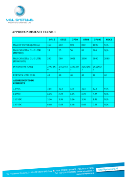
Anweisungen zur Installation
SINEAX VS50 - 162983
SPANNUNG/STROM-WANDLER
MIT GALVANISCHER DREIPUNKTISOLIERUNG
Allgemeine Beschreibung
V/I
-
+
OUTPUT
5
6
4
3
2
1
2
3
4
Range : -150..650 °C
Load : R I < 500 W / R V > 2 k W
m kV, 50 Hz, 1 min
Test Voltage : 1.5
Amb. Temp. : -20..+65 °C
1
T
INPU
SW1
SW2
PUT
OUT
1
0
SUP
INPUT
5
SW1
POWER
SUPPLY
1
0
+
19.2..30 Vdc 7
P < 500 mW 8
+
6
0 °C
2 k W min
0..65 / R V >
1
0 W , 50 Hz,
e : -15
Rang : R I < 50 1.5
m kV °C
Load Voltage : -20..+65
Test Temp. :
Amb.
-
+
7
Vdc
19.2..30 mW 8 POWER
P < 500
PLY
Die Eigenschaften des Wandlers sind die stark begrenzten Abmessungen (6,2 mm), die
Verankerung auf DIN-Schiene zu 35 mm, die Möglichkeit der Speisung über Bus, die
schnellen Anschlüsse über Federklemmen, die galvanische 3-Wege Trennung und die
Konfigurierbarkeit vor Ort über DIP-Schalter.
V/I
Das Gerät VS50 ist ein Wandler mit galvanischer Dreipunktisolierung, für nach
Industriestandard übliche Spannungs- oder Stromsignale, mit passivem Eingang und
aktivem Ausgang. Die Analog-Digital-Wandlung erfolgt mit einer Auflösung von 14 bit
für jeden Eingangsbereich.
Der Wandler weist außerdem noch folgende Funktionen auf:
Programmierbare Störfrequenzunterdrückung für 50 oder 60 Hz Netzfrequenz
Zuschaltbarer Filter für die Stabilisierung der Anzeige
Invertierbarer Eingang und invertierte Ausgangsskalen
Programmierbarer Overrange-Bereich (auf 2,5% oder 5%)
Quadratwurzelermittlung
Linearisierung für zylindrische, horizontale Tanks
Das Modul ist für die Montage auf Schienen nach DIN 46277 ausgelegt. Für eine bessere
Belüftung des Moduls empfehlen wir die Montage in vertikaler Stellung sowie die
Vermeidung der Positionierung in Kanälen oder von sonstigen Gegenständen, die eine
Belüftung behindern.
Vermeiden Sie die Installation des Moduls über Geräten, die Wärme erzeugen; wir
empfehlen die Installation im unteren Bereich der Schalttafel oder des Gehäuses.
Wir empfehlen die Montage auf der Schiene mit dem entsprechenden Anschlussbus
(Bestellnr. CB-Power-Bus), der das Anschließen der Speisung an jedes einzelne Modul
überflüssig macht.
Montage des Moduls in der Schiene
Entfernung des Moduls von der Schiene
SW2
Stromeingang (max. 24 V) :
Zugelassener EingangsOverrange-Bereich :
Ausgangsspannung :
Ausgangsstrom :
Zugelassene OverrangeHöchstgrenzwert :
Strom Ausgangsschutz :
Verarbeitung :
ADC :
19,2..30 Vdc
Max. 22 mA bei 24 Vdc (mit Stromausgang von 20 mA)
0..15 V, 0..30 V, Eingangsimpedanz: 325 kΩ
0..10 V, 2..10 V, 0..5 V, 1..5 V,
Eingangsimpedanz: 110 kΩ
0..20 mA, 4..20 mA, Eingangsimpedanz: 35 Ω
± 2,5 oder ± 5%, je nach Einstellung (siehe Abschnitt
“Overrange-Grenzwerte“)
0..5 Vdc, 1..5 Vdc, 0..10 Vdc und 10..0 Vdc
Min. Lastwiderstand: 2 kΩ
0..20 mA, 4..20 mA, 20..0 mA und 20..4 mA
Max. Lastwiderstand: 500 Ω
unverstellbar (siehe Abschnitt “OverrangeGrenzwerte”)
annähernd 25 mA
Digital, Bearbeitung im 32-Bit-Floating-Point-Format
14 bit für jeden Eingangsbereich
1 - Setzen Sie das Modul in den oberen
Teil der Schiene ein
2 - Drücken Sie das Modul nach unten
1 - Setzen Sie die CB-Power-Bus Anschlüsse zusammen, um die erforderliche Anzahl von
Positionen zu erzielen (jeder CB-Power-Bus gestattet die Aufnahme von 2 Modulen)
2 - Setzen Sie den CB-Power-Bus in die Schiene ein; setzen Sie ihn dazu auf der oberen
Seite ein und drehen Sie ihn nach unten
WICHTIG: Schenken Sie der Position der vorstehenden Klemmen der Busschiene eine
erhöhte Aufmerksamkeit. Der CB-Power-Bus muss so in die DIN-Schiene gesetzt werden,
so dass die vorstehenden Klemmen links liegen (wie im Bild), anderenfalls sind die
Wandler kopfüber montiert.
bei 50 Hz max. 41 ms ohne Filter und 88 ms mit Filter;
bei 60 Hz max. 35 ms ohne Filter und 74 ms mit Filter.
Übertragung :
Optisch-digital
(1)
Übertragungsfehler max. : 0,08% des Vollausschlags für den Ausgang mA oder 5 V
0.07% des Vollausschlags für den Ausgang 10 V
(1)
Auflösung :
1 mV für den Spannungsausgang, 2 mA für den
Stromausgang
Temperaturdrift :
< 120 ppm/K
(2) (3)
Fehler bei der SQRT
:
Im Bereich von 1..100%: 32-bit-floating-point Format
Fehler bei der Linearisierung 0,05%
(2)
des zylindrischen Tanks :
Isolierungsspannung :
1,5 kV zwischen allen Portpaaren
Schutzart:
IP20
Umgebungsbedingungen :
Temperatur -20..+65 °C
Luftfeuchtigkeit 30..90 %, nicht kondensierend
Einsatzhöhe: bis 2000 m über dem Meeresspiegel
Lagertemperatur :
-40..+85 °C
LED-Anzeigen :
Begrenzung des Eingangs-oder Ausgangs-OverrangeBereichs, Sättigung des Eingangs, interner Schaden.
Anschlüsse :
Federklemmen
2
Leiterquerschnitt :
0,2..2,5 mm
Abisolierung der Leiter :
8 mm
Gehäuse :
PBT (schwarze Farbe)
Abmessungen, Gewicht :
6,2 x 93,1 x 102,5 mm, 50 g.
Normen :
EN61000-6-4/2002 (elektromagnetische Emission,
industrielle Umgebung)
EN61000-6-2/2005 (elektromagnetische Immunität,
industrielle Umgebung)
EN61010-1/2001 (Sicherheit)
Alle Schaltungen müssen mit doppelter Isolierung gegen
Schaltungen mit gefährlicher Spannung isoliert werden.
Der Speisungstransformator muss der Norm EN60742:
“Isolierungstransformatoren und
Sicherheitstransformatoren” entsprechen.
(1)
Keine Linearisierungsfunktion eingeschalten.
(2)
Die Linearisierungsfunktionen arbeiten nur im Nominalbereich von 0…100%, während
im Underrange- und im Overrange-Bereich das Eingangssignal ohne jegliche
Veränderung (G=1) übertragen wird. Die Kontinuität und die Gleichmäßigkeit der
Übertragung sind im gesamten messbaren Bereich garantiert.
(3)
In der Strecke 0…1% ist die Kurve linear mit einem Gewinn von G=10, um überflüssige
Rauschamplifikation im ersten Teil des Meßbereichs zu vermeiden.
SINEAX VS50
- Schließen Sie nie die Speisung direkt am Bus der DIN-Schiene an.
- Greifen Sie die Speisung weder direkt, noch über die Klemmen der Module ab.
DEUTSCH - 1/8
Reaktionszeit (10-90%) :
DEUTSCH - 2/8
1 - Hebeln Sie mit einem Schraubenzieher
(wie auf der Abbildung gezeigt)
2 - Drehen Sie das Modul nach oben
Einsatz des CB-Power-Bus
!
SINEAX VS50
Input
Das Modul empfängt ein Eingangssignal in Strom oder Spannung.
Wir empfehlen, für den elektrischen Anschluss abgeschirmte Kabel zu verwenden.
Spannungseingang
Klemme 1: Spannungseingang bis zu 30 Vdc (Belastbarkeit 0..15 Vdc und 0..30 Vdc).
Klemme 2: Spannungseingang bis zu 10 V.
Klemme 4: Rückkehr (GND)
AUSGANGSSIGNAL
SW2 1 2 3
0..20 mA
4..20 mA
20..0 mA (5)
(5)
20..4 mA
0..10 Vdc
0..5 Vdc
1..5 Vdc
2..10 Vdc
(5)
Es handelt sich um invertierte Ausgangsskalen. Diese sind dann besonders nützlich,
wenn die angewandte Linearisierung mit der Eingangsinversion nicht kompatibel ist.
SINEAX VS50
Overrange-Grenzwert ± 2,5%
20,5 mA
3,5 mA
0 mA
30,75 Vdc
15,375 Vdc
10,25 Vdc
5,125 Vdc
0,875 Vdc
1,75 Vdc
0 Vdc
DEUTSCH - 3/8
SINEAX VS50
Werkseinstellung
0..20 mA
50 Hz
Zugeschalten
Nein
Nein
0..20 mA
Grenzwerte ± 5% limit
Obige Einstellungen sind also nur gültig, wenn alle DIP-Schalter auf OFF stehen. Wird
auch nur ein DIP-Schalter verändert, ist es erforderlich, alle anderen Parameter wie folgt
neu einzustellen.
MERKE: Für alle nachfolgenden Tabellen
Die Angabe von zeigt an, dass der DIP-Schalter in Position ON steht (AN).
Keine Angabe bedeutet, dass der DIP-Schalter in der Position OFF steht (AUS).
SINEAX VS50
DEUTSCH - 4/8
+
V
3
mA
4
4
4
4
Ausgang
Spannungsanschluss - Stromanschluss (Fremdstrom).
Wir empfehlen, für den elektrischen Anschluss abgeschirmte Kabel zu verwenden.
+
-
5
1
OUTPUT
6
2
INPUT
7
8
3
4
POWER
SUPPLY
Anmerkung: Zur Reduzierung der
Dissipation des Instruments sollte der
Spannungsausgang verwendet oder eine Last von > 250 Ω am Stromausgang garantiert
werden.
SINEAX VS50
DEUTSCH - 7/8
LED (rot)
Blinken
Konstantes
Leuchten
Bedeutung
Interner Schaden
Begrenzung des Eingangs- oder Ausgangs-Overrange-Bereichs
oder Sättigung des Eingangs.
Hinweis: Bei internem Schaden bleibt der Ausgangswert null.
8 mm
1
OUTPUT
1 - Direkte Speisung der Module durch Anschluss
der Speisung von 24 Vdc direkt an die Klemmen
7 (+) und 8 (-) jedes einzelnen Moduls
(*) Der Filter erhöht die Störfrequenzunterdrückung und stabilisiert die Anzeige, indem
er das Signalrauschen verringert. Daher ist es besser, den Filter immer zuzuschalten,
außer in den Fällen in denen maximale Reaktionsgeschwindigkeit erfordert wird.
INVERTIERUNGSMÖGLICHKEIT
SW1 6
Ja
Nein
2
V
3
Strom
0,2..2,5 mm2
Es bestehen verschiedene Möglichkeiten für die
Speisung der Module der Serie VS.
EINGANGSFILTER (*)
SW1 5
Ja
Nein
+
2
INPUT
7
Spannung
max 10 Vdc
Anzeige mit LED auf der Front
Spannungsversorgung
STÖRFREQUENZUNTERDRÜCKUNG FÜR
50-60 Hz NETZFREQUENZ
SW1 4
60 Hz
50 Hz
OUTPUT
DEUTSCH - 5/8
5
EINGANGSSIGNAL
SW1 1 2 3
0..20 mA
4..20 mA
0..10 Vdc
2..10 Vdc
1..5 Vdc
0..5 Vdc
0..30 Vdc
0..15 Vdc
Spannung
max 30 Vdc
1
1
6
V/I
Das Modul besitzt Federklemmen für die elektrischen
Anschlüsse.
Nehmen Sie bei den Anschlüssen auf die folgenden
Anweisungen Bezug:
1 Entfernen Sie 0,8 cm der Isolierung am Ende der
Kabel
2 Führen Sie einen Schraubenzieher in die
quadratische Öffnung ein und drücken Sie ihn, bis sich
die Feder öffnet, die das Kabel blockiert
3 Führen Sie das Kabel in die runde Öffnung ein
4 Ziehen Sie den Schraubenzieher heraus und
überprüfen Sie, ob das Kabel sicher in der Klemme
befestigt ist.
Alle DIP-Schalter des Moduls befinden sich in der Position OFF als
Standardkonfiguration.
Eingangssignal
Störfrequenzunterdrückung für 50 oder
60 Hz Netzfrequenz
Eingangsfilter
Invertierungsmöglichkeit
Linearisierung
Ausgangssignal
Eingangs-Overrange-Bereich
Overrange-Grenzwert ± 5%
21 mA
3 mA
0 mA
31,5 Vdc
15,75 Vdc
10,5 Vdc
5,25 Vdc
0,75 Vdc
1,5 Vdc
0 Vdc
Elektrische Verbindung
EINSTELLUNG DER DIP-SCHALTER
5
POWER
SUPPLY
Overrange-Grenzwerte
Die programmierbaren Overrange-Grenzwerte, die in der untenstehenden Tabelle
angeführt sind, gelten für das Eingangssignal. Für das Ausgangssignal gelten folgende,
unverstellbare Grenzwerte: 0..21 mA, 0..5,25 Vdc, 0..10,5 Vdc.
Nominalwert
20 mA
4 mA
0 mA
30 Vdc
15 Vdc
10 Vdc
5 Vdc
1 Vdc
2 Vdc
0 Vdc
Stromeingang
Klemme 3: Stromeingang
Klemme 4: Rückkehr (GND)
8
EINGANGS-OVERRANGE-BEREICH
SW2 4
5%
2.5%
Technische Eigenschaften
Spannungsversorgung :
Leistungsaufnahme :
Spannungseingang (max. 50 V) :
Spannungseingang (max. 30 V) :
FUNKTION
SW1 7 8
Vorgabe
Keine
Quadratwurzel (SQRT)
Tank
6
2
+
19.2..30 Vdc 7
8
INPUT
3
4
POWER
SUPPLY
2 - Verwendung des Zubehörartikels CB-Power-Bus für die Verteilung der Speisung an die
Module über Bus, wodurch die Speisung jedes einzelnen Moduls überflüssig wird.
Über den Bus können alle Module gespeist werden; die Gesamtleistungsaufnahme des
Busses muss unter 400 mA liegen. Bei größeren Leistungsaufnahmen können die Module
beschädigt werden. In die Speisung muss eine entsprechend bemessene Sicherung in
Reihe eingesetzt werden.
3 - Verwendung des Zubehörartikels CB-Power-Bus für die Distribution der Speisung der
Module über Bus sowie des Zubehörartikels VS70 für den Anschluss an die Speisung.
Das VS70 ist ein Modul mit einer Breite von 6,2 mm, das eine Reihe von
Schutzschaltungen zum Schutz der über den Bus angeschlossenen Module gegen
eventuelle Überspannungen aufweist.
Der Bus kann über ein Modul VS70 gespeist werden, falls die Gesamtleistungsaufnahme
des Busses unter 1,5 A liegt. Bei höheren Leistungsaufnahmen können das Modul oder
der Bus beschädigt werden. In die Speisung muss eine entsprechend bemessene
Sicherung in Reihe eingesetzt werden.
SINEAX VS50
DEUTSCH - 6/8
Entsorgung von alten Elektro und Elektronikgeräten (gültig in der Europäischen Union und anderen
europäischen Ländern mit separatem Sammelsystem)
Dieses Symbol auf dem Produkt oder auf der Verpackung bedeutet, dass dieses Produkt nicht wie HausmuII
behandelt werden darf. Stattdessen soll dieses Produkt zu dem geeigneten Entsorgungspunkt zum Recyclen
von Elektro und Elektronikgeräten gebracht werden. Wird das Produkt korrekt entsorgt, helfen Sie mit,
negativen Umwelteinflüssen und Gesundheitsschäden vorzubeugen, die durch unsachgemäße Entsorgung
verursacht werden könnten. Das Recycling von Material wird unsere Naturressourcen erhalten. Für nähere
Informationen über das Recyclen dieses Produktes kontaktieren Sie bitte Ihr lokales Bürgerbüro, Ihren
HausmüllAbholservice oder das Geschäft, in dem Sie dieses Produkt gekauft haben.
Camille Bauer AG
Aargauerstrasse 7
CH-5610 Wohlen/Switzerland
Phone +41 56 618 21 11
Fax +41 56 618 35 35
e-Mail: [email protected]
http://www.camillebauer.com
SINEAX VS50
MI001860-F/D
D
DEUTSCH - 8/8
Installation rules
SINEAX VS50 - 162983
V - mA CONVERTER
WITH 3-POINT GALVANIC INSULATION
General Description
Inserting the module in the rail
Removing the module from the rail
OUT
INPUT
6
5
4
3
2
1
T
1
INPU
SW2
PUT
SW1
2
3
4
Range : -150..650 °C
Load : R I < 500 W / R V > 2 k W
m kV, 50 Hz, 1 min
Test Voltage : 1.5
Amb. Temp. : -20..+65 °C
-
SW1
+
POWER
SUPPLY
1
0
V/I
+
5
V/I
OUTPUT
6
+
19.2..30 Vdc 7
P < 500 mW 8
Amb.
0 °C
2 k W min
0..65 / R V >
1
0 W , 50 Hz,
e : -15
Rang : R I < 50 1.5
m kV °C
Load Voltage : -20..+65
Test Temp. :
1
0
SUP
+
7
Vdc
19.2..30 mW 8 POWER
P < 500
PLY
SW2
The VS50 instrument is a V - mA converter with 3-point galvanic insulation designed for
industrial standard voltage or current signals with passive input and active output.
Analogue/digital conversion takes place at 14 bit on every input range.
The instrument also provides the following functions:
Rejection programmable for 50 or 60 Hz mains frequency.
Additional reading stabilisation filter.
Inversion of the input and inverted output scales
Input Out-of-Range programmable to 2.5% or 5.0%
SQRT function.
Linearisation for horizontal cylindrical tanks.
The module is also characterised by its extremely compact size, coupling to 35 mm DIN
driver, power supply available by bus, quick fit couplings by spring-type terminals, 3point insulation, onsite configuration by DIP-switch.
This module has been designed for assembly on a DIN 46277 rail. Assembly in vertical
position is recommended in order to increase the module's ventilation, and no raceways or
other objects that compromise aeration must be positioned in the vicinity.
Do not position the module above equipment that generates heat; we recommend
positioning the module in the lower part of the control panel or container compartment.
We recommend rail-type assembly using the corresponding bus connector (Code CBPower-Bus) that eliminates the need to connect the power supply to each module.
Technical Features
Power supply :
Consumption :
Voltage input (max. 50 V) :
Voltage input (max. 30 V) :
Current input (max. 24 V) :
Permissible max. Input Out-ofRange :
19,2..30 Vdc
Max 22 mA at 24 Vdc ( 20 mA output )
0..15 V, 0..30 V, Input Impedance: 325 kΩ
0..10 V, 2..10 V, 0..5 V, 1..5 V,
Input Impedance: 110 kΩ
0..20 mA, 4..20 mA, Input Impedance: 35 Ω
± 2,5 or ± 5% depending on setting (see section on
Input Out-of-Range Limits)
Voltage output :
0..5 Vdc, 1..5 Vdc, 0..10 Vdc and 10..0 Vdc
Minima load resistance: 2 KΩ
Current output :
0..20 mA, 4..20 mA, 20..0 mA e 20..4 mA
Maximum load resistance: 500 Ω
Maximum applied Voltage :
± 30 V
Permissible max. Output Out-of- Fixed (see section on Output Out-of-Range Limits)
Range:
Current output protection :
approximately 25 mA
Digital, 32 bit floating-point calculation
14 bit on every input range
Processing :
ADC :
SINEAX VS50
10-90% response :
Transmission :
Max. transmission error
(1)
:
50 Hz : max 41 ms without filter and 88 ms with filter;
60 Hz : max 35 ms without filter and 74 ms with filter.
Digital Optical
0.08% of the f.s. value for mA or 5 V output
0.07% of the f.s. value for 10 V output
1 mV for voltage output, 2 uA for current output
Lower than 120 ppm/K
in the range 1..100%: floating point 32 bit
Connections :
Conductor Section :
Wire stripping :
1,5 KV (50 Hz for 1 min )
IP20
Temperature -20..+65 °C
Humidity 30..90 % at 40°C (non-condensing)
Altitudine 2000 slm
-40..+85 °C
Input or output out-of-range limiter device triggered or
input saturation. Internal fault.
Spring terminals
0,2..2,5 mm2
8 mm
Box :
PBT (black colour)
Dimensions, Weight :
6,2 x 93,1 x 102,5 mm, 50 g.
Standards :
EN50081-2 (electromagnetic emission, industrial
surroundings)
EN50082-2 (electromagnetic immunity, industrial
surroundings)
EN61010-1 (safety)
All the circuits must be provided with double insulation
from the circuits under dangerous voltage. The power
supply transformer must be built to compliance with
EN60742: “Insulation transformers and Safety
transformers”.
Storage Temperature :
LED Signalling :
(1)
No linearisation function connected
(2)
Linearisation functions operate only in the 0..100% rated range, whereas for the
under-range and the over-range, the input signal is transferred without any alteration
(G=1). Continuity and monotonic quality of transfer guaranteed throughout the entire
range of measurement
(3)
In the 0..1% section, the curve is linear with gain G=10 in order to avoid overamplification of the noise in the initial section of the measurement range.
SINEAX VS50
ENGLISH - 2/8
1 - Apply leverage using a screwdriver (as
shown in the figure).
2 - Rotate the module upwards.
Using the CB-Power-Bus connector
1 - Compose the CB-Power-Bus connectors as required in order to obtain the number of
positions necessary (each CB-Power-Bus permits the insertion of no. 2 modules).
2 - Insert the CB-Power-Bus connectors in the rail by positioning them on the upper side of
the rail and then rotating them downwards.
IMPORTANT: Pay particular attention to the position of the protrudent terminals of the
CB-Power-Bus. The CB-Power-Bus must be inserted in the guide with the protrudent
terminals on the left (as shown in the figure) otherwise the modules are turned upside
downs.
- Never connect the power supply directly to the bus connector on the DIN rail.
- Never tap power supply from the bus connector either directly or by using
the module's terminals.
Input
The module accepts a current or voltage input signal.
The use of shield cables is recommended for the electronic connections.
OUTPUT SIGNAL
SW2 1 2 3
0..20 mA
4..20 mA
20..0 mA (5)
(5)
20..4 mA
0..10 Vdc
0..5 Vdc
1..5 Vdc
2..10 Vdc
(5)
These are inverse output ranges that are useful whenever the linearisation applied is
incompatible with the inversion of the input.
SINEAX VS50
INPUT OUT-OF-RANGE
SW2 4
5%
2.5%
5
Voltage
max 30 Vdc
1
1
OUTPUT
6
+
2
INPUT
7
Voltage
max 10 Vdc
2
V
3
Current
+
3
V
mA
4
4
4
4
POWER
SUPPLY
The Out-of-Range Limits provided in the following table are applied to the input signal,
whereas the fixed limits are applied to the output signal: 0..21 mA, 0..5,25 Vdc, 0..10,5
Vdc.
Rated value
Input Out-of-Range Limit ± 2,5 % Input Out-of-Range Limit ± 5 %
20 mA
20,5 mA
21 mA
4 mA
3,5 mA
3 mA
0 mA
0 mA
0 mA
30 Vdc
30,75 Vdc
31,5 Vdc
15 Vdc
15,375 Vdc
15,75 Vdc
10 Vdc
10,25 Vdc
10,5 Vdc
5,25 Vdc
5,125 Vdc
5 Vdc
0,75 Vdc
0,875 Vdc
1 Vdc
1,5 Vdc
1,75 Vdc
2 Vdc
0 Vdc
0 Vdc
0 Vdc
Output
Voltage connection - Current connection (applied current)
The use of shield cables is recommended for the electronic connections.
V/I
+
-
5
1
OUTPUT
6
2
INPUT
7
8
3
4
POWER
SUPPLY
Note: in order to reduce the instrument's dissipation, we recommend either using the
output for voltage or guaranteeing a load of > 250 Ω to the current output.
ENGLISH - 5/8
SINEAX VS50
Electrical Connections
Factory setting
0..20 mA
50 Hz
Present
No
None
0..20 mA
± 5% limit
SINEAX VS50
ENGLISH - 7/8
LED indications on the front
The module has been designed for spring-type terminal
electrical connections.
Proceed as follows to make the connections:
1 - Strip the cables by 0.8 mm
2 - Insert a screwdriver in the square hole and press it
until the cable lock spring opens.
3 - Insert the cable in the round hole.
4 - Remove the screwdriver and make sure that the cable
is tightly fastened in the terminal.
All the module DIP switches are at pos. 0 as defaut configuration.
This set correspond to the following configuration :
Input signal
50-60 Hz mains frequency rejection
Input filter
Inversion
Linearisation
Output signal
Input Out-of-range
Current input
Terminal 3: Current input.
Terminal 4: Return
Input Out-of-Range Limits
ENGLISH - 3/8
SETTING OF THE DIP-SWITCHES
Voltage input
Terminal 1: Voltage input up to 30 VDC (current carrying capacity 0..15 VDC and 0..30
VDC).
Terminal 2: Voltage input up to 10 V.
Terminal 4: Return
8
!
ENGLISH - 1/8
Resolution (1) :
Thermal drift :
SQRT error (2) (3) :
Linearisation error Cylindrical
0,05%
tank (2) :
Insulation Voltage :
Protection Index :
Operating Conditions :
1 - Attach the module in the upper part of
the rail.
2 - Press the module downwards.
FUNCTION
SW1 7 8
Default
None
SQRT
Tank
LED (Red)
Flashing
Steady light
Meaning
Internal fault.
Input or output out-of-range limiter device triggered or input
saturation.
Note: in case of internal fault, the output will stay at null value.
It is understood that this configuration is valid only with all the DIP switches at position 0.
If also one Dip is moved, it is necessary to set all the other parameter as indicated on
the following tables.
0,2..2,5 mm2
Note: for all following tables
The indication indicates that the DIP-switch is set in Position 1 (ON).
No indication is provided when the DIP-switch is set in Position 0 (OFF).
8 mm
5
INPUT SIGNAL
SW1 1 2 3
0..20 mA
4..20 mA
0..10 Vdc
2..10 Vdc
1..5 Vdc
0..5 Vdc
0..30 Vdc
0..15 Vdc
There are various ways to provide the VS Series
modules with power.
1 - Direct power supply to the modules by
connecting 24 Vdc power supply directly to
Terminals 7 ( + ) and 8 ( - ) of each module.
50-60 Hz MAINS FREQUENCY REJECTION
INPUT FILTER (*)
SW1 4
SW1 5
60 Hz
Present
50 Hz
Absent
(*) The filter increases the rejection of the disturbance to the mains frequency, and
stabilizes the reading reducing the measure noise. It is advised to hold it always
inserted, but that the maximum speed of answer is not demanded.
INVERSION
SW1 6
Present
Absent
SINEAX VS50
ENGLISH - 4/8
1
OUTPUT
Power supply
6
2
+
19.2..30 Vdc 7
8
INPUT
3
4
POWER
SUPPLY
2 - Using the CB-Power-Bus connector accessory for the distribution of the power supply to
the modules via bus connector, in this way eliminating the need to connect power supply to
each module.
The bus can be supplied from any of the modules; the total absorption of the bus must be
less than 400 mA. Higher absorption values can damage the module. An appropriately
sized fuse must be connected in series to the power supply.
3 - Using the CB-Power-Bus connector accessory for the distribution of the power supply to
the modules via bus connector and the VS70 accessory for the connection of the power
supply.
The VS70 accessory is a 6.2 mm wide module that contains a set of protections designed
to protect the modules connected via bus against over-voltage loads.
The bus connector can be provided with power using the VS70 module if the total
absorption of the bus is less than 1.5 A. Higher absorption values can damage both the
module and the bus. An appropriately sized fuse must be connected in series to the power
supply.
SINEAX VS50
ENGLISH - 6/8
Smaltimento dei rifiuti elettrici ed elettronici (applicabile nell’Unione Europea e negli altri
paesi con servizio di raccolta differenziata).
Il simbolo presente sul prodotto o sulla sua confezione indica che il prodotto non verrà trattato
come rifiuto domestico. Sarà invece consegnato al centro di raccolta autorizzato per il riciclo dei
rifiuti elettrici ed elettronici. Assicurandovi che il prodotto venga smaltito in modo adeguato,
eviterete un potenziale impatto negativo sull’ambiente e la salute umana, che potrebbe essere
causato da una gestione non conforme dello smaltimento del prodotto. Il riciclaggio dei materiali
contribuirà alla conservazione delle risorse naturali. Per ricevere ulteriori informazioni più
dettagliate Vi invitiamo a contattare l’ufficio preposto nella Vostra città, il servizio per lo
smaltimento dei rifiuti o il fornitore da cui avete acquistato il prodotto.
Camille Bauer AG
Aargauerstrasse 7
CH-5610 Wohlen/Switzerland
Phone +41 56 618 21 11
Fax +41 56 618 35 35
e-Mail: [email protected]
http://www.camillebauer.com
SINEAX VS50
MI001860-I/E
EN
ENGLISH - 8/8
Normes d'installation
SINEAX VS50 - 162983
CONVERTISSEUR V - mA
AVEC ISOLATION GALVANIQUE À TROIS POINTS
Description générale
Montage du module dans le guide
Extraction du module du guide
OUT
INPUT
6
5
4
3
2
1
T
1
INPU
SW2
PUT
SW1
2
3
4
Range : -150..650 °C
Load : R I < 500 W / R V > 2 k W
m kV, 50 Hz, 1 min
Test Voltage : 1.5
Amb. Temp. : -20..+65 °C
-
SW1
+
POWER
SUPPLY
1
0
V/I
+
5
V/I
OUTPUT
6
+
19.2..30 Vdc 7
P < 500 mW 8
Amb.
0 °C
2 k W min
0..65 / R V >
1
0 W , 50 Hz,
e : -15
Rang : R I < 50 1.5
m kV °C
Load Voltage : -20..+65
Test Temp. :
1
0
SUP
Le module a aussi les caractéristiques suivantes : encombrement réduit (6,2 mm),
fixation sur guide DIN 35 mm, alimentation possible par bus, connexions rapides à l'aide
de bornes à ressort, isolation trois points, possibilité de configuration sur site à l'aide de
commutateurs DIP.
+
7
Vdc
19.2..30 mW 8 POWER
P < 500
PLY
L'instrument VS50 est un convertisseur avec isolation galvanique à trois points, pour les
signaux en tension ou en courant conformes à la norme industrielle, avec une entrée
passive et une sortie active.
La conversion analogique-numérique est à 14 bits sur chaque plage en entrée.
Il dispose en outre des fonctionnalités suivantes :
Réjection programmable pour 50 Hz ou 60 Hz de réseau
Filtre supplémentaire pour stabiliser la lecture
Inversion de l'entrée et échelles de sortie inverties
Hors-échelle de l'entrée programmable à 2,5% ou 5%
Extraction de racine
Linéarisation pour réservoirs cylindriques horizontaux
Le module est conçu pour être monté sur rail DIN 46277. Afin d'en favoriser l'aération, il
est conseillé de le monter à la verticale, en évitant les moulures ou autres objets pouvant
empêcher la circulation d'air.
Éviter de poser le module sur des appareils qui dégagent de la chaleur ; il est conseillé de
le placer en bas du tableau ou de l'armoire.
Il est conseillé de le monter sur rail à l'aide du connecteur bus prévu à cet effet (code CBPower-Bus) qui évite de devoir brancher l'alimentation sur chaque module.
SW2
19,2..30 Vdc
max 22 mA à 24 Vdc (avec sortie à 20 mA)
0..15 V, 0..30 V, Impédance en entrée: 325 kΩ
0..10 V, 2..10 V, 0..5 V, 1..5 V, Impédance en entrée:
110 kΩ
Entrée en Courant (max 24 V): 0..20 mA, 4..20 mA, Impédance en entrée: 35 Ω
Hors-échelle entrée admis:
± 2,5 ou ± 5% selon la configuration
(cf. section Limites Hors-échelle)
0..5 Vdc, 1..5 Vdc, 0..10 Vdc et 2..10 Vdc
Résistance minimale de charge 2 KΩ
Sortie en courant :
0..20 mA, 4..20 mA, 20..0 mA, 20..4 mA
Résistance maximale de charge 500 Ω
Maximum Hors-échelle admis : Fixe (cf. section Limites Hors-échelle)
Protection de la sortie en
environ 25 mA
courant :
Numérique, Calcul en point flottant 32 bits
Elaboration :
14 bits sur chaque plage d'entrée
ADC :
Sortie en tension :
SINEAX VS50
À 50 Hz max 41 ms sans filtre et 88 ms avec filtre engagé;
À 60 Hz maxi 35 ms sans filtre et 74 ms avec filtre engagé.
Optique Numérique
Transmission :
0,08% du bas d'échelle pour sortie mA ou 5 V
(1)
Erreur max de transmission : 0,07% du bas d'échelle pour sortie 10 V
(1)
Résolution :
1 mV pour sortie en tension, 2mA pour sortie en courant
Dérive Thermique :
Inférieure à 120 ppm/K
(2) (3)
Erreur sur SQRT
:
Dans la plage 1..100% point flottant 32 bits
Erreur sur linéarisation
(2)
0,05%
Réservoir Cylindrique :
1,5 kV entre chaque paire de portes.
IP20
Température -20..+65 °C
Humidité 10..90 % sans condensation.
Altitude : 2000 mètres
-40..+85 °C
Temp. de stockage :
Intervention limite hors-échelle de l'entrée ou de la sortie,
Signalisations par DEL :
saturation de l'entrée, panne interne.
Bornes à ressort
Connexions :
2
0,2..2,5 mm
Section des conducteurs :
Dénudage des conducteurs: 8 mm
Boîtier :
PBT noir
Tension d'isolation :
Degré de protection :
Conditions ambiantes :
Dimensions, Poids :
6,2 x 93,1 x 102,5 mm, 46 g.
Normes :
EN61000-6-4/2002 (émission électromagnétique, milieu
industriel)
EN61000-6-2/2005 (immunité électromagnétique, milieu
industriel)
EN61010-1/2001 (sécurité)
Tous les circuits doivent être isolés avec une double
isolation des circuits sous tension dangereuse. Le
transformateur d'alimentation doit être conforme à la
norme EN60742 : “Transformateurs d'isolation et
transformateurs de sécurité”.
(1)
Aucune fonction de linéarisation engagée
(2)
Les fonctions de linéarisation n'agissent que dans la plage nominale 0..100%, alors
qu'en cas de valeurs au-dessous ou au-dessus de la plage le signal d'entrée est transféré
sans aucune altération (G=1). La continuité est garantie ainsi que la monotonicité du
transfert sur toute la plage mesurable.
(3)
Dans la partie 0..1% la courbe est linéaire avec un gain G=10, pour éviter l'amplification
excessive du bruit dans la partie initiale de la plage de mesure.
SINEAX VS50
1 - Accrocher le module dans la partie
supérieure du guide
2 - Pousser le module vers le bas
FRANÇAIS - 2/8
1 - Faire levier avec un tournevis (comme
indiqué sur la figure)
2 - Pivoter le module vers le haut
Utilisation du CB-Power-Bus
1 - Assembler les connecteurs CB-Power-Bus afin d'obtenir le nombre d'emplacements
nécessaires (chaque CB-Power-Bus permet d'insérer 2 modules)
2 - Placer les CB-Power-Bus dans le rail en les introduisant par le haut et les tourner vers le
bas.
IMPORTANT: Le CB-Power-Bus doit être inséré dans la guide avec les connecteurs
tournés vers gauche (comme montré dans la figure), en cas contraire les modules
résulteraient renversés.
- Ne jamais brancher l'alimentation directement au bus sur le guide DIN.
- Ne pas prélever directement l'alimentation du bus, ni à l'aide des bornes des
modules.
Pour les branchements électriques nous vous recommandons d'utiliser des câbles
blindés.
SIGNAL DE SORTIE
SW2 1 2 3
0..20 mA
4..20 mA
20..0 mA (5)
(5)
20..4 mA
0..10 Vdc
0..5 Vdc
1..5 Vdc
2..10 Vdc
(5)
Il s'agit d'échelles de sortie inverses, utiles lorsque la linéarisation appliquée n'est pas
compatible avec l'inversion de l'entrée.
Limites hors-échelle
Les limites programmables de hors-échelle indiquées dans le tableau suivant s'appliquent
au signal d'entrée, les limites fixe s'appliquent à la sortie: 0..21 mA, 0..5,25 Vdc, 0..10,5
Vdc.
Valeur Nominale
20 mA
4 mA
0 mA
30 Vdc
15 Vdc
10 Vdc
5 Vdc
1 Vdc
2 Vdc
0 Vdc
SINEAX VS50
Limite de hors-échelle ± 2,5 %
20,5 mA
3,5 mA
0 mA
30,75 Vdc
15,375 Vdc
10,25 Vdc
5,125 Vdc
0,875 Vdc
1,75 Vdc
0 Vdc
Limite de hors-échelle ± 5 %
21 mA
3 mA
0 mA
31,5 Vdc
15,75 Vdc
10,5 Vdc
5,25 Vdc
0,75 Vdc
1,5 Vdc
0 Vdc
SINEAX VS50
5
Tension
jusqu'à 30 Vdc
1
1
OUTPUT
6
8
Tension
jusqu'à 10 Vdc
+
2
INPUT
7
2
V
3
Courant
+
3
V
mA
4
4
4
4
Sortie
Branchement en tension - Branchement en courant (courant contraint).
Pour les branchements électriques nous vous recommandons d'utiliser des câbles
blindés.
V/I
+
-
5
1
OUTPUT
6
2
INPUT
7
8
3
4
POWER
SUPPLY
FRANÇAIS - 5/8
Le module dispose de bornes à ressort pour les
branchements électriques.
Pour procéder aux branchements, suivre les instructions
suivantes :
1 - Dénuder les câbles sur 0,8 mm
2 - Placer un tournevis plat dans le trou carré et
appuyer pour ouvrir le ressort de blocage du câble
3 - Introduire le câble dans le trou rond
4 - Enlever le tournevis et vérifier si le câble est fixé
solidement à la borne.
Le convertisseur sort de la fabrique avec tous les commutateurs DIP en position OFF.
Dans cette position le convertisseur charge à l’alimentation la configuration suivante (sauf
differente indication sur le boîtier) :
0..20 mA
50 Hz
Engagé
Non
Aucune
0..20 mA
Limites ± 5%
SINEAX VS50
FRANÇAIS - 7/8
Indications par LED sur la partie frontale
Branchements électriques
Positions de Fabrique
Signal d'Entrée
Réjection 50/60 Hz de réseau
Filtre d'entrée
Inversion
Linéarisation
Signal de Sortie
Hors-échelle Entrée
Entrée en Courant
Borne 3: Entrée en Courant
Borne 4: Retour (Terre)
Remarque: afin de réduire la dissipation de l'instrument, il convient garantir une charge
> 250 Ω à la sortie en courant.
FRANÇAIS - 3/8
COMMUTATEURS DIP
Entrée en Tension
Borne 1: Entrée en tension jusqu'à 30 Vdc (débits 0..15 Vdc et 0..30 Vdc).
Borne 2: Entrée en tension jusqu'à 10 Vdc.
Borne 4: Retour (Terre)
POWER
SUPPLY
!
FRANÇAIS - 1/8
Réponse 10-90% :
Entrée
Le module accepte en entrée un signal en courant ou en tension.
HORS-ÉCHELLE ENTRÉE
SW2 4
5%
2.5%
Caractéristiques techniques
Alimentation :
Absorption:
Entrée en tension (max 50 V):
Entrée en tension (max 30 V):
FONCTION
SW1 7 8
Défaut
Aucune
Racine carrée
Réservoir
LED (Rouge)
Clignotante
Significative
Panne interne.
Allume fixement
Intervention de la limite de hors-échelle de l'entrée ou de la sortie
ou saturation de l'entrée.
Remarque: en cas de panne interne la sortie restera sur une valeur nulle.
Cette configuration est valide seulement avec tous les commutateurs DIP en position OFF.
S'il est déplacé même un seul commutateur DIP il est nécessaire de pourvoir à une
complète configuration du convertisseur comme indiqué dans les tableaux suivants.
0,2..2,5 mm2
Remarque: dans tous les tableaux suivants
L’indication correspond au commutateur DIP sur ON;
Aucune indication ne correspond au commutateur DIP sur OFF
8 mm
SIGNAL D'ENTRÉE
SW1 1 2 3
0..20 mA
4..20 mA
0..10 Vdc
2..10 Vdc
1..5 Vdc
0..5 Vdc
0..30 Vdc
0..15 Vdc
5
Les modules de la série VS peuvent être alimentés
de plusieurs façons.
1 - Alimentation directe des modules en branchant
directement l'alimentation en 24 Vcc aux bornes 7
(+) et 8 (-) de chaque module.
RÉJECTION (50/60 Hz) DE RÉSEAU
FILTRE D'ENTRÉE (*)
SW1 4
SW1 5
60 Hz
Présent
50 Hz
Absent
(*) Le filtre augmente la réjection des parasites à la fréquence du secteur et stabilise la
lecture en réduisant les parasites de mesure. Nous conseillons de toujours laisser le
filtre engagé, sauf si vous avez besoin d'une vitesse de réponse maximum.
INVERSION
SW1 6
Présent
Absent
SINEAX VS50
FRANÇAIS - 4/8
1
OUTPUT
Alimentation
6
2
+
19.2..30 Vdc 7
8
INPUT
3
4
POWER
SUPPLY
2 - Utilisation de l'accessoire CB-Power-Bus pour distribuer l'alimentation aux modules à
l'aide du bus en évitant de devoir brancher chaque module.
Le bus peut être alimenté à partir de n'importe quel module, la consommation totale du bus
doit être inférieure à 400 mA. Une consommation supérieure risque d'abîmer le module. Il
est nécessaire de prévoir un fusible ayant des dimensions appropriées sur l'alimentation.
3 - Utilisation de l'accessoire CB-Power-Bus pour distribuer l'alimentation aux modules à
l'aide du bus et de l'accessoire VS70 pour le branchement de l'alimentation.
VS70 est un module de 6,2 mm de large qui contient une série de protections pour
sauvegarder les modules branchés au bus contre toute surtension éventuelle.
Le bus peut être alimenté à partir d'un module VS70 si la consommation totale du bus est
inférieure à 1,5 A. Une consommation supérieure risque d'abîmer le module et le bus. Il est
nécessaire de prévoir un fusible ayant des dimensions appropriées sur l'alimentation.
SINEAX VS50
FRANÇAIS - 6/8
Disposition concernant les équipements électriques et électroniques (applicable dans l'Union
Européenne et dans d'autres pays européens avec des systèmes de collecte séparés)
Ce symbole sur le produit ou sur son emballage indique que ce produit ne sera pas traité comme perte
ménagère. Au lieu de cela il sera remis au point de collecte dédié pour le recyclage de l'équipement
électrique et électronique. En s'assurant que ce produit est trié et jeté correctement, vous contribuerez a
empécher de potentielles consequences négatives pour l'environnement et la santé humaine, qui
pourraient autrement étre provoquées par la manutention de rebut inadéquate de ce produit. La réutilisation
des matériaux aidera à conserver les ressources naturelles. Pour des informations plus détaillées sur la
réutilisation de ce produit, vous pouvez contacter votre mairie, la societé de collecte et tri des rebuts ou le
magasin où vous avez acheté le produit.
Camille Bauer AG
Aargauerstrasse 7
CH-5610 Wohlen/Switzerland
Phone +41 56 618 21 11
Fax +41 56 618 35 35
e-Mail: [email protected]
http://www.camillebauer.com
SINEAX VS50
MI001860-F/D
F
FRANÇAIS - 8/8
Norme di installazione
SINEAX VS50 - 162983
CONVERTITORE V - mA
CON ISOLAMENTO GALVANICO A TRE PUNTI
Descrizione Generale
Inserimento del modulo nella guida
Estrazione del modulo dalla guida
OUT
INPUT
6
5
4
3
2
1
T
1
INPU
SW2
PUT
SW1
2
3
4
Range : -150..650 °C
Load : R I < 500 W / R V > 2 k W
m kV, 50 Hz, 1 min
Test Voltage : 1.5
Amb. Temp. : -20..+65 °C
-
SW1
+
POWER
SUPPLY
1
0
V/I
+
5
V/I
OUTPUT
6
+
19.2..30 Vdc 7
P < 500 mW 8
Amb.
0 °C
2 k W min
0..65 / R V >
1
0 W , 50 Hz,
e : -15
Rang : R I < 50 1.5
m kV °C
Load Voltage : -20..+65
Test Temp. :
1
0
SUP
+
7
Vdc
19.2..30 mW 8 POWER
P < 500
PLY
SW2
Lo strumento VS50 è un convertitore con isolamento galvanico a tre punti, per
segnali a standard industriale in tensione o corrente, con ingresso passivo e uscita
attiva.
La conversione analogico digitale è a 14 bit su ogni range di ingresso.
Esso inoltre è dotato delle seguenti funzionalità:
Reiezione programmabile per i 50 Hz o i 60 Hz di rete
Filtro aggiuntivo per la stabilizzazione della lettura
Inversione dell’ingresso e scale di uscita invertite
Fuori-Scala dell’ingresso programmabile al 2,5% o 5%
Estrazione di radice
Linearizzazione per serbatoi cilindrici orizzontali
Il modulo è inoltre caratterizzato da ridottissimo ingombro, aggancio su guida DIN
35 mm, possibilità di alimentazione tramite bus, connessioni rapide tramite morsetti
a molla, isolamento a tre punti, configurabilità in campo tramite DIP-switch.
Il modulo è progettato per essere montato su guida DIN 46277. Al fine di favorire la
ventilazione del modulo stesso, ne viene consigliato il montaggio in posizione verticale,
evitando di posizionare canaline o altri oggetti che ne impediscano l'aereazione.
Evitare di collocare il modulo sopra apparecchiature che generino calore; è
consigliabile la collocazione nella parte bassa del quadro o del vano di contenimento.
Si consiglia il montaggio a guida tramite l'apposito connettore bus (cod. CB-Power-Bus)
che evita di dover collegare l'alimentazione a ciascun modulo.
19,2..30 Vdc
max 22 mA a 24 Vdc ( con uscita a 20 mA )
0..15 V, 0..30 V, Impedenza di Ingresso: 325 kΩ
0..10 V, 2..10 V, 0..5 V, 1..5 V, Impedenza di
Ingresso: 110 kΩ
Ingresso in Corrente (max 24 V): 0..20 mA, 4..20 mA, Impedenza di Ingresso: 35 Ω
Fuori-scala Ingresso ammesso : ± 2,5 o ± 5% secondo l’impostazione
(vedi sezione Limiti Fuori-scala Ingresso)
Alimentazione :
Assorbimento :
Ingresso in Tensione (max 50 V):
Ingresso in Tensione (max 30 V):
Massima Tensione applicabile :
Massimo Fuori-scala ammesso
Protezione uscita in corrente :
0..5 Vdc, 1..5 Vdc, 0..10 Vdc e 2..10 Vdc
Minima resistenza di carico 2 KΩ
0..20 mA, 4..20 mA, 20..0 mA, 20..4 mA
Massima resistenza di carico 500 Ω
± 30 V
Fisso (vedi Sezione Limiti Fuori-scala Uscita)
circa 25 mA
Elaborazione :
ADC :
Digitale, Calcolo in floating-point 32 bit
14 bit su ogni range di ingresso
Uscita in corrente :
SINEAX VS50
A 50 Hz max 41 ms senza filtro e 88 ms con filtro
inserito; a 60 Hz max 35 ms senza filtro e 74 ms con
filtro inserito.
Trasmissione :
Ottico Digitale
(1)
Errore max di trasmissione : 0,08% del fs per uscita mA o 5 V
0,07% del fs per uscita 10 V
Risoluzione (1) :
1 mV per uscita in tensione, 2mA per uscita in corrente
Deriva Termica :
Inferiore a 120 ppm/K
Errore su SQRT (2) (3) :
Nel range 1..100%: floating point 32 bit
Errore su linearizzazione
0,05%
Serbatoio Cilindrico(2) :
Connessioni :
Sezione dei conduttori :
Spellatura dei conduttori :
1,5 kV tra ciascuna coppia di porte
IP20
Temperatura -20..+65 °C
Umidità 10..90 % non condensante.
Altitudine 2000 slm
-40..+85 °C
Intervento limitazione fuori-scala dell’ingresso o
dell’uscita, saturazione dell’ingresso, guasto interno.
Morsetti a molla
2
0,2..2,5 mm
8 mm
Contenitore :
PBT, colore nero
Temp. Magazzinaggio :
Segnalazioni LED :
Dimensioni, Peso :
6,2 x 93,1 x 102,5 mm, 46 g.
Normative :
EN50081-2 (emissione elettromagnetica, ambiente
industriale)
EN50082-2 (immunità elettromagnetica, ambiente
industriale)
EN61010-1 (sicurezza)
Tutti i circuiti devono essere isolati con doppio
isolamento dai circuiti sotto tensione pericolosa. Il
trasformatore di alimentazione deve essere a norma
EN60742: “Trasformatori di isolamento e trasformatori di
sicurezza”.
(1)
Nessuna funzione di linearizzazione inserita
(2)
Le funzioni di linearizzazione operano solo nel range nominale 0..100%, mentre
per l’under-range e per l’over-range il segnale di ingresso viene trasferito
senza nessuna alterazione (G=1). Viene garantita la continuità e la monotonicità del
trasferimento su tutto il range misurabile.
(3)
Nel tratto 0..1% la curva è lineare con guadagno G=10, per evitare l’eccessiva
amplificazione del rumore nel tratto iniziale del range di misura
SINEAX VS50
1 - Agganciare il modulo nella parte
superiore della guida
2 - Premere il modulo verso il basso
ITALIANO - 2/8
1 - Fare leva con un cacciavite (come
indicato in figura)
2 - Ruotare il modulo verso l'alto
Utilizzo del CB-Power-Bus
1 - Comporre i connettori CB-Power-Bus per ottenere il numero di posizioni necessarie
(ogni CB-Power-Bus permette l'inserimento di nr. 2 moduli)
2 - Inserire i CB-Power-Bus nella guida appoggiandoli dal lato superiore e ruotandoli
verso il basso.
IMPORTANTE: il CB-Power-Bus va inserito nella guida con i connettori sporgenti
rivolti verso sinistra (come indicato nella figura) altrimenti i moduli risulterebbero
capovolti.
- Non collegare mai l’alimentazione direttamente al bus su guida DIN.
- Non prelevare alimentazione dal bus né direttamente né tramite i morsetti
dei moduli.
Il modulo accetta in ingresso un segnale in corrente o tensione.
Per i collegamenti elettrici si raccomanda l’utilizzo di cavo schermato.
Ingresso in Tensione
Morsetto 1: Ingresso in tensione fino a 30 Vdc (portate 0..15 Vdc e 0..30 Vdc).
Morsetto 2: Ingresso in tensione fino a 10 V.
Morsetto 4: Ritorno (GND)
SEGNALE DI USCITA
SW2 1 2 3
0..20 mA
4..20 mA
20..0 mA (5)
(5)
20..4 mA
0..10 Vdc
0..5 Vdc
1..5 Vdc
2..10 Vdc
(5)
Sono scale di uscita inverse, utili quando la linearizzazione applicata non sia
compatibile con l’inversione dell’ingresso.
Ingresso in Corrente
Morsetto 3: Ingresso in corrente.
Morsetto 4: Ritorno (GND)
5
SINEAX VS50
OUTPUT
8
2
V
3
Corrente
+
3
V
mA
4
4
4
4
POWER
SUPPLY
Il limiti programmabili di fuori-scala riportati nella tabella seguente vengono applicati al
segnale di ingresso; per l’uscita valgono i limiti fissi: 0..21 mA, 0..5,25 Vdc, 0..10,5 Vdc.
Valore Nominale
20 mA
4 mA
0 mA
30 Vdc
15 Vdc
10 Vdc
5 Vdc
1 Vdc
2 Vdc
0 Vdc
Limite di fuori-scala ± 2,5 %
20,5 mA
3,5 mA
0 mA
30,75 Vdc
15,375 Vdc
10,25 Vdc
5,125 Vdc
0,875 Vdc
1,75 Vdc
0 Vdc
Uscita
Collegamento in tensione - Collegamento in corrente (corrente impressa).
Per i collegamenti elettrici si raccomanda l’utilizzo di cavo schermato.
Limite di fuori-scala ± 5 %
21 mA
3 mA
0 mA
31,5 Vdc
15,75 Vdc
10,5 Vdc
5,25 Vdc
0,75 Vdc
1,5 Vdc
0 Vdc
V/I
+
5
-
1
OUTPUT
6
2
INPUT
7
8
3
4
POWER
SUPPLY
Nota: quando si utilizza l’uscita in corrente, per ridurre la dissipazione dello strumento,
è conveniente collegare un carico > 250 Ω.
SINEAX VS50
ITALIANO - 5/8
Il modulo dispone per i collegamenti elettrici di morsetti
a molla.
Per effettuare i collegamenti riferirsi alle seguenti
istruzioni:
1 - Spellare i cavi per 0,8mm
2 - Inserire un cacciavite a lama nel foro quadrato e
premerlo fino a far aprire la molla di bloccaggio del
cavo
3 - Inserire il cavo nel foro rotondo
4 - Togliere il cacciavite e verificare che il cavo sia
saldamente fissato nel morsetto.
Lo strumento esce dalla fabbrica configurato con tutti i DIP-switch in posizione 0.
In tale posizione lo strumento all’accensione carica una configurazione di default che
corrisponde (salvo diversa indicazione riportata sullo strumento) a :
0..20 mA
50 Hz
Inserito
No
Nessuna
0..20 mA
Limiti ± 5%
SINEAX VS50
ITALIANO - 7/8
Indicazioni tramite LED sul fronte
Collegamenti Elettrici
Configurazione di Fabbrica
Segnale di Ingresso
Reiezione 50/60 Hz di rete
Filtro di ingresso
Inversione
Linearizzazione
Segnale di Uscita
Fuori-scala Ingresso
+
2
INPUT
7
Tensione
fino a 10 Vdc
Limiti di Fuori-scala Ingresso
ITALIANO - 3/8
IMPOSTAZIONE DEI DIP-SWITCH
Tensione
fino a 30 Vdc
1
1
6
!
ITALIANO - 1/8
Risposta 10-90% :
Tensione di isolamento :
Grado di protezione :
Condizioni ambientali :
Ingresso
FUORI-SCALA INGRESSO
SW2 4
5%
2.5%
Caratteristiche Tecniche
Uscita Tensione :
FUNZIONE
SW1 7 8
Default
Nessuna
Radice quadrata
Serbatoio
LED (Rosso)
Lampeggio
Significato
Guasto interno.
Acceso fisso
Intervento della limitazione di fuori-scala dell’ingresso o dell’uscita
o saturazione dell’ingresso.
Nota: in caso di guasto interno l’uscita rimarrà ad un valore nullo
La configurazione di default è valida solo con tutti i DIP-switch in posizione 0.
Se viene spostato anche un solo DIP-switch è necessario provvedere alla
programmazione di tutti i parametri come indicato nelle tabelle seguenti.
In tutte le tabelle seguenti l’indicazione corrisponde a DIP-switch in 1 (ON);
nessuna indicazione corrisponde a DIP-switch in 0 (OFF)
SEGNALE DI INGRESSO
SW1 1 2 3
0..20 mA
4..20 mA
0..10 Vdc
2..10 Vdc
1..5 Vdc
0..5 Vdc
0..30 Vdc
0..15 Vdc
0,2..2,5 mm2
8 mm
5
Esistono varie possibilità di alimentare i moduli
della serie VS.
1 - Alimentazione diretta dei moduli collegando
l'alimentazione 24 Vdc direttamente ai morsetti 7
( + ) e 8 ( - ) di ciascun modulo.
REIEZIONE (50/60 Hz) DI RETE
FILTRO DI INGRESSO (*)
SW1 4
SW1 5
60 Hz
Presente
50 Hz
Assente
(*) Il filtro aumenta la reiezione al disturbo a frequenza di rete, e stabilizza la lettura
riducendo il rumore di misura. E’ preferibile tenere il filtro sempre inserito, eccetto
nei casi in cui è richiesta la massima velocità di risposta.
INVERSIONE
SW1 6
Presente
Assente
SINEAX VS50
ITALIANO - 4/8
1
OUTPUT
Alimentazione
6
2
+
19.2..30 Vdc 7
8
INPUT
3
4
POWER
SUPPLY
2 - Utilizzo dell'accessorio CB-Power-Bus per la distribuzione dell'alimentazione ai
moduli tramite bus evitando la connessione dell'alimentazione a ciascun modulo.
E' possibile alimentare il bus tramite uno qualsiasi dei moduli, l'assorbimento totale del
bus deve essere inferiore a 400 mA. Assorbimenti maggiori possono danneggiare il
modulo. E' necessario prevedere in serie all'alimentazione un fusibile opportunamente
dimensionato.
3 - Utilizzo dell'accessorio CB-Power-Bus per la distribuzione dell'alimentazione ai
moduli tramite bus e dell'accessorio VS70 per il collegamento dell'alimentazione.
Il VS70 è un modulo di larghezza 6,2 mm che integra al suo interno una serie di
protezioni per salvaguardare i moduli collegati in bus da eventuali sovratensioni.
E' possibile alimentare il bus tramite un modulo VS70 se l'assorbimento totale del bus è
inferiore a 1,5 A. Assorbimenti maggiori possono danneggiare sia il modulo che il bus.
E' necessario prevedere in serie all'alimentazione un fusibile opportunamente
dimensionato.
SINEAX VS50
ITALIANO - 6/8
Smaltimento dei rifiuti elettrici ed elettronici (applicabile nell’Unione Europea e negli altri
paesi con servizio di raccolta differenziata).
Il simbolo presente sul prodotto o sulla sua confezione indica che il prodotto non verrà trattato
come rifiuto domestico. Sarà invece consegnato al centro di raccolta autorizzato per il riciclo dei
rifiuti elettrici ed elettronici. Assicurandovi che il prodotto venga smaltito in modo adeguato,
eviterete un potenziale impatto negativo sull’ambiente e la salute umana, che potrebbe essere
causato da una gestione non conforme dello smaltimento del prodotto. Il riciclaggio dei materiali
contribuirà alla conservazione delle risorse naturali. Per ricevere ulteriori informazioni più
dettagliate Vi invitiamo a contattare l’ufficio preposto nella Vostra città, il servizio per lo
smaltimento dei rifiuti o il fornitore da cui avete acquistato il prodotto.
Camille Bauer AG
Aargauerstrasse 7
CH-5610 Wohlen/Switzerland
Phone +41 56 618 21 11
Fax +41 56 618 35 35
e-Mail: [email protected]
http://www.camillebauer.com
SINEAX VS50
MI001860-I/E
I
ITALIANO - 8/8
Scaricare