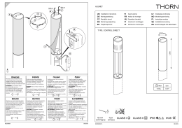
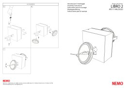
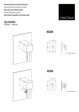
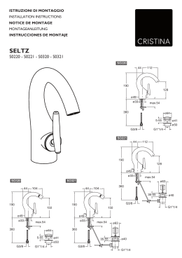
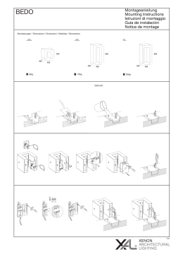
TriTec LED-Basic Manual
2b)Installation of recessed ring (*) for plasterboard ceilings
(also for premounted plasterboard panel, casing for
embedding in concrete and recessed installation ring
for timber ceilings):
- Press the leaf springs against the plastic casing and
insert in the ceiling. The perforated rim must be flush
with the plasterboard panel.
3a)Connection of operating device:
- Disconnect operating device from power supply.
Reconnect only when the luminaire is fully installed.
- The connection must be established with strain relief.
- The lines must not touch the luminaire casing.
- Connect the secondary cable separately to the
operating device (without luminaire).
- The positive terminal (red) of the secondary cable
must be connected to the positive terminal of the
operating device. The negative terminal (black) of the
secondary cable must be connected to the negative
terminal of the operating device (incorrect wiring can
cause damage to the luminaire).
3b)Insert the control device as shown in the diagram into
the recessed ring/frame.
4a)Connect the luminaire plug to the adapter of the operating unit.
4b)Engage the luminaire in the recessed ring/frame.
5) Align the spotlight as shown in the diagram.
6) Pull out the lens wall washer: Insert the Allen key in the
lens opening and pull the reflector together with the
socket unit from the recessed ring/frame.
Cleaning
Cleaning the luminaire: Clean the plastic parts with a soft
cloth and a conventional, neutral and non-abrasive detergent.
Cleaning the reflectors: When cleaning the reflectors, proceed with special care and use a soft cloth (microfibre
cleaning cloth), as the aluminium-vapour coated surfaces
are easily scratched.
Note
For safety reasons, damaged, exposed flexible cables of
this luminaire must be replaced by the manufacturer, an
authorised service agent or a suitably qualified electrician.
(*) Accessory
FR Informations générales
Lors du montage, observer les normes nationales
d’installation et de prévention des accidents ainsi que les
consignes relatives aux mesures de protection ESD.
Installation selon EN 60598
La distance latérale entre la délimitation du luminaire et les
parties du bâtiment doit être au moins égale à 50mm. Le
luminaire ne doit jamais être recouvert par un isolant thermique ou matériaux similaires.
HM06 14/09
Sélection appareil de fonctionnement (*) et volume
d’installation
-volume d’installation avec min 50 dm³ (par ex. 58 cm x
58 cm x 15 cm): max 700mA et 19W
- boîte pour béton standard (*) noyée dans le béton avec
un volume égal à 10 dm³: max 700mA et 19W
- boîtier à encastrer (boîte ignifuge) avec un volume min
égal à 12 dm³ (par ex. 29 cm x 29 cm x 15 cm): max
500mA et 13W
Montage (épaisseur plafond 1-30mm)
Pour éviter d’endommager et de salir le réflecteur, toucher
le lumin. uniquement à l’aide du gant fourni dans l’équipement.
1) Fente dans le plafond pour luminaires à bord visible:
- réaliser l’ouverture du plafond avec une tolérance de
+2 mm/0 mm
- la hauteur nominale de l’ouverture ronde dans le
plafond est de 95mm
- la hauteur nominale de l’ouverture carrée dans le
plafond est de 117mm
2a)Montage anneau/cadre d’installation à bord visible:
- appuyer sur les ressorts laminés contre le corps en
plastique et introduire dans l’ouverture du plafond
2b)Montage anneau d’installation (*) pour plafonds en
plâtre (ainsi que plaque en plâtre pré-montée, boîte
pour béton et anneau d’installation et montage pour
plafonds en bois):
-appuyer sur les ressorts laminés contre le corps en
plastique et introduire; le bord foré doit adhérer à la
plaque en plâtre
3a)Branchement appareil de fonctionnement:
- débrancher de l’alimentation de secteur, ne rebran
cher qu’après avoir terminé d’installer le luminaire
- décharger la traction du branchement
- les lignes ne doivent pas toucher le corps du luminaire
- brancher le câble secondaire (côté appareil d’instal lation) séparément (sans luminaire) à l’appareil
d’installation
- le pôle positif (rouge) du câble secondaire doit être
branché au pôle positif de l’appareil d’installation, le
pôle négatif (noir) du câble secondaire doit être
branché au pôle négatif de l’appareil d’installation (un
mauvais câblage peut endommager le luminaire)
3b)Introduire l’appareil d’installation selon la figure dans
l’anneau/cadre d’installation
4a) Brancher le connecteur du luminaire au connecteur de
fonctionnement
4b) Accrocher le luminaire dans l’anneau /cadre
d’installation
5) Orienter le spot de direction selon la figure
6) Extraire le wall washer avec verre: garder la clef pour
vis hexagonale creuse dans l’ouverture du verre et sortir
le réflecteur avec l’ensemble de la douille de l’anneau/
cadre d’installation
Entretien
Entretien du luminaire: l’entretien des parties en plastique
TriTec LED-Basic Manual
doit être effectué avec un chiffon souple et éventuellement
avec un produit nettoyant classique disponible dans le commerce, à pH neutre, non abrasif.
Entretien des réflecteurs: l’entretien des réflecteurs ayant
une surface vaporisée en aluminium, sensible aux rayures,
doit être effectué avec soin à l’aide exclusivement d’un
chiffon souple (en microfibre).
Conseil
Pour éviter tout danger, une ligne flexible, extérieure, endommagée, de ce luminaire peut être remplacée uniquement par
le fabricant, son représentant pour l’assistance ou par une
main d’œuvre spécialisée équivalente.
(*) Accessoires
IT Informazioni generali
Nel montaggio occorre osservare le prescrizioni nazionali di
installazione e prevenzione degli infortuni nonché le avvertenze relative alle misure di protezione ESD.
Installazione secondo EN 60598
La distanza laterale tra la delimitazione della lampada e le
parti dell’edificio deve essere pari a min. 50mm. La lampada
non può essere coperta, in alcun caso, da coperture ad
isolamento termico oppure da materiali simili.
Selezione apparecchio di esercizio (*) e volume di
installazione
- volume di installazione con min. 50dm³ (per es. 58cm x
58cm x 15cm): max. 700mA e 19W
- scatola per calcestruzzo standard (*) annegata nel calcestruzzo con un volume pari a 10dm³: max. 700mA e 19W
- custodia incassata (scatola ignifuga) con un volume min.
pari a 12dm³ (per es. 29cm x 29cm x 15cm):
max. 500mA e 13W
Montaggio (spessore soffitto 1-30mm)
Per evitare di danneggiare ed imbrattare il riflettore, toccare
la lampada solo con il guanto in dotazione.
1) Feritoia nel soffitto per lampade con bordo visibile:
- occorre realizzare l’apertura del soffitto con una
tolleranza pari a +2mm/0mm
- la quota nominale dell’apertura tonda nel soffitto è pari
a 95mm
- la quota nominale dell’apertura quadrata nel soffitto è
pari a 117mm
2a)Montaggio anello/cornice di installazione con bordo
visibile:
- premere le molle a lamina contro il corpo in plastica
ed inserire nell’apertura del soffitto
2b)Montaggio anello di installazione (*) per soffitti in gesso
(nonché lastra in gesso pre-montata, scatola per calcestruzzo e anello di installazione e montaggio per soffitti
in legno):
- premere le molle a lamina contro il corpo in plastica
HM06 14/09
ed inserire, il bordo forato deve aderire alla lastra in
cartongesso
3a)Allacciamento apparecchio di esercizio:
- staccare l’allacciamento dall’alimentazione di rete,
riallacciare solo dopo aver completato l’installazione
della lampada
- occorre scaricare la trazione dall’allacciamento
- le linee non devono toccare il corpo della lampada
- allacciare il cavo secondario (lato apparecchio di
esercizio) separatamente (senza lampada) all’appa recchio di esercizio
- il polo positivo (rosso) del cavo secondario deve
essere allacciato al polo positivo dell’apparecchio di
esercizio, il polo negativo (nero) del cavo secondario
deve essere allacciato al polo negativo dell’appa recchio di esercizio (il cablaggio errato può danneg giare la lampada)
3b)Inserire l’apparecchio di esercizio secondo la figura
nell’anello/cornice di installazione
4a)Allacciare il connettore della lampada al connettore
dell’apparecchio di esercizio
4b) Agganciare la lampada nell’anello/cornice di installazione
5) Orientare il faretto direzionale secondo la figura
6) Estrarre il wallwasher con lente: tenere la chiave per viti
ad esagono cavo nell’apertura della lente ed estrarre il
riflettore con l’unità porta-lampada dall’anello/cornice di
installazione
TriTec LED-Basic Manual
Downlight
HM06 14/09
1
2
3a
3b
4a
4b
(*)
Pulizia
Pulizia della lampada: La pulizia delle parti in plastica deve
essere eseguita con un panno morbido ed eventualmente
con un detergente comunemente disponibile in commercio,
con pH neutro, non abrasivo.
Pulizia dei riflettori: La pulizia dei riflettori con la superficie
vaporizzata in alluminio, sensibile ai graffi, deve essere
eseguita con cura esclusivamente con un panno morbido
(in microfibra).
Nota bene
Per evitare qualsiasi pericolo, una linea flessibile, esterna,
danneggiata, di questa lampada può essere sostituita
esclusivamente dal costruttore, il suo rappresentante per
l’assistenza oppure da manodopera specializzata, equivalente.
(*) Accessori
IP20
>50
>50
DE Die Produkte-Abbildungen und Beschreibungen entsprechen dem Stand zum Zeitpunkt der Drucklegung. Technische, formale oder massliche Änderungen sowie Irrtümer sind vorbehalten EN The product images and description correspond to the state at time of printing. Technical,
formal or dimensional information are subject to change FR Les illustrations et descriptifs correspondent aux spécifications en vigueur lors de
l‘impression. Des corrections techniques, formelles et dimensionnelles pourront être apportées ultérieurement IT Le figure dei prodotti e le descrizioni corrispondono allo stato al momento della stampa. Fatte salve eventuali modifiche tecniche, formali o dimensionali nonché eventuali errori.
TriTec LED-Basic Manual
Richtstrahler
Spotlight
Downlight orientable
Faretto direzionale
HM06 14/09
1
TriTec LED-Basic Manual
Linsenwandfluter
Lens wall washer
Downlight à faisceau mural
Wallwasher con lente
2
HM06 14/09
1
(*)
DE Allgemeine Informationen
Bei der Montage sind die nationalen Installations- und
Unfallverhütungsvorschriften, sowie die Warnhinweise ESDSchutzmassnahmen zu beachten.
2
Einbau nach EN 60598
Der seitliche Abstand zwischen der Leuchtenbegrenzung
und den Gebäudeteilen muss mindestens 50mm betragen.
Die Leuchte darf unter keinen Umständen durch wärmedämmende Abdeckungen oder ähnliche Werkstoffe abgedeckt
werden.
(*)
3a
4a
3b
3a
4b
4a
Auswahl Betriebsgerät (*) und Einbauvolumen
- Einbauvolumen mit Minimum 50dm3
(z.B. 58cm x 58cm x 15cm): max. 700mA und 19W
- Einbetoniertes Standard-Einbetoniergehäuse (*) mit
Volumen von 10dm3: max. 700mA und 19W
- Einbaugehäuse (Flammbox) mit Minimum 12dm3 Volumen
(z.B. 29cm x 29cm x 15cm): max. 500mA und 13W
3b
4b
6
5
IP20
>50
IP20
>50
DE Die Produkte-Abbildungen und Beschreibungen entsprechen dem Stand zum Zeitpunkt der Drucklegung. Technische, formale oder massliche Änderungen sowie Irrtümer sind vorbehalten EN The product images and description correspond to the state at time of printing. Technical,
formal or dimensional information are subject to change FR Les illustrations et descriptifs correspondent aux spécifications en vigueur lors de
l‘impression. Des corrections techniques, formelles et dimensionnelles pourront être apportées ultérieurement IT Le figure dei prodotti e le descrizioni corrispondono allo stato al momento della stampa. Fatte salve eventuali modifiche tecniche, formali o dimensionali nonché eventuali errori.
TriTec LED-Basic Manual
>50
>50
DE Die Produkte-Abbildungen und Beschreibungen entsprechen dem Stand zum Zeitpunkt der Drucklegung. Technische, formale oder massliche Änderungen sowie Irrtümer sind vorbehalten EN The product images and description correspond to the state at time of printing. Technical,
formal or dimensional information are subject to change FR Les illustrations et descriptifs correspondent aux spécifications en vigueur lors de
l‘impression. Des corrections techniques, formelles et dimensionnelles pourront être apportées ultérieurement IT Le figure dei prodotti e le descrizioni corrispondono allo stato al momento della stampa. Fatte salve eventuali modifiche tecniche, formali o dimensionali nonché eventuali errori.
Montage (Deckenstärke 1-30mm)
Um Beschädigungen und Verschmutzungen des Reflektors
zu vermeiden, Leuchte nur mit beiliegendem Handschuh
anfassen.
1) Deckenausschnitt für Leuchten mit Sichtrand:
-Deckenöffnung ist mit einer Toleranz von +2mm/0mm
herzustellen
- Nennmass der runden Deckenöffnung 95mm
- Nennmass der quadratischen Deckenöffnung 117mm
2a)Montage Einbauring-/rahmen mit Sichtrand:
- Blattfedern an das Kunststoffgehäuse andrücken und
in die Deckenöffnung einsetzen
2b)Montage Einbauring (*) für Gipsdecken (sowie vormontierte Gipsplatte, Einbetoniergehäuse und EinbauMontagering für Holzdecken):
- Blattfedern an das Kunststoffgehäuse andrücken
und einsetzen, Lochrand soll an der Gipskartonplatte
anliegen
3a)Anschluss Betriebsgerät:
- Anschluss von der Netzversorgung trennen, erst nach
beendetem Leuchteneinbau wieder anschliessen
- Anschluss muss zugentlastet werden
- Leitungen dürfen Leuchtengehäuse nicht berühren
-Sekundärkabel (Seite Betriebsgerät) s eparat (ohne
Leuchte) an das Betriebsgerät anschliessen
- Pluspol (rot) des Sekundärkabels soll an den Pluspol
des Betriebsgerätes angeschlossen sein, Minuspol
(schwarz) des Sekundärkabels soll an den Minuspol
des Betriebsgerätes angeschlossen sein (bei falscher
Verkabelung kann die Leuchte Schaden nehmen)
3b)Betriebsgerät gemäss Abbildung in Einbauring-/rahmen
einführen
4a)Leuchtenstecker an Stecker des Betriebsgerätes
anschliessen
4b)Leuchte in Einbauring-/rahmen einrasten
5) Richtstrahler gemäss Abbildung ausrichten
HM06 14/09
6) Linsenwandfluter herausziehen: Inbusschlüssel
in die Öffnung der Linse halten und Reflektor mit
Fassungseinheit aus dem Einbauring/-rahmen ziehen.
Reinigung
Reinigung der Leuchte: Die Reinigung der Kunststoffteile
ist mit einem weichen Tuch und ggf. mit einem handelsüblichen, pH-neutralen, nicht scheuernden Reinigungsmittel
vorzunehmen.
Reinigung der Reflektoren: Die Reinigung der Reflektoren
mit der kratzempfindlichen aluminiumbedampften Oberfläche
ist vorsichtig und ausschliesslich mit einem weichen Tuch
(Mikrofasertuch) vorzunehmen.
Hinweis
Zur Vermeidung von Gefährdungen darf eine beschädigte,
äussere, flexible Leitung dieser Leuchte ausschliesslich vom
Hersteller, seinem Servicevertreter oder einer vergleichbaren
Fachkraft ausgetauscht werden.
(*) Zubehör
EN General information
For installation, observe the statutory installation and safety
regulations and the warnings regarding electrostatic
discharge.
Installation according to EN 60598
The lateral distance between the luminaire casing and the
building structure must be minimum 50mm. Never cover the
luminaire with thermal insulation or similar materials.
Selection of operating device (*) and installation space
requirements
- Minimum installation space: minimum 50dm3
(e.g. 58cm x 58cm x 15cm): max. 700mA and 19W
- Standard casing (*) for embedding in concrete, size
10dm3: max. 700mA and 19W
- Flame box casing, minimum installation size 12dm3
(e.g. 29cm x 29cm x 15cm): max. 500mA and 13W
Installation (thickness of ceiling 1-30mm)
To prevent damage and dirt on the reflector, do not touch the
luminaire with your bare hands. Always wear the enclosed
glove.
1) Opening in ceiling for luminaire with visible rim:
- Produce a ceiling opening with a tolerance of
+2mm/0mm.
- Nominal dimension for round ceiling opening: 95mm
- Nominal dimension for square ceiling opening:
117mm
2a) Installation of recessed ring/frame with visible rim:
- Press the leaf springs against the plastic casing and
insert the casing in the ceiling opening.
Scaricare