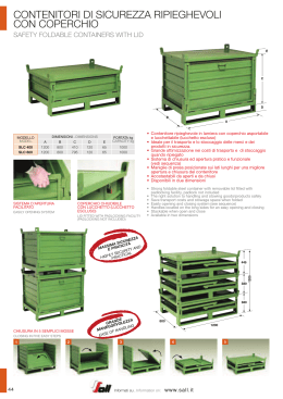
ITALIANO
PCM100
Centrale di automazione a 230V
per cancello scorrevole
MANUALE UTENTE
Per circuiti stampati 425ama-2.00
Made in Italy
EMC 89/336 CEE
PCM100 - Manuale per l'utente
Norme generali per la sicurezza
!
!
!
!
!
!
!
!
!
!
!
!
!
Leggere attentamente le istruzioni prima di iniziare I'installazione del prodotto e conservarle per riferimenti futuri.
Installazione, collegamenti elettrici e regolazioni devono essere effettuati nell'osservanza delle norme di buona
tecnica e di sicurezza vigenti (UNI 8612).
HILTRON Srl non è responsabile dell'inosservanza della buona tecnica nella costruzione dei cancelli da motorizzare,
nonchè delle deformazioni che dovessero intervenire nell'utilizzo.
Prima d'installare I'automazione apportare tutte le modifiche strutturali relative alla realizzazione dei franchi di
sicurezza ed alla protezione e/o segregazione di tutte le zone di cesoiamento, convogliamento e schiacciamento.
Questo prodotto è stato progettato e costruito esclusivamente' per I'utilizzo indicato in questa documentazione.
Qualsiasi altro utilizzo non espressamente indicato potrebbe pregiudicare I'integrità del prodotto e/o rappresentare
fonte di pericolo.
HILTRON Srl declina qualsiasi responsabilità derivata dall'uso improprio o diverso da quello per cui I'automatismo è
destinato.
Non utilizzare I'apparecchio in atmosfera esplosiva: presenza di gas o fumi infiammabili costituiscono un grave
pericolo per la sicurezza.
Prima di effettuare qualsiasi intervento sull'impianto togliere I'alimentazione elettrica.
Prevedere sulla rete d'alimentazione dell'automazione un interruttore onnipolare con distanza d'apertura dei contatti
uguale o superiore a 3 mm. In alternativa e consigliabile I'uso di un magnetotermico da 6A con interruzione
onnipolare.
Verificare che a monte dell'impianto elettrico vi sia un interruttore differenziale con soglia da 0,03 A.
Verificare che I'impianto di terra sia realizzato a regola d'arte e collegarvi iI cancello. Collegare inoltre a terra il filo
Giallo/Verde dell'automatismo.
L'utente utilizzatore deve astenersi da qualsiasi tentativo di riparazione o d'intervento diretto e rivolgersi solo a
personale qualificato.
Per la manutenzione utilizzare esclusivamente parti originali CIA della HILTRON Srl. Non eseguire alcuna rnodifica
sui cornponenti facenti parte il sistema
d'autornazione. I materiali dell'imballaggio
®
(plastica, cartone, ecc.) non devono essere
lasciati alla portata dei bambini in quanto
potenziali fonti di pericolo.
L'installatore deve fornire tutte le informazioni
DICHIARAZIONE
DI CONFORMITA’
relative al funzionamento manuale del
SECONDO LE NORME ISO/IEC GUIDA 22 EN 45014
sistema in caso d'emergenza e consegnare
all'utente utilizzatore dell'impianto il presente
COSTRUTTORE: HiLTRON S.r.l.
libretto d'avvertenze allegato al prodotto.
INDIRIZZO: Via Caserta al Bravo, 218 Napoli
L'automazione dispone di una sicurezza
MARCHIO UTILIZZATO:
antischiacciamento costituita da un controllo
di coppia che, se tarato correttamente, è
CODICE PRODOTTO: PCM100
estremamente sicuro ed affidabile.
DESCRIZIONE DEL PRODOTTO: CENTRALE DI AUTOMAZIONE PER CANCELLO
In ogni caso HILTRON Srl prescrive sempre
SCORREVOLE
I'installazione di altri dispositivi di sicurezza,
Il prodotto sopra descritto risulta conforme ai requisiti prescritti nelle seguenti norme:
tenendo in considerazione le normative in
vigore, I'ambiente di installazione, la logica di
NORMA APPLICATA
TITOLO
funzionamento del sisterna, le dimensioni e il
EN50081-1 (1992)
NORMA GENERICA DI EMISSIONE
peso della struttura da automatizzare.
Classe della norma generica: domestico,
I dispositivi di sicurezza (es.: fotocellule,
commerciale ed industriale leggero.
coste pneumatiche, etc...) permettono di
EN50082-1 (1992)
NORMA GENERICA DI IMMUNITA’
proteggere eventuali zone di schiacciamento,
Classe della norma generica: domestico,
convogliamento ed in generale di pericolo,
commerciale ed industriale leggero.
dell'automazione. Per ogni irnpianto è
EN60335-1 (1996)
NORMA PER LA SICUREZZA DEGLI
indispensabile I'utilizzo di almeno una
APPARECCHI ELETTRICI D'USO
DOMESTICO E SIMILARE
segnalazione luminosa (es.: art. LAMP230G
CIA) nonchè di una targa di segnalazione
La conformita' e' stata valutata sulla base di prove eseguite su campione e con allestimento che
(es.: art. TRG CIA) fissato adeguatamente
rispecchia la configurazione funzionale prevista per la sua utilizzazione allestita interamente con
prodotti CIA di produzione HiLTRON S.r.l. .
alla struttura del cancello.
Pertanto il prodotto soddisfa i requisiti della direttiva EMC 89/336/CEE e BT 73/23/CEE.
HILTRON Srl declina ogni responsabilità ai
Napoli, 17 Marzo 1999
fini della sicurezza e del buon funzionamento
dell'automazione nel caso in cui vengano
L’ AMMINISTRATORE DELEGATO
utilizzati componenti dell'impianto diversi da
quelli CIA (prodotti da HILTRON Srl).
PROGETTAZIONI E PRODUZIONI ELETTRONICHE
!
!
!
!
!
2
Introduzione
Indice
Capitolo 1
Introduzione
4
1.1 Descrizione della centrale .................................................................................4
1.2 Caratteristiche funzionali...................................................................................4
1.3 Caratteristiche tecniche.....................................................................................4
Capitolo 2
Installazione
5
2.1 Descrizione della scheda ..................................................................................5
2.2 Esempio d'installazione dell’impianto................................................................6
2.3 Collegamenti .....................................................................................................8
2.3.1 Rete di alimentazione, lampeggiatore, motoriduttore, comandi.............8
2.3.2 Fotocellule a relè ...................................................................................9
2.3.3 Fotocellule con autodiagnosi .................................................................9
Capitolo 3
Programmazione
10
3.1 Dip-switch........................................................................................................10
3.1.1 Funzionamento AUTOMATICO CONDOMINIALE ...............................11
3.1.2 Funzionamento AUTOMATICO............................................................11
3.1.3 Funzionamento PASSO-PASSO CON RICHIUSURA AUTOMAT........12
3.1.4 Funzionamento PASSO-PASSO MANUALE CON STOP ...................12
3.2 Regolazione frizione elettronica (trimmer A) ...................................................13
3.3 Regolazione tempo di pausa (trimmer B)........................................................13
3.4 Freno elettronico / Rallentamento (trimmer C)................................................13
3.5 LEDs di controllo .............................................................................................13
3.6 Programmazione del ricevitore per radiocomando .........................................14
3.7 Programmazione del radiocomando ...............................................................15
Capitolo 4
Manutenzione
16
4.1 Cancello ..........................................................................................................16
4.2 Fusibili .............................................................................................................16
3
PCM100 - Manuale per l'utente
1
Introduzione
1.1
Descrizione della centrale
La PCM100 è una centrale di automazione per cancelli scorrevoli. Essa gestisce un
motoriduttore a 230Vca 700VA max, tipo MS100 o MS200 prodotti dalla CIA. La gestione
avviene tramite frizione elettronica, realizzata con un microprocessore di nuova generazione.
La PCM100 è dotata di un sofisticato circuito di auto-diagnostica che sorveglia costantemente
il corretto funzionamento dell’impianto e delle apparecchiature collegate; in caso di anomalie
tale circuito interviene bloccando il funzionamento della centrale. Il monitoraggio del
funzionamento delle apparecchiature periferiche collegate alla centrale è visualizzato tramite
LED posti sul circuito. Inoltre la PCM100 è dotata di freno elettronico che controlla in maniera
lineare l’arresto del motoriduttore. In alternativa al freno interviene la funzione di rallentamento
3 secondi prima dell’intervento del finecorsa, sia in fase di apertura che di chiusura,
consentendo al cancello di rispettare sempre il punto di arrivo evitando inutili urti.
La PCM100 è conforme alle direttive EMC 89/336 e 73/23 CEE, per cui riporta la
marchiatura CE.
1.2
!
!
!
!
!
!
!
!
!
!
!
!
!
1.3
!
!
!
!
!
!
!
!
4
Caratteristiche funzionali
Funzione “RALLENTAMENTO” con trimmer “FRENO” al minimo.
Funzione “FRENO” regolabile mediante trimmer con esclusione al minimo.
Logiche ed opzioni di funzionamento programmabili: Automatica condominiale, passo passo con
richiusura automatica, passo passo con STOP.
Interfaccia per ricevitore BIRD integrata.
Regolazione di COPPIA tramite trimmer.
Auto-diagnostica del funzionamento.
Monitoraggio tramite diodi LED dello stato delle apparecchiature periferiche.
Trimmer di regolazione: “FRENO”, PAUSA”, “FORZA DI SPINTA!”.
Ingresso comando Apertura Totale.
Ingresso comando Apertura Parziale.
Ingresso comando STOP.
2 ingressi configurabili per fotocellule tipo IR-SYSTEM con AUTODIAGNOSI.
Contenitore in ABS - IP44.
Caratteristiche tecniche
Tensione nominale di alimentazione: 230V~ ±10% 50Hz
Consumo della centrale: 10W max (a motore spento)
Tensione nominale in uscita periferiche: 24V~ ±5% max 0,1A
Tempo apertura/chiusura: max 90 secondi
Tempo di pausa: 4 ÷ 60sec.
Temperatura di funzionamento: -25ºC ÷ 55ºC
Dimensioni box esterno (LxAxP): 127x138x57mm
Dimensioni scheda (LxA): 98x118mm
Installazione
2
Installazione
2.1
Descrizione della scheda
3
2
4
14
15
8
7
6
5
12
11
10
1
21
16
9
13
18
17
19
20
1
Fusibile rete (250Vac 3,15A)
12
LED stato finecorsa di chiusura
2
Trimmer A: frizione elettronica
13
LED stato STOP
3
Trimmer B: durata pausa
14
LED diagnostica microprocessore
4
Trimmer C: freno elettronico / rallentamento
15
Dip-Switch di programmazione
5
P1: apertura totale
16
6
P2: apertura parziale
Connettore finecorsa, da usare se la centrale
viene installata nel motore
17
LED Pulsante P1
Morsetti alimentazione 230Vca
7
18
LED Pulsante P2
Morsetti lampeggiatore e motore
8
19
LED stato fotocellula 1
Morsetti BIRD e comandi
9
20
LED stato fotocellula 2
Morsetti fotocellule e uscita 24Vca
10
21
11
LED stato finecorsa di apertura
Morsetti finecorsa, da usare se la centrale
viene installata esternamente al motore
autoapprendimento
codice radiocomando
5
PCM100 - Manuale per l'utente
2.2
Esempio d'installazione
6
2
5
4
1
8
9
1
MS100 + PCM100 + FCMS
2
FX30 / FX40 / FX55 (TX)
FX30 / FX40 / FX55 (RX)
FX30 / FX40 / FX55 (TX)
FX30 / FX40 / FX55 (RX)
LAMP230G
BIRD
SC1
FCMM
FCMM
CRP
3
4
5
6
7
8
9
10
11
7
3
11
10
Motoriduttore MS100 con centrale PCM100 e
sensore per finecorsa magnetici FCMS
Fotocellula trasmittente 1
Fotocellula ricevente 1
Fotocellula trasmittente 2
Fotocellula ricevente 2
Lampeggiatore elettronico 230Vca
Ricevitore VHF con antenna
Selettore a chiave
Finecorsa magnetico di apertura
Finecorsa magnetico di chiusura
Cremagliera in plastica
E’ possibile installare la centrale direttamente nel motore MS100 utilizzando il perno in
dotazione, o a muro fissandola con due tasselli.
In entrambi i casi, è necessario fissare il coperchio alla base con la vite in dotazione con la
centrale.
FCMS
Sensore
finecorsa
Perno in
dotazione
Centrale PCM100 installata
all’interno del motore MS100
6
Centrale PCM100 installata a muro
Installazione
2.3
Connessioni
22
21
20
Connettore
finecorsa
1
2
3
4
5
6
7
8
9 10 11 12 13 14 15 16 17 18 19
Usare questo connettore per collegare
il cavetto del finecorsa nel caso in cui la
scheda elettronica sia montata
all'interno del motore.
NOTA: Se fosse necessario
invertire i fili del finecorsa, invertire
i magneti 9 e 10 a pagina 6.
1 - L1
2 - Terra
3-N
RETE DI ALIMENTAZIONE 230V~ ±10% 50Hz
4 - Polo 1
5 - Polo 2
6 - Chiusura
7 - Comune (filo blu)
8 - Apertura
LAMPEGGIATORE 230V~
9 - Polo 1(mors. 1 BIRD)
10 - Polo 2(mors. 2 BIRD)
ANTENNA BIRD
11 - Comune
12 - Impulso STOP (NC)
13 - Impulso A (NA)
14 - Impulso B (NA)
COMANDI
15 - NC
16 - Comune
17 - NC
18 - 24V~ max 100mA
19 - 24V~ max 100mA
FOTOCELLULE
(FX30 - FX40 - FX55)
20 - Finecorsa di apertura
21 - Comune finecorsa
22 - Finecorsa di chiusura
FINECORSA
Usare questa morsettiera nel caso in cui la scheda elettronica sia installata all'esterno del
motore.
MOTORIDUTTORE
230V~ 700W max
7
PCM100 - Manuale per l'utente
3x1,5mm
LAMP230G
( 6 pagina 6)
N
Terra
3x1,5mm
L1
2x1mm
Rete di alimentazione, lampeggiatore, motoriduttore, comandi
2x1mm
2.3.1
RETE DI
ALIMENTAZIONE
230V~ ±10% 50Hz
Apertura
parziale
2B
Apertura
totale
Pulsanti di comando
opzionali (da citofono, etc.)
ATTENZIONE: utilizzare un
cavo schermato a due
conduttori, tipo 2S, dedicato
al collegamento del solo
ricevitore BIRD rispettando
la polarità in fase di
collegamento.. Non
utilizzare due conduttori
liberi di cavi già utilizzati per
altre periferiche.
LAMP230G
( 6 pagina 6)
Lampeggiatore
230V~
MS100
( 1 pagina 6)
230V~ 700W max
STOP
NC
NA
4S
SC1 (
8
APRE
CHIUDE
pagina 6)
Chiusura
Comune (blu)
Apertura
N.A.
8
Timer
Per lasciare il cancello aperto in un certo orario (es. 7:00
÷ 8:30 del mattino), è possibile collegare un timer come
mostrato sopra (par.3.2.1).
All’ attivazione del timer (commutazione contatto
da N.A. a N.C.), il cancello eseguirà un ciclo di apertura e
resterà aperto fino a quando il contatto timer è N.C.
Installazione
2.3.2
DIP1
Fotocellule a relè (FX40, FX55)
ON
5
3 4
2
2
( 3 pagina 6)
5
3 4
(
5
pagina 6)
JMP2
1
2
2
1
( 4 pagina 6)
JMP2
C NA NC
JMP2
1
1
( 2 pagina 6)
JMP2
C NA NC
SW4=OFF
2.3.3
DIP1
Fotocellule con autodiagnosi (FX30)
ON
1
2
2
1
1
( 4 pagina 6)
2
( 2 pagina 6)
1
2
SW4=ON
( 3 pagina 6)
(
5
pagina 6)
NOTA: Installando le FX30 è obbligatorio montare due coppie di fotocellule.
9
PCM100 - Manuale per l'utente
3
Programmazione
3.1
Dip-switch
La logica di funzionamento e le varie opzioni vengono settate tramite gli switch 1, 2 e 3 del
dip-switch presente sulla scheda ( 15 a pagina 5). Lo switch 4 serve invece a settare il tipo di
fotocellula installato (vedi pagina precedente). Ecco un riepilogo dei possibili settaggi:
ON
Funzionamento Automatico
Condominiale
OFF OFF
Funzionamento Automatico
ON
OFF
Funzionamento passo/passo
con richiusura automatica
OFF
ON
Funzionamento passo/passo
con STOP
ON
ON
Blocco abilitato
ON
Blocco disabilitato
OFF
FX30 (autodiagnosi)
ON
FX40 - FX55
OFF
ON
Switch 1 e 2:
Funzionamento
ON
ON
ON
Switch 3:
Blocco
apertura su
interruzione
fotocellule
ON
ON
SWITCH 4:
Tipo di
fotocellula
installata
ON
Per conoscere le logiche di funzionamento vedi paragrafo successivo.
ATTENZIONE: Il settaggio dei DIP- SWITCH va fatto a centrale spenta.
10
Programmazione
3.1.1
Funzionamento AUTOMATICO condominiale
(SW1=OFF - SW2=OFF)
Ad un impulso esegue: apertura , pausa , richiusura automatica .
Durante la fase di apertura vengono ignorati eventuali impulsi. Durante la fase di chiusura,
eventuali impulsi, arrestano ed invertono immediatamente il movimento del cancello .
Un contatto fisso chiuso su IMPULSO A ( funzione orologio ) apre il cancello fino alla pausa e
lascia il cancello aperto sino alla riapertura del contatto.
STATO DEL
CANCELLO
IMPULSO A
IMPULSO B
STOP
CHIUSO
Apertura totale e
richiusura dopo il
tempo di pausa
Apertura parziale e
richiusura dopo il
tempo di pausa
Ignora gli impulsi A e B
impedendo l’aperura
IN
APERTURA
APERTURA
PARZIALE
IN PAUSA
APERTURA
TOTALE
IN PAUSA
ON
FOTOCELL. 1
FOTOCELL. 2
Vedi SWITCH 3 pagine 9 e 10
Nessun effetto se il
ciclo apri è iniziato con
L’IMPULSO A
Apertura totale se il
ciclo apri è iniziato con
L’IMPULSO B
Apertura totale
Nessun Effetto
Nessun Effetto
Impedisce la richiusura
ed alla fine della pausa
reintegra ulteriori 5
secondi sino al ripristino
Blocca
funzionamento e
va in STOP
Impedisce la richiusura ed alla fine della pausa
reintegra ulteriori 5 secondi sino al ripristino.
Non impedisce l’eventuale apertura totale.
Impedisce la richiusura ed alla fine della pausa
reintegra ulteriori 5 secondi sino al ripristino
Impedisce la richiusura ed alla fine della pausa
reintegra ulteriori 5 secondi sino al ripristino
IN CHIUSURA
Si arresta e riapre immediatamente
Blocca il funzionamento e riapre il cancello
immediatamente
IN STOP
Riprende la funzione che era in esecuzione
prima dello STOP ( chiusura o apertura )
3.1.2
Ignora impulsi A e B
impedendo la riapertura o la richiusura
Funzionamento AUTOMATICO ( SW1=ON - SW2=OFF)
ON
Ad un impulso esegue: apertura, pausa, richiusura automatica .
Durante la fase di apertura o chiusura , eventuali impulsi , arrestano ed invertono
immediatamente il movimento del cancello .
Durante la fase di pausa, eventuali impulsi richiudono immediatamente il cancello.
STATO DEL
CANCELLO
IMPULSO A
IMPULSO B
STOP
CHIUSO
Apertura totale e
richiusura dopo il
tempo di pausa
Apertura parziale e
richiusura dopo il
tempo di pausa
Ignora gli impulsi A e B
impedendo l’aperura
IN
APERTURA
Si arresta e richiude immediatamente
APERTO IN
PAUSA
Richiude il cancello immediatamente
IN CHIUSURA
Si arresta e riapre immediatamente
IN STOP
Riprende la funzione che era in esecuzione
prima dello STOP ( chiusura o apertura )
FOTOCELL. 1
FOTOCELL. 2
Vedi SWITCH 3 pagine 9 e 10
Nessun Effetto
Blocca
funzionamento e
va in STOP
Impedisce la richiusura ed alla fine della pausa
reintegra ulteriori 5 secondi sino al ripristino
Blocca il funzionamento e riapre il cancello
immediatamente
Ignora impulsi A e B
impedendo la riapertura o la richiusura
11
PCM100 - Manuale per l'utente
3.1.3
Funzionam. PASSO-PASSO CON RICHIUSURA AUTOMAT. (SW1=OFF- SW2=ON)
ON
Un impulso esegue : apertura , pausa , richiusura automatica .
Durante la fase di apertura o chiusura , eventuali impulsi , arrestano il cancello portandolo nella
condizione di STOP .
Durante la fase di pausa , eventuali impulsi richiudono immediatamente il cancello .
STATO DEL
CANCELLO
IMPULSO A
IMPULSO B
STOP
CHIUSO
Apertura totale e
richiusura dopo il
tempo di pausa
Apertura parziale e
richiusura dopo il
tempo di pausa
Ignora gli impulsi A e B
impedendo l’aperura
IN
APERTURA
Si arresta e solo ad un successivo impulso
richiude
APERTO IN
PAUSA
Richiude il cancello immediatamente
IN CHIUSURA
Si arresta e solo ad un successivo impulso
riapre
IN STOP
Riprende la funzione che era in esecuzione
prima dello STOP ( chiusura o apertura )
3.1.4
FOTOCELL. 1
FOTOCELL. 2
Vedi SWITCH 3 pagine 9 e 10
Nessun Effetto
Blocca
funzionamento e
va in STOP
Impedisce la richiusura ed alla fine della pausa
reintegra ulteriori 5 secondi sino al ripristino
Blocca il funzionamento e riapre il cancello
immediatamente
Ignora impulsi A e B
impedendo la riapertura o la richiusura
Funzionam. PASSO-PASSO MANUALE CON STOP (SW1=ON - SW2=ON)
ON
Un impulso apre ; l'impulso successivo arresta ; l'impulso successivo chiude ; l'impulso
successivo si arresta ; l'impulso successivo apre e così via .
DIP1
STATO DEL
CANCELLO
IMPULSO A
CHIUSO
Apertura totale con
arresto al termine
IMPULSO B
Apertura parziale con Ignora gli impulsi A e B
impedendo l’aperura
arresto al termine
IN
APERTURA
Si arresta e solo ad un successivo impulso
richiude
ARRESTO
Inverte il movimento del motore
IN CHIUSURA
Si arresta e solo ad un successivo impulso
riapre
IN STOP
Riprende la funzione che era in esecuzione
prima dello STOP ( chiusura o apertura )
12
FOTOCELL. 1
STOP
FOTOCELL. 2
Vedi SWITCH 3 pagine 9 e 10
Nessun Effetto
Blocca
funzionamento e
va in STOP
Ignora impulsi A e B bloccando ogni movimento
Blocca il funzionamento e riapre il cancello
immediatamente
Ignora impulsi A e B
impedendo la riapertura o la richiusura
Programmazione
3.2
Regolazione della frizione elettronica (trimmer A)
Tale regolazione agisce sulla forza di spinta del motoriduttore: essa deve essere in
grado di provocare lo spostamento del cancello, e ciò è dipendente dal suo peso.
Durante il suo movimento, anche il cancello acquisisce, a sua volta, una forza di spinta.
Secondo le disposizioni di legge, la regolazione va effettuata in modo tale che la forza di
spinta del cancello non deve superare 15Kg; ciò vuol dire che una forza di 15Kg opposta al
movimento del cancello lo deve bloccare durante il suo movimento.
Per effettuare tale regolazione è consigliabile utilizzare un dinamometro lineare.
3.3
Regolazione del tempo di pausa (trimmer B)
Se la centrale è stata programmata in Funzionamento automatico condominiale o
Funzionamento automatico è necessario regolare il tempo di pausa che intercorre tra il
termine dell'apertura e l’inizio della chiusura del cancello.
3.4
Regolazione Freno elettronico / Rallentamento (trimmer C)
Con trimmer girato in senso antiorario:
Freno elettronico:
disattivo
Rallentamento:
attivo prima del termine dell'apertura/chiusura
Con trimmer girato in senso orario:
Freno elettronico:
attivo, riduce lo spazio di avanzamento del cancello dopo
l'intervento del finecorsa
Rallentamento:
disattivo
3.5
LEDs di controllo
Di seguito è riporto il significato dei LEDs presenti sulla scheda (vedi pagina 5):
LED
COLORE
LAMPEGGIANTE
SPENTO
/
A riposo
verde
ACCESO
Impulso su ingresso A
(apertura totale)
Impulso su ingresso B
(apertura parziale)
7
verde
8
/
A riposo
9
rosso
A riposo
/
Fotocellula 1 impegnata
10
rosso
A riposo
/
Fotocellula 2 impegnata
11
rosso
A riposo
/
12
rosso
A riposo
/
Finecorsa di apertura
impegnato
Finecorsa di chiusura
impegnato
13
giallo
A riposo
/
Comando STOP attivo
14
verde
Anomalia
Funzionamento normale
Anomalia
13
PCM100 - Manuale per l'utente
3.6
Programmazione del ricevitore per radiocomando
Visualizzazione del codice programmato
!
!
!
Premere contemporaneamente i pulsanti P1-P2 ( 5 e 6 in figura 1) per almeno 2 secondi e
non più di 5 secondi, finchè i due LED ( 7 e 8 in figura 1) si accenderanno fissi
Premendo il pulsante P1 verrà visualizzato il codice a 12 bit del canale "A" tramite una
sequenza di lampeggi dei due LEDs:
!
un lampeggio del LED 7 indica dip switch ON
!
un lampeggio del LED 8 indica dip switch OFF
Terminata la sequenza si uscirà automaticamente dalla fase di programmazione.
NOTA: Se nessun tasto viene attivato nell’arco di 5 secondi, la procedura ha termine senza
visualizzare alcun codice.
NOTA: Per visualizzare il codice del canale "B", ripetere la procedura utilizzando il pulsante
P2.
Acquisizione con auto-apprendimento del codice del telecomando
!
!
!
!
Premere contemporaneamente i pulsanti P1-P2 ( 5 e 6 a pagina 5) per almeno 5 secondi e
rilasciare quando i due LED ( 7 e 8 a pagina 5) iniziano a lampeggiare.
Premere il pulsante P1, lampeggerà solo il 7 .
Durante il lampeggio, premere entro 5 secondi il pulsante "A" del telecomando per fare
acquisire il codice.
Il LED 7 emetterà una serie di lampeggi per indicare l'avvenuta acquisizione e si uscirà
automaticamente dalla fase di programmazione
NOTA: Se nessun radiocomando viene attivato nell’arco di 10 secondi, la procedura ha
termine senza programmare alcun codice.
NOTA: Per far acquisire il codice del canale "B" del telecomando, ripetere la procedura,
utilizzando il pulsante P2 ed il LED 8 .
Riepilogo dei tempi di accesso al setup
Tempo di pressione contemporanea dei pulsanti P1 e P2:
0 sec.
14
2 sec.
5 sec.
Stato dei LED
LED “1” e “2”
spenti
LED “1” e “2”
accesi fissi
LED “1” e “2”
lampeggianti
Funzione
Nessun effetto.
Rilasciando P1 e P2, si
entrerà in modalità di
visualizzazione del
codice.
Rilasciando P1 e P2, si
entrerà in modalità
autoapprendimento del
codice.
Programmazione
2.7
Programmazione del radiocomando
Il TWIN permette la programmazione indipendente per ognuno dei 2 tasti; è infatti possibile
memorizzare su ogni tasto un codice diverso, ed un canale a scelta (A oppure B).
La programmazione deve essere ripetuta quindi per ognuno dei 2 tasti del radiocomando.
Per accedere alla programmazione del radiocomando premere entrambi i tasti per alcuni secondi,
finché il LED rimane acceso, poi rilasciarli;a questo punto sono disponibili 2 prodecure:
MEMORIZZAZIONE
NOTA:durante la programmazione, se non si preme alcun tasto per almeno 5 secondi il LED si
spegne e la fase di programmazione termina autOmaticamente
Per accedere all'inserimento del codice digitare la sequenza di tasti "1" - "1" - "0" - "0"
!
Inserire le 10 cifre del codice utilizzando:
? “0” (tasto destro): ossia dip-switch "OFF" sulle versioni TWIN
precedenti*
? “1” (tasto sinistro): ossia dip-switch "ON" sulle versioni TWIN
precedenti*
!
Ad ogni inserimento il LED si spegnerà per un istante.
!
Inserire le 2 cifre del canale:
? Canale A "1" - "0": ossia tasto sinistro sulle versioni TWIN precedenti
? Canale B "1" - "1": ossia tasto destro sulle versioni TWIN precedenti
!
Premere il pulsante a cui assegnare il codice appena inserito (A oppure B).
!
Il LED si spegne alla fine della programmazione.
+
*
Ad esempio, per programmare un codice o duplicare un TWIN di precedente versione che abbia i dipswitch così impostati:
ON
OFF
1
2
3
4
5
6
7
8
9
10
è necessario digitare la seguente sequenza di tasti:
1 1 0 0
accesso
1 0 0 1 1 0 1 0 0 1
codice
1 0 (lamp. veloce del LED) 1
canale A
assegn. al tasto sinistro
1 1 0 0
accesso
1 0 0 1 1 0 1 0 0 1
codice
1 1 (lamp. veloce del LED) 0
canale B
assegn. al tasto destro
VISUALIZZAZIONE
Per leggere il codice programmato:
Entrare in programmazione tenendo premuti i due tasti per alcuni secondi finchè il led rimane
acceso e digitare la sequenza di tasti "1" - "0" - "1" - "0"
! Premere il tasto di cui si desidera conoscere il codice (A oppure B)
! Il LED si spegne e poi comincia ad emettere una serie di dodici lampeggìi:
? un lampeggìo breve indica "0"
? un lampeggìo lungo indica "1”
!
SOSTITUZIONE BATTERIA
Svitare la vite posta sul fondo del telecomando per aprire il contenitore, togliere la vecchia batteria ed
inserirne una nuova rispettando le polarità indicate sul contenitore.
Controllare il corretto funzionamento dei due tasti prima di richiudere il contenitore.
15
PCM100 - Manuale per l'utente
4
Manutenzione
4.1
Cancello
Eseguire controlli periodici sulla struttura del cancello ed in particolare verificare la
perfetta condizione dei carrelli, della cremagliera e delle altre parti meccaniche soggette ad
usura.
4.2
F1
Fusibili
3,15A 250V
Fusibile RETE
EMC 89/336 CEE
MADE IN ITALY
Azienda con Sistema di
gestione per la Qualità
UNI EN ISO 9001:2000
16
Azienda con Sistema di
g estio n e a mb ie n tale
UNI EN ISO 14001:2004
Il marchio CIA è registrato
dalla HiLTRON Srl
Questo fusibile protegge contro eventuali
sovraccarichi del trasformatore della
centrale, delle uscite di alimentazione del
lampeggiatore e del motoriduttore.
Lead free
Pb
RoHS
compliant
Raccolta separata
delle apparecchiature
elettriche ed elettroniche.
ITALIANO
ENGLISH
PCM100
230V automation central unit
for sliding gate
USER MANUAL
For PCB circuits 425ama-2.00
Made in Italy
EMC 89/336 CEE
PCM100 - User Manual
Important Safeguards
!
!
!
!
!
!
!
!
!
!
!
!
!
!
!
Please read this manual carefully before the installation and keep it for future reference.
Installation, electrical connections and adjustements must comply with technical and safety standards
in force. (UNI 8612).
HILTRON Srl cannot be held responsible for failure to observe technical standards in the construction of gates, or for
any deformation of gates which may occur during the use.
This product has been designed and manufactured only for the use stated in this manual. Any other use not expressly
set forth will affect the reliability of the product and/or could be source of hazard.
HILTRON Srl cannot be held responsible for any damage caused by improper use or different from the use for wich the
autamtion system is destined to.
Do not use this device in areas subject to explosion: the presence of flammable gas or fumes is a serious hazard.
Before carrying out any operations, turn off the system’s main switch.
An omnipower switch shall be provided for the installation with an opening distance of the contacts of 3 mm or more.
Alternatively, use a 6A thermomagnetic breaker with a multi-pole switching.
Ensure that there is a differential switch up-line of the electrical system, with a trip threshold of 0.03A.
Check that the earthing plant is in perfect condition and connect it to the metallic parts. Also earth the Yellow/Green
wire of the operator.
The end-user must avoid any attempt to repair or adjust the automation personally. These operations must be carried
out only by qualified personnel.
For maintenance operations, use only CIA original spare parts produced by HILTRON Srl. Do not carry out any
modifikeptcations to automation components. Packaging materials (plastic, cardboard, etc.) are a potential hazard
and must be out of reach of children.
The installer must supply all informations regarding manual operation of the system in the event of an emergency and
provide the end-user with this manual attached to the product.
The automation is fitted with an anti-crush safety system that is a torque control device.
In any case, HILTRON Srl suggests the
installation of others safety devices, in
®
accordance with standards in force, system
operating logic and weight and dimension of
the gate.
The safety devices (i.e.: photocells,
DICHIARAZIONE
DI CONFORMITA’
pneumatic edges, etc...) protect areas
SECONDO LE NORME ISO/IEC GUIDA 22 EN 45014
wherethere is a mechanical movement
hazard (i.e.: crushing, entrapment and
COSTRUTTORE: HiLTRON S.r.l.
cutting). Each installation must be fitted with
INDIRIZZO: Via Caserta al Bravo, 218 Napoli
at least one flashing light (i.e.: item
MARCHIO UTILIZZATO:
LAMP12FG) or with at signalling plate (i.e.:
item TRG CIA) fixed to the gate.
CODICE PRODOTTO: PCM100
HILTRON Srl cannot be held responsible
DESCRIZIONE DEL PRODOTTO: CENTRALE DI AUTOMAZIONE PER CANCELLO
regarding safety and correct operation of the
SCORREVOLE
automation in the event that parts other than
Il prodotto sopra descritto risulta conforme ai requisiti prescritti nelle seguenti norme:
CIA
o r i g i n a l p a r ts ( p r o d u c e d b y
HILTRON Srl).
PROGETTAZIONI E PRODUZIONI ELETTRONICHE
!
!
NORMA APPLICATA
TITOLO
EN50081-1 (1992)
NORMA GENERICA DI EMISSIONE
Classe della norma generica: domestico,
commerciale ed industriale leggero.
EN50082-1 (1992)
NORMA GENERICA DI IMMUNITA’
Classe della norma generica: domestico,
commerciale ed industriale leggero.
EN60335-1 (1996)
NORMA PER LA SICUREZZA DEGLI
APPARECCHI ELETTRICI D'USO
DOMESTICO E SIMILARE
La conformita' e' stata valutata sulla base di prove eseguite su campione e con allestimento che
rispecchia la configurazione funzionale prevista per la sua utilizzazione allestita interamente con
prodotti CIA di produzione HiLTRON S.r.l. .
Pertanto il prodotto soddisfa i requisiti della direttiva EMC 89/336/CEE e BT 73/23/CEE.
Napoli, 17 Marzo 1999
L’ AMMINISTRATORE DELEGATO
18
Introduction
Index
Chapter 1
Introduction
20
1.1 Central Unit description...................................................................................20
1.2 Central Unit Overview .....................................................................................20
1.3 Technical Features ..........................................................................................20
Chapter 2
Installation
21
2.1 Board description ............................................................................................21
2.2 Example of installation ....................................................................................22
2.3 Connections ....................................................................................................23
2.3.1 Power supply, flasher, geared-motor, controls .....................................24
2.3.2 Relay photocells connection ................................................................25
2.3.3 Photocells with autodiagnosis connection ...........................................25
Chapter 3
Setup
26
3.1 Dip-switch........................................................................................................26
3.1.1 AUTOMATIC FOR PARK operating .....................................................27
3.1.2 AUTOMATIC operating ........................................................................27
3.1.3 STEP-BY-STEP WITH AUTOMATIC RECLOSING operating .............28
3.1.4 MANUAL STEP-BY-STEP WITH STOP operating...............................28
3.2 Electronic clutch adjustment (trimmer A).........................................................29
3.3 Time of pause adjustment (trimmer B) ............................................................29
3.4 Electronic brake / Slowing down (trimmer C) ..................................................29
3.5 Control LEDs...................................................................................................29
3.6 Remote-control receiver setup ........................................................................30
3.7 Remote-control setup......................................................................................31
Chapter 4
Maintenance
32
4.1 Gate .............................................................................................................32
4.2 Fuses .............................................................................................................32
19
PCM100 - User Manual
1
Introduction
1.1
Central Unit Description
PCM100 Central Unit for sliding gates operates a geared-motor 230Vac 700VA max, as
MS100 or MS200 producted by CIA, by an electrical clutch, realized with a microprocessor of
last generation. PCM100 Central Unit is furnished with a sophisticated circuit of autodiagnosis that controls costantly the operation of the system and connected devices; in case of
troubles, the circuit stops all central unit operation. The monitoring of peripheral operating
connected to the central unit is displayed by LEDs placed on the circuit. Moreover, PCM100
Central Unit is furnished also with a electrical brake to guard the stop of geared-motor. In place
of the brake, the slowing down function is activated 3 seconds before the limit stop to avoid
unnecessary impacts during the opening and closing operating.
PCM100Central Unit is in accordance with EMC 89/336 directives and 73/23 EEC
directives.
1.2
!
!
!
!
!
!
!
!
!
!
!
!
!
1.3
!
!
!
!
!
!
!
!
20
Central Unit Overview
SLOWING DOWN function withBRAKE trimmer at minimum.
BRAKE function adjustable by trimmer with exclusion at minimum.
Programmable operating modes: Automatic, Semiautomatic, step-by-step with automatic reclosing,
step-by-step with STOP.
Built-in interface for BIRD receiver.
TORQUE adjustment by trimmer.
Operation Autodiagnosis.
Peripheral monitoring by LEDs.
Regulation trimmer: BREAK, PAUSE, CROWD FORCE.
Total Opening control input.
Partial Opening control input.
STOP control input.
2 configurable inputs for photocells as IR-SYSTEM with AUTODIAGNOSIS type.
External Box in ABS - IP44.
Technical Features
Power supply voltage: 230V~ ±10% 50Hz
Normal Current Absorption: 6W
Service output voltage: 24V~ ±5% max 0,1A
Opening/closing time: max 90 sec.
Time of Pause: 4 ÷ 60 sec.
Operating Temperatures: -25ºC ÷ 55ºC
External box dimensions (WxHxD): 127x138x57mm
Board dimensions (WxH): 98x118mm
Installation
2
Installation
2.1
Board Description
3
2
4
14
15
8
7
6
5
12
11
10
1
21
16
9
13
18
17
19
20
1
Voltage fuse (250Vac 3,15A)
12
LED closing limit stop status
2
Trimmer A: electronic clutch
13
LED STOP Status
3
Trimmer B: time of pause
14
LED microprocessor diagnosis
4
Trimmer C: electr. brake / slowing down
15
Setup Dip-Switch
5
P1: total opening
16
6
P2: partial opening
Opening/closing limit stop connector, to use
when central unit is installed inside motor.
17
LED Button P1
230Vac power supply clamps
7
18
LED Button P2
Flasher and motor clamps
8
19
LED photocell 1 status
BIRD and commands clamps
9
20
LED photocell 2 status
Photocells and 24 Vac clamps
10
21
11
LED opening limit stop status
Opening/closing limit stop clamps, to use
when central unit is installed outside motor.
autoapprendimento
codice radiocomando
21
PCM100 - User Manual
2.2
Example of installation
6
2
5
4
1
8
9
1
MS100 + PCM100 + FCMS
2
FX30 / FX40 / FX55 (TX)
FX30 / FX40 / FX55 (RX)
FX30 / FX40 / FX55 (TX)
FX30 / FX40 / FX55 (RX)
LAMP230G
BIRD
SC1
FCMM
FCMM
CRP
3
4
5
6
7
8
9
10
11
7
3
11
10
Geared-motor MS100 with PCM100 central unit and
magnetic limit stop sensor FCMS
Transmitting photocell 1
Receiving photocell 1
Transmitting photocell 2
Receiving photocell 2
230Vac electronic flasher
VHF receiver with antenna
Key selector
Magnetic opening limit stop
Magnetic closing limit stop
Plastic rack
PCM100 central unit can be installed inside the geared-motor MS100 by the provided screw, or it
be fixed at the wall by two screw anchors.
In both cases, you must fix the cover to the base by the screw furnished with the central unit.
FCMS
Limit-stop
sensor
Provided
screw
PCM100 central unit installed
inside of MS100 motor
22
Centrale PCM100 installata a muro
Installation
2.3
Connections
22
21
20
Limit-stop
connector
1
2
3
4
5
6
7
8
9 10 11 12 13 14 15 16 17 18 19
Use this connector only if central unit
board is installed inside of the gearedmotor.
NOTE: If it should be necessary to
invert the limit-stop wires, invert the
9 and 10 magnets at page 6.
1 - L1
2 - Ground
3-N
POWER SUPPLY 230V~ ±10% 50Hz
4 - Pole 1
5 - Pole 2
6 - Closing
7 - Common (blu wire)
8 - Opening
ELECTRONIC FLASHER 230V~
9 - Pole 1 (clamp 1 BIRD)
10 - Pole 2 (clamp 2 BIRD)
BIRD ANTENNA
11 - Common
12 - Pulse STOP (NC)
13 - Pulse A (NO)
14 - Pulse B (NO)
COMMANDS
15 - NC
16 - Common
17 - NC
18 - 24V~ max 100mA
19 - 24V~ max 100mA
PHOTOCELLS
(FX30 - FX40 - FX55)
20 - Opening limit-stop
21 - Limit-stop common
22 - Closing limit-stop
LIMIT-STOP
Use this clamps only if central unit board is installed outside of the geared-motor.
GEARED MOTOR
230V~ 700W max
23
PCM100 - User Manual
3x1,5mm
LAMP230G
( 6 page 22)
N
Ground
3x1,5mm
L1
2x1mm
Power supply, flasher, geared-motor, commands
2x1mm
2.3.1
POWER
SUPPLY
230V~ ±10% 50Hz
Partial
opening
2B
Total
opening
Optional Controls
buttons (entry phone, etc.)
WARNING: Use a shielded
cable with two wires, 2S
type, only for the connection
of BIRD receiver.
Do not use free wire of
another devices.
We rember you to look out
the polarity during the
connection.
LAMP230G
( 6 page 22)
Flasher
230V~
MS100
( 1 page 22)
230V~ 700W max
STOP
NC
NO
4S
SC1 (
8
OPEN
CLOSE
page 22)
Closing
Common (blu)
Opening
N.O.
24
Timer
To leave the gate opened, it’s possible to connect a timer,
as shown above (par.3.2.1), and to set the opening of the
gate in a given time. (i.e.: 7:00 ÷ 8:30 a.m.)
When the timer is activated (relay contact from NA
Normally Open to NC Normally Close), the opening of the
gate will stop up to the timer contact will be NC Normally
Close.
Installation
2.3.2
DIP1
Relay photocells FX40, FX55
ON
5
3 4
2
( 3 page 22)
5
3 4
2
( 5 page 22)
1
2
( 4 page 22)
1
C NA NC
1
2
( 2 page 22)
1
C NA NC
SW4=OFF
2.3.4
DIP1
Photocells with autodiagnosis FX30
ON
1
2
2
1
1
( 4 page 22)
2
( 2 page 22)
1
2
SW4=ON
( 3 page 22)
( 5 page 22)
NOTE: If you work with photocell type FX30, you must connect both photocell 1 and photocell 2 .
25
PCM100 - User Manual
3
Setup
3.1
Operating mode
The operating mode and the various options are settable by the switches 1, 2 and 3 of the
dip-switch present on the board ( 15 a page 5). The switch 4 can set the installed photocell model
(see previous page). Here's a summary of all options:
ON
Automatic for Park
operating
OFF OFF
Automatic operating
ON
OFF
Step by step
with automatic closing
OFF
ON
Step by step
with STOP
ON
ON
Locking enabled
ON
Locking disabled
OFF
FX30 (autodiagnosis)
ON
FX40 - FX55
OFF
ON
Switch 1 and 2:
Operating
ON
ON
ON
Switch 3:
Opening locking
on
photocells
interruption
ON
ON
SWITCH 4:
Tipo di
fotocellula
installata
ON
To learn about operating logics see next paragraph.
ATTENTION: The DIP- SWITCH setting up has to be made with central unit switched off.
26
Setup
3.1.1
AUTOMATIC FOR PARKS operating
(SW1=OFF - SW2=OFF)
One pulse allows : opening , pause , automatic closing .
During the opening operation, other pulses will be ignored. During the closing operation,
possible pulses stop and reverse the movement of gate immediately.
A contact closed on PULSE A ( Clock function ) allows to open the gate up to the setted pause
and it be open up to the opening of the contact.
GATE
STATUS
PULSE A
CLOSE
Total Opening and
reclosing after the time
of pause
PULSE B
STOP
Partial Opening and Disables A and B pulses
closing operation after and disable opening
the time of pause
ON
PHOTOCELL 1 PHOTOCELL 2
See SWITCH 3 pages 9 and 10
No effect if the opening
is started by the
PULSE A
OPENING
PARTIAL
OPEN
IN PAUSE
TOTAL
OPEN
IN PAUSE
Total Opening if the
opening is started by
the PULSE B
Total Opening
No Effect
No Effect
The reclosing is stopped
and at the end of the
pause it restores other 5
sec. up to the reset
Stops operation
and switches to
STOP mode
The reclosing is stopped and at the end of the
pause, it restores other 5 sec. up to the reset
A total opening is possible.
The reclosing is stopped and at the end of the
pause, it restores other 5 sec. up to the reset
The reclosing is stopped and at the end of the
pause, it restores other 5 sec. up to the reset
CLOSING
The closing is stopped and the gate opens
again immediately
Stops operation and the gate opens immediately
IN STOP
Restarts the operating procedure before the
STOP (closing or opening)
3.1.2
The pulses A and B will be ignored.
The opening or closing operation are locked
AUTOMATIC operating ( SW1=ON - SW2=OFF)
ON
One pulse allows :opening, pause, automatic closing.
During opening and closing procedures, every pulse stops and reverse the movement of the
gate immediately.
During the pause, a pulse recloses the gate immediately.
GATE
STATUS
PULSE A
CLOSE
Total Opening and
reclosing after the time
of pause
PULSE B
STOP
Partial Opening and
Disables A and B pulses
reclosing after the time
and disable opening
of pause
OPENING
The gate stops and it recloses immediately.
OPEN
IN PAUSE
The gate recloses immediately
CLOSING
The gate stops and it opens immediately.
IN STOP
Restarts the operating procedure before the
STOP (closing or opening)
PHOTOCELL 1 PHOTOCELL 2
See SWITCH 3 pages 9 and 10
No effect
Stops operation
and switches to
STOP mode
The reclosing is stopped and at the end of the
pause, it restores other 5 sec. up to the reset
Stops operation and the gate opens immediately
The pulses A and B will be ignored.
The opening or closing operation are locked
27
PCM100 - User Manual
3.2.3
STEP-BY-STEP WITH AUTOMATIC RECLOSING (SW1=OFF- SW2=ON)
ON
One pulse allows : opening, pause, automatic closing
During opening and closing procedures, every pulse stops and reverse the movement of the
gate immediately.
During the pause, a pulse recloses the gate immediately.
GATE
STATUS
PULSE A
CLOSE
Total Opening and
reclosing after the time
of pause
PULSE B
Partial Opening and Disables A and B pulses
closing operation after and disable opening
the time of pause
OPENING
The opening is stopped and the next pulse
recloses the gate
OPEN
IN PAUSE
Recloses the gate immediately
CLOSING
It is locked and only a new pulse recloses the
gate
IN STOP
Restarts the operating procedure before the
STOP (closing or opening)
3.2.4
STOP
PHOTOCELL 1 PHOTOCELL 2
See SWITCH 3 pages 9 and 10
No Effect
Stops operation
and switches to
STOP mode
The reclosing is stopped and at the end of the
pause, it restores other 5 sec. up to the reset
Stops operation and the gate opens immediately
The pulses A and B will be ignored.
The opening or closing operation are locked
MANUAL STEP-BY-STEP WITH STOP operating (SW1=ON - SW2=ON)
ON
One pulses opens; the next pulse stops; the next pulse closes ; the next pulse stops; the
next pulse opens, etc .
28
DIP1
GATE
STATUS
PULSE A
PULSE B
STOP
PHOTOCELL 1 PHOTOCELL 2
CLOSE
Total Opening
Partial Opening
Disables A and B pulses
and disable opening
See SWITCH 3 pages 9 and 10
OPENING
The opening is stopped and the next pulse
recloses the gate
STOP
Reverses the movement of the motor
CLOSING
The closing is stopped and the next pulse
opens the gate
IN STOP
Restarts the operating procedure before the
STOP (closing or opening)
No Effect
Stops operation
and switches to
STOP mode
Pulses A and B are ignored and all movement
are locked
Stops operation and the gate opens immediately
The pulses A and B will be ignored.
The opening or closing operation are locked
Setup
3.2
Electronic clutch adjustment (trimmer A)
This adjustment works on the thrust force of geared-motor: this force must cause the
moving of the gate, and it’s closely dependent on the weight of its structure.
During the movement, also the gate acquires a thrust force.
Under provisions of the law, the adjustment must be made so that the thrust force of the
gate is equal to 15Kg; it means that a force equal to 15Kg, in opposition to the movement of the
gate, must stop the gate during its movement.
To set this adjustment, we suggest you to use an instrument called linear dynamometer.
3.3
Time of pause adjustment (trimmer B)
If the central unit is setted on Automatic operating or Automatic operating for Parks, you
must adjust the time of pause that must elapse between the end of the opening and the start of
the closing of the gate.
3.4
Electronic Brake / Slowing Down (trimmer C)
Turned in anticlockwise direction:
Electronic brake:
disabled
Slowing down:
enabled at the end of opening / closing
Turned in clockwise direction:
Electronic brake:
Slowing down:
3.5
enabled, reduces the movement after the limit/stop is
activated.
disabled
Control LEDs
Here's a summary of the signallings LEDs present on the board:
LED
COLOR
7
green
8
green
9
ON
Pulse on input A
(total opening)
Pulse on input B
(partial opening)
BLINKING
OFF
/
st/by
/
st/by
red
st/by
/
Photocell 1 engaged
10
red
st/by
/
Photocell 2 engaged
11
red
st/by
/
12
red
st/by
/
Opening limit-stop
engaged
Closing limit-stop
engaged
13
yellow
st/by
/
STOP command active
14
green
Anomaly
Normal operating
Anomaly
29
PCM100 - User Manual
3.6
Remote-control receiver setup
Visualization of the programmed code
!
!
!
Keep pressed P1 and P2 buttons ( 5 and 6 at page 5) for at least 2 seconds and not more
than 5 seconds, up to the two LEDs ( 7 and 8 at page 5) light on.
Pressing the P1 button it will be displayed the 12-bit code of "A" channel by a sequence of
blinkings of the LEDs:
!
one blink of LED 7 indicates dip switch ON
!
one blink of LED 8 indicates dip switch OFF
At the end of the sequence, it will exit automatically the setup mode.
NOTE: If no buttons is pressed in 5 seconds, the produre is stopped and no code will be
displayed.
NOTE: To visualize the code of the “B” channel, repeat the same procedure using the P2
button.
Auto-learning of the remote-control code
!
!
!
!
Keep pressed P1 and P2 buttons ( 5 and 6 at page 5) for at least 5 seconds up to the two
LEDs start to blink ( 7 and 8 at page 5).
Press P1 button, only LED 7 starts to blink.
During the blinking, within 5 seconds press the "A" button of the remote-control to let
acquire the code.
The LED 7 starts a sequence of blinkings to indicate that the code has been acquired and
it will exit automatically the setup mode.
NOTE: If no remote-control is activated in 10 seconds, the setup is stopped and no code will
be programmed.
NOTE: For the acquisition of the code of the channel "B” of the remote-control, repeat the
procedure using P2 buttons and LED 8 .
Summary of setup accessing times
Time of simultaneous pressure of P1 e P2 buttons:
0 sec.
LED Status
Function
30
2 sec.
5 sec.
LED “1” and “2”
turn off
LED “1” and “2”
light
LED “1” and “2”
blink
No action
Release P1 and P2
buttons to enter in Code
Display Mode.
Release P1 and P2
buttons to enter in
Auto-acquisition Code
Mode
Setup
3.7
Remote-control setup
The TWIN allows the independent set-up for each of 2 channels; It’s possible to
memorize a different code on each button, and a channel to select (A, or B) also if they
are not on the same code.
The set-up operation has to be repeated for each of the 2 buttons of the radiocontrol.
In order to start the set-up phase you have to push both the buttons for some
seconds, until the LED remains on, then you have to leave them:
For insert the code you have to access with digit the following sequence: "1" - "1" - "0" - "0”
!
For insert the 10 digit of the code use:
? “0” (right button ): It means dip-switch "OFF" for the previous TWIN
versions*
? “1” (left button): It means dip-switch "ON" for the previous TWIN
versions*
During the insert of each code the LED will switch off for some seconds.
+
*
!
For insert the 2 digit of the channel use:
!
!
? Channel A
"1" - "0": It means the left button for the previous TWIN versions
? Channel B
"1" - "1": It means the right button for the previous TWIN versions
Push the button that you want to assign at the code.
The LED switch off at the end of the set-up.
For example, to setup a new code or duplicate a TWIN of previous version that has dip-switch setted as below:
ON
OFF
1
2
3
4
5
6
7
8
9
10
You have to digit the following buttons sequence:
+
1
1 0 0
Access
1
0
0
1
1
0 1
code
0
0
1
1 0 (fast flash of the LED)
1
channel A
assigned to left button
1
1 0 0
Access
1
0
0
1
1
0 1
code
0
0
1
1 0 (fast flash of the LED)
0
channel B
assigned to left button
For read the code you have to digit
In order to start the set-up phase you have to push both the buttons for some
seconds, during the set-up, if you don’t push on any button for at least 5 seconds
the LED switch off and the setting phase finish automatically. the following
sequence:"1" - "0" - "1" -"0"
! Push on the button that you want to know the code (A or B)
! The LED switch off and it start one series of 12 flashes:
? A brief flash means "0"
? A long flash means "1”
!
Unscrew the screw on the bottom of the radio-control to open the plastic cover, take off the old battery
and insert a new one according with the polarities indicated on the plastic cover.
Check the correct operation of the two buttons after to close the plastic cover.
31
PCM100 - User Manual
4
Maintenance
4.1
Gate
It`s suggested to carry out periodic checks on the structure of the gate and in particular it`s
suggested to verify verificare the perfect condition of gears, ruck and all mechanical elements.
4.2
F1
Fuses
3,15A 250V
VOLTAGE Fuse
This fuse allows the protection from
overloads of the central unit transformer,
from voltage drops of the flasher and of the
geared-motor.
EMC 89/336 CEE
MADE IN ITALY
Quality management system
UNI EN ISO 9001:2000
32
C o m pa n y c o m p l y i n g
with Environmental
management System
UNI EN ISO 14001:2004
Lead free
Pb
The CIA logos is registered RoHS
compliant
by HiLTRON Srl
Partitioned picking
of electric and
electronic appliances
Il marchio CIA è registrato dalla HiLTRON Srl - The CIA logos is registered by HiLTRON Srl
425ADIE-3.03
Scarica