☰
Esplorare
registrati
Iscriviti
Caricare
×
Scaricare
senza categoria
IS 9
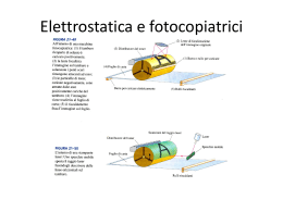
Applicazioni (fotocopiatori-motore elettrico
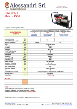
BI6C1T3/1 Matr. n.4560
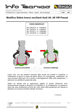
Modifica Sidem bracci oscillanti Audi A4, A6 VW Passat
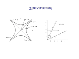
Diapositiva 1 - Dipartimento di Fisica