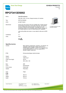
REMOTE ADJUSTER
Documento valido solo come allegato alle istruzioni 98.9469.60
Document valid only as attachment of instructions 98.9469.60
CONTENUTO KIT - KIT CONTENTS
COMPONENTE 1
Remote adjuster “A”, da fissare
direttamente alla pompa freno
RCS mediante il terminale “B”
(fornito con 4 grani vite) e
dotato di forcella “C”.
COMPONENT 1
Remote adjuster “A”, to be
fitted directly to RCS master
cylinder by means of flange “B”
(provided with 4 grub screws)
and equipped with fork“C”.
COMPONENTI 2,3,4
Semicollarini “D” per fissare,
tramite le viti “E”, la forcella
“C” al manubrio moto; molla
“F” da sostituire a quella
originale della pompa freno
RCS.
COMPONENTS 2,3,4
Semicollars “D” to fit, by
means of screws “E”, the fork
“C” to the handle bar; spring
“F” to replace the original
one from RCS master
cylinder.
MONTAGGIO - ASSEMBLY
PASSO 1
Smontare dalla pompa freno RCS il pomello
e la molla, lubrificare il perno pompa e la
parte interna della leva utilizzando
lubrificante “CRC”. ATTENZIONE: il pomello
e la molla originale, una volta smontati,
non sono più utilizzabili!
STEP 1
Remove knob and spring from RCS master
cylinder, grease the master cylinder pin
and the inner side of the lever, by means of
lubricant oil “CRC”. CAUTION: once
removed, the original knob and spring
cannot be used anymore!
PASSO 2
Sfilare il terminale “B” svitando i due grani
vite; tagliare il cavo (secondo una direzione
inclinata di 30° rispetto a quella del cavo
stesso) e la guaina cavo per ottenere la
lunghezza desiderata, lasciando che il cavo
sporga dalla guaina di almeno 12 mm.
STEP 2
Remove flange “B” by unscrewing two grub
screws; cut the metallic wire (following a 30°
inclination of the metallic coils direction) and
the sheath off, in order to get the proper
length. The metallic wire has to stick out of
the sheath at least 12 mm.
98.8364.26 REV.0
PASSO 3
Posizionare la molla “F”, fornita all’interno
del kit, ed il terminale “B”; mantenendo
premuto il terminale “B” contro la pompa
freno RCS, avvitare i 2 grani vite per
garantirne il fissaggio.
STEP 3
Set the spring “F”, provided with the kit,
and the flange “B”; pushing flange “B” on
RCS master cylinder, tighten the two grub
screws to ensure the fastening.
PASSO 4
Inserire il cavo all’interno del terminale
“B”; mantenendo premuto il cavo contro il
terminale “B”, serrare i 2 grani vite per
garantirne il fissaggio.
STEP 4
Put the cable inside the the flange “B”;
pushing the cable on the the flange “B”,
tighten the two grub screws to ensure the
fastening.
PASSO 5
Posizionare uno dei due semicollarini “D”
sul lato sinistro del manubrio, inserendo
nell’apposita sede la forcella “C”.
STEP 5
Set one semicollars “D” on left side of
handle bar, fitting the fork “C” in the
proper place.
PASSO 6
Posizionare il secondo dei due
semicollarini “D”, in modo da accoppiarsi
alla forcella “C”; serrare le due viti “E” così
da garantire il fissaggio del remote
adjuster “A” al manubrio.
STEP 6
Set the second semicollars “D”, in order to
match it to the fork “C”; tighten the two
screw “E” to secure remote adjuster “A” to
handle bar.
98.8364.26 REV.0
Scaricare