ESPANOL
ITALIANO
INSTRUCTIONS
BEDIENUNGSANLEITUNG
MANUEL D'INSTRUCTIONS
MANUAL DE INSTRUCCIONES
ISTRUZIONI
FRENCH
DEUTSCH
ENGLISH
COLOUR VIDEO CAMERA
FARB-VIDEOKAMERA
CAMERA VIDEO COULEUR
CAMERA DE VIDEO A COLOR
TELECAMERA A COLORI
For Customer Use:
Enter below the Serial No. which
is located on the body.
Retain this information for future
reference.
Model No.
Serial No.
This instruction book is made from 100% recycled paper.
Thank you for purchasing the colour video camera.
Before you begin operation this unit. Please read the instructions
carefully to be sure you get the best possible performance.
For USA and CANADA
WARNING:
TO PREVENT FIRE OR SHOCK HAZARD, DO NOT
EXPOSE THIS UNIT TO RAIN OR MOISTURE.
CAUTION
RISK OF ELECTRIC SHOCK
DO NOT OPEN
CAUTION :
TO REDUCE THE RISK OF ELECTRIC SHOCK,
DO NOT REMOVE COVER (OR BACK).
NO USER SERVICEABLE PARTS INSIDE.
REFER SERVICING TO QUALIFIED SERVICE PERSONNEL.
The lightning flash with arrowhead symbol, within an
equilateral triangle is intended to alert the user to the
presence of uninsulated “dangerous voltage” within
the product's enclosure that may be of sufficient magnitude to constitute a risk of electric shock to persons.
The exclamation point within an equilateral triangle
is intended to alert the user to the presence of important operating and maintenance (servicing) instructions in the literature accompanying the appliance.
Information for USA
This device complies with Part 15 of the FCC Rules.
Changes or modifications not approved by the original manufacture could void the user's authority to operate the equipment.
1
AVERTISSEMENT:
POUR EVITER LES RISQUES D'INCENDIE OU
D'ELECTROCUTION, NE PAS EXPOSER
L'APPAREIL A L'HUMIDITE OU A LA PLUIE.
INFORMATION (FOR CANADA)
RENSEIGNEMENT (POUR CANADA)
This Class B digital apparatus complies with Canadian ICES003.
Cet appareil numérique de la classe B est conforme à la
norme NMB-003 du Canada.
Page
Features ..................................................................................... 2
Precautions ................................. .............................................. 3
Controls, connectors and indicators ........................................... 4
Setup functions .......................................................................... 6
Connection ............................................................................... 13
Lens ......................................................................................... 14
Installation of camera ............................................................... 16
How to use the ferrite core ...................................................... 17
Specifications ........................................................................... 18
䡲 High-quality picture provided by the 1/2-inch, 470,000-pixel (440,000
effective pixel)(E type), 410,000-pixel (380,000 effective pixel) (U
type), high-performance design CCD with 470 TV line horizontal
resolution and 0.95 lx (25%, F1.2) minimum object illumination.
䡲 Backlight compensation (BLC) detecting areas can be selected from
4 fixed patterns as well as from two user-selectable patterns.
䡲 Highlight inverter (HLI) function makes the picture around the position of a highlight easier to see.
䡲 Lens mount switching mechanism makes it possible to use either
a C-mount lens or CS-mount lens.
䡲 Menu set-up system eliminates the need of setting operations
using switches and controls.
䡲 Always make a prior test recording to help optimise the final
recording.
2
ENGLISH
Features
Contents
Precautions
• Avoid installing the unit in following locations.
• Places exposed to rain or moisture
• Places with an ambient temperature outside the range of –10
to 50°C (operation) or from 0 to 40°C (recommended).
• Places subject to excessive dust or to oil or gas.
• When this unit is used with AGC ON, an image recorded in a dark
place may look noisy due to the automatic boost in sensitivity.
This is not a malfunction.
• When this unit is used with the AUTO white balance control, the
recorded colours may differ slightly from the actual colours due to
the operation of the automatic-tracking white balance control circuit. This is not a malfunction.
• When a bright object (such as a lamp) is shot, a white, comet-tail
phenomenon may be observed above and below the bright object
on the screen. This is a phenomenon (called smear) inherent in
CCD image pickup devices and is not a malfunction.
• The electronic shutter speed of this unit has been set to 1/50 [1/
60] second at the factory. If you use this unit under fluorescent
lamps in an area with the local power frequency of 60 [50] Hz,
switch the shutter speed to 1/120 [1/100] sec. (The sensitivity will
be degraded slightly at 1/120 [1/100] sec.) E type [U type]
• Lens aperture will be open when the electronic shutter is operated on AUTO mode with an auto iris lens in use, To avoid this, set
the shutter to any mode other than AUTO or use a manual (fixed)
iris lens.
• When the electronic shutter is set to the AUTO mode while this
unit is used under fluorescent lamp illumination, flickering may be
observed in the picture. This is a phenomenon caused by the relationship between the light’s power frequency and shutter speed,
and is not a malfunction.
3
• When using a zoom lens, it is recommended to run the camera
with your zoom lens attached and check the backfocus before
camera installation. The same applies to lens attached and check
the backfocus before camera installation. The same applies to lens
level adjustment. (See the lens instruction manual for details.)
• Be sure to attach the provided ferrite core to the lens cable or
power cable to be connected with this camera to minimize unnecessary radiation.
• Avoid istalling in places where there is radiation.This could damege
CCD and other components and cause a malfunction.
• Avoid installing in places where there are strong electro-magnetic
waves or magnetism. the picture could be distorted.
• Avoid instanning in places where the camera would be subject to
strong vibrations. This could damage components and degrade
the picture.
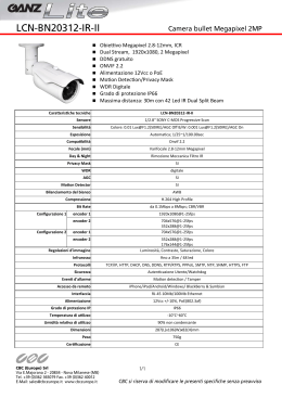
Controls, connectors and indicators
4
5
7
ENGLISH
6
3
2
1
Camera mounting holes (1/4 inch)
This screw hole is used to install the camera on a mount to
PAN/TILT UNIT.
turning it clockwise after turning this ring. This camera has
been adjusted to the optimum position for the C mount before
shipment.
Camera mounting bracket locking screws ( x 2 : M2.6 x 5mm)
Do not use any screw longer than 5 mm.
[BF LOCK] Backfocus locking screw
This screw locks the backfocus adjustment mechanism.
Camera mounting bracket
The camera mounting bracket is mounted on the bottom of
the camera at the factory. It can be installed on the top of the
camera if necessary. Fit the mounting bracket on the top of
the camera head with the two screw
.
Lens mount
The lens mount is compatible with C-mount lenses (1/2 and 2/
3 inch) and CS-mount lenses (1/2 inch).
Backfocus adjustment ring
This ring both allows the adjustment of the backfocus to and
switch as the lens mounting method between C and CS.
Loosen the BF LOCK screw
by turning it counterclockwise
before turning this ring, and be sure to secure screw by
[DC IRIS] DC iris connector
Connect to an auto-iris lens which does not incorporate an EE
amplifier. (See “Lens” on page 14.)
4
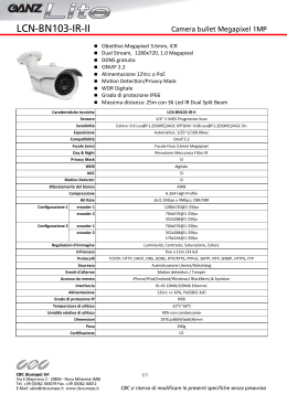
Controls, connectors and indicators (continued)
11
12
Y/C OUT
10
[Y/C OUT] Y/C output connector
This 4-pin connector outputs the luminance and chrominance
signal.
• Pin configuration of Y/C OUT connector
VIDEO IRIS
POWER
13
VIDEO
OUT
CAMERA
SET UP
SET
1
+
9
14
2
–
SYNC
IN
8
SEE INSTRUCTION
MANUAL
3
4
VIDEO GND + 9 V
2
1
AC 24V
DC 12V
CLASS 2 ONLY (For U.S.A use)
ISOLATED POWER ONLY (For EUROPEAN use)
[SYNC IN] Sync signal input connector
This BNC connector accepts the input of an external sync signal such as a composite video (VBS) or black burst (BB) signal.
When a sync signal is input into this connector, the camera
operation is automatically synchronized with the external sync
signal.
The 75-ohm termination of this connector can be switched
on/off on the menu screen as required. (For details, see
“TERM. [75-ohm termination setting]” on page 7.)
5
GND
GND
Luminance (Y, 1 V(p-p), 75-ohm)
E type: Chrominance (C, 0.3 V(p-p), 75-ohm)
U type: Chrominance (C, 0.286 V(p-p), 75-ohm)
[VIDEO IRIS] Video iris connector
Connect to an auto-iris lens incorporating an EE amplifier. (See
“Lens” on page 14.)
[DC12V}/AC24V`] Power input connector
Connect a DC 12 V} ± 10% or AC 24 V` ± 10%, 50/60 Hz
power supply.
+ DC12 V
– Power
2
–
[POWER] Power indicator lamp
This lights when power is supplied to the camera.
1
2
3
4
Signal
[CAMERA SET UP] Camera set-up screen operation buttons
These buttons are used in the set-up operations.
For details, see “Set-up functions” from page 6.
1
+
[VIDEO OUT] Video signal output connector
This BNC connector outputs a composite video signal. Connect this to the video input connector of a video monitor,
switcher, etc.
Pin No.
AC 24V
DC 12V
AC24 V
Power
Setup functions
The camera is adjusted using the CAMERA SETUP screen.
Press the SET button to display the CAMERA SETUP screen on
the monitor.
CAMERA SETUP screen
– – C AME R A S E T U P – –
䢇 SYNC ADJUST menu
For settings related to the sync signals.
1. Move the cursor to “SYNC ADJUST”.
2. Press the SET button to display the
SYNC ADJUST menu.
(See pages 7 and 8 for the operating
procedure.)
– – S Y NC A D J U S T – –
> T E RM .
H PHASE
S C COA R S E
SC F I NE
L I NE L 0 CK
V COA R S E
V F I NE
E ND
ON
25
1
128
OF F
1
128
> S Y NC A D J U S T
V I D EO A D J U S T
MOD E S E L E C T
E ND
MEMOR Y
䢇 VIDEO ADJUST menu
For settings related to the video signal.
1. Move the cursor to “VIDEO ADJUST”.
2. Press the SET button to display the
VIDEO ADJUST menu.
(See pages 8 and 9 for the operating
procedure.)
– – V I D EO A D J U S T – –
Operation buttons
CAMERA
SET UP
SET
Press to display the SET UP screen
(current adjustment condition).
To clear the function, move the cursor
> to "END" and press here. The SET UP
screen returns to the normal screen.
Press to move the cursor > or select an
adjustment option.
>IRIS
CO L OUR
PEDES T A L
E NH A NC E
HU E
E ND
0
0
0
0
0
䢇 MODE SELECT menu
For settings related to the camera functions.
– – MOD E S E L E C T – –
Press to select the mode of the adjusted item or set its level.
>ID
OF F
AGC GA I N
18dB
S U P E R AGC
OF F
S HU T T E R
MA NU (
BLC
OF F
Av : Pk
8: 2
W . BA L
AUTO
HL I
OF F
E ND
)
1. Move the cursor to “MODE SELECT”.
2. Press the SET button to display the
MODE SELECT menu.
(See pages 9 to 12 for the operating procedure.)
6
ENGLISH
䡵 CAMERA SETUP screen
Setup functions (continued)
SYNC ADJUST menu
䡵 TERM. [75-ohm termination setting]
– – S Y NC A D J U S T – –
> T E RM .
H PHASE
S C COA R S E
SC F I NE
L I NE L 0 CK
V COA R S E
V F I NE
E ND
ON
25
1
128
OF F
1
128
Set according to whether the signal input
into the sync signal input terminal
is
to be terminated with 75 ohms or not.
ON : Terminated with 75 ohms
OFF : Open
Initial set ON.
Note:
The terminal is open when the power is OFF.
䡵 H PHASE [Horizontal phase adjustment]
– – S Y NC A D J U S T – –
T E RM .
> H PHASE
S C COA R S E
SC F I NE
L I NE L 0 CK
V COA R S E
V F I NE
E ND
ON
25
1
128
OF F
1
128
Adjustment of the H phase in gen-lock operation. Adjust with reference to another
camera (or system).
Variable range
: 0 to 50.
Initial set
: 25.
䡵 SC COARSE [Sub-carrier phase coarse adjustment]
– – S Y NC A D J U S T – –
T E RM .
H PHASE
> S C COA R S E
SC F I NE
L I NE L 0 CK
V COA R S E
V F I NE
E ND
ON
25
1
128
OF F
1
128
Coarse adjustment of the SC phase in genlock operation. The SC phase can be varied
by up to 90° in each direction.
Adjust with reference to another camera (or
system) and together with the SC FINE adjustment.
Variable range
: 1, 2, 3, 4.
Initial set
: 1.
Note :
Only the
button is effective. The
button does not operate.
Noise may be generated when END CLEAR is performed after sc coarse
adjustment. In this case, perform the sc coarse adjustment again.
7
䡵 SC FINE [Sub-carrier phase fine adjustment]
– – S Y NC A D J U S T – –
T E RM .
H PHASE
S C COA R S E
> SC F I NE
L I NE L 0 CK
V COA R S E
V F I NE
E ND
ON
25
1
128
OF F
1
128
Fine adjustment of the SC phase in genlock operation.
Variation range : 0 to 255.
Initial set
: 128.
Note:
Adjust SC COARSE and SC FINE only after adjusting H PHASE.
䡵 LINE LOCK [Line lock setting]
– – S Y NC A D J U S T – –
T E RM .
H PHASE
S C COA R S E
SC F I NE
> L I NE L 0 CK
V COA R S E
V F I NE
E ND
ON
25
1
128
OF F
1
128
Setting when the vertical sync signal of the
camera is to be locked with the AC power
frequency.
ON : LL mode is activated.
OFF : LL mode is unactivated.
Set to OFF when using INT (internal sync)
or EXT (external sync).
Initial set : OFF.
Notes:
• Do not apply an external sync signal in the LL mode.
• The display will be switched over between ON and OFF, however, the LL function is only available with the power frequency
of 50 [60] Hz. ( E type [U type] )
– – S Y NC A D J U S T – –
T E RM .
H PHASE
S C COA R S E
SC F I NE
L I NE L 0 CK
> V COA R S E
V F I NE
E ND
ON
25
1
128
OF F
1
128
Adjustment to align the vertical phase with
another camera operating in the line lock
(LL) mode. The phase can be varied by up
to 180° in courses 1 and 2. Adjust together
with the V FINE adjustment.
Variable range
: 1, 2.
Initial set
: 1.
䡵 COLOUR [Colour level]
– – V I D EO A D J U S T – –
IRIS
> CO L OUR
PEDES T A L
E NH A NC E
HU E
E ND
0
0
0
0
0
䡵 V FINE [Vertical phase fine adjustment]
– – S Y NC A D J U S T – –
T E RM .
H PHASE
S C COA R S E
SC F I NE
L I NE L 0 CK
V COA R S E
> V F I NE
E ND
ON
25
1
128
OF F
1
128
Fine adjustment of the vertical phase in the
LL mode.
Variable range
: 0 to 255.
Initial set
: 128.
䡵 PEDESTAL [Pedestal level]
– – V I D EO A D J U S T – –
IRIS
CO L OUR
> PEDES T A L
E NH A NC E
HU E
E ND
0
0
0
0
0
VIDEO ADJUST menu
䡵 IRIS [Iris level]
– – V I D EO A D J U S T – –
>IRIS
CO L OUR
PEDES T A L
E NH A NC E
HU E
E ND
0
0
0
0
0
Adjustment of the luminance level of the
video signal.
Variable range
: – 5 to 5.
Initial set
: 0.
• To raise the level .. Increase number (
)
• To raise the level .. Decrease number (
)
Note:
When using a video-iris lens or DC-iris lens or when SHUTTER
is set to AUTO, set the AGC GAIN of MODE SELECT menu to 0
before starting iris level adjustment.
Adjustment of the colour level of the video
signal.
Variable range
: – 5 to 5.
Initial set
: 0.
• To increase colour saturation
).
.......... Increase the number (
• To decrease colour saturation
......... Decrease the number (
).
Adjustment of the pedestal level of the
video signal.
Variable range
: – 5 to 5.
Initial set
: 0.
• To brighten picture
......... Increase the number (
).
• To darken picture
.......... Decrease the number (
).
䡵 ENHANCE [Enhancement level]
– – V I D EO A D J U S T – –
IRIS
CO L OUR
PEDES T A L
> E NH A NC E
HU E
E ND
0
0
0
0
0
Adjustment of the aperture control level of
the video signal.
Variable range
: – 5 to 5.
Initial set
: 0.
• To sharpen the picture (by enhancing the
aperture control and contour level)
......... Increase the number (
).
• To soften the picture (by attenuating the
aperture control and contour level)
......... Decrease the number (
).
8
ENGLISH
䡵 V COARSE [Vertical phase coarse adjustment]
Setup functions (continued)
䡵 HUE [Hue adjust]
Adjustment of the hue of the video signal.
Variable range: – 5 to 5. Initial set: 0.
•To make yellowish
......... Increase the number (
).
•To make reddish
......... Decrease the number (
).
– – V I D EO A D J U S T – –
IRIS
CO L OUR
PEDES T A L
E NH A NC E
> HU E
E ND
0
0
0
0
0
MODE SELECT menu
䡵 ID [Camera ID name/number]
– – MOD E S E L E C T – –
>ID
OF F
AGC GA I N
18dB
S U P E R AGC
OF F
S HU T T E R
MA NU (
BLC
OF F
Av : Pk
8: 2
W . BA L
AUTO
HL I
OF F
E ND
)
The camera ID can be up to 24 characters.
ON : The camera ID is displayed.
OFF : The camera ID is not displayed.
EDIT : The camera ID can be set.
Setting method
or
button and press the SET but1. Select “EDIT” with the
ton. The CAMERA ID screen appears, with the character cursor and the first character in the input section blinking.
Note:
The cursor “>” of MODE SELECT menu cannot be moved when
ID is set at EDIT.
2. Select a character with the
or
button.
(Enter a space in positions where no character is to be input.)
3. Press the
button to set the character. Then the input sec-tion for
the next character starts to blink.
(Press the
button to return to the previous character.)
4. After all characters have been input by repeating steps 2 and 3, press
the SET button. The CAMERA SETUP screen is displayed again.
5. ID appears when set to ON.
䡵 AGC GAIN [Automatic Gain Control]
– – MOD E S E L E C T – –
Monitor screen when “ON”
is selected (initial setup)
Monitor screen when “EDIT” is
selected
Blinking character cursor
C AME R A I D
0123456789– : / ,
A B CD E F GH I J K L MNO
PQR S T U VWX Y Z
a b c d e f g h i j k l mn o
pq r s t u vwx y
(All ‘Space’ in initial set)
Camera ID
(max. 24 characters)
9
Camera ID input section
Space
ID
OF F
> AGC GA I N
18dB
S U P E R AGC
OF F
S HU T T E R
MA NU (
BLC
OF F
Av : Pk
8: 2
W . BA L
AUTO
HL I
OF F
E ND
)
Setting the max. gain of the AGC (Automatic
Gain Control).
Variable range: 0, 9 and 18 dB.
Initial set: 18 dB.
䡵 SUPER AGC [High-sensitivity automatic gain control]
– – MOD E S E L E C T – –
ID
OF F
AGC GA I N
18dB
> S U P E R AGC
OF F
S HU T T E R
MA NU (
BLC
OF F
Av : Pk
8: 2
W . BA L
AUTO
HL I
OF F
E ND
)
Use this function if the picture is not bright
enough when AGC GAIN is set to 18 dB.
ON : The gain is further increased.
OFF : The gain is not increased.
Initial set
: OFF.
In such a case, the flickering and white balance variation can be
improved by setting the shutter speed to 1/100 [1/120] in an area
where the local power supply frequency is 50 [60] Hz or to 1/60 [1/
50] in an area where it is 60 [50] Hz. E type [U type]
Note:
When shutter speed is higher, goes to worse the smear which
is a phenomenon inherent to CCDs.
䡵 BLC [Back light compensation]
– – MOD E S E L E C T – –
䡵 SHUTTER [Electronic shutter]
Set according to whether the electronic
shutter is to be switched manually or automatically.
)
• MANUAL
: 1/50 [1/60] s, 1/120 [1/100]s,
1/250s, 1/500s, 1/1000s,
1/2000s, 1/4000s, 1/10000s.
• AUTO
: 1/50 [1/60] - 1/100000s
Variable range
( E type [U type] )
Initial set
: MANU ( 1/50 [1/60] )
– – MOD E S E L E C T – –
ID
OF F
AGC GA I N
18dB
S U P E R AGC
OF F
> S HU T T E R
MA NU (
BLC
OF F
Av : Pk
8: 2
W . BA L
AUTO
HL I
OF F
E ND
<Setting in MANUAL mode>
1. Press SET button in MANU ( 1/50 [1/60] ) mode, and ( ) are
removed to allow setting.
2. Change the shutter speed with
or
button.
3. Press SET button again, and ( ) comes out to finish shutter
speed setting.
If the AUTO mode or a high-speed shutter mode is selected under
fluorescent lighting, the picture could flickering or the white balance could be un-stable.
ID
OF F
AGC GA I N
18dB
S U P E R AGC
OF F
S HU T T E R
MA NU (
>BLC
OF F
Av : Pk
8: 2
W . BA L
AUTO
HL I
OF F
E ND
)
Set when there is a strong light source in
the background. The BLC provides four
fixed areas and 2 user-set areas.
Variation values : OFF, AREA1, AREA2, AREA3, AREA4, EDIT1, EDIT2.
Factory setup
: OFF.
1. Select AREA with
buttons.
2. Press the SET button to show ”detecting“. Set the area as required.
3. When setting is done, press the SET button again and MODE
SELECT screen will resume.
Fixed area
AREA 1
AREA 2
AREA 3
Detecting area
Detecting
area
Detecting
area
AREA 4
Detecting
area
10
ENGLISH
Notes:
• When AGC GAIN is set to 9 or 18 dB or when SUPER AGC is
set to ON, dark parts of the picture may look noisy. This is because sensitivity increased and it is not a malfunction.
• With SUPER AGC set to ON, the level reaches 18 dB even with
AGC GAIN at 0 or 9 dB. AGC GAIN display does not change
however.
• The camera ID level can be adjusted by turning SUPER AGC on
and off.
• The response of the SUPER AGC may be retarded against the
acute level changes.
Setup functions (continued)
EDIT 1
Detecting
area
Press the SET button
EDIT 1
Detecting
area
EDIT 2
Detecting area
Press the SET button
EDIT 2
Detecting area
11
User set area
EDIT1
Use this area when the metered area is
located at the center of the field of view.
•
button .... Move the detecting
area to the left.
•
button .... Move the detecting
area upwards.
•
button .... Move the detecting
area to the right.
•
button .... Move the detecting
area downwards.
EDIT2
Use this area when the metered area
is located at the edge of the screen.
•
button ... Move the undetecting
area to the left.
•
button ... Move the undetecting
area upwards.
•
button ... Move the undetecting
area to the right.
•
button ...Move the undetecting
area downwards.
Note:
The detecting areas displayed with
AREA1 to 4 and EDIT1 and 2 are
for reference and may be different
from the actual detecting areas.
䡵 Av:Pk [Average value: Peak value]
– – MOD E S E L E C T – –
ID
OF F
AGC GA I N
18dB
S U P E R AGC
OF F
S HU T T E R
MA NU (
BLC
OF F
>Av : Pk
8: 2
W . BA L
AUTO
HL I
OF F
E ND
)
Sets the ratio between the average value
(Av) and peak value (Pk) in exposure detection.
Use this setting when a video-iris lens or
DC-iris lens is used or when SHUTTER is
set to AUTO.
Variation range : 5:5, 6:4, 7:3, 8:2, 9:1, 10:0.
Initial set
: 8:2.
Av value effect : Increase the Av value when part other than the
high light part are dark and look washed out. This
setting is used when there is artificial lighting in a
dark room.
(Example: 10:0)
Pk value effect : Increase the Pk value when halation tends to be
observed in the highlight part of the picture. (Example: 5:5)
䡵 W.BAL [White balance]
Automatic or manual setting of the white
balance in the color temperature range of
2500K to 7000K.
– – MOD E S E L E C T – –
ID
OF F
AGC GA I N
18dB
S U P E R AGC
OF F
S HU T T E R
MA NU (
BLC
OF F
Av : Pk
8: 2
>W . B A L
AUTO
HL I
OF F
E ND
)
AUTO
: Automatic color tem- perature
tracking mode.
MANUAL : Manual adjustment mode.
Initial set : AUTO.
>R : – – – – – – – – – – + – – – – – – – : B
Mg : – – – – – – – – – – – – – + – – – – : G
E ND
1. Adjustment screen appears when pressing the SET button on the “MANUAL”
mode.
2. Adjust with
or
button.
button is used for adjustment to red
(magenta, whereupon + is moved to R
(Mg).
button is used for adjustment to blue
(green), whereupon + is moved to B (G).
3. Switching between R/B and Mg/G can be
or
button.
performed with
<How to set HLI>
or
button, and OFF is changed to ON (1)to enter
1. Press
the HLI mode.
2. Press SET button to remove ( ), and ON1is displayed to allow
on-screen selection.
3. Monitoring the screen, select one of ON1,ON2 and ON3 with
or
button.
4. Press SET button again, and ( ) comes out to finish setting.
䡵 To clear the setup functions
– – C AME R A S E T U P – –
GE N L OC K
V I D EO A D J U S T
MOD E S E L E C T
> E ND
MEMOR Y
Note:
In AUTO mode, the optimum white balance may not be obtained when the light source has a color temperature outside
the adjustment range.
In such a case, set W.BAL to the MANUAL mode.
䡵 HLI [Highlight inverter]
– – MOD E S E L E C T – –
ID
OF F
AGC GA I N
18dB
S U P E R AGC
OF F
S HU T T E R
MA NU (
BLC
OF F
Av : Pk
8: 2
W . BA L
AUTO
>HL I
OF F
E ND
)
The HLI function inverts the highlight part
of picture so that the parts around it can
be seen more clearly.
Variable values : OFF, ON(1), ON(2), ON(3)
Initial set
: OFF
ON is adjustable in three degrees. The smaller
the number, the brighter the area to be reversed.
1. Move the cursor “>” to END.
or
button.
2. Select END mode with
MEMORY : Set value holds.
CLEAR
: All the set values resume the
values.
Note:
ID (camera title) is not cleared with CLEAR.
3. Press SET button to set the END mode, resuming the initial
setting screen.
12
ENGLISH
MANUAL adjustment screen
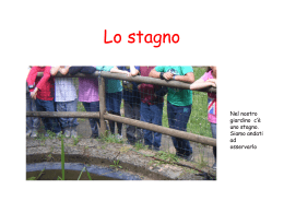
Connection
䡵 System connection example
● Do not turn on the power of any component before all connections have been completed.
● Read the instruction manuals of the components to be connected
carefully.
Auto-iris lens with built-in EE
amp (or auto-iris lens without
EE amp)
Genlock connection
With some systems, genlocking by applying an external sync
input requires the horizontal phase (H PHASE) and/or color phase
(SC COARSE) (in case the external sync signal is a composite
video or black burst signal) to be adjusted.
Note:
• Genlocking is not possible with a signal containing too much
jitter, such as a VCR or videodisc playback signal.
To video input
connector
To VIDEO IRIS
(or to DC IRIS on side panel)
Y/C OUT
VIDEO IRIS
POWER
VIDEO
OUT
CAMERA
SET UP
VIDEO GND + 9 V
+ (DC12V})
1
+
SET
– (DC12V})
2
–
SYNC
IN
SEE INSTRUCTION
MANUAL
AC 24V
DC 12V
CLASS 2 ONLY (For U.S.A use)
ISOLATED POWER ONLY (For EUROPEAN use)
From composite video
or black burst output
connector
Sync signal
generator
13
To DC12V or
AC24 V input
connector
Power supply
(DC 12 V})/(AC 24 V`)
Caution
• Be sure to observe the correct +, – polarity when connecting
a DC 12 V} power input.
• The DC 12 V} power should have a ripple voltage of no more
than 50 mV.
• Never connect the DC 12 V} and AC 24 V` power inputs
simultaneously.
• Be sure to attach the provided ferrite core to the lens cable or
power cable to be connected with this camera. (see page 17
for details)
Lens
䡵 Lens mounting procedure
Fig. 1
Fig. 1-1
era. The camera has been set for a C mount before shipment
(Figure 1-1). When mounting a CS-mount lens, loosen the BF
LOCK screw ( on page 4) by turning it counter-clockwise and
turn the backfocus adjustment ring ( on page 4) in the direction of the arrow in Figure 1-1 to switch the mounting method.
(Figure 1-2 shows the camera set for a CS mount lens.)
Fig. 1-2
Fig. 1-3
ENGLISH
1. Check the mounting of your lens before attaching it to the cam-
C mount
CS mount
2. Mount the lens on the camera by turning the lens clockwise
and adjust its position.
Flange back
Lens
Flange back
Distance L
C-mount lens
17.526 mm
No more than 10 mm
CS-mount lens
12.5 mm
No more than 5.5 mm
If the lens does not incorporate an EE amp, connect the
cable to the DC IRIS connector on the side panel (Figure 2-1).
If the lens incorporates an EE amp, connect the cable to
the VIDEO IRIS connector on the rear panel (Max 50mA).
Fig. 2
B
A
2
Fig. 2-1
L N
Lens
Optimum
imaging
point
the camera.
ALC LEVEL
L
3. When an auto-iris lens is used, also connect the lens cable to
Av Pk
Caution
• The ring cannot be turned by more than a certain amount with
your finger. Use a thin object (screwdriver tip, etc.) to turn the
ring (Figure 1-3).
• Distance L of the lens mounting section shown in the following illustration should comply with the condition shown in the
following table. Never use a lens with a flange back distance
L greater than, the one Specified in the chart below. As this
will damage the inside of the camera or may make normal
mounting impossible. Also, be careful not to attempt to mount
a C-mount lens while the camera is set for a CS mount.
Connector pin layout (DC IRIS) (External view of camera connector)
1
2
3
4
1: Brake –
2: Brake +
3: Drive +
4: Drive –
14
Lens (continued)
• After completing connections as shown in “Connection” on page
13, supply power to the camera, display a picture on the monitor
and check the image.
Auto-iris lenses have generally been adjusted for the widest applicability before shipment, but readjustment may sometimes
be necessary depending on the conditions of the objects to be
shot and the lens combination. If the picture recorded using such
a lens looks unnatural, readjust as shown below.
䡵 Backfocus adjustment
The backfocus has been adjusted before shipment so that the widest range
can be obtained with C-mount lenses, but readjustment is necessary when
the lens mount is switched to the CS mount or a combination lens is used.
When necessary, readjust the backfocus by the following procedure.
<When a fixed – focus lens is used>
Readjust the backfocus when the optimum focusing cannot be obtained
by adjusting the focusing ring of the lens.
1. Loosen the BF LOCK screw by turning
• Auto-iris lens with built-in EE amp
it counterclockwise with a screwdriver.
2. Optimize the focus by turning the
L N
Av Pk
ALC LEVEL
LEVELadjustment
Monitor screen
To darken picture
To brighten picture
Backfocus adjustment
ring
LEVEL turning direction
Counterclockwise (toward L)
Clockwise (toward H)
BF LOOK
backfocus adjustment ring.
3. Lock the BF LOCK screw by turning it
clockwise.
BF LOCK
(backfocus look) ring
<When a zoom lens is used>
ALC adjustment
This cannot be adjusted on the lens. The ALC should
be adjusted as described in “Av : Pk [Average value :
Peak Value]” on Page 11.
Caution
Do not turn the LEVEL control too far towards “L” as this could
cause the AGC of the camera to increase the gain, making the
picture look rough.
• Auto-iris lens without EE amp
Re-adjust as descried in “IRIS [Iris level]” on page 8.
15
Readjust the backfocus when focusing is lost during zooming (from wide angle
to telephoto).
1. Loosen the BF LOCK screw by turning it counterclockwise with a
screwdriver.
2. Shoot a fine pattern of as dark as possible an object at a distance of
more than 3 meters.
3. Set the zoom for telephoto and adjust the focus with the lens’s focusing ring.
4. Set the zoom for wide angle and adjust the focus by turning the backfocus
adjustment ring. (Refer to “When a fixed-focus lens is used” above.)
• Repeat steps 3 and 4 a few times.
5. Lock the BF LOCK screw by turning it clockwise.
Installation of camera
● Mounting from the top
Remove the CAMERA MOUNTING BRACKET from the bottom
of the camera by removing three fixing screws as shown 2. Attach the CAMERA MOUNTING BRACKET to the top, then mount
the camera on the Fixing Unit as shown 3. Make sure that three
original screws are used when mounting the CAMERA MOUNT
BRACKET; longer type screws (over 5mm) may damage inner
components.
(This camera is used indoor and under similar conditions.)
Hole to lock against swiveling
ENGLISH
● Mounting from the bottom
This camera is originally designed to be mounted from the bottom, as shown 1. The hole is standard photographic pan-head
screw size (1/4” -20). Example the Fixing unit or Pan/Tilt unit.
Camera mounting screw hole
• Special precautions must be taken for ganging the camera
on a wall or a ceiling.
• We are by no means liable for any dropping or other accident due to improper installation.
Shown 2
Shown 1
Shown 3
L N
L N
ALC LEVEL
Av Pk
BF LOOK
ALC LEVEL
Av Pk
16
How to use the ferrite core
To retain electromagnetic compatibility, use the provided ferrite cores when
connecting to the lens or the power source.
Y/C OUT
VIDEO IRIS
POWER
VIDEO
OUT
CAMERA
SET UP
2
–
SYNC
IN
Video-iris lens
(or galvanometnc-iris lens)
VIDEO GND + 9 V
1
+
SET
SEE INSTRUCTION
MANUAL
AC 24V
DC 12V
CLASS 2 ONLY (For U.S.A use)
ISOLATED POWER ONLY (For EUROPEAN use)
Wire clamp
Power supply
(DC 12V or AC 24V)
Ferrite core
To power input terminal
Wire clamp
Ferrite core
To VIDEO IRIS connector
(or DC IRIS connector)
Notes:
Install the ferrite cores within 50 mm of the camera-side connectors. (Fasten with the ferrite core with the wire clamp.)
For lens connection
: Pass the lens cable through the ferrite core twice and connect it to the
camera.
For power supply connection : Pass the power cable through the
ferrite core three times and connect
it to the camera.
17
Specifications
Scanning frequency
Horizontal resolution
Video S/N
Minimum illumination
Lens mount
Power supply
Power consumption
Ambient temperatures
Weight
Accessories
ENGLISH
1.5
Dimensions (Unit: mm)
55
Sync systems
: 1/2-inch, interline-transfer CCD
: E type : 440,000 pixels [752(H) x 582(V)]
U type : 380,000 pixels [768 (H) x 494 (V)]
: Internal, external
power sync (E type : 50 Hz areas only
U type : 60 Hz area only)
: E type : 15.625 kHz (H), 50.0 Hz (V)
U type : 15.734 kHz (H), 59.94 Hz (V)
: 470 TV lines (H)
: 48 dB
: 0.95 lx (25%, F1.2, AGC “18 dB”)
: C/CS mount
: AC 24 V ` 50/60 Hz or DC 12 V}
: AC 24 V ` 50/60 Hz 380 mA,
DC 12V} 470 mA
: – 10 to 50°C (operation)
0 to 40°C (recommended)
: 640 g
: • 4-pin iris plug × 1
• 4-pin Y/C plug × 1
• Ferrite core
×2
H=67
Image pickup device
Effective pixels
BF LOOK
W=70
148
D=159
Design and specifications are subject to change without notice.
18
Vielen Dank für den Kauf der Farbvideokamera.
Bevor Sie dieses Gerät in Betrieb nehmen, sollten Sie die Anleitungen
sorgfältig durchlesen,um die bestmögliche Leistung zu erhalten.
WARNUNG:
ZUR VERHINDERUNG VON
FEUER
UND
ELEKTRISCHEN SCHLÄGEN DIESES GERAT NICHT
REGEN ODER FEUCHTIGKEIT AUSSETZEN.
Änderungen der in dieser Bedienungsanleitung enthaltenen
Daten sind vorbehalten.
INHALT
Seite
BESONDERHEITEN .................................................................. 19
VORSICHTSMASSNAHMEN .................................................... 20
REGLER, ANSCHLÜSSE UND ANZEIGEN ............................... 21
EINSTELLFUNKTIONEN ........................................................... 23
ANSCHLÜSSE ........................................................................... 31
OBJEKTIVE ............................................................................... 32
ANBRINGUNG DER KAMERA .................................................. 34
ANWENDUNG DES FERRITKERNS .......................................... 35
SPEZIFIKATIONEN .................................................................... 36
Für eine optimale Endaufnahme sollte immer vorher eine Probeaufnahme gemacht werden.
19
BESONDERHEITEN
● Aufnahmen von hoher Qualität durch 0,5-Zoll-CCD-Hochleistungskonstruktion mit 470.000 Bildpunkten (440.000 effektive Bildpunkte) (E type), 410.000 Bildpunkten (380.000 effektive Bildpunkte) (U type), sowie einer horizontalen Bildzeilenauflösung von
470 Zeilen und einer Mindestobjektbeleuchtung von 0,95 lx (25%,
F1, 2).
● Gegenlichtmeßbreiche können an Hand von 4 Festmustern sowie
2 vom Benutzer einstellbaren Anwendermustern eingestellt
werden.
● Hervorhebungsumkehrfunktion (HLI) macht die Aufnahme bei einer
hervorgehobenen Stelle leichter sichtbar.
● Objektivfassung-Umschaltmechanismus ermöglicht die
Verwendung von Objektiven mit C- oder CS-Fassung.
● Menü-Einstellsystem für leichtere Einstellung,ohne daß Schalter
und Regler verwendet werden müssen.
● Die Kamera sollte nicht an folgenden Orten aufgebaut werden.
• Orte,die Regen oder Feuchtigkeit ausgesetzt sind.
• Orte,an denen die Umgebungstemperatur -10 bis 50 C (Betrieb)
oder 0 bis 40 C (empfohlen) unter- oder überschreitet.
• Orte,die übermäßig Staub,Öl oder Gasen ausgesetzt sind.
● Wenn mit dieser Kamera bei eingeschalteter AGC eine Aufnahme
an einem dunklen Ort gemacht wird,dann könnte sie aufgrund der
automatischen Verstärkung der Lichtempfindlichkeit verrauscht
aussehen. Dies ist jedoch keine Störung.
● Wenn diese Kamera mit der automatischen Weißabgleichregelung
verwendet wird,dann könnten die aufgenommenem Farben
aufgrund des automatischen Nachlaufs der WeißabgleichSteuerschaltung geringfügig von den tatsächlichen Farben
abweichen.Dies ist jedoch kei ne Störung.
● Wenn ein helles Objekt (z.B. eine Lampe) aufgenommen wird,dann
könnte über und unter dem hellen Objekt auf dem Bildschirm ein
Effekt auftreten,der einem Kometenschweif ähnlich ist.Dieser
Effekt ( auch Verwischung oder Unschärfe genannt) ist CCD
Bildaufnahmegeräten eigen und keine Störung.
● Die elektronische Verschlußzeit dieser Kamera wurde werkseitig
auf 1/50 [1/60] Sekunde eingestellt. Wird diese Kamera bei
Leuchtstoff-lampenlicht und einer örtlichen Netzfrequenz von 60
[50] Hz verwendet die Verschlußzeit auf 1/120 [1/100] Sekunde
ändern. (Bei 1/120 [1/100] Sekunden nimmt die Lichtempfindlichkeit
geringfügig ab.) E type [U type]
● Die Objektivöffnung ist offen,wenn der elektronische Verschluß
automatisch betrieben wird und mit einem automatischen IrisObjektiv verwendet wird.Um dies zu verhindern,den Verschluß
mittels einer anderen Betriebsart als AUTO einstellen oder ein
manuelles (festes) Iris-Objektiv verwenden.
● Wenn der elektronische Verschluß auf automatischen Betrieb
(AUTO) eingestellt ist,während die Kamera bei Leuchtstofflampenlicht verwendet wird,könnte im Bild ein Flimmereffekt auftreten.
Dieser Effekt wird durch das Verhältnis zwischen der Lichtnetzfrequenz und der Verschlußzeit verursacht und ist keine Störung.
● Bei Benutzung eines Zoom-Objektivs,die Kamera mit
angebrachtem Zoom-Objektiv laufen lassen und den hinteren
Brennpunkt vor Kamerainstallierung prüfen.Dies gilt ebenfalls für
den Objektivpegel. einstellung (Siehe Objektiv-Bedienungsanleitung
zu Einzelheiten.)
● Das Bild kann Störwellen enthalten oder die Farbe kann ver fülscht
werden, wenn es starken elektromagnetischen Wellen oder
Magnetismus ausgesetzt ist, wie zu Beispiel in der Nähe eins Radio oder F ernseners, Transformator, Motor, usw.
● Die Kamera nicht im Wirkungsbereich von Röntgenstrahlung
anbringen. Hierdurch können der CCD-Chip und andere
Kamera-Komponenten beschädigt werden bzw.
Fehlfunktionen hervorgerufen werden.
● Nicht an Plätzen installieren, wo strake elektromagnetische
Wellen oder Magnetismus auftreten, Dies könnte verzerrte
Bilder verursachen.
● Die Kamera nicht an Vibrationen ausgesetzten Orten
anbringen. Hierdurch können Kamera Kamerakomponenten
beschädigt und die Bildqualität beeinträchtigt werden.
20
DEUTSCH
VORSICHTSMASSNAHMEN
REGLER, ANSCHLÜSSE UND ANZEIGEN
4
6
5
7
3
2
1
Kamerabefestigungslöcher
Dieses Schraubenloch wird für die Befestigung der Kamera
auf einer Halterung oder SCHWENK/KIPPEINHEIT verwendet.
Befestigungsplattenspannschrauben für Kamera (x 2 : M2,6 x 5 mm)
Keine Schraube verwenden, die länger als 5mm ist.
Kamerabefestigungsplatte
Die Kamerabefestigungsplatte wird im Werk an der Unterseite
der Kamera montiert. Wenn erforderlich, kann sie an der
Oberseite der Kamera montiert werden.Die Befestigungsplatte
an der Oberseite des Kamerakopfs mit den zwei Schrauben
anbringen.
Einstellring für hintere Brennweite
Dieser Ring ermöglicht die Einstellung der hinteren Brennweite
sowie das Umschalten zwischen der C und CS Objektivfassung.
durch
Vor dem Drehen dieses Rings die BF LOCK Schraube
21
Dre hen im Gegenuhrzeigersinn lösen und die Schraube
durch Dre hen im Uhrzeigersinn wieder sichern,nachdem der
Ring gedreht wurde. Die kamera wurde vor Versand auf die
optimale Position für die C Fassung eingestellt.
Spannschraube für hintere Brennweite [BF LOCK]
Diese Schraube verriegelt den Einstellmechanismus für die hintere Brennweite.
Objektivfassung
Die Objektivfassung ist mit Objektiven mit C- (1/2 und 2/3 Zoll)
und CS-Fassung Objektiven (1/2 Zoll) kompatibel.
DC Irisstecker [DC IRIS]
An ein automatisches Irisobjektiv anschließen,das keinen EE
Verstärker besitzt. (Siehe “Objektiv” auf Seite 32.)
12
Videosignal-Ausgangsanschluß [VIDEO OUT]
Über diesen BNC Anschluß wird ein zusammengesetztes
Videosignal ausgegeben.An den Videoeingangsanschluß des
Videomonitors,Umschalters,usw. anschließen.
Y/C OUT
10
VIDEO IRIS
POWER
Netzanzeige [POWER]
Leuchtet bei Netzstromzufuhr zur Kamera auf.
13
VIDEO
OUT
CAMERA
SET UP
SET
VIDEO GND + 9 V
Y/C-Ausgangsanschluß [Y/C OUT]
Über diesen 4-poligen Anschluß wird das Helligkeits- und Chrominanzsignal ausgegeben.
1
+
9
14
2
–
SYNC
IN
8
SEE INSTRUCTION
MANUAL
• Stiftanordnung des Y/C Anschlusses
AC 24V
DC 12V
CLASS 2 ONLY (For U.S.A use)
ISOLATED POWER ONLY (For EUROPEAN use)
4
Synchronsignal-Eingangsanschluß [SYNC IN]
Über diesen BNC Anschluß wird der Eingang eines externen
Synchronsignals aufgenommen, wie z.B. ein zusammengesetztes Videosignal (VBS) oder ein Schwarzimpulssignal
(BBS).Wenn über diesen Anschluß ein Synchronsignal
eingegeben wird,dann wird der Kamerabetrieb mit dem externen
Synchronsignal automatisch sychronisiert.
Der 75-Ohm-Abschluß dieses Anschlusses kann wie erforderlich
bei der Menü-Anzeige ein oder ausgeschaltet werden. (zu
Einzelheiten siehe “TERM. (75-Ohm-Abschlußeinstellung)” auf
Seite 24.)
2
3
1
Stift-Nr.
1
2
3
4
Signal
Erdung
Erdung
Helligkeit (Y,1 Vs-s,75 Ohm)
E type : Chrominanz (C,0,3 Vs-s,75 Ohm)
U type : Chrominanz (C, 0,286 Vs-s, 75 Ohm)
22
DEUTSCH
11
REGLER, ANSCHLÜSSE UND ANZEIGEN
Bedienknöpfe für Kameraeinstellbildschirm [CAMERA SET UP]
Mit diesen Knöpfen erfolgt die Betriebseinstellung.
zu Einzelheiten siehe “Einstellfunktionen” auf Seite 23.
Video-Irisanschluß [VIDEO IRIS]
Ein automatisches Irisobjektiv mit einem EE Verstärker
anschlies sen. (Siehe “Objektiv” auf Seite 32.)
Netzeinganganschluß [DC12V}/AC24V`]
Eine GS 12 V} 10% oder WS 24 V` 10%, 50/60 Hz Stromversorgung anschließen.
EINSTELLFUNKTIONEN
KAMERAEINSTELLBILDSCHIRM
Die Kamera wird mittels des Einstellbildschirms (CAMERA
SETUP) eingestellt.
Für Einstellung der CAMERA SETUP Anzeige auf dem Monitor
den SET Knopf drücken.
CAMERA SETUP Anzeige
– – C AME R A S E T U P – –
> S Y NC A D J U S T
V I D EO A D J U S T
MOD E S E L E C T
E ND
MEMOR Y
1
+
+ GS 12 V}
2
–
– Netz
AC 24V
DC 12V
ws 24 V`
Netz
Bedienknöpfe
CAMERA
SET UP
SET
Für Einstellung der SET UP Anzeige drücken.
(derzeitige Einstellung)
Für Aufhebung der Funktion den Cursor > nach
“END” bewegen und hier drücken.Dann wird von
der SET UP Anzeige wieder auf die nor-male
Anzeige umgeschaltet.
Drücken,um den Cursor > zu bewegen oder eine
wahlweise Einstellung vorzunehmen.
Drücken,um die Betriebsart der Einstellung zu
wählen oder deren
Pegel einzustellen.
23
1. Den Cursor nach “SYNC ADJUST”
bewegen.
2. Den SET Knopf für Einstellung des
SYNC ADJUST Menüs drücken.
(Siehe Seite 24 und 25 für Einstellung.)
– – S Y NC A D J U S T – –
> T E RM .
H PHASE
S C COA R S E
SC F I NE
L I NE L 0 CK
V COA R S E
V F I NE
E ND
ON
25
1
128
OF F
1
128
VIDEO ADJUST Menü
Für Einstellungen,die auf das Videosignal bezogen sind.
1. Den Cursor nach “VIDEO ADJUST”
bewegen.
2. Den SET Knopf für Einstellung des
VIDEO ADJUST Menüs drücken.
(Siehe Seite 25 und 26 für Ein-stellung.)
– – V I D EO A D J U S T – –
>IRIS
CO L OUR
PEDES T A L
E NH A NC E
HU E
E ND
0
0
0
0
0
SYNC ADJUST menü
TERM. (75-Ohm-Abschlußeinstellung)
– – S Y NC A D J U S T – –
> T E RM .
H PHASE
S C COA R S E
SC F I NE
L I NE L 0 CK
V COA R S E
V F I NE
E ND
ON
25
1
128
OF F
1
128
Einstellen,ob der Signaleingang in den
Synchronsignaleingansanschluß
mit 75
Ohm abgeschlossen oder nicht abgeschlossen
werden soll.
ON : Abschluß mit 75 Ohm
OFF : Offen
Die Ausgangseinstellung ist ON.
Hinweis :
Bei Netzabtrennung ist der Anschluß offen.
H PHASE (Einstellung für horizontale Phase)
– – S Y NC A D J U S T – –
T E RM .
> H PHASE
S C COA R S E
SC F I NE
L I NE L 0 CK
V COA R S E
V F I NE
E ND
ON
25
1
128
OF F
1
128
Einstellung der horizontalen Phase bei
Generatorverriegelung.Einstellung in bezug
auf eine andere Kamera (oder System)
vornehmen.
Veränderlicher Bereich
: 0 bis 50
. Ausgangseinstellung
: 25.
SC COARSE (Zwischenträgerphasen-Grobeinstellung)
– – S Y NC A D J U S T – –
MODE SELECT Menü
Für Einstellungen,die auf Kamerafunktionen bezogen sind.
– – MOD E S E L E C T – –
>ID
OF F
AGC GA I N
18dB
S U P E R AGC
OF F
S HU T T E R
MA NU (
BLC
OF F
Av : Pk
8: 2
W . BA L
AUTO
HL I
OF F
E ND
)
1. Den Cursor nach “MODE SELECT”
bewegen.
2. Den SET Knopf für Einstellung des
MODE SELECT Menüs drücken.
(Siehe Seite 26 und 30 für Einstellung.)
T E RM .
H PHASE
> S C COA R S E
SC F I NE
L I NE L 0 CK
V COA R S E
V F I NE
E ND
ON
25
1
128
OF F
1
128
Grobeinstellung der Zwischenträgerphase bei
Generatorverriegelung. Die Zwischen-trägerphase
kann in jede Richtung um bis zu 90 Grad verändert
werden. Einstellung in bezug auf eine andere
Kamera (oder System) und zusammen mit der SC
FINE Einstellung vornehmen.
Veränderlicher Bereich
: 1,2,3,4
Ausgangseinstellung
: 1
Hinweis :
Nur der
Knopf ist wirksam. Der
Knopf funktioniert nicht.
Rauschen könnte erzeugt werden, wenn nach SC Grobabstimmung END
CLEAR ausgelührt wird. In solch einem Fall die SC-Grobabstimmung erneut
ausführen.
24
DEUTSCH
SYNC ADJUST Menü
Für Einstellungen, die auf die Synchronsignale bezogen sind.
EINSTELLFUNKTIONEN (Fortsetzung)
SC FINE (Zwischenträgerphasen-Feineinstellung)
– – S Y NC A D J U S T – –
T E RM .
H PHASE
S C COA R S E
> SC F I NE
L I NE L 0 CK
V COA R S E
V F I NE
E ND
ON
25
1
128
OF F
1
128
Feineinstellung der Zwischenträger-phase
bei Generator-verriegelung.
Veränderlicher Bereich
: 0 bis 255
Ausgangseinstellung
: 128
Hinweis :
Die Einstellung von SC COARSE und SC FINE unbedingt vor H
PHASE vornehmen.
LINE LOCK (Einstellung für Zeilenverriegelung)
– – S Y NC A D J U S T – –
T E RM .
H PHASE
S C COA R S E
SC F I NE
> L I NE L 0 CK
V COA R S E
V F I NE
E ND
ON
25
1
128
OF F
1
128
Einstellung,wenn
das
vertikale
Synchronsignal der Kamera mit der
Netzfrequenz verriegelt werden soll.
ON : LL Betrieb eingeschaltet.
OFF : LL Betrieb ist ausgeschaltet.
Auf OFF einstellen,wenn interne (INT)
oder externe Synchronisation (EXT)
verwendet wird.
Ausgangseinstellung : OFF
Hinweis :
• Bei LL Betrieb kein externes Synchronsignal zuführen.
• Die Anzeige wird von ON auf OFF umgeschaltet,jedoch ist
die LL Funktion nur bei einer Netzfrequenz von 50 [60] Hz
verfügbar. ( E type [U type] )
25
V COARSE (Grobeinstellung für vertikale Phase)
– – S Y NC A D J U S T – –
T E RM .
H PHASE
S C COA R S E
SC F I NE
L I NE L 0 CK
> V COA R S E
V F I NE
E ND
ON
25
1
128
OF F
1
128
Einstellung für Ausrichtung der vertikalen
Phase mit einer anderen Kamera, die auf
Zeilenverriegelung (LL Betrieb) eingestellt
ist. Die Phase kann für Grobeinstellung 1
und 2 um bis zu 180 Grad geändert
werden. Zusammen mit der V FINE
Einstellung einstellen.
Veränderlicher Bereich : 1, 2
Ausgangseinstellung : 1
V FINE (Feineinstellung für vertikale Phase)
– – S Y NC A D J U S T – –
T E RM .
H PHASE
S C COA R S E
SC F I NE
L I NE L 0 CK
V COA R S E
> V F I NE
E ND
ON
25
1
128
OF F
1
128
Feineinstellung der vertikalen Phase bei LL
Betrieb.
Veränderlicher Bereich
: 0 bis 255
Ausgangseinstellung
: 128
VIDEO ADJUST Menü
IRIS (Irispegel)
– – V I D EO A D J U S T – –
>IRIS
CO L OUR
PEDES T A L
E NH A NC E
HU E
E ND
0
0
0
0
0
Einstellung des Helligkeitspegels für das
Videosignal.
Veränderlicher Bereich : –5 bis 5
Ausgangseinstellung : 0
• Für höheren Pegel
...... Zahl erhöhen
(
)
• ..... Für niedrigeren Pegel
...... Zahl verringern (
)
Hinweis :
Bei Verwendung eines Videoiris-,DC-Iris-Objektivs oder wennder
VER-SCHLUSS auf AUTO eingestellt ist,vor Einstellung des
Irispegels die AGC GAIN des MODE SELECT Menüs
VERSTÄRKUNG auf 0 einstellen.
– – V I D EO A D J U S T – –
IRIS
> CO L OUR
PEDES T A L
E NH A NC E
HU E
E ND
0
0
0
0
0
Einstellung des Farbpegels für das
Videosignal.
Veränderlicher Bereich
: –5 bis 5
Ausgangseinstellung
: 0
• Für Erhöhung der Vollfarbigkeitl
)
...... Zahl erhöhen
(
• ..... Für Verringerung der Vollfarbigkeit
...... Zahl verringern (
)
HUE (Farbtonpegel)
– – V I D EO A D J U S T – –
IRIS
CO L OUR
PEDES T A L
E NH A NC E
> HU E
E ND
0
0
0
0
0
Einstellung des Farbtons für das
Videosignal.
Veränderlicher Bereich : –5 bis 5.
Ausgangseinstellung : 0
• Für einen gelblicheren Ton
............. Zahl erhöhen ... (
)
• Für einen rötlicheren Ton
)
............. Zahl verringern (
PEDESTAL (Schwarzwertimpulspegel)
– – V I D EO A D J U S T – –
IRIS
CO L OUR
> PEDES T A L
E NH A NC E
HU E
E ND
0
0
0
0
0
Einstellung des Schwarzwertimpulspegels für das Videosignal.
Veränderlicher Bereich
: –5 bis 5
Ausgangseinstellung
: 0
• Für helleresBild
................. Zahl erhöhen (
)
• Für dunkleres Bild
................. Zahl verringern (
)
ENHANCE (Erhöhungspegel)
– – V I D EO A D J U S T – –
IRIS
CO L OUR
PEDES T A L
> E NH A NC E
HU E
E ND
0
0
0
0
0
Einstellung des Blendenregelung-spegels
für das Videosignal.
Veränderlicher Bereich
: –5 bis 5
Ausgangseinstellung
: 0
• Für schärferes Bild (durch Erhöhung des
Blendenregelungs-und Kontur-pegels)
Zahl erhöhen (
)
• Für weicheres Bild (durch Reduzier-ung
des Blendenregelungs-und Konturpegels)
................... Zahl verringern (
)
MODE SELECT Menü
ID (Kennzeichnung/nummer der Kamera)
– – MOD E S E L E C T – –
>ID
OF F
AGC GA I N
18dB
S U P E R AGC
OF F
S HU T T E R
MA NU (
BLC
OF F
Av : Pk
8: 2
W . BA L
AUTO
HL I
OF F
E ND
)
Das Kamera-ID kann bis zu 24 Zeichen
umfassen.
ON : Das Kamera-ID wird angezeigt.
OFF : Das Kamera-ID nicht wird nicht
angezeigt.
EDIT : Das Kamera-ID kann eingestellt
werden.
26
DEUTSCH
COLOUR (Farbpegel)
EINSTELLFUNKTIONEN (Fortsetzung)
Monitorbild bei Einstellung von
“ON” (Werkseinstellung)
Monitorbild bei Einstellung von “EDIT”
AGC GAIN [Automatische Verstärkungsregelung]
– – MOD E S E L E C T – –
Blinkender Zeichen-Cursor
C AME R A I D
0123456789– : / ,
A B CD E F GH I J K L MNO
PQR S T U VWX Y Z
a b c d e f g h i j k l mn o
pq r s t u vwx y
(‘Leerstelle’ bei Liferung ab Werk)
Kamera-ID
(maximal. 24 Zeichen)
Leerstelle
)
Einstellung der maximalen Ver-stärkung für
AGC
(Automatische
Verstärkungsregelung).
Veränderlicher Bereich
: 0, 9 und 18 dB
Ausgangseinstellung
: 18 dB
SUPER AGC [Hochempfindliche Automatische Verstärkungsregelung]
Eingabeteil für Kamera-ID
Einstellung
1. Mit dem
oder
Knopf “EDIT” einstellen und den SET Knopf
drücken.Dann erscheint die CAMERA ID Anzeige,wobei der
Zeichen-Cursor und das erste Zeichen im Eingabeteil blinken.
Hinweis :
Der Cursor “>” des MODE SELECT Menüs kann nicht bewegt
werden wenn EDIT ID eingestellt ist.
oder
Knopf einstellen.
2. Ein Zeichen mit dem
(Eine Leerstelle in die Stellen eingeben,wo kein Zeichen eingegeben werden soll.)
Knopf für Einstellung des Zeichens drücken.Danach be3. Den
ginnt der Eingabeteil für das nächste Zeichen zu blinken.
Knopf für Rückkehr zum vorherigen Zeichen drücken.)
(Den
4. Nachdem alle Zeichen durch Wiederholung der Schritte 2 und 3
eingegeben worden sind,den SET Knopf drücken.Dann wird die
CAMERA SETUP Anzeige erneut eingestellt.
5. Bei Einstellung auf ON wird ID angezeigt.
27
ID
OF F
> AGC GA I N
18dB
S U P E R AGC
OF F
S HU T T E R
MA NU (
BLC
OF F
Av : Pk
8: 2
W . BA L
AUTO
HL I
OF F
E ND
– – MOD E S E L E C T – –
ID
OF F
AGC GA I N
18dB
> S U P E R AGC
OF F
S HU T T E R
MA NU (
BLC
OF F
Av : Pk
8: 2
W . BA L
AUTO
HL I
OF F
E ND
)
Diese Funktion anwenden, wenn das Bild
bei Einstellung von AGC GAIN auf 18 dB
nicht hell genug ist.
ON : Die Verstärkung wird weiter
erhöht.
OFF : Die Verstärkung wird nicht erhöht.
Ausgangseinstellung: OFF
Hinweise :
• Wenn AGC GAIN auf 9 oder 18 dB und SUPER AGC auf ON
eingestellt werden, könnten dunklere Stellen des Bildes
verrauscht aussehen. Dies wird durch eine erhöhte
Lichtempfindlichkeit verursacht und ist keine Störung.
• Bei Einstellung von SUPER AGC auf ON erreicht der Pegel 18
dB, auch wenn der AGC GAIN auf 0 oder 9 dB eingestellt ist.
Die AGC GAIN Anzeige ändert sich jedoch nicht.
• Der Kamera-ID Pegel kann durch Ein- und Ausschalten der
SUPER AGC Regelung verändert werden.
• Auf kurzfristige Pegeländerungen spricht die SUPER AGC
Regelung u. U. verzögert an.
Einstellen,ob der elektronische Verschluß
– – MOD E S E L E C T – –
manuell oder automatisch geschaltet
ID
OF F
AGC GA I N
18dB
werden soll.
S U P E R AGC
OF F
> S HU T T E R
MA NU (
)
• MANUAL : 1/50 [1/60], 1/120 [1/100],
BLC
OF F
Av : Pk
8: 2
1/250, 1/500,
W . BA L
AUTO
HL I
OF F
1/1000, 1/2000, 1/4000,
E ND
1/10000 Sekunde
• AUTO
: 1/50 [1/60] - 1/100000
Sekunde
Veränderlicher Bereich
Ausgangseinstellung
E type [U type]
: MANU (1/50 [1/60])
Einstellung bei MANUAL Betrieb
1. Den SET Knopf bei MANU (1/50 [1/60]) Betrieb betätigen,
wodurch die ( ) für die Einstellung gelöscht werden.
oder
Knopf ändern.
2. Die VerschluBzeit mit dem
3. Erneut den SET Knopf betätigen, wodurch ( ) für Beendigung
der Verschlußzeiteinstellung angezeigt wird.
Wird bei einer Leuchtstofflampenbeleuchtung automatischer Betrieb
(AUTO) oder eine schnelle Verschlußzeit eingestellt, dann könnte im
Bild Flimmern auftreten oder der Weißabgleich unstabil werden.
Das Flimmern sowie die Weißabgleichschwankungen können
reduziert werden, wenn die Verschlußzeit in einem Gebiet mit einer
örtlicchen Netzfrequenz von 50 [60] Hz auf 1/100 [1/120] oder auf 1/
60 [1/50] bei 60 [50] Hz eingestellt wird. E type [U type]
BLC (Gegenlichtkorrektur)
– – MOD E S E L E C T – –
ID
OF F
AGC GA I N
18dB
S U P E R AGC
OF F
S HU T T E R
MA NU (
>BLC
OF F
Av : Pk
8: 2
W . BA L
AUTO
HL I
OF F
E ND
)
Einstellen, wenn sich im Hintergrund eine
starke Lichtquelle befindet. Die
Gegenlichtkorrektur
bietet
vier
Festbereiche und zwei anwendereingestellte Bereiche.
Veränderliche Werte : OFF, AREA 1, AREA 2, AREA 3, AREA 4,
EDIT 1, EDIT 2
Werkseinstellung
: OFF
1. AREA mit den
Knöpfen einstellen.
2. SET Knopf für Einstellung von “Messung” drücken. Den Bereich
wie erforderlich einstellen.
3. Nach Einstellung erneut den SET Knopf drücken, wodurch die
MODE SELECT Anzeige eingestellt wird.
Festbereich
AREA 1
AREA 2
AREA 3
Meßbereich
AREA 4
Meßbreich
Meßbereich
Meßbereich
Hinweis :
Bei Einstellung einer höheren Verschlußzeit verstärkt sich der
CCDs eigene Unschärfe-Effekt.
28
DEUTSCH
SHUTTER (Elektronischer Verschluß)
EINSTELLFUNKTIONEN (Fortsetzung)
EDIT 1
Meßbereich
Den SET Knopf botätigen
EDIT 1
Meßbereich
EDIT 2
Meßbereich
Den SET Knorf botätigen
EDIT 2
Meßbereich
29
Bereich für Anwendereinstellung
EDIT 1
Diesen Bereich verwenden,wenn sich
der Meßbereich in der Mitte des
Gesichtsfelds befindet.
•
Knopf .... Bewegt den Meßbereich
nach links.
Knopf .... Bewegt den Meßbereich
•
nach oben.
Knopf .... Bewegt den Meßbereich
•
nach rechts.
Knopf .... Bewegt den Meßbereich
•
nach unten.
EDIT 2
Diesen Bereich verwenden,wenn sich
der Meßbereich am Bildschirmrand
befindet.
•
Knopf .... Bewegt die linke Seite
des Meßbereichs.
Knopf .... Bewegt die obere Seite
•
des Meßbereichs.
Knopf .... Bewegt die rechte Seite
•
des Meßbereichs.
Knopf .... Bewegt die untere Seite
•
des Meßbereichs.
Hinweis :
Die bei AREA 1 bis 4 sowie EDIT 1 und
2 gezeigten Meßbereiche dienen nur als
Bezug und können von den tatsächlichen
Meßbereichen abweichen.
Av:Pk (Durchschnittswert: Spitzenwert)
– – MOD E S E L E C T – –
ID
OF F
AGC GA I N
18dB
S U P E R AGC
OF F
S HU T T E R
MA NU (
BLC
OF F
>Av : Pk
8: 2
W . BA L
AUTO
HL I
OF F
E ND
)
Für Einstellung des Verhältnisses zwischen
Durchschnitts- (Av) und Spitzenwert (Pk) bei
Belichtungsmessung.
Diese Einstellung anwenden, wenn ein
Video-Iris-oder DC-Iris-Objektiv ver-wendet
wird oder der VERSCHLUSS auf AUTO
eingestellt ist.
Veränderlicher Bereich
: 5:5, 6:4, 7:3, 8:2, 9:1, 10:0
Werkseinstellung
: 8:2
Durchschnittswerteffekt : Den Durchschnittswert erhöhen, wenn
ein Bildteil, außer dem hervorgehobenen,
dunkel und verwaschen aussieht. Diese
Einstellung wird angewendet, wenn in
einem dunklen Raum Kunstlicht
verwendet wird. (Beispiel: 10:0)
Spitzenwerteffekt
: Den Spitzenwert erhöhen,wenn beim
hergehobenen Bildteil ein Lichthofeffekt
auftritt. (Beispiel: 5:5)
W.BAL (Weißabgleich)
– – MOD E S E L E C T – –
ID
OF F
AGC GA I N
18dB
S U P E R AGC
OF F
S HU T T E R
MA NU (
BLC
OF F
Av : Pk
8: 2
>W . B A L
AUTO
HL I
OF F
E ND
)
Automatische oder manuelle Einstel-lung
des
Weißabgleichs
in
einem
Farbtemperaturbereich von 2500K bis
7000K.
AUTO
: Automatischer Farbtemperaturgleichlauf.
MANUAL
: Manuelle Einstellung.
Werkseinstellung : AUTO
MANUAL Einstellanzeige
1. Die Einstellanzeige erscheint,wenn der SET
Knopf bei MANUAL Betrieb gedrückt wird.
2. Mit dem
oder
Knopf einstellen.
Der
Knopf wird für Einstellung von Rot
(Fuchsin) verwendet, wodurch + nach R (Mg)
bewegt wird.
Der
Knopf wird für Einstellung von Blau
(Grün) verwendet, wodurch + nach B(G)
bewegt wird.
3. Die Umschaltung zwischen R/B und Mg/G
oder
Knopf erfolgen.
kann mit dem
1. Den oder Knopf betätigen, wodurch OFF auf ON (1) geändert wird, um
den HLI Betrieb einzugeben.
2. Den SET Knopf berätigen, um ( ) zu löschen und es wird ON1 für
Bildschirmeinstellung angezeigt.
3. Den Bildschirm überwachen und mit dem oder
Knopf ON1, ON2,
oder ON3 einstellen.
4. Eeneut den SET Knopf betätigen, wodurch ( ) für Beendigung der
Einstellung angezeigt wird.
Aufhebung der Einstellfunktionen
– – C AME R A S E T U P – –
GE N L OC K
V I D EO A D J U S T
MOD E S E L E C T
> E ND
MEMOR Y
Hinweis:
Bei automatischem Betrieb (AUTO) könnte der optimale
Weißabgleich nicht erzielt werden,wenn die Farbtemperatur der
Lichtquelle außerhalb des Einstellbereichs liegt.
In solch einem Fall den Weißabgleich (W.BAL) manuell einstellen.
HLI (Hervorhebungsumkehrung)
– – MOD E S E L E C T – –
ID
OF F
AGC GA I N
18dB
S U P E R AGC
OF F
S HU T T E R
MA NU (
BLC
OF F
Av : Pk
8: 2
W . BA L
AUTO
>HL I
OF F
E ND
)
Die HLI Funktion invertiert den
hervorgehobenen Bildteil, so daß er
deutlicher sichtbar ist.
Veränderliche Werte : OFF. ON(1), ON(2),
ON(3)
Ausgangseinstallung : OFF
ON ist in drei Stufen einstellbar. Je kleiner
die Zahl, desto heller der umzukehrende
Bereich.
1. Den Cursor “>“ nach END bewegen.
2. Mit dem
oder
Knopf END Betrieb
einstellen.
MEMORY : Einstellwert
wird
beibehalten.
CLEAR
: Alle Einstellwerte werte
werden
auf
die
werkseitigen
Werte
eingestellt.
Hinweis:
Durch CLEAR wird ID (Kameratitel) nicht gelöscht.
3. Den SET Knopf für Einstellung des END Betriebs betätigen, um
die ursprüngliche Bildschirmeinstellung fortzusetzen.
30
DEUTSCH
>R : – – – – – – – – – – + – – – – – – – : B
Mg : – – – – – – – – – – – – – + – – – – : G
E ND
Einstellung von HLT
ANSCHLUSS
Beispiel für Systemanschluß
Anschluß für Generatorverriegelung
● Keine anderen Geräte einschalten, bis alle Anschlüsse hergestellt
sincl.
● Die Bedienungsanleitungen der anzuschließenden Geräte sollten
sorgfältig durchgelesen werden.
Automatisches Iris-Objektiv mit eingebautem
EE Verstärker (oder automatisches IrisObjektiv ohne EE Verstärker)
Zum
Videoeingangsanschluß
Zu VIDEO IRIS
(oder DC IRIS der Seitenverkleidung)
Y/C OUT
VIDEO IRIS
POWER
VIDEO
OUT
CAMERA
SET UP
VIDEO GND + 9 V
+ (DC12V})
1
+
SET
– (DC12V`)
2
–
SYNC
IN
SEE INSTRUCTION
MANUAL
AC 24V
DC 12V
CLASS 2 ONLY (For U.S.A use)
ISOLATED POWER ONLY (For EUROPEAN use)
om Ausgangsanschluß für
zusammengesetztes Videosignal
oder Schwarzimpuls
Synchronsignalgenerator
31
Zum GS12V
oder WS24V
Eingangsanschluß
Power supply
(DC 12 V})/(AC 24 V`)
Bei einigen Systemen erfordert die Generatorverriegelung durch
Zuführung eines externen Synchroneingangs eine Einstelung der
horizontalen (H PHASE) und/oder Farbphase (SC COARSE) (wenn
das externe Synchronsignal ein zusammengesetztes Video- oder
Schwarzimpulssignal ist).
Hinweis:
• Eine Generatorverriegelung ist nicht möglich,wenn das Signal
zuviele Synchronisationsfehler enthält, wie z.B. ein
Videorekordersignal oder Videodisc-Wiedergabesignal.
Vorsicht
• Bei Anschluß des 12 V } Batterieeingangs auf die korrekte
+/– Polarität achten.
• Die 12 V } Batteriespannung sollte einen Oberwellen gehalt
von nicht mehr als 50 mV aufweisen.
• Niemals die 12 V} Batterie- und 24 V`Netzspannung
gleichzeitig anschließen.
• Unbedingt den mitgelieferten Ferritkern beim Objektiv-oder
Netzkabel anbringen, das an diese Kamera angeschlossen
werden soll (Siehe Seite 35 für Einzelheiten.)
OBJEKTIV
Anbringen des Objektivs
Abb.1
Ab. 1-1
Ab. 1-2
Ab. 1-3
1. Vor Anbringung an der Kamera das Befstigungsverfahren Ihres
CS Fassung
2. Das
3.
Objektiv an der Kamera anbringen,indem es im
Uhrzeigersinn gedreht und dessen Position eingestellt wird.
Wenn ein Objektiv mit automatischer Iris verwendet wird,ebenfalls das Objektivkabel bei der Kamera anschließen.
Wenn das Objektiv keinen EE Verstärker besitzt, das Kabel
beim DC IRIS Anschluß der Seitenverkleidung anschließen
(Abbildung 2-1).
Wenn das Objektiv einen EE Verstärker besitzt, das Kabel
beim VIDEO IRIS Anschluß an der Rückseite anschließen
(Maximal 50 mA )
Abb. 2
B
A
2
L N
ALC LEVEL
Av Pk
Vorsicht :
• Der Ring kann nur geringfügig mit dem Finger gedreht
werden.Deshalb zum Drehen des Rings einen spitzen
Gegenstand (Schraubenzieher, usw.) verwenden (Abbildung
1-3).
• Der in der folgenden Abbildung gezeigte Abstand L am Objektiv
fassungsteil sollte den Bedingungen der folgenden Tabelle ent
sprechen.
Niemals
ein
Objektiv
mit
einem
Flanschrückenabstand L verwenden, der größer als der
Sollwert der unteren Tabelle ist.
Dies könnte das Kamerainnere beschädigen oder eine normale
An bringung unmöglich machen.Ebenfalls darauf achten,daß
kein Objektiv mit C-Fassung angebracht ist,wenn die Kamera
für eine CS-Fassung eingestellt ist.
C Fassung
Optimater Anbringungspunkt
L
Objektiv
Flanschrücken
Objektiv
Flanschrücken
Abstand L
C-Fassung
Objektiv
17.526 mm
Nicht mehr als 10 mm
CS-Fassung
Objektiv
12.5 mm
Nicht mehr als 5.5 mm
Abb. 2-1
Anschlußstiftanordnung (DC IRIS) (Außenansicht des Kameraanschlusses)
1
2
3
4
1: Bremse –
2: Bremse +
3: Antrieb +
4: Antrieb –
32
DEUTSCH
Objektivs prüfen.Die Kamera wurde vor Versand für eine CFassung eingestellt (Abbildung 1-1).Bei Anbringung eines
Objektivs mit CS-Fassung, die BF LOCK Schraube ( auf Seite
4) durch Drehen im Gegenuhrzeigersinn lösen und den
auf Seite 4) in
Einstellring für hinteren Brennpunkt (
Pfeilrichtung der Abbildung 1-1 drehen, um das Anbringungsverfahren zu ändern. (Abbildung 1-2 zeigt die für eine CSFassung eingestellte Kamera.)
OBJEKTIV (Fortsetzung)
• Nach Ausführung der Anschlüsse entsprechend “Anschluß” auf
Seite 31, die Kamera einschalten, ein Bild auf dem Monitor
einstellen und das Bild prüfen. Objektive mit automatischer Iris
wurden vor Versand für einen breiten Anwendungsbereich
eingestellt.Jedoch ist manchmal eine Neueinstellung
erforderlich,abhängig vom Aufnahmeobjekt und der
Objektivkombination. Wenn das mit diesem Objektiv
aufgenommene Bild unnatürlich wirkt,wie unten gezeigt
Neueinstellung vornehmen.
• Automatisches Iris-Objektiv mit eingebautem EE Verstärker
1. Die BF LOCk Schraube lösen,indem sie
L N
Av Pk
ALC LEVEL
PEGEL-Einstellung
Monitorbildschirm
Für dunkleres Bild
Für helleres Bild
PEGEL Drehrichtung
Gegenuhrzeigersinn (nach L)
Uhrzeigersinn (nach H)
BF LOOK
ALC Einstellung
Dies kann nicht am Objektiv eingestellt werden. Der
ALC Pegel sollte entsprechend der Beschreibung in
“Av : Pk (Irispegel)” auf Seite 29 eingestellt werden.
Vorsicht:
Den Pegelregler (LEVEL) nicht zu weit nach “L” drehen, da sonst
die automatische Verstärkungsregelung (AGC) der Kamera die
Verstärkung erhöht, wodurch das Bild zu grob wirkt.
• Automatisches Iris-Objektiv ohne EE Verstärker
Wie in “IRIS (Irispegel)” auf Seite 25 beschrieben neu einstellen
33
Einstellung des hinteren Brennpunkts
Der hintere Brennpunkt wurde vor Versand optimal eingestellt,
so daß ein weiter Bereich mit C-Fassung-Objektiven erzielt
werden kann. Jedoch ist eine Neueinstellung erforderlich, wenn
die Objektivfassung auf eine CS-Fassung geändert oder ein
Kombinationsobjektiv verwendet wird.Wenn erforderlich, den
hinteren Brennpunkt wie folgt neu einstellen.
< Wenn ein Fixfokus-Objektiv verwendet wird >
Den hinteren Brennpunkt erneut einstellen,wenn eine optimale
Fokussierung nicht durch Einstellung des Fokusrings des Objektivs
erzielt werden kann.
Einstellring für hinteren
Brennpunkt
mit einem Schraubenzieher im
Gegenuhrzeigersinn gedreht wird.
2. Den Fokus durch Drehen des
Einstellrings für hinteren Brennpunkt
optimal einstellen.
BF LOCK (VERRIEGELUNG
3. Die BF LOCK Schrauben durch Drehen für hinteren Brennpunkt)
Ring
im Uhrzeigersinn sichern.
< Wenn ein Zoom-Objektiv verwendet wird >
Den hinteren Brennpunkt neu einstellen, wenn die Fokussierung beim
Zoomen verloren geht (von Weitwinkel auf Fernaufnahme).
1. Die BF LOCK Schraube durch Drehen mit einem Schraubenzieher
im Gegenuhrzeigersinn lösen.
2. Aus einem Abstand von mehr als 3 Metern ein feines Bildmuster
eines Objekts aufnehmen,das so dunkel wie möglich ist.
3. Den Zoom für Fernaufnahme einstellen und den Fokus mit dem
Fokussierring des Objektivs einstellen.
4. Den Zoom für Weitwinkel einstellen und den Fokus einstellen,
5.
indem der Einstellring für hinteren Brennpunkt gedreht wird.
(Siehe “Wenn ein Fixfokus-Objektiv verwendet wird” oben.)
• Die Schritte 3 und 4 mehrmals wiederholen.
Die BF LOCk Schraube durch Drehen im Uhrzeigersinn sichern.
ANBRINGUNG DER KAMERA
• Anbringung von der Oberseite
Wie in 2 gezeigt,durch Entfernung der beiden Befestigungsschrauben,
die Kamerabefestigungsplatte von der Unterseite der Kamera
entfernen.Die Kamerabefestigungsplatte an der Oberseite montieren
und dann die Kamera,wie in 3 gezeigt, auf der Befestigungseinheit
montieren.Bei Montierung der Kamerabefestigungsplatte darauf
achten, daß die beiden ursprünglichen Schrauben verwendet werden;
längere Schraubentypen ( über 5 mm) könnten Bauteile im Inneren
beschädigen.
(Diese Kamera wird innen und unter ähnlichen Bedingungen
verwendet.
Abbildung 2
Loch für Verriegelung gegen Schwenkung
DEUTSCH
• Anbringung von der Unterseite
Diese Kamera wurde ursprünglich für die Anbringung von der
Unterseiteentwickelt, wie bei 1 gezeigt. Die Bohrung weist die
Standardgröße fürdie Fotokegelkopfschraube (1/4" -20) auf. Beispiel:
Befestigungs oder Schwenk/Kippeinheit.
Kamerabefestigungsschraubenloch
• Bei Befestigung der Kamera an einer Wand oder an der Decke,
sollten be-sondere Vorsichtsmaßnahmen ergriffen werden.
• Wie übernehmen keine Haftung, wenn die Kamera aufgrund
falscher Montage herunterfällt oder andersweitig beschädigt wird.
Abbildung 1
Abbildung 3
L N
L N
ALC LEVEL
Av Pk
BF LOOK
ALC LEVEL
Av Pk
34
Anwendung des Ferritkerns
Um für die Anschlußverbindung des Objektiv- bzw. Spannungsversorgungskabels elektromagnetische Kompatibilität zu
gewährleisten, müssen die mitgelieferten Ferritkern-Hülsen
verwendet werden.
Y/C OUT
VIDEO IRIS
POWER
VIDEO
OUT
CAMERA
SET UP
2
–
SYNC
IN
Video-Objektiv (oder Objektiv
mit galvanometnscher Blende)
VIDEO GND + 9 V
1
+
SET
SEE INSTRUCTION
MANUAL
AC 24V
DC 12V
CLASS 2 ONLY (For U.S.A use)
ISOLATED POWER ONLY (For EUROPEAN use)
Drahtklemme
Spannungsversorgung
(12 V Gleichsp. oder
24 V Wechselsp.)
Drahtklemme
Ferrtkern-Hülse
An Spannungsversorgungseingang
Ferrtkern-Hülse
An VIDEO IRIS-Buchse
(oder DC IRIS-Buchse)
Hinweise :
Die Ferritkern-Hülsen müssen innerhalb eines Abstandes von 50
mm zu den Kamera-Anschlußbuchsen angebracht werden.
(Den Ferritkern mit einer Drahtklemme anbringen.)
Bei Objektivkabelanschluß
Bei Anschluß
Spannungsversorgungskabel
35
: Das Objektivkabel zweifach durch die
Ferritkern-Hülse führen und an der
Kamera anbringen.
: Das Spannungsversorgungskabel
dreifach durch die Ferritkern-Hülse
führen und an der Kamera anbringen.
SPEZIFIKATIONEN
1.5
Abmessungen (Maßeinheit: mm)
55
BF LOOK
B=70
DEUTSCH
: 1/2 Zoll,Zeilenübertragung CCD
: E type : 440.000 Bildpunkte (752(H)×582(V))
U type : 380,000 Bildpunkte [768(H)×494(V)]
Synchronsystem
: Intern,extern,Stromsynchronisation
(E type : nur in 50 Hz Gebieten
U type : 60 Hz area only)
Abtastfrequenz
: E type : 15,625 kHz (H), 50,0 Hz (V)
U type : 15,734 kHz (H), 59,94 Hz (V)
Horizontalauflösung : 470 Fernsehzeilen (H)
Video S/N
: 48 dB
Mindestbeleuchtung : 0,95 lx (25%, F1,2, AGC “18 dB”)
Objektivfassung
: C/CS-Fassung
Spannungsversogung : Netz 24 V ` 50/60 Hz oder Batterie 12 V}
Leistungsaufnahme : Netz 24 V ` 50/60 Hz 380 mA,
Batterie 12 V} 470 mA
Betriebstemperatur : –10 bis 50°C (Betrieb)
0 bis 40°C (empfohlen)
Gewicht
: 640 g
Zubehör
: • 4-poliger Irisstecker × 1
• 4-poliger Y/C Stecker × 1
• Ferritkern
×2
H=67
Bildaufnahmegerät
Effektive Bildpunkte
148
T=159
Konstruktion und Spezifikatione sind jederzeit ohne Vorankündigung änderbar.
36
Vous venez d’acheter une caméra vidéo couleur et nous vous en
remercions.
Avant la mise en service de cet appareil, lire attentivement ce mode
d’emploi pour être sûr d’obtenir les meilleures performances.
AWERTISSEMENT :
POUR EVITER LES RISQUES D'INCENDIE OU
D'ELECTROCUTION, NE PAS EXPOSER L'APPAREIL A
L'HUMIDITE OU A LA PLUIE.
A cause de certaines modifications, les spécifications données
dans ce manuel d'instructions sont modifiables sans préavis.
Sommaire
Caractéristiques ........................................................................ 37
Précautions ............................................................................... 38
Commandes, connecteurs et indicateurs ................................ 39
Fonctions d'implantation ........................................................... 41
Raccordements ......................................................................... 49
Objectif ...................................................................................... 50
Installation de la caméra ............................................................ 52
Utilisation du noyau ferrite ........................................................ 53
Caractéristiques techniques ...................................................... 54
Toujours effectuer un essai d'enregistrement préalable pour
optimiser l'enregistrement final.
37
Caractéristiques
• Image de haute qualité fournie par un CCD (dispositif à couplage
de charge) de conception très performante de 1/2 pouce, 470.000
pixels (440.000 pixels efficaces) (E type), 410.000 pixels (380.000
pixeles efficaces) (U type), avec unerésolution horizontale de 470
lignes TV et une illumination minimale du sujet de 0,95 lx (25%,
F1,2).
• Des zones de détection de correction du contre-jour (BLC) peuvent
être choisies parmi 4 modèles fixes, ou parmi 2 modèles
sélectionnables par l’utilisateur.
• Inverseur de surbrillance (HLI) rendant l’image plus nette autour
des surbrillances.
• Mécanisme de commutation de monture d’objectif permettant
d’utiliser un objectif à monture C ou un objectif à monture CS.
• Système d’implantation par menu éliminant les réglages avec des
sélecteurs et commandes
• Eviter d’installer l’appareil aux emplacements suivants.
• Endroits exposés à la pluie ou à l’humidité
• Endroits à température ambiante en dehors de la plage de -10 à
50 °C (fonctionnement) ou de 0 à 40 °C (recommandé).
• Endroits soumis à une poussière excessive, à l’huile ou au gaz.
• Quand cet appareil est utilisé avec la fonction AGC (commande de
gain automatique) activée, une image enregistrée à un endroit sombre pourra sembler parasitée à cause du renforcement automatique
de la sensibilité. Il ne s’agit pas d’un signe de mauvais
fonctionnement.
• Quand cet appareil est utilisé avec le commande de balance des
blancs sur AUTO, les couleurs enregistrées peuvent varier
légèrement des couleurs réelles à cause du fonctionnement du
circuit de contrôle des blancs à suivi automatique. Il ne s’agit pas
d’un signe de mauvais fonctionnement.
• A la prise d’un objet lumineux (une lampe par exemple), un
phénomène de traînée blanche peut être observé au-dessus et
en-dessous du sujet lumineux sur l’écran. Cephénomène (appelé
maculage) inhérent aux dispositifs d’analyse d’image CCD n’est
pas le signe d’un mauvais fonctionnement.
• La vitesse de l’obturateur électronique a été réglée à 1/50 [1/60]e
seconde à l’usine. Si cet appareil est utilisé sous des lampes
fluorescentes dans une zone à fréquence d’alimentation locale de
60 [50] Hz, commuter la vitesse d’obturation à 1/120 [1/100]e sec.
(La sensibilité sera légèrement dégradée à 1/120 [1/100]e sec.) E
type [U type]
• L’objectif sera ouvert quand l’obturateur électronique fonctionnera
en mode AUTO avec un objectif à diaphragme automatique. Pour
éviter cela, régler l’obturateur à tout mode autre que AUTO ou
utiliser un objectif à diaphragme manuel (fixe).
• Si l’obturateur électronique est réglé au mode AUTO alors que
l’appareil est utilisé en éclairage fluorescent, on pourra observer
un scintillement sur l’image. Ce phénomène est provoqué par la
relation entre la fréquence industrielle de la lumière et la vitesse
d’obturation; il ne s’agit pas d’un mauvais fonctionnement.
• Avec un objectif zoom, il est recommandé de faire fonctionner la
caméra avec l’objectif zoom installé et de vérifier le tirage optique
avant l’installation de la caméra. La même chose s’applique au
niveau de l’objectif ajustement. (Voir le manuel d’instructions de
l’objectif pour les détails.)
• Bien fixer le noyau ferrite fourni au câble de la caméra ou au
câble d’alimentation à raccorder à cette caméra pour minimiser
la radiation inutile.
• Ne pas laisser la caméra dans un endroit soumis à des radiations.
Les dispositifs CCD ainsi que d’autres composants pourraient être
endommagés et un mauvais fonctionnement pourrait en résulter.
• Eviter d’installer I’appareil dans des endroits soumis à des ondes
électromagnétiques ou à un magnétisme puissants. Cela
pourrait déformer I’image.
• Ne pas installer la caméra dans un endroit soumis à des vibrations fortes. Ceci peut endommager les composants internes et
dégrader l’image.
38
FRENCH
Précautions
Commandes, connecteurs et indicateurs
4
6
5
7
3
2
1
Trous de montage de caméra [1/4 pouce]
Ce trou à vis s’utilise pour installer la caméra sur une monture
ou une unité PAN/TILT.
Vis de fixation du support de montage de caméra
[ ×2 : M2, 6 × 5 mm ]
Ne pas utiliser de tournevis de plus de 5 mm de longueur.
Support de montage de caméra
Le support de montage de caméra est monté sur le dessous
de la caméra à l’usine. Il peut être installé sur le dessus si
nécessaire. Ajuster le support de montage sur le dessus de la
caméra avec les deux vis
.
Bague de réglage de tirage optique
Cette bague permet à la fois l’ajustement du tirage optique et
la commutation entre les montures d’objectif C et CS.
en la tournant dans le sens antiDesserrer la vis BF LOCK
horaire avant de tourner cette bague, et bien serrer la vis
39
en la tournant dans le sens horaire après la rotation de la bague.
La caméra a été ajustée à la position optimale pour la monture
C avant l’expédition.
Vis de blocage de tirage optique [BF LOCK]
Cette vis bloque le mécanisme d’ajustement du tirage optique.
Monture d’objectif
La monture d’objectif est compatible avec les objectifs à
monture C (1/2 et 2/3 pouce) et CS (1/2 pouce).
[DC IRIS] Connecteur de diaphragme DC
A raccorder à un objectif à diaphragme automatique sans
amplificateur EE. (Voir “Objectif” à la page 50.)
11
[POWER] Témoin d’indication d’alimentation
S’allume quand la caméra est sous tension.
12
Y/C OUT
VIDEO IRIS
POWER
13
VIDEO
OUT
CAMERA
SET UP
SET
• Affectation des broches du connecteur Y/C
1
+
9
VIDEO GND + 9 V
14
2
–
SYNC
IN
8
SEE INSTRUCTION
MANUAL
4
3
AC 24V
DC 12V
CLASS 2 ONLY (For U.S.A use)
ISOLATED POWER ONLY (For EUROPEAN use)
2
1
Broche no
1
2
3
4
Signal
GND (masse)
GND (masse)
Luminance (Y, 1 Vc-c, 75 ohms)
E type : Chrominance (C, 0,3 Vc-c, 75 ohms)
U type : Chrominance (C, 0,286 Vc-c, 75 ohms)
[SYNC IN] Connecteur d’entrée de signal de synchro
Ce connecteur BNC accepte l’entrée d’un signal de synchro
extérieure tel que signal vidéo composite (VBS) ou de salve du
noir (BB). Quand un signal de synchro Y est entré, la caméra
est automatiquement synchronisée au signal de synchro
extérieure.
La terminaison 75 ohms de ce connecteur peut être activée/
désactivée à l’écran de menu comme nécessaire. (Voir [TERM.]
Réglage de la terminaison 75 ohms à la page 42.)
[VIDEO OUT] Connecteur de sortie du signal vidéo
Ce connecteur BNC fournit un signal vidéo composite. A
raccorder au connecteur d’entrée vidéo d’un moniteur, d’un
distributeur ou autre.
40
FRENCH
10
[Y/C OUT] Connecteur de sortie Y/C
Ce connecteur 4 broches fournit les signaux de luminance et
de chrominance.
Commandes, connecteurs et indicateurs (suite)
[CAMERA SET UP] Touches d’implantation de la caméra
Ces touches sont utilisées pour les opérations d’implantation.
Voir les détails sous “Fonctions d’implantation” à la page 41.
[VIDEO IRIS] Connecteur iris vidéo
A raccorder à un objectif à diaphragme automatique avec
amplificateur EE. (Voir “Objectif” à la page 50.)
[DC12V}/AC24V`] Connecteur d’entrée d’alimentation
A raccorder à une alimentation c.c. 12 V} ±10% ou secteur
24 V` ±10%, 50/50 Hz.
Fonctions d’implantation
Ecran CAMERA SETUP
La caméra se règle à l’écran CAMERA SETUP.
Appuyer sur la touche SET pour afficher l’écran CAMERA SETUP
au moniteur.
Ecran CAMERA SETUP
– – C AME R A S E T U P – –
> S Y NC A D J U S T
V I D EO A D J U S T
MOD E S E L E C T
E ND
MEMOR Y
1
+
+ DC12 V
2
–
– Power
AC 24V
DC 12V
AC24 V
Power
Touches de fonction
CAMERA
SET UP
SET
41
Appuyer pour afficher l’écran SET UP (état
d’ajustement actuel).
Pour annuler cette fonction, amener le
curseur > sur “END” et appuyer ici. L’écran
SET UP revient à l’écran normal.
Appuyer pour déplacer le curseur ou
sélectionner une option
d’ajustement.
Appuyer pour sélectionner le mode de l’item
ajusté ou régler son niveau.
1. Amener le curseur sur “SYNC ADJUST”.
2. Appuyer sur la touche SET pour afficher
le menu SYNC ADJUST.
(Voir la procédure aux pages 42 et 43.)
– – S Y NC A D J U S T – –
> T E RM .
H PHASE
S C COA R S E
SC F I NE
L I NE L 0 CK
V COA R S E
V F I NE
E ND
ON
25
1
128
OF F
1
128
Menu VIDEO ADJUST
Pour les réglages liés au signal vidéo.
1. Amener le curseur sur “VIDEO ADJUST”.
2. Appuyer sur la touche SET pour afficher
le menu VIDEO ADJUST.
(Voir la procédure aux page 44.)
– – V I D EO A D J U S T – –
>IRIS
CO L OUR
PEDES T A L
E NH A NC E
HU E
E ND
0
0
0
0
0
Menu SYNC ADJUST
TERM. [Réglage de terminaison 75 ohms]
– – S Y NC A D J U S T – –
> T E RM .
H PHASE
S C COA R S E
SC F I NE
L I NE L 0 CK
V COA R S E
V F I NE
E ND
ON
25
1
128
OF F
1
128
Régler selon que le signal entré à la borne
d’entrée de signal de synchro
doit être
terminé à 75 ohms ou non.
ON : Terminé à 75 ohms
OFF : ouvert
Réglage initial : ON
Remarque :
Cette borne est ouverte quand l’alimentation est coupée (OFF).
H PHASE [Ajustement de la phase horizontale]
– – S Y NC A D J U S T – –
T E RM .
> H PHASE
S C COA R S E
SC F I NE
L I NE L 0 CK
V COA R S E
V F I NE
E ND
ON
25
1
128
OF F
1
128
Ajustement de la phase H en
fonctionnement genlock. L’ajuster en
référence à une autre caméra (ou un
système).
Plage de variation
: 0 à 50
Réglage initial
: 25
SC COARSE [Ajustement grossier de la phase de sous-porteuse]
Menu MODE SELECT
Pour les réglages liés aux fonctions de la caméra.
– – MOD E S E L E C T – –
>ID
OF F
AGC GA I N
18dB
S U P E R AGC
OF F
S HU T T E R
MA NU (
BLC
OF F
Av : Pk
8: 2
W . BA L
AUTO
HL I
OF F
E ND
)
1. Amener le curseur sur “MODE SELECT”.
2. Appuyer sur la touche SET pour afficher
le menu MODE SELECT.
(Voir la procédure aux pages 45 à 48.)
– – S Y NC A D J U S T – –
T E RM .
H PHASE
> S C COA R S E
SC F I NE
L I NE L 0 CK
V COA R S E
V F I NE
E ND
ON
25
1
128
OF F
1
128
Ajustement grossier de la phase SC en
fonctionnement genlock. La phase SC peuvent être
modifiée d’un maximum de 90° dans chaque direction.
Ajuster en référence à une autre caméra (ou à un
système) et en combinant un ajustement SC FINE.
Plage de variation
: 1, 2, 3, 4
Réglage initial
: 1
Remarque :
Seule la touche
est opérante. La touche
ne fonctionne pas.
Du bruit peut être produit quand END CLEAR est exécuté aprèsl'ajustement
grossier de sousporteuse. Dans ce cas, refaire cet ajustement.
42
FRENCH
Menu SYNC ADJUST
Pour les réglages liés aux signaux de synchro.
Fonctions d’implantation (suite)
SC FINE [Ajustement fin de phase de sous-porteuse]
– – S Y NC A D J U S T – –
T E RM .
H PHASE
S C COA R S E
> SC F I NE
L I NE L 0 CK
V COA R S E
V F I NE
E ND
ON
25
1
128
OF F
1
128
Ajustement fin de la phase SC en
fonctionnement genlock.
Plage de variation
: 0 à 255
Réglage initial
: 128
Remarque:
Ajuster SC COARSE et SC FINE seulement après avoir ajusté
H PHASE.
V COARSE [Ajustement grossier de phase verticale]
– – S Y NC A D J U S T – –
T E RM .
H PHASE
S C COA R S E
SC F I NE
L I NE L 0 CK
> V COA R S E
V F I NE
E ND
ON
25
1
128
OF F
1
128
V FINE [Ajustement fin de phase verticale]
– – S Y NC A D J U S T – –
LINE LOCK [Réglage du verrouillage de ligne]
– – S Y NC A D J U S T – –
T E RM .
H PHASE
S C COA R S E
SC F I NE
> L I NE L 0 CK
V COA R S E
V F I NE
E ND
ON
25
1
128
OF F
1
128
Régler quand le signal de synchro verticale
de la caméra doit être verrouillé à la
fréquence d’alimen-tation secteur.
ON : mode LL activé
OFF : mode LL désactivé
Régler à OFF avec INT (synchro interne)
ou EXT (synchro externe).
Réglage initial : OFF
Remarques:
• Ne pas appliquer de signal de synchro externe en mode LL.
• L’affichage sera commuté entre ON et OFF, mais la fonction
LL sera disponible seulement avec la fréquence d’alimentation
de 50 [60] Hz. (E type [U type])
43
Ajustement pour aligner la phase verticale
sur une autre caméra fonctionnant en
mode de verrouillage de ligne (LL). La
phase peut être variée d’un maximum de
180° sur les courses 1 et 2.
Ajuster avec un ajustement V FINE.
Plage de variation
: 1, 2
Réglage initial
: 1
T E RM .
H PHASE
S C COA R S E
SC F I NE
L I NE L 0 CK
V COA R S E
> V F I NE
E ND
ON
25
1
128
OF F
1
128
Ajustement fin de la phase verticale en
mode LL.
Plage de variation
: 0 à 255
Réglage initial
: 128
IRIS [Niveau iris]
– – V I D EO A D J U S T – –
>IRIS
CO L OUR
PEDES T A L
E NH A NC E
HU E
E ND
0
0
0
0
0
PEDESTAL [Niveau de base]
– – V I D EO A D J U S T – –
Ajustement du niveau de luminance du
signal vidéo.
Plage de variation: –5 à 5
Réglage initial: 0
• Pour augmenter le niveau
........ Augmenter le chiffre (
)
• Pour réduire le niveau
........ Diminuer le chiffre
(
)
IRIS
CO L OUR
> PEDES T A L
E NH A NC E
HU E
E ND
0
0
0
0
0
ENHANCE [Niveau renforcé]
– – V I D EO A D J U S T – –
Remarque :
Avec un objectif à iris vidéo ou iris DC, ou quand SHUTTER est
réglé à AUTO, régler AGC GAIN du menu MODE SELECT à 0
avant de commencer l’ajustement du niveau iris.
IRIS
CO L OUR
PEDES T A L
> E NH A NC E
HU E
E ND
0
0
0
0
0
COLOUR [Niveau de la couleur]
– – V I D EO A D J U S T – –
IRIS
> CO L OUR
PEDES T A L
E NH A NC E
HU E
E ND
0
0
0
0
0
Ajustement du niveau de la couleur du signal vidéo.
Plage de variation : –5 à 5
Réglage initial
: 0
• Pour augmenter la saturation de la couleur
Augmenter le chiffre
(
)
• Pour réduire la saturation de la couleur
................ Diminuer le chiffre
(
)
Ajustement du niveau de base du si-gnal
vidéo.
Plage de variation
: –5 à 5
Réglage initial
: 0
• Pour éclaircir l’image
........... Augmenter le chiffre
(
)
• Pour assombrir l’image
........... Diminuer le nombre
(
)
Ajustement du niveau de contrôle
d’ouverture du signal vidéo.
Plage de variation : –5 à 5
Réglage initial
: 0
• Pour rendre l’image plus nette (en
renforçant le contrôle d’ouverture et le
niveau du contour)
........ Augmenter le chiffre (
)
• Pour adoucir l’image (en atténuant le
contrôle d’ouverture et le niveau du contour)
)
........ Diminuer le nombre (
HUE [Niveau de teinte]
– – V I D EO A D J U S T – –
IRIS
CO L OUR
PEDES T A L
E NH A NC E
> HU E
E ND
0
0
0
0
0
Ajustement de la teinte du signal vidéo.
Plage de variation
: –5 à 5.
Réglage initial
: 0
• Pour rendre l’image plus jaunâtre
)
........... Augmenter le chiffre
(
• Pour rendre l’image plus rougeâtre
........... Diminuer le chiffre
(
)
44
FRENCH
Menu VIDEO ADJUST
Fonctions d’implantation (suite)
Remarque :
Le curseur “>” du menu MODE SELECT ne peut pas être
déplacé quand l’ID est légrée à EDIT.
Menu MODE SELECT
ID [Nom/numéro ID de caméra]
– – MOD E S E L E C T – –
>ID
OF F
AGC GA I N
18dB
S U P E R AGC
OF F
S HU T T E R
MA NU (
BLC
OF F
Av : Pk
8: 2
W . BA L
AUTO
HL I
OF F
E ND
)
Ecran du moniteur quand “ON” est
sélectionné (implantation usine)
Le nom/numéro ID de la caméra peut avoir
un maximum de 24 caractères.
ON
: L'ID de la caméra est affiché.
OFF
: L'ID de la caméra n'est pas
affiché.
EDIT : L'ID de la caméra peut être posé.
Ecran du moniteur quand “EDIT” est
sélectionné
Curseur de caractère clignotant
C AME R A I D
0123456789 : / ,
A B CD E F GH I J K L MNO
PQR S T U VWX Y Z
a b c d e f g h i j k l mn o
pq r s t u vwx y
(Tout ‘Espace’ au réglage initial)
ID de la caméra
(24 caractères max.)
.
(Entrer un espace aux emplacements où aucun caractère ne
doit être entré.)
pour poser le caractère. Alors, la sec3. Appuyer sur la touche
tion d’entrée pour le caractère suivant se met à clignoter.
(Appuyer sur la touche
pour revenir au caractère précédent.)
4. Une fois tous les caractères entrés en répétant les étapes 2 et
3, appuyer sur la touche SET. L’écran CAMERA SETUP disparaîtra
de nouveau.
5. L’ID apparaît quand réglé à ON.
– – MOD E S E L E C T – –
Espace
ID
OF F
> AGC GA I N
18dB
S U P E R AGC
OF F
S HU T T E R
MA NU (
BLC
OF F
Av : Pk
8: 2
W . BA L
AUTO
HL I
OF F
E ND
)
Réglage du gain max. de l’AGC
(commande de gain automatique).
Plage de variation
: 0,9 à 18 dB
Réglage initial
: 18 dB
SUPER AGC [Contrôle de gain automatique haute sensibilité]
– – MOD E S E L E C T – –
Méthode de réglage
ou
et appuyer sur
la touche SET. L’écran CAMERA ID apparaît, avec le curseur de
caractère et le premier caractère clignotant dans la section
d’entrée.
45
ou
AGC GAIN [commande de gain automatique]
Section d'entrée d'ID de caméra
1. Sélectionner “EDIT” avec la touche
2. Sélectionner un caractère avec la touche
ID
OF F
AGC GA I N
18dB
> S U P E R AGC
OF F
S HU T T E R
MA NU (
BLC
OF F
Av : Pk
8: 2
W . BA L
AUTO
HL I
OF F
E ND
)
Utiliser cette fonction si l’image n’est pas
assez claire guand AGC GAIN est réglé à
18 dB.
ON : Le gain est encore augmenté.
OFF : Le gain n’est pas augmenté.
Réglage initial : OFF
SHUTTER [Obturateur électronique]
– – MOD E S E L E C T – –
ID
OF F
AGC GA I N
18dB
S U P E R AGC
OF F
> S HU T T E R
MA NU (
BLC
OF F
Av : Pk
8: 2
W . BA L
AUTO
HL I
OF F
E ND
)
E type [U type]
Définit si l’obturateur électronique doit être
commuté manuellement ou automatiquement.
• MANUAL
: 1/50 [1/60]s, 1/120s [1/100],
1/250s,
1/500s, 1/1000s, 1/2000s,
1/4000s, 1/10000s.
• AUTO
: 1/50 [1/60]s à 1/100000s
Plage de variation
Réglage initial
: MANU (1/50 [1/60])
<Réglage en mode MANUAL>
1. Appuyer sur la touche SET en mode MANU (1/50 [1/60]), les ( )
disparaîtront pour permettre le réglage.
ou
.
2. Modifier la vitesse d’obturation avec la touche
3. Appuyez à nouveau sur la touche SET, ( ) apparaîtra pour terminer
le réglage.
Si le mode AUTO ou un mode d’obturation grande vitesse est
sélectionné sous éclairage fluorescent, l’image peut scintiller ou la
balance des blancs peut être instable. Dans ce cas, le scintillement
et la variation de la balance des blancs peuvent être atténués en
réglant la vitesse d’obturation à 1/100 [1/120]s dans les zones où la
fréquence d’alimentation industrielle locale est 50 [60] Hz ou à 1/
60 [1/50]s là où elle est de 60 [50] Hz. E type [U type]
Remarque :
Quand la vitesse d’obturation est élevée, le maculage,
phénomène inhérent au CCD, empire.
BCL [Correction du contre-jour]
– – MOD E S E L E C T – –
ID
OF F
AGC GA I N
18dB
S U P E R AGC
OF F
S HU T T E R
MA NU (
>BLC
OF F
Av : Pk
8: 2
W . BA L
AUTO
HL I
OF F
E ND
)
Régler quand il y a une source lumineuse
puissante en arrière-plan. Le BCL présente
quatre zones fixes et 2 zones utilisateur.
Valeurs de variation : OFF, AREA1, AREA2, AREA3, AREA4,
EDIT1, EDIT2
Réglage initial
: OFF
1. Sélectionner AREA avec les touches.
2. Appuyer sur la touche SET pour indiquer “détection”.
Régler la zone comme requis.
3. Le réglage terminé, appuyer à nouveau sur la touche SET, et
l’écran MODE SELECT réapparaûtra.
Zone fixe
AREA 1
AREA 2
AREA 3
Zone de détection
Zone de
détection
Zone de
détection
AREA 4
Zone de
détection
46
FRENCH
Remarques :
• Quand MAX GAIN est réglé à 9 ou 18 dB ou quand SUPER
AGC est réglé à ON, les parties sombres de l’image peuvent
sembler parasitées. Cela est dû à une augmentation de la
sensibilité, il ne s’agit pas d’un signe de mauvais
fonctionnement.
• Quand SUPER AGC est sur ON, le niveau atteint 18 dB même
avec AGC GAIN à 0,9 dB. Mais l’affichage AGC GAIN ne
change pas.
• Le niveau de l'ID de caméra peut être ajusté en activant/
désactivant SUPER AGC
• La réponse de SUPER AGC pent être retardée en cas de
changement de niveau important.
Fonctionsd'mplantation (suite)
EDIT 1
Zone de
détection
Aoouyer sur la touche SET
EDIT 1
Zone de
détection
EDIT 2
Zone de détection
Appuyer sur la touche SET
EDIT 2
Zone de détection
Zone de réglage utilisateur
EDIT1
Utiliser cette zone quand la zone de
détection est située au centre du champ
de vision.
... Déplace la zone de
• Touche
détection vers la gauche.
• Touche
.. Déplace la zone de
détection vers le haut.
• Touche
... Déplace la zone de
détection vers la droite.
• Touche
... Déplace la zone de
détection vers le bas.
EDIT2
Utiliser cette zone quand la zone de
détection est située à
l’extrémité de l’écran.
• Touche
... Déplace la zone de nondétection vers la gauche.
• Touche
.. Déplace la zone de nondétection vers le haut.
• Touche
... Déplace la zone de nondétection vers la droite.
• Touche
... Déplace la zone de nondétection vers le bas.
Remarque :
Les zones de détection affichées avec
AREA1 à 4 et EDIT1 et 2 sont données
à titre de référence et peuvent varier
des zones de détection réelles.
47
Av:Pk [Valeur moyenne: Valeur de crête]
– – MOD E S E L E C T – –
ID
OF F
AGC GA I N
18dB
S U P E R AGC
OF F
S HU T T E R
MA NU (
BLC
OF F
>Av : Pk
8: 2
W . BA L
AUTO
HL I
OF F
E ND
)
Règle le rapport entre la valeur
moyenne (Av) et la valeur de crête (Pk)
dans la détection d’exposition.
Utiliser ce réglage quand un objectif
à iris vidéo ou à iris DC est utilisé ou
quand SHUTTER est réglé à AUTO.
Plage de variation : 5:5, 6:4, 7:3, 8:2,
9:1, 10:0
Réglage initial
: 8:2
Effet de la valeur Av : Augmenter la valeur Av quand les parties
autres que celles en surbrillance ont l’air
sombre et délavé.
Ce réglage est utilisé en cas de lumière
artificielle dans une pièce sombre.
(Exemple: 10:0)
Effet de la valeur Pk : Augmenter la valeur Pk quand un effet de
halo a tendance à apparaître dans la partie
en surbrillance de l’image. (Exemple: 5:5)
W. BAL [Balance des blancs]
– – MOD E S E L E C T – –
ID
OF F
AGC GA I N
18dB
S U P E R AGC
OF F
S HU T T E R
MA NU (
BLC
OF F
Av : Pk
8: 2
>W . B A L
AUTO
HL I
OF F
E ND
)
Réglage automatique ou manuel de la
balance des blancs dans la plage de
température de la couleur de 2500 à
7000 K.
AUTO
: Mode de suivi automatique de
la température de la couleur.
MANUAL : Mode d’ajustement manuel.
Réglage initial : AUTO.
Remarque :
En mode AUTO, le balance des blancs optimale peut ne pas
être obtenue quand la source de lumière a une température de
la couleur en dehors de la plage de réglage.
Dans ce cas, régler W.BAL au mode MANUAL.
HLI [Inverseur de surbrillance]
La fonction HLI inverse la partie en
– – MOD E S E L E C T – –
ID
OF F
surbrillance de l’image de sorte que les
AGC GA I N
18dB
S U P E R AGC
OF F
parties environnantes soient plus
S HU T T E R
MA NU (
)
BLC
OF F
visibles.
Av : Pk
8: 2
W . BA L
AUTO
>HL I
OF F
Valeurs variables : OFF, ON (1), ON
E ND
(2), ON (3)
Réglage initial
: OFF
ON est ajustable à trois niveaux. Plus
le numéro est petit, plus la zone à
inverser est claire.
Comment régler HLI
1. Appuyez sur la touche
entrer en mode HLI.
ou
, OFF passera à ON (1) pour
2. Appuyer sur la touche SET pour éliminer ( ) ; ON1 s’affiche pour
permettre la sélection sur écran.
3. Contrôler l’écran, et sélectionner ON1, ON2 ou ON3 avec la
ou
.
touche
4. Appuyer à nouveau sur la touche SET, ( ) apparaîtra pour terminer
le réglage.
Pour annuler les fonctions d’implantation
– – C AME R A S E T U P – –
S Y NC A D J U S T
V I D EO A D J U S T
MOD E S E L E C T
> E ND
MEMOR Y
1. Déplacer le curseur “>” sur END.
2. Sélectionner le mode END avec la
ou
.
touche
MEMORY : Maintient les valuers
de réglage.
CLEAR
: Toutes les valeurs
posées sont remises
aux réglages usine.
Remarque :
ID (nom de caméra) n’est pas supprimé avec CLEAR.
3. Appuyer sur la touche SET pour passer en MODE SET, et revenir
à l’écran de réglage initial.
48
FRENCH
Ecran d'ajustment MANUAL
1. L’écran d’ajustement apparaît à la
>R : – – – – – – – – – – + – – – – – – – : B
Mg : – – – – – – – – – – – – – + – – – – : G
pression de la touche SET en mode
E ND
MANUAL.
2. Ajuster avec la touche
ou
.
La touche
sera à ajuster au rouge
(magenta), puis + est déplacé à
R(Mg).
La touche
sert à ajuster au bleu
(vert), puis + est déplacé à B(G).
3. Cette touche
ou
permet la
commutation entre R/G et Mg/G.
Raccordements
Exemple de raccordement de système
Raccordement Genlock
● Ne mettre aucun appareil sous tension avant d’avoir terminé
tous les raccordements.
● Lire attentivement les 3.Appuyer sur la touche SET pour passer
en MODE SET, et revenir à l’écran de réglage initial.d’emploi
des appareils à raccorder.
Objectif à diaphragme automatique
avec amplificateur EE (ou sans
amplificateur EE)
Vers le connecteur VIDEO IRIS
(vers le connecteur DC IRIS
sur le panneau latéral)
Vers le connecteur
d’entrée vidéo
Y/C OUT
VIDEO IRIS
POWER
VIDEO
OUT
CAMERA
SET UP
VIDEO GND + 9 V
+ (DC12V})
1
+
SET
– (DC12V})
2
–
SYNC
IN
SEE INSTRUCTION
MANUAL
AC 24V
DC 12V
CLASS 2 ONLY (For U.S.A use)
ISOLATED POWER ONLY (For EUROPEAN use)
Du connecteur de sortie
vidéo composite ou de salve
Générateur de
signal de synchro
49
Du connecteur d’entrée
DC12V ou AC24V
Alimentation
(DC 12V})/(AV 24 V`)
Avec certains systèmes, le verrouillage genlock en appliquant
une entrée de synchro externe exige l’ajustement de la phase
horizontale (H PHASE) et/ou de la phase couleur (SC COARSE)
(quand le signal de synchro externe est un signal vidéo composite ou de salve du noir).
Remarque :
• Le verrouillage genlock n’est pas possible avec un signal
contenant trop de sautillement, tel que le signal de lecture
d’un magnétoscope ou d’un vidéodisque.
Précautions
• Bien respecter les polarités (+ et -) lors du raccordement d’une
entrée DC 12 V}.
• La puissance DC 12 V} doit avoir une tension d’ondulation
maximale de 50 mV.
• Ne jamais raccorder simultanément les entrées d’alimentation
DC 12 V} et AC 24 V`.
• Bien fixer le noyau ferrite fourni au câble de la caméra ou au
câble d’alimentation à raccoder à cette caméra. (voir la page
53 pour les details)
Objectif
Procédure de montage de l’objectif
Fig. 1
1. Vérifier la méthode de montage de l’objectif avant de le fixer à
la caméra. La caméra a été réglée pour la monture C avant
l’expédition (Figure 1-1). Pour monter un objectif à monture C,
desserrer la vis BF LOCK ( à la page 4) en la tournant dans le
sens anti-horaire et tourner la bague de réglage de tirage optique
( à la page 4) dans la direction de la flèche de la Figure 1-1
pour commuter les méthodes de montage. (La Figure 1-2
montre la caméra réglée pour un objectif à monture CS.)
Fig. 1-1
Fig. 1-2
monture C
Fig. 1-3
monture CS
2. Monter l’objectif sur la caméra en le tournant dans le sens
Fig. 2
B
A
2
L N
Distance au barillet
Si l’objectif n’intègre pas d’ampli EE, raccorder le cordon
au connecteur DC IRIS du panneau latéral (Figure 2-1).
Si l’objectif intègre un ampli EE, raccorder le cordon au
connecteur VIDEO IRIS du panneau arrière (50 mA max).
ALC LEVEL
Objectif
également raccorder le cordon d’objectif à la caméra.
Av Pk
L
3. Quand un objectif à diaphragme automatique est utilisé,
Point de capture
d'mage optimum
Objectif
Distance au barillet
Distance L
Objectif à
monture C
Objectif à
monture CS
17.526 mm
Pas plus de 10 mm
12.5 mm
Pas plus de 5.5 mm
Fig. 2-1
Agencement des broches du connecteur (DC IRIS)
(vue extérieure du connecteur de la caméra)
1
2
3
4
1: Frein –
2: Frein +
3: Commande +
4: Commande –
50
FRENCH
horaire, puis l’ajuster en place.
Précautions
• La bague ne peut pas être tournée de plus d’une certaine
quantité avec les doigts. Utiliser un objet fin (pointe de
tournevis, etc.) pour la tourner. (Figure 1-3)
• La distance L de la section de montage de l’objectif indiquée
sur l’illustration ci-dessous doit être conforme à la situation
indiquée dans le tableau suivant. Ne jamais utiliser d’objectif
à distance L supérieure à celle indiquée dans le tableau cidessous, car cela pourrait endommager l’intérieur de la caméra
ou rendre le montage normal impossible. Aussi prendre garde
de ne pas essayer de monter un objectif à monture C alors
que la caméra est réglée pour une monture Cs.
Objectif (suite)
• Après l’achèvement des raccordements comme indiqué sous
“Raccordements” à la page 49, mettre la caméra sous tension,
afficher une image au moniteur et la vérifier.
Les objectifs à diaphragme automatique ont généralement été
ajustés pour l’applicabilité la plus large avant l’expédition, mais
un réajustement peut parfois être nécessaire selon l’état des
sujets à filmer et l’objectif combiné. Si l’image enregistrée avec
un tel objectif a l’air peu naturel, réajuster comme indiqué dans
le tableau ci-dessous.
• Objectif à diaphragme automatique avec ampli EE
L N
Av Pk
ALC LEVEL
Ajustment de niveau
Ecran du moniteur
Pour assombrir l'image
Pour éclaircir l'image
Direction de rotation LEVEL
Sens anti-horaire (vers L)
Sens horaire (vers H)
BF LOOK
Le tirage optique a été ajusté avant l’expédition de sorte que la
plage la plus large utilisable puisse être obtenue avec les objectifs
à monture C, mais un réajustement est nécessaire quand on passe
à une monture CS ou si un objectif combiné est utilisé. Si
nécessaire, réajuster le tirage optique de la manière suivante.
<Avec un objectif à mise au point fixe>
Réajuster le tirage optique quand la mise au point optimale ne peut
pas être obtenue en réglant la bague de mise au point sur l’objectif.
1. Desserrer la vis BF LOCK en la tournant
2.
3.
dans le sens anti-horaire avec un
tournevis.
Optimiser la mise au point en tournant
la bague de réglage de tirage optique.
Verrouiller la vis BF LOCK en la tournant
dans le sens horaire.
Bague de réglage de
tirage optique
Bague BF LOOK
(verrouillage de tirage optique)
Ajustment ALC
Ne peut pas être fait sur l'objectif. L'ALC doit être ajusté
comme indiqué sous “Av : Pk [Niveau iris] á la page 47”
Précautions
Ne pas tourner la commande LEVEL trop loin vers “L” parce
que cela pourrait provoquer une augmentation de gain de la
caméra par la fonction AGC, ce qui rendrait l’image trop grossière.
• Objectif à diaphragme automatique sans ampli EE
Réajuster comme indiqué sous “IRIS [Niveau iris]” à la page 44.
51
Ajustement du tirage optique
<Avec un objectif zoom>
Réajuster le tirage optique si la mise au point a été perdue pendant
le zooming (du grand angle vers le téléobjectif).
1. Desserrer la vis BF LOCK en la tournant dans le sens anti-horaire
avec un tournevis.
2. Filmer des motifs fins aussi sombres que possible d’un objet
situé à plus de 3 mètres.
3. Régler le zoom à téléobjectif et ajuster le mise au point avec la
bague de mise au point de l’objectif.
4. Régler le zoom au grand angle et ajuster la mise au point en
tournant la bague d’ajustement de tirage optique. (Voir <Avec
un objectif à mise au point fixe> ci-dessus.)
• Répéter les étapes 3 et 4 plusieurs fois.
5. Verrouiller la vis BF LOCK en la tournant dans le sens horaire.
Installation de la caméra
• Montage par le haut
Retirer le support de montage de la caméra du dessous de la
caméra en retirant les deux vis de fixation comme l’indique la
vue 2. Fixer le support de montage de la caméra sur le haut, puis
monter la caméra sur l’unité de montage comme l’indique la vue
3. Vérifier que les deux vis d’origine sont bien utilisées pour
monter le caméra sur le support de montage; des vis plus longues
[plus de 5 mm] pourraient endommager les composants internes.
(Cette caméra s’utilise à l’intérieur et dans des conditions
similaires.)
Vue 2
Trou de verrouillage contre le pivotement
Trou à vis de montage de caméra
• Des précautions spéciales doivent être prises pour monter la
caméra sur le mur ou au plafond.
• Nous ne saurions être tenus responsable d’une chute ni de tout
autre accident dus à une installation incorrecte.
Vue 1
Vue 3
L N
L N
ALC LEVEL
Av Pk
BF LOOK
ALC LEVEL
Av Pk
52
FRENCH
• Montage par le dessous
Cette caméra est à l’origine conçue pour un montage par le
dessous, comme le montre la vue 1. Le trou à vis est prévu pour
une vis ber photographique standard (1/4"-20). Exemple: unité
de fixation ou unité Pan/Tilt.
Utilisation du noyau ferrite
Utilisation du noyau ferrite
Pour maintenir la compatibilité électromagnétique, utiliser, les
noyaux ferrite fournis en raccordant l'objectif ou la source
d'alimentation.
Y/C OUT
VIDEO IRIS
POWER
VIDEO
OUT
CAMERA
SET UP
Objectif à iris vidéo
(ou objectif à iris galvanométnque)
VIDEO GND + 9 V
1
+
SET
2
–
SYNC
IN
SEE INSTRUCTION
MANUAL
AC 24V
DC 12V
CLASS 2 ONLY (For U.S.A use)
ISOLATED POWER ONLY (For EUROPEAN use)
Serre-fils
Source d'alimentation
(CC 12V ou CA 24 V)
Serre-fils
Vers connecteur
Noyau ferrite VIDEO IRIS
Vers bome d'entrée
(ou connecteur DC IRIS)
d'alimentation
Noyau termite
Remarques :
Installer les noyaux ferrite dans les 50 mm des connecteurs du côté
de caméra. (Fixer le noyau ferrite avec le serre-fils.)
Pour le raccodement de l'objectif : Passer deux fois par le noyau ferrite
le câble de l'objectif et le raccorder à
la caméra.
Pour le raccordement
de l'alimentation
: Pass trois fois par le noyau ferrite le
câble d'alimentation et le raccorder à
la caméra.
53
Caractéristiques techniques
Résolution horizontale
Rapport signal/bruit vidéo
Eclairage minimal
Monture d’objectif
Alimentation
Consommation
Température ambiante
Poids
Accessoires
1.5
BF LOOK
I=70
148
P=159
FRENCH
Fréquence de balayage
Dimensions (unité: mm)
55
Systèmes synchro
: CCD à transfert d’interligne 1/2 pouce
: E type : 440.000 pixels [752 (H) × 582 (V)]
U type : 380,000 pixels [768 (H) × 494 (V)]
: interne, externe,
synchro d’alimentation
(E type : zones de 50 Hz seulement
U type : 60Hz area only)
: E type : 15,625 kHz (H), 50,0 Hz (V)
U type : 15,734 kHz (H), 59,94Hz (V)
: 470 lignes TV (H)
: 48 dB
: 0.95 lx (25%. F1,2, AGC “18 dB”)
: Monture C/CS
: Secteur 24 V ` 50/60 Hz ou c.c. 12 V},
: Secteur 24V `, 50/60Hz, 380mA,
c.c. 12V}, 470mA
: –10 à 50°C (fonctionnement),
0 à 40°C (recommandé)
: 640 g
• Prise iris 4 broches
×1
• Prise Y/C 4 broches
×1
• Noyau ferrite
×2
H=67
Dispositif capteur d’image
Pixels efficaces
Présentation et caractéristiques modifiables sans préavis.
54
Le agradecemos la confianza que nos ha demostrado al adquirir la
camara de video a color.
Antes de utilizar esta unidad asegúrese de leer las instrucciones
en detalle para obtener las mejores prestaciones posibles.
ADVERTENCIA:
PARA EVITAR INCENDIOS O PELIGRO DE CHOQUE
ELECTRICO, NO EXPONGA ESTA UNIDAD A LA
LLUVIA O A LA HUMEDAD.
Debido a la modificación de diseño, los datos ofrecidos en este
manual de instrucción están sujetos a cambio sin aviso previo.
INDICE
Página
Funciones .................................................................................. 55
Precauciones ............................................................................. 56
Controles, conectores e indicadores ......................................... 57
Funciones de instalación ........................................................... 59
Conexión ................................................................................... 67
Objetivo ..................................................................................... 68
Instalación de la cámara ............................................................ 70
Empleo del núcleo de ferrita ..................................................... 71
Especificaciones ........................................................................ 72
No se olvide de efectuar una prueba de grabación para asegurar
una óptima grabación final.
55
FUNCIONES
• Alta calidad de imagen suministrada por el CCD de 1/2 pulgada,
470.000 pixels (440.000 pixels efectivos) (E type), 410.000 pixels
(380.000 pixels efectivos) (U type), con diseño de altas
prestaciones y resolución horizontal de TV de 470 líneas e
iluminación mínima del objeto de 0,95 lux (25%, F1.2).
• Las compensación de iluminación por detrás (BLC) puede ser
seleccionada entre los 4 patrones fijos así como también entre
dos patrones seleccionables por el usuario.
• La función de inversor de iluminación (HLI) facilita la visión de la
imagen alrededor de una posición iluminada.
• El mecanismo de conmutación del montante del objetivo posibilita
usar objetivos con montante C o con montante CS.
• El sistema de menú de instalación elimina la necesidad de
operaciones de instalación empleando conmutadores y controles.
• Evite instalar la unidad en los siguientes lugares.
• Lugares expuestos a la lluvia o a la humedad.
• Lugares con una temperatura ambiente fuera de los límites entre
-10 y 50°C (funcionamiento) o de 0 a 40°C (recomendado).
• Lugares excesivamente polvorientos, con aceite o gas.
• Cuando emplea esta unidad con AGC ON, la imagen grabada en
un lugar oscuro puede presentar interferencia debido al refuerzo
automático de la sensibilidad.
Esto no es una falla.
• Cuando emplea esta unidad con el control de balance del blanco
AUTO, los colores grabados pueden diferir levemente de los
colores reales debido al funcionamiento del circuito de control
del balance del blanco con seguimiento automático.
• Cuando filma un objeto brillante (tal como una lámpara), puede
presentarse el fenómeno de “cola de cometa” arriba y abajo del
objeto brillante en pantalla. Este es un fenómeno denominado
mancha, característico de los dispositivos de captación de imagen
CCD y no es una falla.
• La velocidad del obturador electrónico de esta unidad ha sido
fijada en fábrica 1/50 [1/60] segundos. Si usted emplea esta
unidad bajo lámparas fluorescentes en un área con una frecuencia
de alimentación eléctrica de 60 [50] Hz, ajuste la velocidad de
obturación en 1/120 [1/100] SEG. (La sensibilidad se degradará
levemente en 1/120 [1/100]). E type [U type]
• La abertura del objetivo se realiza cuando se dispara el obturador
electrónico en el modo AUTO y cuando se emplea un objetivo
con iris automático. Para evitar ésto, coloque el obturador en
cualquier modo que no sea AUTO o emplee un objetivo con iris
manual (fijo).
• Cuando se coloca el obturador electrónico en el modo AUTO
mientras se emplea esta unidad bajo la iluminación de una lámpara
fluorescente, puede aparecer fluctuación en la imagen. Este es
un fenómeno causado por la relación entre la frecuencia de la luz
y la velocidad de obturación, y no es una falla.
• Cuando emplea objetivo zoom, se recomienda emplear la cámara
con el objetivo zoom colocado e inspeccionar la distancia focal
posterior antes de instalar la cámara. Lo mismo se aplica a los
objetivos colocados y es necesario inspeccionar la distancia focal posterior antes de instalar la cámara. Lo mismo se aplica al
ajuste de nivel del objetivo. (Por detalles vea el manual de
instrucción del objetivo).
• Asegúrese de colocar el núcleo de ferrita suministrado en el cable del objetivo o el cable de alimentación a ser conectado a la
cámara, para minimizar la radiación innecesaria.
• Evite instalarla en lugares donde haya radiación. Esto puede dañar
el CCD y otros componentes causando fallas.
• Evite instalarla en lugares donde haya fuertes campos
electromagnéticos o magnetismo, la imagen puede presentar
distorsión.
• Evite instalar la cámara en lugares donde la misma pueda estar
sujeta a fuertes vibraciones. Esto puede dañar los componentes
y degradar la imagen.
56
ESPANOL
PRECAUCIONES
Controles, conectores e indicadores
4
6
5
7
3
2
1
Orificios de montaje de la cámara (1/4 de pulgada)
Este orificio para tornillo es empleado para instalar la cámara en
un montante o PAN/TILT UNIT (unidad de cabeceo/inclinación).
Tornillos de bloqueo del montante de la cámara (x 2: M2.6 x 5 mm)
No emplee ningún tornillo con más de 5 mm de longitud.
Montante de la cámara
El montante de la cámara fue colocado en fábrica en la parte
inferior de la misma. Si es necesario, el mismo puede ser
instalado en la parte superior de la cámara. Coloque el montante
en la parte superior de la cabeza de la cámara con dos tornillos
.
Anillo de ajuste de la distancia focal posterior
Este anillo permite el ajuste de la distancia focal posterior y la
conmutación del método de montaje entre objetivos tipo C y CS.
57
Afloje el tornillo BF LOCK
girándolo hacia la izquierda antes
girándolo
de girar este anillo, y asegúrese de apretar el tornillo
hacia la derecha después de girar este anillo. Esta cámara ha
sido ajustada en la posición óptima para el montante C antes del
embarque.
[BF LOCK] Tornillo de bloqueo de la distancia focal posterior
Este tornillo bloquea el mecanismo de ajuste de la distancia focal posterior.
Montante del objetivo
El montante del objetivo es compatible con objetivos con
montante C (1/2 y 2/3 de pulgada), y objetivos con montante CS
(1/2 pulgada).
[DC IRIS] Conector del iris DC
Conéctelo a un objetivo con iris automático que sin amplificador
EE incorporado. (Ver “Objetivo” en la página 68).
11
[POWER] Lámpara indicadora de alimentación
La misma se enciende cuando se conecta la alimentación de
la cámara.
12
Y/C OUT
10
[Y/C OUT] Conector de salida Y/C
Por este conector de 4 clavijas salen las señales de luminancia
y crominancia.
VIDEO IRIS
POWER
13
VIDEO
OUT
CAMERA
SET UP
SET
• Configuración de clavijas del conector Y/C OUT
1
+
9
VIDEO GND + 9 V
14
2
–
SYNC
IN
8
SEE INSTRUCTION
MANUAL
4
3
2
1
AC 24V
DC 12V
CLASS 2 ONLY (For U.S.A use)
ISOLATED POWER ONLY (For EUROPEAN use)
No. de clavija
1
2
3
4
Señal
GND
GND
Luminancia (Y, 1 V(p-p), 75 ohmios)
E type : Crominancia (C, 0,3 V(p-p), 75 ohmios)
U type : Crominancia (C, 0,286 V(p-p), 75 ohmios)
ESPANOL
[SYNC IN] Conector de entrada de señal de sincronización
Este conector BNC acepta la entrada de una señal de
sincronización externa tal como video compuesto (VBS) o señal
de interferencia (BB) “black burst”. Cuando la señal de
sincronización entra en este conector, la operación de la cámara
se sincroniza automáticamente con la señal de sincronización
externa.
La terminación de 75 ohmios de este conector puede ser
activada/desactivada en el menú en pantalla como sea
necesario. (Por detalles vea “TERM. [ajuste de la terminación
de 75 ohmios]” en la página 60).
[VIDEO OUT] Conector de salida de señal de video
Por este conector BNC sale una señal de video compuesto.
Conéctelo al conector de entrada de video de un monitor de
video, conmutador, etc.
58
Controles, conectores e indicadores (continuación)
Funciones de instalación
[CAMERA SET UP] Botones de operación en pantalla para
instalar la cámara
Estos botones son empleados en la operación de instalación.
Por detalles vea “Funciones de instalación” en la página 59.
Pantalla CAMERA SETUP
[VIDEO IRIS] Conector del iris de video
Conéctelo a un objetivo con iris automático que tenga un
amplificador EE incorporado. (Ver “Objetivo” en la página 68).
Pantalla CAMERA SETUP
[CD12V}/AC24V`] Conectores de entrada de alimentación
Conéctelo a un suministro de alimentación de 12 V} ±10%
CC o a 24 V` ±10% CA, 50/60 Hz.
La cámara es ajustada empleando la pantalla CAMERA SETUP.
Presione el botón SET para llamar en el monitor la pantalla CAMERA SETUP.
– – C AME R A S E T U P – –
> S Y NC A D J U S T
V I D EO A D J U S T
MOD E S E L E C T
E ND
MEMOR Y
1
+
+ DC12 V
2
–
– Power
AC 24V
DC 12V
AC24 V
Botones de operación
CAMERA
SET UP
Power
SET
Presiónelo para llamar en pantalla SET UP
(condición actual de ajuste).
Para desactivar la función, mueva el cursor
> a “END” y presione aquí. La pantalla SET
UP volverá a la pantalla normal.
Presione para mover el cursor > o
seleccionar una opción de ajuste.
Presione para seleccionar el modo del item
ajustado o establecer el nivel del mismo.
59
1. Mueva el cursor hasta “SYNC ADJUST”.
2. Presione el botón SET para llamar el
menú SYNC ADJUST.
(Ver páginas 60 y 61 para el
procedimiento de operación).
– – S Y NC A D J U S T – –
> T E RM .
H PHASE
S C COA R S E
SC F I NE
L I NE L 0 CK
V COA R S E
V F I NE
E ND
ON
25
1
128
OF F
1
128
Menú VIDEO ADJUST
Para ajustar las señales de video relacionadas.
1. Mueva el cursor hasta “VIDEO ADJUST”.
2. Presione el botón SET para llamar el
menú VIDEO ADJUST.
(Ver páginas 62 para el procedimiento
de operación).
– – V I D EO A D J U S T – –
>IRIS
CO L OUR
PEDES T A L
E NH A NC E
HU E
E ND
0
0
0
0
0
Menú MODE SELECT
Para ajustar las funciones de la cámara.
– – MOD E S E L E C T – –
>ID
OF F
AGC GA I N
18dB
S U P E R AGC
OF F
S HU T T E R
MA NU (
BLC
OF F
Av : Pk
8: 2
W . BA L
AUTO
HL I
OF F
E ND
)
1. Mueva el cursor hasta “MODE SELECT”.
2. Presione el botón SET para llamar el
menú MODE SELECT.
(Ver páginas de 63 a 66 para el
procedimiento de operación).
Menú SYNC ADJUST
TERM. [ajuste de terminación de 75 ohmios]
– – S Y NC A D J U S T – –
> T E RM .
H PHASE
S C COA R S E
SC F I NE
L I NE L 0 CK
V COA R S E
V F I NE
E ND
ON
25
1
128
OF F
1
128
Ajuste de acuerdo a la entrada de señal en el
terminal
de entrada de señal de
sincronización va a ser terminado con 75
ohmios o no.
ON : Terminado con 75 ohmios
OFF : Abierto
Ajuste inicial ON.
Nota:
El terminal está abierto cuando la alimentación está en OFF.
H PHASE [Ajuste de fase horizontal]
– – S Y NC A D J U S T – –
T E RM .
> H PHASE
S C COA R S E
SC F I NE
L I NE L 0 CK
V COA R S E
V F I NE
E ND
ON
25
1
128
OF F
1
128
Ajuste de fase H en la operación de bloqueo
de generador Ajuste refiriéndose a otra
cámara (o sistema).
Límites de variación : 0 a 50
Ajuste inicial
: 25
SC COARSE [Ajuste aproximado de fase de portadora auxiliar]
– – S Y NC A D J U S T – –
T E RM .
H PHASE
> S C COA R S E
SC F I NE
L I NE L 0 CK
V COA R S E
V F I NE
E ND
ON
25
1
128
OF F
1
128
Ajuste aproximado de la fase SC en la operación
de bloqueo de generador. La fase SC puede ser
modificada 90° en cada sentido.
Ajuste refiriéndose a otra cámara (o sistema)
y conjuntamente con el ajuste SC FINE.
Límites de variación : 1, 2, 3, 4
Ajuste inicial
: 1.
Nota :
Sólo el botón
es efectivo. El botón
no funciona. Cuando se
efectúa END CLEAR después del ajuste aproximado SC es posible
que se genere interferencia. En este caso efectúe otra vez el ajuste
aproximado SC.
60
ESPANOL
Menú SYNC ADJUST
Para ajustar las señales de sincronización relacionadas.
Funciones de instalación (continuación)
SC FINE [Ajuste fino de fase de portadora auxiliar]
– – S Y NC A D J U S T – –
Ajuste aproximado de fase SC en la
T E RM .
ON
operación de bloqueo de generador.
H PHASE
25
S C COA R S E
1
Límites de variación: 0 a 255
> SC F I NE
128
L I NE L 0 CK
OF F
Ajuste inicial: 128
V COA R S E
1
V F I NE
E ND
128
Nota :
Ajuste la SC COARSE y SC FINE después de ajustar H PHASE.
LINE LOCK [Ajuste de bloqueo de línea]
– – S Y NC A D J U S T – –
T E RM .
H PHASE
S C COA R S E
SC F I NE
> L I NE L 0 CK
V COA R S E
V F I NE
E ND
ON
25
1
128
OF F
1
128
Ajuste cuando la señal de
sincronización vertical de la cámara va
a ser bloqueada con la frecuencia de
alimentación CA.
ON : Modo LL activado
OFF : Modo LL desactivado
Ajústelo en OFF cuando emplee INT
(sincronización interna) o en EXT
(sincronización externa).
Ajuste inicial : OFF
Notas :
• No aplique una señal de sincronización externa en el modo
LL.
• La indicación conmutará entre ON y OFF, sin embargo, la
función LL está disponible sólo con una frecuencia de
alimentación de 50 [60] Hz. (E type [U type])
61
V COARSE [Ajuste aproximado de fase vertical]
– – S Y NC A D J U S T – –
Ajuste para alinear la fase vertical con
T E RM .
ON
otra cámara funcionando en el modo
H PHASE
25
S C COA R S E
1
de bloqueo de línea (LL). La fase
SC F I NE
128
L I NE L 0 CK
OF F
puede ser modificada en 180° en
> V COA R S E
1
V F I NE
128
cursos 1 y 2. Ajuste conjuntamente
E ND
con el ajuste V FINE.
Límites de variación : 1, 2
Ajuste inicial
:1
V FINE [Ajuste fino de fase vertical]
Ajuste fino de la fase vertical en el
– – S Y NC A D J U S T – –
T E RM .
ON
modo LL.
H PHASE
25
S C COA R S E
1
Límites de variación : 0 a 255
SC F I NE
128
L I NE L 0 CK
OF F
Ajuste inicial
: 128
V COA R S E
1
> V F I NE
E ND
128
Menú VIDEO ADJUST
PEDESTAL [Nivel del pedestal]
– – V I D EO A D J U S T – –
IRIS [Nivel del iris]
– – V I D EO A D J U S T – –
>IRIS
CO L OUR
PEDES T A L
E NH A NC E
HU E
E ND
0
0
0
0
0
Ajuste del nivel de luminancia de la señal
de video.
Límites de variación : –5 a 5
Ajuste inicial
:0
• Para elevar el nivel
... Aumente el número (
)
• Para elevar el nive
... Reduzca el número (
)
IRIS
CO L OUR
> PEDES T A L
E NH A NC E
HU E
E ND
0
0
0
0
0
Ajuste del nivel de pedestal de la señal de
video.
Límites de variación : –5 a 5
Ajuste inicial
:0
• Para aumentar el brillo de la imagen
.... Aumente el número (
).
• Para reducir el brillo de la imagen
... Reduzca el número (
).
Nota :
Cuando emplea un objetivo de iris de video u iris DC o cuando
SHUTTER es colocado en AUTO, ajuste AGC GAIN en el menú
MODE SELECT a 0 antes de iniciar el ajuste de nivel de iris.
– – V I D EO A D J U S T – –
IRIS
CO L OUR
PEDES T A L
> E NH A NC E
HU E
E ND
0
0
0
0
0
COLOUR [Nivel de color]
– – V I D EO A D J U S T – –
IRIS
> CO L OUR
PEDES T A L
E NH A NC E
HU E
E ND
0
0
0
0
0
Ajuste del nivel de color de la señal de
video.
Límites de variación : –5 a 5
Ajuste inicial
:0
• Para aumentar la saturación de color
.... Aumente el número (
).
• Para reducir la saturación de color
... Reduzca el número (
).
Ajuste del nivel de control de abertura de
la señal de video.
Límites de variación : –5 a 5
Ajuste inicial
:0
• Para aumentar el contraste de imagen
(intensificando el control de apertura y
el nivel del contorno)
.... Aumente el número (
).
• Para reducir el contraste de imagen
(atenuando el control de apertura y el
nivel del contorno)
).
... Reduzca el número (
HUE [Ajuste de matiz]
– – V I D EO A D J U S T – –
IRIS
CO L OUR
PEDES T A L
E NH A NC E
> HU E
E ND
0
0
0
0
0
Ajuste del matiz de la señal de video.
Límites de variación : –5 a 5. Ajuste inicial
:0
• Para hacerla amarillenta:
.... Aumente el número (
).
• Para hacerla rojiza:
... Reduzca el número (
).
62
ESPANOL
ENHANCE [Nivel de intensificación]
Funciones de instalación (continuación)
Nota :
El cursor “>” del menú MODE SELECT no puede ser movido
cuando la ID es ajustada en EDIT.
Menú MODE SELECT
ID [Nombre/número de ID de la cámara]
– – MOD E S E L E C T – –
>ID
OF F
AGC GA I N
18dB
S U P E R AGC
OF F
S HU T T E R
MA NU (
BLC
OF F
Av : Pk
8: 2
W . BA L
AUTO
HL I
OF F
E ND
)
Pantalla del monitor cuando se
selecciona “ON” (instalación inicial)
La ID de la cámara puede tener un máximo
de 24 caracteres.
ON : La ID de la cámara es indicada.
OFF : La ID de la cámara no es indicada.
EDIT : La ID de la cámara puede ser
ajustada.
Pantalla del monitor cuando se selecciona
“EDIT” Cursor parpadeante
o
.
2. Seleccione un caracter con el botón
(Ingrese un espacio en los lugares donde no se vaya a ingresar
un caracter).
3. Presione el botón
… para ajustar el caracter. Luego de ello
la sección de ingreso del próximo caracter comienza a parpadear.
… para volver al caracter anterior).
(Presione el botón
4. Después de haber ingresado todos los caracteres repitiendo los
pasos 2 y 3, presione el botón SET. Aparecerá otra vez la pantalla
CAMERA SETUP.
5. La ID aparece cuando se la coloca en ON.
Curseur de caractère clignotant
AGC GAIN (Control de Ganancia Automático)
C AME R A I D
0123456789 : / ,
A B CD E F GH I J K L MNO
PQR S T U VWX Y Z
a b c d e f g h i j k l mn o
pq r s t u vwx y
(Todos “espacios” en el ajuste inicial)
ID de la cámara
(24 caracteres, máx.)
– – MOD E S E L E C T – –
Espacio
Sección de ingreso de la ID de la cámara
Método de ajuste
1. Seleccione “EDIT” con el botón
o
y presione el botón SET.
La pantalla CAMERA ID aparece con el cursor y el primer caracter
en la sección de ingreso parpadeando.
63
ID
OF F
> AGC GA I N
18dB
S U P E R AGC
OF F
S HU T T E R
MA NU (
BLC
OF F
Av : Pk
8: 2
W . BA L
AUTO
HL I
OF F
E ND
)
Ajuste de la ganancia máx. de AGC (Control de Ganancia Automático).
Límites de variación : 0,9 y 18 dB
Ajuste inicial
: 18 dB
SUPER AGC [Control de ganancia automático de alta sensibilidad]
– – MOD E S E L E C T – –
ID
OF F
AGC GA I N
18dB
> S U P E R AGC
OF F
S HU T T E R
MA NU (
BLC
OF F
Av : Pk
8: 2
W . BA L
AUTO
HL I
OF F
E ND
)
Emplee esta función si la imagen no es lo
suficientemente brillante cuando se ajusta
AGC GAIN en 18 dB.
ON : La ganancia aumenta aún más.
OFF : La ganancia no aumenta.
Ajuste inicial : OFF
SHUTTER [Obturateur électronique]
– – MOD E S E L E C T – –
ID
OF F
AGC GA I N
18dB
S U P E R AGC
OF F
> S HU T T E R
MA NU (
BLC
OF F
Av : Pk
8: 2
W . BA L
AUTO
HL I
OF F
E ND
)
Ajuste de acuerdo a si desea conmutar el
obturador electrónico manual o
automáticamente.
• MANUAL : 1/50 [1/60]s, 1/120 [1/100]s,
1/250s,
1/500s, 1/1000s,
1/2000s, 1/4000s,
1/10000s.
• AUTO
: 1/50 [1/60] - 1/100000s
Límites de variación
Ajuste inicial : MANU (1/50 [1/60])
<Ajuste en el modo MANUAL>
1. Presione el botón SET en el modo MANU (1/50 [1/60]) para borrar
los ( ) y permitir el ajuste.
o
.
2. Cambie la velocidad de obturación con el botón
3. Presione otra vez el botón SET para que aparezcan los ( ) y
terminar el ajuste de la velocidad de obturación.
Si selecciona el modo AUTO o el modo de obturación de alta velocidad
bajo iluminación fluorescente, la imagen puede parpadear o el balance
del blanco puede ser inestable.
En tal caso la fluctuación de imagen y la variación del balance del blanco
pueden ser mejoradas ajustando la velocidad de obturación en 1/100
[1/120] en un área dónde la frecuencia del suministro eléctrico sea de
50 [60] Hz, o en 1/60 [1/50] en un área dónde el suministro eléctrico
sea de 60 [50] Hz. E type [U type]
Nota :
Cuando la velocidad de obturación es mayor, las manchas de
color aumentan, lo cual es un fenómeno inherente de los CCD.
BLC [Compensación de iluminación por detrás]
– – MOD E S E L E C T – –
ID
OF F
AGC GA I N
18dB
S U P E R AGC
OF F
S HU T T E R
MA NU (
>BLC
OF F
Av : Pk
8: 2
W . BA L
AUTO
HL I
OF F
E ND
)
Ajústela cuando haya una fuente de luz
potente en el fondo. La BLC suministra
cuatro áreas fijas y 2 ajustables por el
usuario.
Variación de valores : OFF, AREA1, AREA2, AREA3, AREA4,
EDIT1, EDIT2.
Ajuste de fábrica
: OFF
1. Seleccione AREA con los botones
.
2. Presione el botón SET para llamar “detecting”. Ajuste el área
como sea necesario.
3. Cuando termine el ajuste, presione otra vez el botón SET para
continuar con la pantalla MODE SELECT.
Area fija
AREA 1
AREA 2
AREA 3
Detección de área
Detección
de área
AREA 4
Detección
de área
Detección
de área
64
ESPANOL
Notas :
• Cuando se ajusta AGC GAIN en 9 o en 18 dB, o cuando se
ajusta SUPER AGC en ON, las porciones oscuras de la imagen
pueden mostrar interferencia. Esto es debido a que la
sensibilidad aumentó y no es una falla.
• Con SUPER AGC en ON, el nivel llega a 18 dB aunque AGC
GAIN esté en 0 o 9 dB. Sin embargo, la indicación AGC GAIN
no cambia.
• El nivel de ID de la cámara puede ser ajustado activando o
desactivando SUPER AGC.
• La respuesta de SUPER AGC puede ser retardada contra los
cambios bruscos de nivel.
Funciones de instalación (continuación)
EDIT 1
Detección
de área
Presione el botón SET
EDIT 1
Detección
de área
EDIT 2
Detección de área
Presione el botón SET
EDIT 2
Detección de área
Area ajustada por el usuario
EDIT1
Emplee esta área cuando el área
medida esté ubicada en el centro del
campo de visión.
• Botón
.... Mueve el área detectada
hacia la izquierda.
• Botón
... Mueve el área detectada
hacia arriba.
• Botón
.... Mueve el área detectada
hacia la derecha.
• Botón
.... Mueve el área detectada
hacia abajo.
EDIT2
Emplee esta área cuando el área
medida esté ubicada en el borde de la
pantalla.
• Botón
.... Mueve el área detectada
hacia la izquierda.
• Botón
... Mueve el área detectada
hacia arriba.
• Botón
..... Mueve el área detectada
hacia la derecha.
• Botón
.... Mueve el área detectada
hacia abajo.
Nota :
Las áreas detectadas indicadas con
AREA1 a 4 y EDIT1 y 2 son para
referencia y pueden ser diferentes
a las áreas detectadas reales.
65
AV: Pk [Valor promedio: Valor pico]
– – MOD E S E L E C T – –
ID
OF F
AGC GA I N
18dB
S U P E R AGC
OF F
S HU T T E R
MA NU (
BLC
OF F
>Av : Pk
8: 2
W . BA L
AUTO
HL I
OF F
E ND
)
Efecto del valor Av
Ajusta la relación entre el valor promedio
(Av) y el valor pico (Pk) en detección de
exposición.
Emplee este ajuste cuando emplee el
objetivo de iris de video o el objetivo de iris
DC o cuando coloca SHUTTER en AUTO.
Límites de variación : 5:5, 6:4, 7:3, 8:2,
9:1, 10:0.
Ajuste inicial
: 8:2
: Aumente el valor Av cuando las porciones que
no sean las iluminadas sean oscuras o luzcan
descoloridas. Este ajuste es usado cuando hay
iluminación artificial en una sala oscura.
(Ejemplo: 10:0)
: Aumente el valor Pk cuando observe un
halo en la porción iluminada de la imagen.
(Ejemplo: 5:5)
Efecto del valor Pk
W.BAL [Balance del blanco]
– – MOD E S E L E C T – –
ID
OF F
AGC GA I N
18dB
S U P E R AGC
OF F
S HU T T E R
MA NU (
BLC
OF F
Av : Pk
8: 2
>W . B A L
AUTO
HL I
OF F
E ND
)
Ajuste automático o manual del balance
del blanco en los límites de temperatura
de color de 2.500K a 7.000K.
AUTO
: Modo de seguimiento
automático de
temperatura de color
MANUAL
: Modo de ajuste manual
Ajuste inicial : AUTO
>R : – – – – – – – – – – + – – – – – – – : B
Mg : – – – – – – – – – – – – – + – – – – : G
E ND
1. La pantalla de ajuste aparece cuando
presiona el botón SET en el modo
“MANUAL”.
2. Ajuste con el botón
o
.
El botón
es empleado para ajustar el
rojo (magenta, luego de lo cual + se
mueve hacia R (Mg).
El botón
es empleado para ajustar
el azul (verde), luego de lo cual + se
mueve hacia B (B).
3. La conmutación entre R/B y Mg/G
puede ser efectuada con el
botón
o
.
Nota :
En el modo AUTO, el balance del blanco óptimo puede no ser
obtenido cuando la fuente de luz tiene una temperatura de color
fuera de los límites de ajuste.
En tal caso ajuste W.BAL en el modo MANUAL.
HLI [Inversor de iluminación]
– – MOD E S E L E C T – –
ID
OF F
AGC GA I N
18dB
S U P E R AGC
OF F
S HU T T E R
MA NU (
BLC
OF F
Av : Pk
8: 2
W . BA L
AUTO
>HL I
OF F
E ND
)
La función HLI invierte la parte iluminada
de la imagen de tal manera que las áreas
alrededor de la misma pueden ser vistas
con mayor claridad.
Variación de valores
: OFF,
ON(1),
ON(2), ON(3)
Ajuste inicial
: OFF
ON es ajustable en tres niveles. Cuanto
menor sea el número más brillante será el
área a ser invertida.
<Ajuste de HLI>
o
, y OFF cambia a ON (1) para activar
1. Presione el botón
el modo HLI.
2. Presione el botón SET para borrar los ( ) y aparecerá ON (1)
indicado para permitir la selección en pantalla.
3. Mirando la pantalla seleccione uno de ON1, ON2 y ON3 con el
o
.
botón
4. Presione el botón SET otra vez para llamar los ( ) y terminar el
ajuste.
Desactivación de las funciones de instalación
– – C AME R A S E T U P – –
S Y NC A D J U S T
V I D EO A D J U S T
MOD E S E L E C T
> E ND
MEMOR Y
1. Mueva el cursor “>” hasta END.
2. Seleccione el modo END con el
botón
o
.
MEMORY : Retención de los
valores ajustados.
CLEAR
: Borrado de todos los
valores ajustados.
Nota :
La ID (título de cámara) no se borra con CLEAR.
3. Presione el botón SET para activar el modo END y continuar con
la pantalla de ajustes iniciales.
66
ESPANOL
Pantalla de ajuste MANUAL
Conexión
Ejemplo de conexión del sistema
Conexión de bloqueo de generador
● No conecte la alimentación de ningún componente antes de
haber efectuado todas las conexiones.
● Lea detenidamente los manuales de instrucción de los
componentes a ser conectados.
Objetivo de iris automático con
amplificador EE incorporado (u objetivo
iris automático sin amplificador EE)
Y/C OUT
VIDEO IRIS
POWER
CAMERA
SET UP
VIDEO GND + 9 V
+ (DC12V})
1
+
SET
– (DC12V})
2
–
SYNC
IN
SEE INSTRUCTION
MANUAL
AC 24V
DC 12V
CLASS 2 ONLY (For U.S.A use)
ISOLATED POWER ONLY (For EUROPEAN use)
Hacia el conector de entrada
Desde el video compuesto o
de 12V CC o de 24V CA
conector de salida “black burst”.
Generador de señal
de sincronización
67
Nota :
• El bloqueo del generador no es posible con una señal que
contenga demasiada fluctuación, tal como la señal de
reproducción de VCR o de un disco de video.
Hacia VIDEO IRIS
(o hacia DC IRIS en el panel lateral)
Hacia el conector de
entrada de video
VIDEO
OUT
En algunos sistemas el bloqueo del generador por medio de la
aplicación externa de entrada de sincronización requiere el ajuste
de la fase horizontal (H PHASE) y/o pase de color (SC COARSE)
(en caso de la señal de sincronización externa sea una señal de
video compuesto o señal “black burst”).
Alimentación
(12V} CC)/ (24V` CA)
Precaución
• Asegúrese de que la polaridad +,- sea correcta cuando conecta
la entrada de alimentación de 12 V} CC.
• La alimentación de 12 V} CC debe tener una tensión de
ondulación no mayor de 50 mV.
• Nunca conecte simultáneamente las entradas de alimentación
de 12 V} CC y de 24 V` CA.
• Asegúrese de colocar el núcleo de ferrita suministrado en el
cable del objetivo o en el cable de alimentación a ser conectado
a esta cámara. (Por detalles ver página 71).
Objetivo
Procedimiento para montar el objetivo
Fig. 1
Fig. 1-1
Fig. 1-2
Fig. 1-3
1. Inspeccione el montante del objetivo antes de colocarlo en la
ajustando la posición del mismo.
3. Cuando se emplea un objetivo de iris automático, conecte el
cable del objetivo a la cámara.
Si el objetivo no tiene un amplificador EE incorporado, conecte
el cable al conector DC IRIS en el panel lateral (Figura 2-1).
Si el objetivo tiene un amplificador EE incorporado, conecte el
cable al conector VIDEO IRIS en el panel trasero (50 mA máx.).
Fig. 2
B
A
2
L N
Objetivo
Posterior brida
2. Coloque el objetivo en la cámara girándolo hacia la derecha y
ALC LEVEL
L
Montante CS
Av Pk
Precaución
• El anillo puede ser girado hasta cierto punto solamente con el
dedo. Emplee un objeto fino (punta de destornillador, etc.),
para girar el anillo (Figura 1-3).
• La distancia L de la sección de montaje del objetivo mostrada
en la ilustración siguiente debe cumplir con la condición
mostrada en la tabla siguiente. Nunca emplee un objetivo con
una distancia posterior de brida mayor a L, sino la especificada
en la tabla de abajo ya que puede dañar el interior de la cámara
o imposibilitar el montaje normal. También tome precauciones
para no colocar el objetivo con montante C mientras la cámara
está ajustada para montante CS.
Montante C
Punto óptimo de
creación de imagen
Objetivo
Posterior brida
Objetivo con
montante C
Objetivo con
montante CS
Distancia L
17,526 mm
10 mm máx.
12,5 mm
5,5 mm máx.
Fig. 2-1
Disposición de clavijas de conexión (DC IRIS)
(Vista externa del conector de la cámera)
1
2
3
4
1: Freno –
2: Freno +
3: Excitación +
4: Excitación –
68
ESPANOL
cámara. La cámara ha sido ajustada para montaje C antes del
embarque (Figura 1-1). Para colocar el objetivo con montante
en la página 4) girándolo hacia
CS, afloje el tornillo BF LOCK
la izquierda y girando el anillo de ajuste de la distancia focal
posterior
en la página 4), en el sentido de la flecha de la
Figura 1-1, para conmutar el método de montaje.
(La Figura 1-2 muestra la cámara ajustada para objetivo con
montante CS).
Objetivo (continuación)
• Objetivo con iris automático y amplificador EE incorporado
Ajuste LEVEL
1. Afloje el tornillo BF LOCK girándolo
Av Pk
L N
Ajuste de la distancia focal posterior
ALC LEVEL
• Después de completar las conexiones como se muestra en
“Conexiones” en la página 67, conecte la alimentación de la
cámara, llame al monitor una imagen e inspecciónela.
El objetivo con iris automático es generalmente ajustado para la
aplicación más amplia antes del embarque, pero puede ser
necesario reajustarlo dependiendo de la condición de los objetos
a ser filmados y de la combinación del objetivo. Si la imagen
grabada empleando tales objetivos luce poco natural, reajuste
como se indica abajo.
Pantalla del monitor
Sentido de giro LEVEL
Para oscurecer la imagen
Para iluminar la imagen
Hacia la izquierda (hacia L)
Hacia la derecha (hacia H)
BF LOOK
La distancia focal posterior ha sido ajustada antes del embarque
de tal manera que se puede obtener la gama más amplia con
objetivos con montante C, pero es necesario reajustarla cuando
el montante del objetivo es conmutado a CS o cuando se emplea
un objetivo tipo combinación. Reajuste la distancia focal posterior cuando sea necesario empleando el siguiente procedimiento.
<Cuando emplea un objetivo con enfoque fijo>
Reajuste la distancia focal posterior cuando no se pueda obtener
el enfoque ‘óptimo ajustando el anillo de enfoque del objetivo.
hacia la izquierda con un destornillador.
2. Regule el enfoque girando el anillo de
ajuste de la distancia focal posterior.
3. Bloquee el tornillo BF LOCK girándolo
hacia la derecha.
Ajuste ALC
Este no puede ser ajustado en el objetivo. El ALC
debe ser ajustado como se describe en “Av : Pk [Valor
promedio” Valor Pico]” en la Página 65.
Precaución
No gire el control LEVEL demasiado hacia “L” ya que ésto puede
hacer que el AGC de la cámara aumente la ganancia, haciendo
que la imagen luzca áspera.
• Objetivo de iris automático sin amplificador EE
Reajuste como se describe en “IRIS [Nivel del iris]” en la página
62.
69
Anillo de ajuste de la distancia
focal posterior
Anillo BF LOCK
(bloqueo de la distancia focal posterior)
<Cuando emplea un objetivo zoom>
Reajuste la distancia focal posterior si pierde el enfoque durante el
zoomado (de granangular a telefoto).
1. Afloje el tornillo BF LOCK girándolo hacia la izquierda con un
destornillador.
2. Filme un objeto en un lugar tan oscuro como sea posible a una
distancia mayor de 3 metros.
3. Coloque el zoom en telefoto y ajuste el enfoque con el anillo de
enfoque del objetivo.
4. Coloque el zoom en granangular y ajuste el enfoque girando el
anillo de ajuste de la distancia focal posterior. (Refiérase a
“Cuando emplea un objetivo con enfoque fijo”, arriba).
• Repita los pasos 3 y 4 varias veces.
5. Bloquee le tornillo BF LOCK girándolo hacia la derecha.
Instalación de la cámara
• Montaje sobre la parte inferior
Esta cámara fue originalmente diseñada para ser montada sobre
la parte inferior como se muestra en 1. El orificio es para un
tornillo tamaño (1/4" - 20) estándar para basculación fotográfica.
Ejemplo: unidad de fijación o unidad de cabeceo/inclinación.
• Montaje en la parte superior
Extraiga el montante de la cámara de la parte inferior de la misma
extrayendo los dos tornillos de fijación como se muestra en 2.
Coloque el montante de la cámara en la parte superior y colóquela
en la unidad de fijación como se muestra en 3. Asegúrese de
emplear los dos tornillos originales cuando coloca el montante
de la cámara; los tornillos largos (más de 5 mm) pueden dañar
los componentes internos.
(Esta cámara es para uso en interiores o en condiciones similares).
Orificio del tornillo de montaje de la cámara
• Es necesario tomar precauciones especiales para no golpear la
cámara contra la pared o contra el techo.
• Nosotros no nos responsabilizamos por la caída u otro accidente
debido a la instalación incorrecta.
ESPANOL
Vista 2
Orificio para bloqueo contra inclinación
Vista 1
Vista 3
L N
L N
ALC LEVEL
Av Pk
BF LOOK
ALC LEVEL
Av Pk
70
Empleo del núcleo de ferrita
Para conservar la compatibilidad electromagnética, emplee los
núcleos de ferrita suministrados para conectarlos al objetivo o a la
fuente de alimentación.
Y/C OUT
VIDEO IRIS
POWER
VIDEO
OUT
CAMERA
SET UP
Objetivo de iris de video
(u objetivo de iris galvanométrico)
VIDEO GND + 9 V
1
+
SET
2
–
SYNC
IN
SEE INSTRUCTION
MANUAL
AC 24V
DC 12V
CLASS 2 ONLY (For U.S.A use)
ISOLATED POWER ONLY (For EUROPEAN use)
Abrazadera de cable
Alimentación
(12 V CC o 24 V CA)
Núcleo de ferrita
Al terminal de entrada
de alimentación
Abrazadera de cable
Núcleo de ferrita
Al conector VIDEO IRIS
(o conector DC IRIS)
Notas :
Instale los núcleos de ferrita dentro de los 50 mm de los
conectores a los lados de la cámara. (Sujete el núcleo de ferrita
con la abrazadera de cable).
Conexión del objetivo
: Pase dos veces el cable del objetivo a
través del núcleo de ferrita y conéctelo
a la cámara.
Conexión de la alimentación : Pase tres veces el cable de
alimentación a través del núcleo de
ferrita y conéctelo a la cámara.
71
Especificaciones
Resolución horizontal
S/N de video
Iluminación mínima
Montante del objetivo
Alimentación
Consumo de energía
Temperatura ambiente
Peso
Accesorios
1.5
BF LOOK
I=70
148
P=159
El diseño y las especificaciones están sujetos a cambios sin aviso.
72
ESPANOL
Frecuencia de barrido
Dimensiones (Unidad: mm)
55
Sistema de sincronización
: CCD transferencia interlínea, 1/2
pulgada
: E type : 440.000 pixels [752(H)x582(V)]
U type : 380,000 pixels [768(H)x494(V)]
: interna y externa
Sincronización de alimentación
(E type : áreas con 50 Hz exclusivamente
U type : 60 Hz area only)
: E type : 15,625 kHz (H), 50.0 Hz (V)
U type : 15,734 kHz (H), 59,94 Hz (V)
: 470 líneas de TV (H)
: 48 dB
: 0,95 lux (25%, F1.2, AGC “18 dB”)
: Montantes C/CS
: 24 V` CA - 50/60 Hz o 12 V} CC
: 24 V` CA - 50/60 Hz 380 mA,
12} V CC 470 mA
: –10 a 50°C (funcionamiento)
0 a 40°C (recomendada)
: 640 gr.
: Enchufe de iris de 4 clavijas x 1
Enchufe Y/C de 4 clavijas x 1
Núcleo de ferrita x 2
H=67
Dispositivo de captación
de imagen
Pixels efectivos
Grazie per aver acquistato questa telecamera a colori.
Prima di passare all’uso dell’apparecchio, leggere attentamente
queste istruzioni allo scopo di ottenere il massimo delle prestazioni.
ATTENZIONE:
PER PREVENIRE IL RISCHIO DI INCENDI O DI
FOLGORAZIONI, NON ESPORRE QUESTO
APPARECCHIO ALLA PIOGGIA O ALL’UMIDITA‘.
L’aspetto esterno ed i dati tecnici dell’apparecchio forniti in questo
manuale di istruzioni possono subire modifiche senza preavviso.
Indice
Pag.
Caratteristiche ......................................................................... 73
Precauzioni ................................................................................ 74
Comandi, connettori e indicazioni ............................................. 75
Funzioni di predisposizione ....................................................... 77
Collegamenti ............................................................................. 85
Obiettivo .................................................................................... 86
Installazione della telecamera ................................................... 88
Uso del nucleo di ferrite ............................................................ 89
Dati tecnici ................................................................................ 90
Effettuare sempre una registrazione di prova allo scopo di
ottimizzare la registrazione finale.
73
Caratteristiche
• Immagine di alta qualità fornita da un sensore CCD da 1/2 pollice, da
470.000 pixel (440.000 pixel effettivi) (E type), 410.000 pixel (380.000
pixel effettivi) (U type), con 470 linee di risoluzione orizzontale, e capace
di riprendere soggetti con illuminazione minima di 0,95 lux (al 25%,
F1.2).
• Le zone di compensazione del controluce (BLC) possono essere
selezionate fra 4 schemi predesignati e fra 2 schemi predisposti
dall’utente.
• La funzione di inversione dell’evidenziamento (HLI) rende più facile la
visione dell’immagine che si trova all’intorno di una posizione di
evidenziamento.
• Il meccanismo di commutazione per la montatura dell’obiettivo rende
possibile l’uso di obiettivi sia a montatura C, sia a montatura CS.
• Il sistema di predisposizione tramite menùelimina la necessità di
predisporre il funzionamento per mezzo di interruttori e comandi.
• Evitare di installare l’apparecchio nei luoghi seguenti:
• In luoghi esposti a pioggia o umidità.
• In luoghi la cui temperatura ambiente sia al di fuori della gamma di
temperature utili per il funzionamento (da -10° a +50° C). Si consiglia
comunque di utilizzare l’apparecchio entro la gamma di temperature
da 0° a +40° C.
• In luoghi particolarmente polverosi, o esposti a fumi oleosi o gas.
• Se l’apparecchio viene utilizzato con la funzione AGC attivata (ON),
l’immagine registrata in un luogo oscuro può apparire disturbata a causa
dell’amplificazione automatica della sensibilità dell’apparecchio. Non si
tratta di una disfunzione dell’apparecchio.
• Se l’apparecchio viene utilizzato con il comando del bilanciamento del
bianco in posizione automatica, i colori registrati possono risultare
leggermente diversi dai colori effettivi, a seguito dell’entrata in funzione
del circuito di comando del bilanciamento del bianco ad allineamento
automatico. Non si tratta di una disfunzione dell’apparecchio.
• Se viene ripreso un soggetto luminoso (ad esempio una lampada), sullo
schermo si può osservare la presenza di un fenomeno bianco, a forma
di coda di cometa, al disopra e al disotto del soggetto luminoso. Questo
fenomeno, chiamato macchia, è inerente al dispositivo CCD di ripresa
dell’immagine e non indica una disfunzione dell’apparecchio.
• La velocitv dell’otturatore elettronico di questo apparecchio è stata
predisposta in fabbrica ad 1/50 [1/60] di secondo. Se si fa uso
dell’apparecchio sotto luce fluorescente in una zona ove la frequenza
della corrente elettrica è di 60 [50] Hz, commutare la velocità
dell’otturatore a 1/120 [1/100] di secondo. Con questi valori della velocità
dell’otturatore, la sensibilità dell’apparecchio risulta alquanto diminuita.
E type [U type]
• L’apertura dell’obiettivo è completa nel caso in cui l’otturatore elettronico
venga fatto funzionare in modalità automatica (AUTO) con un obiettivo
a diaframma automatico in uso. Per evitare questo problema,
predisporre l’otturatore su una modalità qualsiasi, diversa da quella
automatica, o impiegare un obiettivo con diaframma manuale (fisso).
• Se l’otturatore elettronico viene posizionato in modalità automatica
(AUTO) quando si usa l’apparecchio sotto luce fluorescente, si possono
osservare delle vibrazioni nell’immagine. Questo fenomeno è causato
dalla relazione fra la frequenza della corrente elettrica utilizzata e la velocità
dell’otturatore, e non è segno di disfunzioni.
• In caso di uso di obiettivi zoom, si consiglia di utilizzare la telecamera
con l’obiettivo zoom montato sulla stessa, e di verificare la messa a
fuoco posteriore prima di installare la telecamera. Lo stesso vale per la
regolazione del livello dell’obiettivo. Per dettagli vedere il manuale di
istruzioni dell’obiettivo utilizzato.
Per minimizzare eventuali radiazioni è necessario montare sul cavo
dell’obiettivo, o sul cavo di alimentazione che verrà collegato alla
telecamera, il nucleo di ferrite in dotazione.
• Evitare di installare la telecamera in luoghi soggetti a radiazioni. Queste
possono danneggiare il sensore CCD ed altri componenti
dell’apparecchio, causando eventuali disfunzioni.
• Evitare di installare la telecamera in luoghi soggetti a forti onde o campi
elettromagnetici. L’immagine potrebbe risultare distorta.
• Evitare di installare la telecamera in luoghi ove la telecamera potrebbe
trovarsi soggetta a forti vibrazioni. Queste possono danneggiare i
componenti interni dell’apparecchio e produrre una immagine
deteriorata.
74
ITALIANO
Precauzioni
Comandi, connettori e indicazioni
4
6
5
7
3
2
1
Foro (da 1/4 di pollice) di montaggio della telecamera
Questo foro a vite viene usato per l’installazione della telecamera
su una apposita montatura, o sul dispositivo per movimento in
orizzontale e in verticale.
Viti (2 di dimensioni M2.6 x 5 mm) di fissaggio della staffa di
montaggio della telecamera
Non usare viti di lunghezza superiore a 5 mm.
Staffa di installazione della telecamera
La staffa per l’installazione della telecamera viene montata sulla
parte inferiore della telecamera al momento della fabbricazione.
Se necessario può anche essere installata sul lato superiore.
Fissare la staffa di installazione sulla parte superiore della
telecamera, e fissarla per mezzo delle
viti.
Anello di regolazione della messa a fuoco posteriore
Questo anello consente sia la regolazione della messa a fuoco
posteriore, sia la commutazione del metodo di montaggio
75
dell’obiettivo fra i due sistemi C e CS.
Prima di ruotare l’anello svitare in senso antiorario la vite
di
bloccaggio della messa a fuoco posteriore, agire opportunamente
sull’anello di messa a fuoco, e ricordarsi poi di riavvitare ben a
fondo, in senso orario la vite
. In fabbrica, la telecamera è
stata regolata sulla posizione ottimale per obiettivi con montaggio
di tipo C.
Vite di bloccaggio del fuoco posteriore [BF LOCK]
Questa vite serve a bloccare il meccanismo di regolazione della
messa a fuoco posteriore.
Montatura dell’obiettivo
La montatura dell’obiettivo è compatibile con obiettivi a montatura
tipo C (da 1/2 e da 2/3 di pollice) o tipo CS (da 1/2 pollice).
Connettore per diaframma a comando elettrico DC [DC IRIS]
Per il collegamento di un obiettivo con diaframma automatico senza
amplificatore E E. Vedere il paragrafo “Obiettivo” a pag. 86.
Lampadina di indicazione di accensione [POWER]
Si illumina quando la telecamera viene alimentata.
12
Y/C OUT
10
Connettore di uscita del colore Y/C [Y/C OUT]
Da questo connettore a 4 spinotti pervengono i segnali di
luminanza e di crominanza.
VIDEO IRIS
POWER
13
VIDEO
OUT
CAMERA
SET UP
SET
1
+
9
14
4
3
2
1
2
–
SYNC
IN
• Configurazione del connettore Y/C OUT
VIDEO GND + 9 V
8
SEE INSTRUCTION
MANUAL
AC 24V
DC 12V
CLASS 2 ONLY (For U.S.A use)
ISOLATED POWER ONLY (For EUROPEAN use)
Connettore di ingresso del segnale di sincronizzazione [SYNC IN]
Questo connettore di tipo BNC riceve l’ingresso di un segnale
di sincronizzazione esterno, quale un segnale di video
composito (VBS) o di nero colore (BB). Inviando un segnale in
ingresso a questo connettore, il funzionamento della telecamera
viene automaticamente sincronizzato con il segnale di
sincronizzazione esterno.
La terminazione a 75 ohm di questo connettore può essere
attivata o disattivata, tramite il menù, secondo le necessità del
caso. Per dettagli, vedere a pag. 78 “TERM. [predisposizione
della terminazione a 75 ohm]”.
No. dello spinotto
1
2
3
4
Segnale
Messa a terra
Messa a terra
Luminanza (Y, 1 V(p-p), a 75 ohm)
E type : Crominanza (C, 0,3 V(p-p), a
75 ohm)
U type : Crominanza (C, 0,286 V(p-p),
a 75 ohm)
ITALIANO
11
Connettore di uscita del segnale video [VIDEO OUT]
Questo connettore BNC invia un segnale di video composito.
Collegare questo connettore al connettore di ingresso video di
un monitor TV, di uno scambiatore, o simili.
76
Comandi, connettori e indicazioni (continuazione)
Tasto di funzionamento dello schermo per la predisposizione
della telecamera [CAMERA SET UP]
Questi tasti vengono utilizzati nel corso delle operazioni di
predisposizione. Per dettagli, vedere a partire da pag. 77,
“Predisposizione delle funzioni”.
Connettore del diaframma del video [IDEO IRIS]
Collegarvi un obiettivo a diaframma automatico comprendente
un amplificatore EE. Vedere in proposito il paragrafo
“Obiettivo”, a pag. 86.
Funzioni di predisposizione
Schermo di PREDISPOSIZIONE DELLA TELECAMERA
(CAMERA SETUP)
La telecamera viene regolata tramite lo schermo di
PREDISPOSIZIONE DELLA TELECAMERA.
Agire sul tasto SET per visualizzare sl monitor lo schermo di
PREDISPOSIZIONE DELLA TELECAMERA
Schermo di PREDISPOSIZIONE
DELLA TELECAMERA
– – C AME R A S E T U P – –
Connettore del cavo di corrente di alimentazione
(DC12V}/AC24V`)
Collegarvi una sorgente di alimentazione a corrente continua a 12
V} +/-10%, o di corrente alternata a 24 V` +/-10%, a 50 o 60 Hz.
> S Y NC A D J U S T
V I D EO A D J U S T
MOD E S E L E C T
E ND
MEMOR Y
1
+
+ DC12 V
2
–
– Power
AC 24V
DC 12V
Tasti di funzionamento
CAMERA
SET UP
AC24 V
Power
SET
Premerlo per visualizzare lo schermo di
predisposizione (SET UP, le condizioni di regolazione
in essere al momento).
Per cancellare la funzione portare il cursore > sulla
posizione “END” (“fine”) e premere qui. Lo
schermo ritorna alla condizione normale.
Premere questo lato per spostare il cursore o
per selezionare una opzione di regolazione.
Premere questo lato per selezionare la
modalità della voce di regolazione o per
predisporne il livello.
77
1. 1. Portare il cursore sulla voce
“SYNC ADJUST”.
2. Agire su SET per visualizzare il menù
“SYNC ADJUST”.
Per le procedure operative, vedere alle
pagg. 78 e 79.
– – S Y NC A D J U S T – –
> T E RM .
H PHASE
S C COA R S E
SC F I NE
L I NE L 0 CK
V COA R S E
V F I NE
E ND
ON
25
1
128
OF F
1
128
Menù di regolazione del video (VIDEO ADJUST)
Per le predisposizioni relative al segnale video.
1. Portare il cursore sulla voce “VIDEO
ADJUST”.
2. Agire su SET per visualizzare il menù
“VIDEO ADJUST”.
Per le procedure operative, vedere alle
pagg. 80.
– – V I D EO A D J U S T – –
>IRIS
CO L OUR
PEDES T A L
E NH A NC E
HU E
E ND
0
0
0
0
0
Menù di selezione della modalità (MODE SELECT)
Per le predisposizioni relative alle funzioni della telecamera.
– – MOD E S E L E C T – –
>ID
OF F
AGC GA I N
18dB
S U P E R AGC
OF F
S HU T T E R
MA NU (
BLC
OF F
Av : Pk
8: 2
W . BA L
AUTO
HL I
OF F
E ND
)
1. Portare il cursore sulla voce “MODE
SELECT”.
2. Agire su SET per visualizzare il menù
“MODE SELECT”.
Per le procedure operative, vedere alle
pagg. da 81 a 84.
Menù di regolazione della sincronizzazione (SYNC ADJUST)
TERM. [predisposizione della terminazione a 75 ohm]
– – S Y NC A D J U S T – –
> T E RM .
H PHASE
S C COA R S E
SC F I NE
L I NE L 0 CK
V COA R S E
V F I NE
E ND
ON
25
1
128
OF F
1
128
Procedere alla predisposizione in relazione alle
condizioni secondo le quali il segnale di ingresso
nel terminale
di ingresso del segnale di
sincronizzazione deve essere terminato con 75
ohm o no.
ON : Terminazione con 75 ohm
OFF : Aperto
Il valore della predisposizione iniziale è ON.
Nota:
Ad apparecchio spento il terminale è aperto (OFF).
H PHASE [Regolazione della fase orizzontale]
– – S Y NC A D J U S T – –
T E RM .
> H PHASE
S C COA R S E
SC F I NE
L I NE L 0 CK
V COA R S E
V F I NE
E ND
ON
25
1
128
OF F
1
128
Regolazione della fase H nel funzionamento
genlock. Procedere alla regolazione in
relazione ad altre telecamere o sistemi.
Gamma di variabilità : da 0 a 50.
Valore della predisposizione iniziale : 25.
SC COARSE [Ajuste aproximado de fase de portadora auxiliar]
– – S Y NC A D J U S T – –
T E RM .
H PHASE
> S C COA R S E
SC F I NE
L I NE L 0 CK
V COA R S E
V F I NE
E ND
ON
25
1
128
OF F
1
128
Regolazione di massima della fase della
sottoportante
(SC=Sub-Carrier)
nel
funzionamento genlock. La fase SC può essere
variata di sino a 90° in ciascuna delle due direzioni.
Procedere alla regolazione in relazione ad altre
telecamere (o sistemi) ed insieme alla regolazione
di precisione della sottoportante (SC FINE).
Gamma di variabilità :
1, 2, 3 e 4
Valore della predisposizione iniziale : 1.
78
ITALIANO
Menù di regolazione della sincronizzazione (SYNC ADJUST)
Per le predisposizioni relative ai segnali di sincronizzazione.
Funzioni di predisposizione (continuazione)
Nota :
Solamente il tasto
è operativo. Il tasto non funziona.
Eseguendo l’operazione di cancellazione della fine (END CLEAR) dopo la
regolazione di massima della sottoportante, possono prodursi delle
interferenze. In questo caso effettuare di nuovo la regolazione di massima
della sottoportante.
Nota :
• Non utilizzare un segnale di sincronizzazione esterno in
modalità LL.
• La visualizzazione viene commutata fra le due posizioni ON e
OFF, ma la funzione LL rimane disponibile solo con la frequenza
della corrente di alimentazione di 50 [60] Hz. E type {U type}
SC FINE [Regolazione di precisione della fase della sottoportante]
– – S Y NC A D J U S T – –
T E RM .
H PHASE
S C COA R S E
> SC F I NE
L I NE L 0 CK
V COA R S E
V F I NE
E ND
ON
25
1
128
OF F
1
128
Regolazione di precisione della fase della
sottoportante nel funzionamento genlock.
Gamma di variabilità :
da 0 a 255.
Valore della predisposizione iniziale : 128.
V COARSE [Regolazione approssimativa della fase verticale]
– – S Y NC A D J U S T – –
T E RM .
H PHASE
S C COA R S E
SC F I NE
L I NE L 0 CK
> V COA R S E
V F I NE
E ND
ON
25
1
128
OF F
1
128
Nota :
Regolare SC COARSE e SC FINE solo dopo le regolazioni la fase
orizzontale (H PHASE).
LINE LOCK [Predisposizione del blocco della linea]
– – S Y NC A D J U S T – –
T E RM .
H PHASE
S C COA R S E
SC F I NE
> L I NE L 0 CK
V COA R S E
V F I NE
E ND
79
ON
25
1
128
OF F
1
128
Da predisporre quando il segnale di
sincronizzazione verticale deve essere legato
alla frequenza della corrente alternata di
alimentazione.
ON : modalità LL (blocco della linea) attivata.
OFF : modalità LL disattivata.
Disporre su OFF quando si fa uso dei valori
INT (sincronizzazione interna) o EXT
(sincronizzazione esterna).
Valore della predisposizione iniziale: OFF
Regolazione di massima della fase
verticale con un’altra telecamera
funzionante in modalitàLL (blocco di linea).
La fase può essere variata di sino a 180°
nelle direzioni 1 e 2.
Procedere alla regolazione insieme alla
regolazione di precisione della fase
verticale (V FINE).
Gamma di variabilità : 1 e 2
Valore della predisposizione iniziale : 1.
V FINE [Regolazione di precisione della fase verticale]
– – S Y NC A D J U S T – –
T E RM .
H PHASE
S C COA R S E
SC F I NE
L I NE L 0 CK
V COA R S E
> V F I NE
E ND
ON
25
1
128
OF F
1
128
Regolazione di precisione della fase
verticale in modalità LL.
Gamma di variabilità : da 0 a 255.
Valore della predisposizione iniziale : 128.
PEDESTAL [Nivel del pedestal]
– – V I D EO A D J U S T – –
IRIS [Livello del diaframma]
– – V I D EO A D J U S T – –
>IRIS
CO L OUR
PEDES T A L
E NH A NC E
HU E
E ND
0
0
0
0
0
Regolazione del livello di luminanza del
segnale video.
Gamma di variabilità: da -5 a +5.
Valore della predisposizione iniziale: 0.
• Per alzare il livello ... Aumentare il numero
(
).
• Per abbassare il livello ... Diminuire il
numero (
).
Nota :
Se si fa uso di un obiettivo con diaframma a comando video o di
un obiettivo on diaframma a comando a corrente continua (DC),
o se l’otturatore si trova sulla posizione automatica (AUTO),
predisporre la voce AGC GAIN del menù MODE SELECT a 0
prima di iniziare la regolazione del livello del diaframma.
IRIS
CO L OUR
> PEDES T A L
E NH A NC E
HU E
E ND
0
0
0
0
0
ENHANCE [Livello di amplificazione]
– – V I D EO A D J U S T – –
IRIS
CO L OUR
PEDES T A L
> E NH A NC E
HU E
E ND
0
0
0
0
0
COLOUR [Livello del colore]
– – V I D EO A D J U S T – –
IRIS
> CO L OUR
PEDES T A L
E NH A NC E
HU E
E ND
0
0
0
0
0
Regolazione del livello del colore del
segnale video.
Gamma di variabilità: da -5 a +5.
Valore della predisposizione iniziale: 0.
• Per aumentare la saturazione del colore
... Aumentare il numero (
).
• Per diminuire la saturazione del colore ...
Diminuire il numero (
).
Ajuste del nivel de pedestal de la señal de
video.
Límites de variación:
–5 a 5
Ajuste inicial: 0
• Para aumentar el brillo de la imagen
.... Aumente el número (
).
• Para reducir el brillo de la imagen
... Reduzca el número (
).
Regolazione del livello del comando di
apertura del segnale video.
Gamma di variabilità : da -5 a +5.
Valore della predisposizione iniziale: 0.
• Per rendere l’immagine più nitida
(aumentando il comando di apertura ed
il livello del contorno)
... Aumentare il numero (
).
• Per rendere l’immagine più morbida
(attenuando il comando di apertura ed il
livello del contorno)
... Diminuire il numero (
).
HUE [Regolazione della tinta]
– – V I D EO A D J U S T – –
IRIS
CO L OUR
PEDES T A L
E NH A NC E
> HU E
E ND
0
0
0
0
0
Regolazione della tinta del segnale video.
Gamma di variabilità : da -5 a +5.
Valore della predisposizione iniziale: 0.
• Per rendere il segnale più sul giallo ...
Aumentare il numero (
).
• Per rendere il segnale più sul rosso ...
Diminuire il numero (
).
80
ITALIANO
Menù di regolazione del video (VIDEO ADJUST)
Funzioni di predisposizione (continuazione)
Menù di selezione della modalità (MODE SELECT)
ID [Nome e numero di identificazione della telecamera]
– – MOD E S E L E C T – –
>ID
OF F
AGC GA I N
18dB
S U P E R AGC
OF F
S HU T T E R
MA NU (
BLC
OF F
Av : Pk
8: 2
W . BA L
AUTO
HL I
OF F
E ND
)
Visualizzazione del monitor in caso
di selezione della posizione “ON”
(predisposizione iniziale)
Il numero di identificazione (ID) della
telecamera può essere predisposto con
sino a 24 caratteri.
ON : Il numero di identificazione della
telecamera è visualizzato.
OFF : Il numero di identificazione della
telecamera non è visualizzato.
EDIT : Il numero di identificazione della
telecamera può essere predisposto.
Visualizzazione del monitor in caso di
selezione della posizione “EDIT”
2. Selezionare il carattere desiderato agendo opportunamente sui
o
. Inserire uno spazio nelle posizioni ove non si intende
tasti
inserire alcun carattere.
per memorizzare il carattere prescelto. La
3. Agire sul tasto
posizione del carattere successivo inizia a lampeggiare. Per ritornare
.
al carattere precedente, ove necessario, agire sul tasto
4. Terminato l’inserimento di tutti i caratteri desiderati, tramite la
ripetizione successiva delle operazioni di cui ai precedenti punti 2
e 3, premere il tasto SET. Sullo schermo ritorna lo schermo di
predisposizione della telecamera (CAMERA SETUP).
5. Portando la posizione su ON il numero di identificazione viene
visualizzato.
Cursore del carattere lampeggiante
AGC GAIN [Comando automatico del guadagno]
C AME R A I D
0123456789 : / ,
A B CD E F GH I J K L MNO
PQR S T U VWX Y Z
a b c d e f g h i j k l mn o
pq r s t u vwx y
(Tutti “spazi” prima della
predisposizione iniziale)
Numero di identificazione della telecamera
(massimo 24 caratteri)
– – MOD E S E L E C T – –
Spazio
Sezione di digitazione del numero
di identificazione della telecamera
Metodo di predisposizione
o
per selezionare la voce “EDIT” e premere
1. Agire sui tasti
il tasto SET. Compare lo schermo del numero di identificazione
della telecamera (CAMERA ID) con il carattere del cursore ed il
primo carattere della sezione di digitazione lampeggianti.
81
Nota :
Il cursore “>” del menù MODE SELECT non può essere spostato
quando lo schermo ID si trova nella posizione EDIT.
ID
OF F
> AGC GA I N
18dB
S U P E R AGC
OF F
S HU T T E R
MA NU (
BLC
OF F
Av : Pk
8: 2
W . BA L
AUTO
HL I
OF F
E ND
)
Predisposizione del massimo valore AGC
(comando automatico del guadagno)
Gamma di variabilit à : 0, 9 e 18 dB.
Valore della predisposizione iniziale : 18 dB.
SUPER AGC [Comando automatico del guadagno ad alta sensibilità]
– – MOD E S E L E C T – –
ID
OF F
AGC GA I N
18dB
> S U P E R AGC
OF F
S HU T T E R
MA NU (
BLC
OF F
Av : Pk
8: 2
W . BA L
AUTO
HL I
OF F
E ND
)
Usare questa funzione se l’immagine non
risulta sufficientemente luminosa pur con la
funzione AGC GAIN sul valore 18 dB.
ON : Il guadagno viene ulteriormente
aumentato.
OFF : Il guadagno non viene aumentato.
Valore della predisposizione iniziale : OFF
SHUTTER [Otturatore elettronico]
– – MOD E S E L E C T – –
ID
OF F
AGC GA I N
18dB
S U P E R AGC
OF F
> S HU T T E R
MA NU (
BLC
OF F
Av : Pk
8: 2
W . BA L
AUTO
HL I
OF F
E ND
)
Procedere alla predisposizione in relazione
al previsto funzionamento, manuale o
automatico, dell’otturatore elettronico.
• MANUAL : 1/50 [1/60], 1/120 [1/100], 1/250, 1/500,
1/1000, 1/2000, 1/4000 o 1/10000 di
secondo
• AUTO :
Gamma di variabilit à : da 1/50 [1/60] a
1/100000 di secondo
Valore della predisposizione iniziale :
MANU (1/50 [1/60])
<Predisposizione in modalità manuale (MANUAL)>
1. Premere SET in modalità MANU (1/50 [1/60]). Le parentesi ( )
scompaiono per consentire la predisposizione del nuovo valore.
o
per modificare la velocità
2. Agire opportunamente sui tasti
dell’otturatore.
3. Premere di nuovo SET. Le parentesi ( ) ricompaiono, ad indicare
che la predisposizione è terminata.
In caso di selezione della modalità AUTO, o di una modalità ad alta
velocit à dell’obiettivo, sotto luci fluorescenti, l’immagine potrebbe
tremolare, o il bilanciamento del bianco potrebbe risultare instabile.
In tali casi il tremolio e le variazioni nel bilanciamento del bianco possono
essere alquanto corretti portando la velocit à dell’otturatore a 1/100 [1/
120] di secondo nelle zone dove la frequenza della corrente elettrica è
di 50 [60] Hz, o a 1/60 [1/50] di secondo nelle zone dove la frequenza è
di 60 [50] Hz. E type [U type]
Nota :
La presenza di macchie, fenomeno inerente al sensore CCD,
peggiore quanto più aumenta la velocità dell’otturatore.
BLC [Compensazione del controluce]
– – MOD E S E L E C T – –
ID
OF F
AGC GA I N
18dB
S U P E R AGC
OF F
S HU T T E R
MA NU (
>BLC
OF F
Av : Pk
8: 2
W . BA L
AUTO
HL I
OF F
E ND
)
Predisporlo se l’immagine ripresa risulta
illuminata da una forte luce in sottofondo.
La funzione BLC dispone di quattro aree
prefissate e di due aree predisponibili da
parte dell’utente.
Valori di variabilit à : OFF, AREA1, AREA2, AREA3, AREA4, EDIT1
e EDIT2.
Predisposizione di fabbrica : OFF.
1. Agire opportunamente sui tasti
e
per selezionare l’area desiderata.
2. Agire sul tasto SET, per visualizzare l’indicazione “detecting”
(“in fase di ricerca”). predisporre l’area desiderata.
3. Terminata la predisposizione, premere di nuovo il tasto SET. Lo
schermo ritorna a MODE SELECT.
Area fissa
AREA 1
AREA 2
AREA 3
Zona di individuazione
Zona di
individuazione
Zona di
individuazione
AREA 4
Zona di
individuazione
82
ITALIANO
Nota :
• Con la funzione AGC GAIN sui valori 9 o 18 dB, o se la funzione
SUPER AGC viene posta su ON, le parti oscure dell’immagine
possono apparire disturbate. Ciò è dovuto all’aumento della
sensibilit à e non si tratta di una disfunzione della telecamera.
• Con la funzione SUPER AGC su ON, il livello raggiunge 18 dB
anche se la funzione AGC GAIN si trova sui valori 0 o 9 dB. La
visualizzazione della funzione AGC GAIN, però, non cambia.
• Il livello del numero di identificazione della telecamera può essere
regolato attivando o disattivando la funzione SUPER AGC.
• La risposta della funzione SUPER AGC può venire ritardata in
caso di variazione repentine del livello.
Funzioni di predisposizione (continuazione)
EDIT 1
Zona di
individuazione
Area predisponibile da parte dell’utente
EDIT1
Usare questo sistema quando la zona
misurata si trova al centro del campo
visivo.
• Tasto
Premere il tasto SET
EDIT 1
• Tasto
• Tasto
Zona di
individuazione
EDIT 2
Zona di individuazione
• Tasto
EDIT2
Usare questo sistema quando la zona
misurata si trova sul bordo dello
schermo.
• Tasto
• Tasto
Premere il tasto SET
EDIT 2
..... Sposta la zona di
individuazione verso sinistra.
.... Sposta la zona di
individuazione verso l’alto
..... Sposta la zona di
individuazione verso destra.
..... Sposta la zona di
individuazione verso il basso.
• Tasto
Zona di individuazione
• Tasto
..... Sposta la zona di non
individuazione verso sinistra.
.... Sposta la zona di non
individuazione verso l’alto
..... Sposta la zona di non
individuazione verso destra.
..... Sposta la zona di non
individuazione verso il basso.
Nota :
Le aree di individuazione visualizzate con le
voce AREA da 1 a 4,. e con EDIT1 e 2 sono
indicate solamente come riferimento, e
possono risultare diverse dalle zone di
individuazione effettiva dell’apparecchio.
83
Av:Pk [Valore medio: Valore di picco]
– – MOD E S E L E C T – –
ID
OF F
AGC GA I N
18dB
S U P E R AGC
OF F
S HU T T E R
MA NU (
BLC
OF F
>Av : Pk
8: 2
W . BA L
AUTO
HL I
OF F
E ND
)
Predispone il rapporto fra il valore medio (Av) ed il
valore di picco (Pk) nell’individuazione
dell’esposizione.
Usare questa predisposizione quando si fa uso di
un obiettivo con diaframma comandato dal video
o dalla corrente continua, o se la voce SHUTTER
si trova sulla posizione AUTO.
Gamma di variabilit à : 5:5, 6:4, 7:3, 8:2, 9:1 e 10:0.
Valore della predisposizione iniziale : 8:2.
Effetto del valore Av
: Aumentare il valore Av quando le parti diverse da quelle evidenziate risultano scure
e sembrano slavate. Questa predisposizione
viene usata in caso di illuminazione artificiale
in una stanza oscura.
Es.: 10:0.
Effetto del valore Pk : Aumentare il valore Pk quando vi è una
tendenza alla presenza di aloni nella parte
evidenziata dell’immagine.
Es.: 5:5.
W.BAL [Balance del blanco]
– – MOD E S E L E C T – –
ID
OF F
AGC GA I N
18dB
S U P E R AGC
OF F
S HU T T E R
MA NU (
BLC
OF F
Av : Pk
8: 2
>W . B A L
AUTO
HL I
OF F
E ND
)
Predisposizione automatica o manuale del
bilanciamento del bianco nella gamma di temperature di colori da 2500 K a 7000 K.
AUTO
: Modalit à di individuazione
automatica della temperatura
del colore.
MANUAL : Modalit à di regolazione
manuale.
Predisposizione iniziale : AUTO
>R : – – – – – – – – – – + – – – – – – – : B
Mg : – – – – – – – – – – – – – + – – – – : G
E ND
1. Lo schermo di regolazione compare
premendo il tasto SET in modalit à
“MANUAL”.
2. Procedere alla regolazione agendo
opportunamente sui tasti
o
.
Usare il tasto
per la regolazione in
direzione del rosso o magenta (il segno +
si sposta verso l’indicazione R o Mg).
Usare il tasto
per la regolazione in
direzione del blu o verde (il segno + si
sposta verso l’indicazione B o G).
3. La commutazione fra la linea R/B e la linea
Mg/G può essere effettuata per mezzo dei
o
.
tasti
Nota :
In modalità automatica, può non essere possibile ottenere una regolazione
ottimale del bilanciamento del bianco se la sorgente luminosa ha una
temperatura del colore esterna alla gamma di regolabilità.
In tali casi procedere alla regolazione del bilanciamento del bianco in
modalità manuale (MANUAL).
HLI [Inversione dell’evidenziamento]
– – MOD E S E L E C T – –
ID
OF F
AGC GA I N
18dB
S U P E R AGC
OF F
S HU T T E R
MA NU (
BLC
OF F
Av : Pk
8: 2
W . BA L
AUTO
>HL I
OF F
E ND
)
La funzione HLI inverte la porzione di
evidenziamento dell’immagine in modo che
le parti circostanti possano essere
piùchiaramente visibili.
Valori di variabilit à : OFF, ON(1), ON(2) e
ON(3).
Valore della predisposizione iniziale : OFF
Il valore ON può essere regolato su tre gradi
diversi. Quanto più piccolo è il numero,
tanto più luminosa è la zona che viene
invertita.
<Predisposizione della funzione HLI>
o
. Il valore OFF passa a
1. Agire opportunamente sui tasti
ON(1) e la modalità HLI risulta così attivata.
2. Agire sul tasto SET. Le parentesi scompaiono e sul quadrante
rimane solo ON1, ad indicare che si può procedere alla selezione
sullo schermo.
3. Tenendo d’occhio lo schermo, agire opportunamente sui
o
, e selezionare una delle posizioni ON1, ON2 o ON3.
tasti
4. Premendo di nuovo il tasto SET le parentesi ricompaiono, ad
indicare che la selezione èè stata memorizzata.
Cancellazione delle funzioni di predisposizione
– – C AME R A S E T U P – –
S Y NC A D J U S T
V I D EO A D J U S T
MOD E S E L E C T
> E ND
MEMOR Y
1. Portare il cursore “>” sulla voce “EN”
(“fine”).
2. Agire sui tasti
o
per selezionare
la modalità di fine desiderata.
MEMORY : I valori predisposti vengono
memorizzati.
CLEAR
: Tutti i valori predisposti
vengono cancellati e si
ritorna alle predisposizioni
iniziali di fabbrica.
Nota :
Il codice di identificazione della telecamera (ID) non viene
cancellato dall’attivazione della modalit à cancellazione (CLEAR).
3. Premere SET per disattivare la modalità END, ritornando così
allo schermo iniziale di predisposizione.
84
ITALIANO
Schermo di regolazione MANUAL
Collegamenti
Esempio di collegamenti del sistema
● Non accendere alcuno dei componenti prima di aver terminato
tutti i collegamenti.
● Leggere attentamente i manuali di istruzione di tutti gli altri
componenti che vengono collegati al sistema.
Obiettivo a diaframma automatico con
amplificatore EE incorporato (o obiettivo con
diaframma automatico senza amplificatore EE)
Al connettore VIDEO IRIS
(o DC IRIS del pannello laterale)
Al connettore di
ingresso video
Y/C OUT
VIDEO IRIS
POWER
VIDEO
OUT
CAMERA
SET UP
VIDEO GND + 9 V
1
+
SET
2
–
SYNC
IN
SEE INSTRUCTION
MANUAL
AC 24V
DC 12V
CLASS 2 ONLY (For U.S.A use)
ISOLATED POWER ONLY (For EUROPEAN use)
Da un connettore di uscita di
video composito o di nero colore
Generador de señal
de sincronización
85
+12 V}
(a corrente
continua)
–12 V}
(a corrente
continua)
Al connettore di ingresso
DC12V o AC24V
Sorgente di alimentazione
(corrente continua a 12 V},
o corrente alternata a 24 V`)
Collegamento Genlock
In certi sistemi, il collegamento genlock effettuato applicando
un ingresso di sincronizzazione esterno richiede la regolazione
della fase orizzontale (H PHASE) e/o della fase del colore (SC
COARSE) (nel caso in cui il segnale di sincronizzazione esterno
sia un segnale di video composito o di nero colore).
Nota :
• Il collegamento Genlock non è possibile in caso di segnali
contenenti troppe vibrazioni, quali i segnali di riproduzione
provenienti da un videoregistratore o da un lettore di
videodischi.
Avvertenze :
• Fare attenzione ad osservare le corrette polarit à + e - quando
si procede al collegamento della sorgente di alimentazione a
corrente continua a 12 V}.
• La tensione della sorgente di alimentazione a corrente continua a 12 V} non deve subire fluttuazioni superiori a 50 mV.
• Non collegare mai contemporaneamente le due sorgenti di
alimentazione a corrente continua a 12 V} e a corrente
alternata a 24 V`.
• Ricordarsi di montare sl cavo dell’obiettivo, o sul cavo di
alimentazione che viene collegato a questa telecamera il nucleo
di ferrite fornito (per dettagli vedere a pag. 89).
Obiettivo
Procedura di montaggio dell’obiettivo
Fig. 1
Fig. 1-1
Fig. 1-2
Fig. 1-3
1. Controllare la montatura dell’obiettivo prima di procedere al
orario, e regolarlo in posizione.
3. Se si fa uso di un obiettivo con diaframma automatico, collegare
alla telecamera anche il cavo dell’obiettivo.
Se l’obiettivo non contiene un amplificatore EE, collegare il
cavo al connettore DC IRIS del pannello laterale (fig. 2-1).
Se l’obiettivo contiene un amplificatore EE, collegare il cavo al
connettore VIDEO IRIS del pannello posteriore (max 50 mA).
Fig. 2
B
A
2
L N
Obiettivo
Flangia posteriore
2. Montare l’obiettivo sulla telecamera ruotando l’obiettivo in senso
ALC LEVEL
L
Montatura di tipo CS
Av Pk
Avvertenze :
• Con le sole dita l’anello non può essere ruotato oltre un certo
valore. Per farlo ruotare oltre questa posizione usare un
utensile appuntito (cacciavite, o simili, vedere la fig. 1-3).
• La distanza L della sezione della montatura dell’obiettivo,
esemplificata nella illustrazione seguente, deve adeguarsi alla
condizione indicata nella tabella seguente. Non usare mai
obiettivi con una flangia la cui distanza posteriore L sia
superiore a quella specificata nella tabella. Un tale obiettivo
potrebbe causare danni all’interno della telecamera, o rendere
impossibile il montaggio normale. Fare inoltre attenzione a
non montare obiettivi con montatura di tipo C se la telecamera
si trova disposta per obiettivi con montatura di tipo CS.
Montatura di tipo C
ITALIANO
montaggio sulla telecamera. La telecamera è stata predisposta in
fabbrica per la montatura di tipo C (fig. 1-1). Se si intende montare
un obiettivo con montatura di tipo CS, allentare la vite BF LOCK
di pag. 4) ruotandola in senso antiorario, e ruotare l’anello di
(
regolazione della messa a fuoco posteriore (
di pag. 4) nella
direzione della freccia della fig. 1-1, per modificare il tipo di
montatura utilizzabile. La fig. 1-2 mostra la telecamera predisposta
per il montaggio di un obiettivo con montatura di tipo CS.
Punto ottimale
dell’immagine
Obiettivo
Flangia posteriore
Distanza L
Obiettivo con
montatura C
Obiettivo con
montatura CS
17,526 mm
Non oltre 10 mm
12,5 mm
Non oltre 5,5 mm
Fig. 2-1
Distribuzione dei poli del connettore
(DC IRIS) (vista esterna del connettore della telecamera)
1
2
3
4
1: Freno –
2: Freno +
3: Alimentazione +
4: Alimentazione –
86
Obiettivo (continuazione)
• Terminati i collegamenti come indicato al precedente paragrafo
“Collegamenti” a pag. 83, alimentare la telecamera, visualizzare
una immagine sul monitor e controllarla.
Gli obiettivi con diaframma automatico, in generale sono stati regolati
in fabbrica per potersi adattare ad una vasta gamma di applicazioni,
ma talvolta può essere necessario procedere ad una ri-regolazione,
in relazione alle condizioni dei soggetti da riprendere e alla
combinazione degli obiettivi. Se l’immagine registrata con questo
obiettivo risulta innaturale, regolare di nuovo l’obiettivo come
indicato qui di seguito.
• Obiettivo con diaframma automatico, con amplificatore EE
incorporato
L N
Av Pk
ALC LEVEL
Regolazione del livello (LEVEL)
BF LOOK
Schermo del monitor
Direzione di rotazione del
comando LEVEL
Per scurire l’immagine
Per schiarire l’immagine
In senso antiorario (verso L)
In senso orario (verso H)
Regolazione ALC
Questa regolazione non può essere effettuata
sull’obiettivo. Il valore ALC deve essere regolato
come descritto a pag. 83 in “Av:Pk [Valore
medio:Valore di picco]”.
Avvertenza :
Non ruotare troppo il comando LEVEL verso “L” perché ciò
potrebbe portare la funzione AGC ad aumentare il guadagno della
telecamera, rendendo quindi l’immagine alquanto “ruvida”.
• Obiettivo con diaframma automatico, senza amplificatore EE
incorporato. Procedere alla ri-regolazione come descritto a pag.
80 alla voce “IRIS [Livello del diaframma]”.
87
Regolazione della messa a fuoco posteriore
La messa a fuoco posteriore è stata preregolata in fabbrica in modo
da poter ottenere la più vasta gamma possibile di messa a fuoco con
obiettivi a montatura del tipo C, ma può essere necessario procedere
ad una ri-regolazione se il tipo di montatura viene commutato al tipo
CS, o se si fa uso di obiettivi in combinazione. In caso di necessit à,
riregolare la messa a fuoco posteriore con la procedura seguente.
<In caso di uso di obiettivo a fuoco fisso>
Riregolare la messa a fuoco posteriore se non si riesce ad ottenere una messa
a fuoco ottimale con la sola rotazione dell’anello di messa a fuoco dell’obiettivo.
1. Allentare la vite BF LOCK facendola ruotare in
senso antiorario con un cacciavite, o simili.
Anello di regolazione della messa
a fuoco posteriore
2. Ottimizzarelamessaafuocoagendosull’anello
di regolazione della messa a fuoco posteriore.
3. Bloccare la vite BF LOCK facendola ruotare in
Anello BF LOCK
(bloccaggio della messa a fuoco posteriore)
senso orario.
<In caso di uso di obiettivo zoom>
Riregolare la messa a fuoco posteriore se questa viene perduta nel corso
dell’uso dello zoom (dalla posizione di grandangolare a quella di teleobiettivo).
1. Allentare la vite BF LOCK facendola ruotare in senso antiorario con
un cacciavite, o simili.
2. Riprendere con precisione un oggetto quanto più scuro possibile, ad
una distanza superiore a 3 metri.
3. Disporre lo zoom nella posizione di teleobiettivo e regolare la messa
a fuoco per mezzo dell’anello di regolazione dell’obiettivo stesso.
4. Disporre lo zoom nella posizione di grandangolare e regolare la messa
a fuoco per mezzo dell’anello di regolazione della messa a fuoco
posteriore, presente sulla telecamera. Vedere in proposito il paragrafo
precedente “In caso di uso di obiettivo a fuoco fisso”.
• Ripetere alcune volte le operazioni dei precedenti punti 3 e 4.
5. Bloccare la vite BF LOCK facendola ruotare in senso orario.
Installazione della telecamera
• Montaggio sulla parte inferiore
La telecamera è stata originariamente studiata per essere montata
appoggiata sul lato inferiore, come indicato in fig. 1. Il foro di montaggio
è un foro fotografico a vite di dimensioni standard (1/4" -20). Esempio
di uso: sul dispositivo per movimento ad inclinazione in verticale, o sul
dispositivo per spostamento in orizzontale.
• Montaggio con attacco sulla parte superiore
Togliere la staffa di montaggio della telecamera dal lato inferiore della
stessa, dopo aver svitato le due viti di bloccaggio, come indicato in fig.
2. Fissare la staffa di montaggio sul lato superiore della telecamera, e
provvedere poi a montare la telecamera sul dispositivo di attacco, come
indicato in fig. 3. Per il fissaggio della staffa di montaggio al lato superiore
della telecamera si devono usare le due viti di montaggio
precedentemente svitate. L’uso di viti di maggior lunghezza (oltre 5
mm) può danneggiare i componenti interni della telecamera.
La telecamera deve essere usata in interni, o in condizioni simili agli
interni.
Foro della vite di montaggio della telecamera
• Per l’attacco della telecamera ad una parete o al soffitto è
necessario prendere speciali precauzioni per verificare la solidità
dei punti di attacco.
• La JVC non è assolutamente responsabile per eventuali cadute
della telecamera o per altri incidenti causati da una installazione
non corretta della telecamera stessa.
ITALIANO
Fig. 2
Foro di bloccaggio per impedire oscillazioni
Fig. 1
Fig. 3
L N
L N
ALC LEVEL
Av Pk
BF LOOK
ALC LEVEL
Av Pk
88
Uso del nucleo di ferrite
Per conservare la compatibilit à elettromagnetica, utilizzare il nucleo
di ferrite in dotazione per i collegamenti dell’obiettivo alla
telecamera, o della telecamera alla sorgente di alimentazione.
Y/C OUT
VIDEO IRIS
POWER
VIDEO
OUT
CAMERA
SET UP
2
–
SYNC
IN
VIDEO GND + 9 V
1
+
SET
Obiettivo con diaframma a
comando video
(o obiettivo con diaframma
galvanometrico)
SEE INSTRUCTION
MANUAL
AC 24V
DC 12V
CLASS 2 ONLY (For U.S.A use)
ISOLATED POWER ONLY (For EUROPEAN use)
Morsetto a cavo
Sorgente di alimentazione
(corrente continua a 12 V,
o corrente alternata a 24 V)
Nucleo di ferrite
Al terminale di ingresso
dell’alimentazione
Morsetto a cavo
Nucleo di ferrite
Al connettore VIDEO IRIS
(o al connettore DC IRIS)
Nota :
Installare il nucleo di ferrite a non oltre 50 mm dal connettore
dal lato della telecamera, e fissare il nucleo di ferrite per mezzo
del fermaglio a cavo.
Per il collegamento dell’obiettivo :
Far passare il cavo dell’obiettivo due volte attraverso il nucleo di
ferrite, e procedere poi a collegarlo alla telecamera.
Per il collegamento del cavo della sorgente di alimentazione :
Far passare il cavo dell’obiettivo tre volte attraverso il nucleo di
ferrite, e procedere poi a collegarlo alla telecamera.
89
Dati tecnici
55
1.5
Dimensioni (unit à: mm)
H=67
BF LOOK
I=70
148
P=159
L’aspetto esterno e i dati tecnici possono subire modifiche senza preavviso.
ITALIANO
Dispositivo di ripresa dell’immagine : CCD da 1/2 pollice, a trasferimento
interlineare
Pixel effettivi:
: E type : 440.000 pixel [752 orizz x 582 vert.]
: U type : 380,000 pixels [768 orizz x 494 vert.]
Sistemi di sincronizzazione
: interna, esterna
sincronizzazione con corrente di rete
(E type : solo per le aree a 50 Hz,
U type : solo per le aree a 60 Hz)
Frequenza di scansione
: E type : 15,625 kHz (orizz.), 50,0 Hz (vert.)
U type : 15,734 kHz (orizz.), 59,94 Hz (vert.)
Risoluzione orizzontale
: 470 linee TV (orriz.)
Rapporto segnale/rumore video : 48 dB
Illuminazione minima necessaria: 0,95 lux (25%, a F1.2, AGC su “18 dB”)
Tipi di montatura dell’obiettivo : C o CS
Alimentazione
: corrente alternata a 24` V, 50/60 Hz;
o corrente continua a 12 V}
Consumo
: 380 mA con corrente alternata a 24 V`,
50/60 Hz; o 470 mA con corrente continua a 12 V}
Gamma della temperatura
: per il funzionamento: da –10° a +50°C
ambiente utile per l’uso
gamma consigliata: da 0° a +40°C
Peso
: 640 g
Accessori forniti
: • 1 spina a 4 poli per diaframma
• 1 spina a 4 poli per Y/C
• 2 nuclei di ferrite
90
SC96792-002
Scaricare