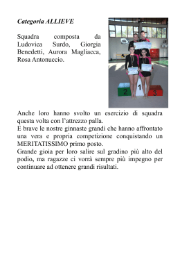
Manuale d’istruzione
Tr a u z i o n e d e l l e i n s t r u z i o n i o r i g i n a l i
Attrezzo oleopneumatico
T40 Installation Tool
Indice
Sicurezza
4
Specifiche tecniche
Ambito di utilizzo
Specifiche compressore
Dimensioni compressore
5
5
5
Messa in servizio
Principio di funzionamento
Preparazione all'impiego
Kit manicotti idraulici
Procedura operativa
6
6
6
7
Manutenzione
Istruzioni di smontaggio
Montaggio attrezzo
Procedura di spurgo
8
9
9
Schema generale attrezzo oleopneumatico
73414-02000
10
Elenco parti attrezzo oleopneumatico
73414-02000
11
Manutenzione del compressore
Quotidiana
Settimanale
Ogni 1200 ore di lavoro (almeno una volta all'anno)
Attrezzi di manutenzione
Scheda di sicurezza olio idraulico
12
12
12
12
12
Diagnostica
Malfunzionamento, causa probabile e rimedio
13-14
Garanzia
La garanzia di novanta giorni qui fornita è esclusiva, copre gli articoli fabbricati dal venditore
ed esclude espressamente qualsiasi altra garanzia esplicita o implicita comprese non a titolo
limitativo garanzie implicite di commerciabilità e idoneità a scopi particolari. Il venditore non
risponde di danni e perdite causati da ritardi o mancata consegna di ordini a causa di scioperi,
incendi, incidenti, società di trasporto o da qualsiasi altra ragione al di fuori del controllo del
venditore o dei suoi rifornitori. Le richieste di riparazione sotto garanzia devono essere
presentate al rivenditore per iscritto entro 90 giorni dalla data di spedizione. Non verranno
accettate restituzioni senza permesso scritto. A prescindere da altre disposizioni di cui alla
presente garanzia, il venditore non risponderà di perdite di utili aziendali o danni indiretti o
consequenziali sofferti dall'acquirente o da terzi in relazione agli articoli oggetto della
presente garanzia o al loro impiego, a prescindere dalle cause.
Garanzia
Il venditore dichiara espressamente di non fornire alcuna garanzia esplicita o implicita sulla
condizione, design, funzionamento, commerciabilità o idoneità all'uso di attrezzi o parti degli
stessi non fabbricati e/o forniti dal venditore stesso. Le uniche garanzie che coprono tali
attrezzi o parti degli stessi sono quelle fornite dal fabbricante degli stessi e il venditore si
impegna a collaborare con l'acquirente per far rispettare tali garanzie qualora necessario.
Il venditore si impegna a riparare o sostituire "franco a bordo" dai propri locali gli attrezzi o
parti degli stessi fabbricati dal venditore stesso quando venga provato che i relativi
malfunzionamenti siano dovuti a difetti della manodopera o dei materiali.
Avdel persegue una politica di continuo sviluppo e miglioramento dei propri prodotti e si riserva il diritto di cambiarne le specifiche senza preavviso.
3
S i c u re z z a
Il personale addetto alla messa in servizio, all'utilizzo e alla manutenzione del compressore deve conoscere a
fondo i contenuti del presente manuale e in particolare le seguenti norme di sicurezza.
1
Non utilizzare il compressore per scopi diversi da quelli previsti in sede di progettazione.
2
Utilizzare con il presente attrezzo esclusivamente gli accessori raccomandati da Avdel®.
3
L'utente si assume tutta responsabilità in relazione alle modifiche eventualmente apportate dallo stesso all'attrezzo.
4
Scollegare sempre l'attrezzo dal compressore hydrapac prima di regolare, smontare o montare la testata.
5
Non impiegare l'attrezzo se puntato verso altre persone.
6
Trovare una posizione ben stabile prima di utilizzare l'attrezzo.
7
Se l'attrezzo viene azionato senza la testata montata, fare attenzione a non toccare il perno di rilascio gambo e a non lasciar intrappolare
le dita tra il fermo del cannotto esterno (T304) e l'adattatore del cannotto interno (T307).
8
L'operatore e le persone in vicinanza devono indossare protezioni acustiche adeguate in quanto i livelli di rumorosità superano i limiti
permessi (vedi valori nelle specifiche tecniche a pag. 5).
9
Non impiegare tubi flessibili dalla pressione di esercizio inferiore a 10,000 psi (69 MPa).
10 La pressione di esercizio non deve superare gli 8,000 psi (55,2 mPa).
11 I gambi strappati dai rivetti ribaditi possono ferire le persone: fare attenzione.
12 Durante l'impiego dell'attrezzo si raccomanda all'operatore e alle persone in vicinanza di indossare occhiali protettivi.
13 Fare attenzione a non lasciare impigliare abiti, cravatte, capelli lunghi, stracci per la pulizia ecc. nelle parti in movimento dell'attrezzo.
14 Mantenere l'attrezzo pulito e asciutto in modo che possa essere impugnato saldamente.
15 Durante il trasporto dell'attrezzo tenere le mani lontane dal grilletto per evitare di avviarlo inavvertitamente.
16 Il compressore deve essere mantenuto in condizioni di sicurezza e ispezionato a intervalli regolari per verificare che non sia danneggiato e
funzioni a dovere da personale competente appositamente addestrato. Lo smontaggio può solo essere eseguito da personale
appositamente addestrato nelle relative procedure di Avdel®. Non smontare il compressore senza prima aver letto le istruzioni pertinenti.
Rivolgersi a Avdel® per informazioni sui corsi di formazione del personale necessari per la manutenzione della macchina.
17 Il compressore deve sempre essere utilizzato in conformità con le norme di sicurezza e sanità in vigore (nel Regno Unito: "Health & Safety
at Work Act 1974"). Rivolgersi a Avdel® per chiarire eventuali dubbi sull'utilizzo corretto della macchina.
ATTENZIONE
AVDEL RACCOMANDA DI COLLEGARE CON I PRESENTI ATTREZZI DI RIBADITURA SOLO COMPRESSORI HYDRAPAC IN
QUANTO COMPRESSORI DI ALTRE MARCHE POSSONO OPERARE A VALORI DI PRESSIONE DIVERSI DA QUELLI DI SICUREZZA
PREVISTI DAL FABBRICANTE.
PRIMA DI IMPIEGARE L'ATTREZZO ACCERTARSI CHE LE MANI DELL'OPERATORE ABBIANO SPAZIO A SUFFICIENZA.
TRATTARE L'ATTREZZO CON CURA: NON LASCIARLO CADERE NÉ USARLO COME MARTELLO.
IMPEDIRE CHE NEI CIRCUITI IDRAULICI DELL'ATTREZZO ENTRINO SPORCIZIA E CORPI ESTRANEI IN QUANTO CIÒ
PROVOCHEREBBE IL MALFUNZIONAMENTO DELL'ATTREZZO E DEL COMPRESSORE HYDRAPAC
4
S p e c i f i c h e Te c n i c h e
Ambito di Utilizzo
L'attrezzo T40 è costituito principalmente da un gruppo pistone e cilindro. Quando monta una testata compatibile e viene collegato
elettricamente e idraulicamente a un compressore, viene impiegato per installare rivetti da 1/2” a 3/4” Avdelok® e da 5/8” Avbolt® in
stabilimenti industriali.
Vedere la tabella qui sotto per l’elenco dei rivetti applicabili e delle relative testate.
Vedere i fogli dati elencati nella tabella per le istruzioni pertinenti alle testate.
RIVETTO
TIPO
MISURA
LD Avdelok ®
Avbolt
®
F O G L I O D AT I
D E L L A T E S TATA
T E S TATA
CODICE
DIM. ‘A’
CODICE
N32
110mm
07900-00919
73412-03200
N31
113mm
07900-00919
73412-03300
N30
131mm
07900-00919
73412-03400
N37
113mm
07900-00905
1/ ”
2
73412-03100
5/ ”
8
3/ ”
4
5/ ”
8
HAT REF.
Specifiche Compressore
Lunghezza
143 mm
5,6''
Diametro corpo
89 mm
3,5''
Altezza
203 mm
7,99''
Peso
8 kg
17,6 libbre
Corsa
41 mm
1,6''
Forza di trazione
175 kN
39340 lbf
Pressione trazione
55,2 MPa
8000 PSI
Pressione ritorno
20,7 MPa
3000 PSI
Olio idraulico
ISO VG 46 O EQUIVALENTE
Tipo rivetti
1/ ” a 3/ ” Avdelok® e da 5/ ” Avbolt®
2
4
8
Rumorosità
126,2 dB(A)
Potenza sonora
100,9 dB(A)
Vibrazione
8,6 m/sec3
Dimensioni Compressore
250 mm
190 mm
A
76 mm
5
Messa in Servizio
Principio di Funzionamento
AVVISO IMPORTANTE
Leggere attentamente le norme di sicurezza a pagina 4.
Una volta collegati entrambi i tubi e il cavo di controllo al compressore HydraPac, il ciclo di trazione e quello di ritorno dell'attrezzo
vengono avviati mediante pressione e rilascio del grilletto situato nel manico.
Premendo il grilletto viene eccitata l'elettrovalvola situata nel compressore HydraPac. Quest'ultima dirige l'olio idraulico pressurizzato
nel circuito di trazione del pistone dell'attrezzo. Ciò consente inoltre il ritorno nel serbatoio dell'olio presente nel circuito di ritorno
dell'attrezzo. Il gruppo pistone-cannotto interno si muove verso la parte posteriore dell'attrezzo consentendo al cuscino di spingere
l'anello mobile e le ganasce in avanti. Quando è presente un rivetto Avdelok® nella testata, il gruppo ganasce afferra il gambo e inizia
il ciclo di ribaditura.
Inizialmente vengono serrati gli strati da fissare, quindi con la continuazione del movimento del cannotto esterno il collare viene
pressato sulle scanalature di bloccaggio del perno. Alla fine della pressatura il cannotto esterno spinge con forza contro i componenti
da rivettare e il gambo viene spezzato.
Il grilletto deve essere immediatamente rilasciato una volta strappato il gambo: in questo modo l'elettrovalvola si diseccita cambiando
direzione al flusso dell'olio pressurizzato.
L'olio pressurizzato scorre ora nel circuito di ritorno dell'attrezzo e l'olio presente nel circuito di trazione torna nel serbatoio.
Grazie al movimento in avanti del gruppo pistone-cannotto interno, il rivetto installato viene rilasciato dal cannotto esterno, quindi (con
la continuazione del movimento) il meccanismo di rilascio apre le ganasce rilasciando il gambo spezzato, che viene espulso.
Quando il pistone torna nella posizione completamente avanzata, l'accumulo di pressione nel circuito provoca l'entrata del compressore
HydraPac nella modalità di attesa, mantenendo il congegno dell'attrezzo oleopneumatico in posizione avanzata. Una volta espulso il
gambo dalla testata, l'attrezzo è pronto per la prossima ribaditura.
Tener presente che tutti i compressori elettrici HydraPac entrano in modalità di riposo (cioè il motore elettrico si spegne
automaticamente) se il grilletto non viene premuto entro 25 secondi circa. Il compressore si riaccende automaticamente quando viene
ripremuto il grilletto. La modalità di riposo non è presente nei compressori HydraPac con motore diesel.
Preparazione All’impiego
• Attaccare la testata corretta all’attrezzo secondo le istruzioni nel foglio dati della testata pertinente.
• Accertarsi che il compressore HydraPac sia spento.
• Collegare i manicotti e il cavo di controllo al compressore HydraPac. L’attrezzo viene fornito con un manicotto di 0,7 m. Sono
disponibili altri manicotti idraulici di lunghezze differenti da ordinare separatamente se necessario. Vedere la tabella qui sotto per le
lunghezze disponibili e i relativi codici.
• Accendere il compressore HydraPac. Premere e rilasciare il grilletto alcune volte fino a quasi ultimare la corsa completa
dell'attrezzo per far circolare l'olio idraulico. Osservare il funzionamento dell'attrezzo. Verificare che non siano presenti perdite di
olio e che in modalità di attesa il pistone sia nella posizione completamente avanzata.
KIT MANICOTTI IDRAULICI
CODICE
07005-10014
07005-10034
07005-10035
6
LUNGHEZZA MANICOTTO
6 METRE
10 METRE
15 METRE
Messa in Servizio
P ro c e d u r a O p e r a t i v a
Installazione bulloni strutturali a strappo Avdelok®
• Controllare i componenti da rivettare ed eliminare la distanza eccessiva (cioè lo spazio) presente tra i diversi strati da fissare: la
distanza è eccessiva se la parte del gambo che fuoriesce dal collare non viene raggiunta dalle ganasce.
• Inserire la spina del rivetto Avdelok® nel foro.
• Inserire il collare del rivetto Avdelok® alla spina (l'estremità smussata del collare deve essere rivolta verso la testata e l'attrezzo).
• Coprire la spina con la testata e spingere quest'ultima finché il cannotto esterno non urta il collare. L'attrezzo e la testata devono
essere posizionati ad angolo retto (90°) rispetto ai componenti da rivettare.
• Premere il grilletto dell'attrezzo per avviare il ciclo di ribaditura.
• Quando il movimento in avanti del cannotto esterno della testata si interrompe e il gambo si spezza, rilasciare il grilletto: l'attrezzo
inizia il ciclo di ritorno staccandosi dal rivetto installato; alla fine della corsa di ritorno le ganasce rilasciano il gambo spezzato che
può essere eliminato inclinando in basso l'attrezzo.
• Una volta tolto il gambo spezzato, l'attrezzo e la testata sono pronti per il prossimo ciclo di ribaditura.
ATTENZIONE
NON CERCARE DI SPEZZARE IL GAMBO SENZA COLLARE INSTALLATO IN QUANTO CIÒ CAUSEREBBE L'ESPULSIONE
DALLA TESTATA AD ALTA VELOCITÀ E FORZA DELLA PORZIONE NON FISSATA DELLA SPINA DEL RIVETTO AVDELOK®.
7
Manutenzione
Istruzioni di Smontaggio
IMPORTANTE
Accertarsi che il compressore HydraPac sia spento prima di togliere l'attrezzo o la testata.
• Scollegare i due tubi idraulici 23 e il cavo di controllo 26.
• Svitare e togliere il cannotto esterno.
• Svitare il cannotto interno e togliere i componenti interni: ganasce, anello mobile ecc..
• Allentare la vite di fermo 7 e il cuscinetto 1 con una chiave a brugola da 4 mm.
• Svitare il fermo del cannotto esterno 1.
• Allentare la vite di ferno 7 sul fondello 19 usando una chiave di Allen da 4 mm.
• Svitare il fondello 19.
• Porre un contenitore sotto l'attrezzo per raccogliere l'olio.
• Se si dispone di una pompa manuale (73010-00001), collegarla al raccordo femmina e pompare lentamente facendo uscire il
pistone 10 dal cilindro 13.
• Altrimenti afferrare il pistone 10 in una morsa dalle ganasce morbide e far indietreggiare il cilindro 13 dando dei colpi leggeri con
una mazzuola morbida.
• Rimuovere il premistoppa posteriore 17 e l’anello di bloccaggio 16.
• Quando l’anello di bloccaggio 16 è stato rimosso, picchiettare il pistone 10 in avanti finché non esce.
• Rimuovere il premistoppa frontale 4 dal pistone 10.
• Rimuovere il pistone posteriore 15 dal cilindro 13.
• Ispezionare e sostituire le guarnizioni se necessario con il corredo di manutenzione SK40.
I numeri in grassetto si riferiscono allo schema generale e agli elenchi parti di cui alle pagine 10-11.
8
Manutenzione
Montaggio Attrezzo
Esaminare tutti i componenti e sostituire quelli usurati. Montare nuovi 'O' ring e anelli ausiliari (corredo di manutenzione SK40).
• Applicare olio idraulico a tutti gli 'O' ring, anelli ausiliari e superfici di contatto prima di rimontarli.
• Montare esternamente il nuovo O-Ring 3 e anello di supporto 2, montare internamente il nuovo anello di supporto 5 e O-Ring 6 sul
premistoppa frontale 4.
• Montare internamente il nuovo O-Ring 18 sul premistoppa posteriore 17.
• Montare l’O-Ring 8 e l’anello di supporto 9 sul pistone 10.
• Montare esternamente il nuovo O-Ring 8 e anello di supporto 9, montare internamente il nuovo anello di supporto 5 e O-Ring 6 sul
pistone posteriore 15.
• Montare internamente i nuovi anelli di supporto 11 e O-Ring 12 sul cilindro 13.
• Montare il pistone 10 nel cilindro 13.
• Installare il premistoppa frontale 4.
• Installare il fermo del cannotto esterno 1.
• Riserrare la vite di fermo 7 con una chiave a brugola da 4 mm.
• Inserire la molla 14 sul retro del pistone 10.
• Installare il pistone posteriore 15 seguito dall’anello di bloccaggio 16.
• Installare il premistoppa posteriore 17.
• Rimontare il fondello 19.
• Riserrare la vite di fermo 7 con una chiave a brugola da 4 mm.
• Spurgare l'attrezzo.
Procedura di spurgo
• Collegare i tubi corti dell'attrezzo direttamente a un compressore HydraPac o altro compressore compatibile.
Nota bene: non usare tubi prolunga in quanto impedirebbero all'aria di fuoriuscire nel compressore HydraPac.
• Installare un grilletto di regolazione HydraPac.
• Posizionare l'attrezzo in modo che il lato dell'asta del pistone sia rivolto verticalmente verso l'alto.
• Effettuare alcuni cicli di lavoro.
• Invertire la posizione verticale e rieffettuare altri cicli di lavoro.
I numeri in grassetto si riferiscono allo schema generale e agli elenchi parti di cui alle pagine 10-11.
9
S c h e m a G e n e r a l e A t t re z z o O l e o p n e u m a t i c o T 4 0
73414-02000
5
6
4
1
2
14
3
13
12*
11*
11*
20
10
19
7
8*
18*
9*
24
17
15
8*
5*
6*
16
7
9*
22
23
21
25
26
10
E l e n c o P a r t i A t t re z z o O l e o p n e u m a t i c o T 4 0
73414-02000
T40 ELENCO PARTI
PART.
CODICE
1
2
3
4
5
T404
E222
R222
T403
E123
6
7
8
9
10
11
12
13
14
15
16
17
18
19
20
21
22
23
24
25
26
R123
GS11
R226
I226
T402
E219
R219
T401
T409
T405
T406
T407
R217
T408
NG059
MS19
C084
HS02
HS01
C325
C106
DESCRIZIONE
FERMO CANNOTTO ESTERNO
ANELLO AUSILIARE
'O' RING
PREMISTOPPA POSTERIORE
ANELLO DI SUPPORTO
'O' RING
VITE DI FERMO
'O' RING
ANELLO DI SUPPORTO
PISTONE
ANELLO DI SUPPORTO
'O' RING
CILINDRO
MOLLA
PISTONE POSTERIORE
BIOCCAGGIO
PREMISTOPPA POSTERIORE
'O' RING
FONDELLO
90o ADATTATORE DEL MANICOTTO
GRILLETTO
IMPUGNATURA
TUBO IDRAULICO
SET RACCORDI AD ATTACCO RAPIDO
SPINA MASCHIO
CAVO DI CONTROLLO
QT.
CORREDO DI
MANUTENZIONE
1
1
1
1
2
2
2
2
2
1
2
1
1
1
1
1
1
1
1
1
1
1
2
1
1
1
*
*
*
*
*
*
*
*
*
* Gli 'O' ring e anelli ausiliari vengono forniti solo nel corredo di manutenzione SK40
11
M a n u t e n z i o n e d e l C o m p re s s o re
Quotidiana
•
Controllare che non ci siano perdite di olio.
•
Controllare la corsa dell'attrezzo.
•
Per verificare se il cannotto esterno è usurato, controllare se rimangono tacche o graffiature sul collare installato. Ciò può anche
essere confermato consultando i dati di installazione riportati nel catalogo del rivetto. L'usura eccessiva può causare la rottura
del cannotto esterno.
•
Verificare che la valvola di sicurezza della pressione di trazione funzioni correttamente.
Settimanale
•
Smontare e pulire la testata e in special modo le ganasce.
•
Controllare che non ci siano perdite di olio.
O g n i 1 2 0 0 O r e d i L a v o ro ( A l m e n o U n a Vo l t a A l l ’ a n n o )
L'attrezzo va smontato completamente e i componenti usurati sostituiti, compresi gli 'O' ring e gli anelli ausiliari.
Attrezzi Per la Manutenziobe
•
Chiavi a bocca da 17, 19, 24 mm
•
Chiavi a brugola da 4 mm, 6 mm
Scheda di Sicurezza Olio Idraulico
Pronto soccorso
CONTATTO CON PELLE
In condizioni normali non si verifica irritazione. Lavare comunque a fondo la zona interessata con acqua e sapone. Lavare gli abiti
sporchi di olio.
INGESTIONE
Se ingerito e la persona è cosciente, far bere acqua o latte. Non indurre il vomito a meno che non venga richiesto da personale
medico. Portare la persona che ha ingerito l'olio al centro sanitario più vicino.
CONTATTO CON GLI OCCHI
Irrigare con acqua immediatamente per alcuni minuti
VERSAMENTI ED ELIMINAZIONE
Eliminare i versamenti con materiale assorbente inerte e ventilare gli ambienti dove si sono verificati. Raccogliere i materiali
contaminati in contenitori usa e getta ed eliminare in modo conforme alle normative locali in materia.
Incendio
PUNTO DI INFIAMMABILITÀ: 200°C.
Sostanze estinguenti: polvere chimica secca, schiuma o anidride carbonica. Non estinguere in ambienti chiusi senza apparati
respiratori autonomi.
Maneggiamento
Applicare crema protettiva o indossare guanti resistenti all'olio.
Immagazzinaggio
Conservare al coperto e in modo conforme alle normative locali concernenti materiali infiammabili.
12
Diagnostica
MALFUNZIONAMENTO
L'attrezzo non funziona
CAUSA
PROBABILE
Il compressore HydraPac non è in funzione
RIMEDIO
PA G . R I F.
Verificare che il compressore HydraPac sia
collegato alla rete elettrica
Il cavo di controllo è lento o scollegato
Controllare che i fili non siano lenti né interrotti
Grilletto difettoso
Sostituire grilletto
Raccordi tubi idraulici difettosi
Sostituire raccordi difettosi
L'attrezzo perde olio
'O' ring difettosi o usurati; collegamenti tra tubi
Controllare e sostituire gli 'O' ring e gli anelli
idraulico
e attrezzo lenti
ausiliari oppure serrare il tubo idraulico
L'olio idraulico si
Strozzatura nel circuito idraulico
Controllare i raccordi e sostituirli se necessario
Pressione idraulica fornita bassa o variabile
Vedi manuale di istruzione compressore
surriscalda
1
L'attrezzo funziona a
tratti e non ribadisce i
rivetti correttamente
HydraPac
Pistone, 'O' ring e anelli ausiliari attrezzo
Sostituire l''O' ring e gli anelli ausiliari
difettosi o eccessivamente usurati
Usura eccessiva o graffiature presenti su
Controllare e sostituire i componenti difettosi
superfici di scorrimento dei componenti
dell'attrezzo
2
Le scanalature di presa
L'operatore non inserisce completamente la
Insegnare all'operatore la procedura di
del gambo del rivetto si
testata sul gambo del rivetto prima di azionare
installazione corretta
spanano durante la
l'attrezzo
corsa di trazione
Rivetto dalla lunghezza scorretta
Usare rivetti dalla lunghezza corretta
Sezioni ganasce usurate o danneggiate
Controllare e sostituire le ganasce
Schegge di metallo accumulate nelle
Pulire le sezioni delle ganasce
scanalature di presa delle sezioni delle ganasce
Distanza eccessiva tra i componenti da fissare
Eliminare la distanza eccessiva
Il collare del rivetto
Impiego scorretto dell'attrezzo
Vedi 2
Hydraloc non viene
Cannotto esterno testata usurato
Controllare e sostituire il cannotto esterno
L'attrezzo rimane
Impiego scorretto dell'attrezzo
Vedi 1
"impigliato" sui collari
Compressore HydraPac in modalità di attesa
Spegnere e riaccendere il compressore
completamente ribadito
ribaditi
HydraPac e riavviarlo premendo il grilletto
I gambi dei rivetti non
Scanalature di presa del rivetto spanate
Vedi 2
vengono strappati
Impiego scorretto dell'attrezzo
Insegnare all'operatore come impiegare
correttamente l'attrezzo
continua nella prossima pagina
13
Diagnostica
MALFUNZIONAMENTO
CAUSA
PROBABILE
RIMEDIO
Le sezioni delle
Funzionamento scorretto dell'anello mobile
Controllare lo stato di usura dei componenti
ganasce non
delle ganasce
interni del cannotto interno: ganasce, anello
mantengono la
mobile, cuscino e fondello. Pulire prima di
posizione corretta nel
rimontare.
cannotto interno
I raccordi idraulici
'O' ring difettoso o usurato nel raccordo
Sostituire 'O' ring e anello ausiliare
Montaggio scorretto della testata
Vedere la tabella della testata a pagina 5.
perdono olio
Il gambo non viene
rilasciato
14
PA G . R I F.
Dichiarazione di conformità
Noi, Avdel UK Limited; Watchmead Industrial Estate, Welwyn Garden City, Hertfordshire, AL7 1LY,
Gran Bretagna, dichiariamo sotto la nostra esclusiva responsabilità che il prodotto:
Modello: 73414-02000
No di serie:
................................................
al quale si riferisce la presente dichiarazione, è conforme ai seguenti standard:
EN ISO 12100 - parti 1 e 2
BS EN ISO 8662 - parte 6
BS EN ISO 11202
BS EN ISO 3744
BS EN 982
ISO EN 792 - parte 13-2000
BS EN 983
a norma delle disposizioni della Direttiva macchine 2006/42/EC
A. Seewraj - Responsabile Ingegneria della Produzione - Strumenti di Automazione
Data di emissione
La presente scatola contiene un attrezzo oleopneumatico
conforme alla direttiva relativa alle macchine
2006/42/EC. La "Dichiarazione di conformità" prevista è
contenuta internamente.
15
Since 1922
Since 1 936
2010
AUSTRALIA
Infastech (Australia) Pty Ltd.
891 Wellington Road
Rowville
Victoria 3178
Tel:
+61 3 9765 6400
Fax: +61 3 9765 6445
[email protected]
FRANCIA
Avdel France S.A.S.
33 bis, rue des Ardennes
BP4
75921 Paris Cedex 19
Tel:
+33 (0) 1 4040 8000
Fax: +33 (0) 1 4208 2450
[email protected]
CANADA
Avdel Canada Limited
1030 Lorimar Drive
Mississauga
Ontario L5S 1R8
Tel:
+1 905 364 0664
Fax: +1 905 364 0678
[email protected]
GERMANIA
Avdel Deutschland GmbH
Klusriede 24
30851 Langenhagen
Tel:
+49 (0) 511 7288 0
Fax: +49 (0) 511 7288 133
[email protected]
GIAPPONE
Infastech Kabushiki Kaisha
Center Minami SKY,
3-1 Chigasaki-Chuo, Tsuzuki-ku,
Yokohama-city,
Kanagawa Prefecture
Japan 224-0032
Tel:
+81 45 947 1200
Fax: +81 45 947 1205
[email protected]
CINA
Infastech (China) Ltd.
RM 1708, 17/F., Nanyang Plaza,
57 Hung To Rd., Kwun Tong
Hong Kong
Tel:
+852 2950 0631
Fax: +852 2950 0022
[email protected]
COREA DEL SUD
Infastech (Korea) Ltd.
212-4, Suyang-Ri,
Silchon-Eup, Kwangju-City,
Kyunggi-Do, Korea, 464-874
Tel:
+82 31 798 6340
Fax: +82 31 798 6342
[email protected]
Manual No.
07900-00909
INDIA
Infastech Fastening Technologies
India Private Limited
Plot No OZ-14, Hi Tech SEZ,
SIPCOT Industrial Growth Center,
Oragadam, Sriperumbudur Taluk,
Kanchipuram District,
602105 Tamilnadu
Tel:
+91 44 4711 8001
Fax: +91 44 4711 8009
[email protected]
Issue
Change Note No.
ITALIA
Avdel Italia S.r.l.
Viale Lombardia 51/53
20047 Brugherio (MI)
Tel:
+39 039 289911
Fax: +39 039 2873079
[email protected]
MALESIA
Infastech (Malaysia) Sdn Bhd
Lot 63, Persiaran Bunga Tanjung 1,
Senawang Industrial Park
70400 Seremban
Negeri Sembilan
+606 676 7168
Tel:
Fax: +606 676 7101
[email protected]
REGNO UNITO
Avdel UK Limited
Pacific House
2 Swiftfields
Watchmead Industrial Estate
Welwyn Garden City
Hertfordshire AL7 1LY
Tel:
+44 (0) 1707 292000
Fax: +44 (0) 1707 292199
[email protected]
SPAGNA
Avdel Spain S.A.
C/ Puerto de la Morcuera, 14
Poligono Industrial Prado Overa
Ctra. de Toledo, km 7,8
28919 Leganés (Madrid)
Tel:
+34 91 3416767
Fax: +34 91 3416740
[email protected]
TAIWAN
Infastech/Tri-Star Limited
No 269-7, Baodong Rd,
Guanmiao Township,
71841 Tainan County,
Taiwan, R.O.C
+886 6 596 5798 (ext 201)
Tel:
Fax: +886 6 596 5758
[email protected]
USA
Avdel USA LLC
614 NC Highway 200 South
Stanfield, North Carolina 28163
Tel:
+1 704 888 7100
Fax: +1 704 888 0258
[email protected]
SINGAPORE
Infastech (Singapore) Pte Ltd.
31 Kaki Bukit Road 3
#05-03/06 Techlink
Singapore, 417818
Tel:
+65 6372 5653
Fax: +65 6744 5643
[email protected]
Date
A
08/083
05/08
B
08/131
06/08
B2
11/061
03/11
Autosert® (equipment), Avbolt ®, Avdel®, Avdelmate ®, Avdel TX2000®, Avdelok®, Avex®, Avibulb ®, Avinox®, Avinut™, Avlug®, Avmatic®, Avplas®,
Avseal ®, Avsert®, Avtainer ®, Avtronic®, Briv®, Bulbex®, Chobert®, Eurosert®, Fastriv®, Finsert®, Genesis®, Grovit®, Hemlok®, Hexsert®, Holding
your world together®, Hydra®, Interlock®, Klamp-Tite ®, Klamptite KTR ®, Kvex®, Maxlok ®, Monobolt ®, Monobulb ®, Neobolt®, Nutsert®, Nutsert
SQ®, Portariv®, Rivmatic ®, Rivscrew®, Speed Fastening®, Squaresert®, Stavex®, Supersert®, Thin Sheet Nutsert ®, Titan®, T-Lok®, TLR®, TSN®,
TX2000®, Versa-Nut ®, Viking® e Viking 360® sono marchi di Avdel UK Limited. Infastech™ e Our Technology, Your Success™ sono marchi
di Infastech Intellectual Properties Pte Ltd. I nomi ed i loghi delle altre società qui menzionate possono essere marchi dei loro rispettivi
proprietari. Questo documento è solo a scopo informativo. Infastech non offre garazanzie, espresse o implicite, in questo documento. I dati
indicati sono soggetti a modifica senza preavviso come risultato della politica di continuo sviluppo e miglioramento del prodotto. Il vostro
rappresentante locale Avdel è a vostra disposizione se avete bisogno di confermare le ultime informazioni.
02.2011 • © 2010 Infastech
www.avdel-global.com
www.infastech.com
Instruction Manual
Original Instruction
T 4 0 I n s t a l l a t i o n To o l
H y d ro - E l e c t r i c P o w e r To o l
Contents
Safety
4
Specifications
Intent of Use
Tool Specification
Tool Dimensions
5
5
5
Putting into Service
Principle of Operation
Preparation for Use
Hydraulic Hose Kits
Operating Instructions
6
6
6
7
Maintenance
Dismantling Instructions
Assembling the Tool
To Bleed the Tool
8
8
9
General Assembly for T40 Installation Tool
73414-02000
10
Parts List for T40 Installation Tool
73414-02000
11
Servicing the Tool
Daily
Weekly
Every 1200 Working Hours (at least once a year)
Service Tools
Hydraulic Oil General Safety Data
12
12
12
12
12
Fault Diagnosis
Symptom, Possible Cause and Remedy
13-14
Warranty
The ninety day warranty herein expressed shall be the exclusive warranty on items
manufactured by seller and shall be in the place and stead of any other warranty, expressed or
implied, including but not limited to the implied warranties of merchantability and fitness for a
particular purpose.
Seller shall not be liable for any loss or damage resulting from delays or non-fulfilment or
orders owing to strikes, fires, accidents, transportation companies or for any reason or
reasons beyond the control of seller or its suppliers.
All warranty claims must be submitted to the seller in writing, within 90 days from date of
shipment, and no returns will be accepted without written permission.
Other provisions hereof notwithstanding, seller shall not be liable for any loss of business
profits or any incidental or consequential damages incurred by Buyer or any third person in
connection with the items or use thereof, however caused.
Tool Warranty
Seller expressly disclaims any warranty express or implied, as to the condition, design,
operation, merchantability or fitness for use of any tool, or part(s) thereof not manufactured by
seller. The only warranties made with respect to such tool or part(s) thereof are those made
by the manufacturer thereof and seller agrees to cooperate with buyer in enforcing such
warranties when such action is necessary. Seller agrees to repair or replace F.O.B. seller's
plant, any tool or part(s) thereof manufactured by it and proved to seller to be defective due to
faulty workmanship or material.
Avdel UK Limited policy is one of continuous product development and improvement and we reserve the right to change the specification of any product without prior notice.
3
Safety
This instruction manual must be read with particular attention to the following safety rules, by any person
installing, operating, or servicing this tool.
1
Do not use outside the design intent.
2
Do not use equipment with this tool/machine other than that recommended by Avdel UK Limited.
3
Any modification undertaken by the customer to the tool/machine shall be the customer’s entire responsibility.
4
Always disconnect the tool from the HydraPac before attempting to adjust, remove or fit the nose assembly.
5
Do not operate a tool/machine that is directed towards any person(s).
6
Always adopt a firm footing or a stable position before operating the tool/machine.
7
If cycling the tool without the nose assembly, care must be taken to avoid contact with the moving piston.
8
Ear protection must be worn by the operator and others in the vicinity as noise levels exceed the permitted maximum. For values
see Tool Specification on page 5.
9
Do not fit flexible hoses rated at less than 10,000 psi (69 mPa) working pressure.
10 The operating pressure shall not exceed 8,000 psi (55.2 mPa).
11 Care shall be taken to ensure that spent pintails are not allowed to create a hazard.
12 When using the tool, the operator and others in the vicinity are recommended to wear safety glasses.
13 Take care to avoid entanglement of loose clothes, ties, long hair, cleaning rags etc. in the moving parts of the tool.
14 The tool should be kept clean and dry for the best possible grip.
15 When carrying the tool from place to place keep hands away from the trigger to avoid inadvertent start up.
16 The machine must be maintained in a safe working condition at all times and examined at regular intervals for damage and function
by trained competent personnel. Any dismantling procedure shall be undertaken only by personnel trained in Avdel® procedures.
Do not dismantle the machine without prior reference to the maintenance instructions. Contact Avdel® with your training
requirements.
17 The machine shall at all times be operated in accordance with relevant Health and Safety legislation. In the UK the "Health & Safety
at Work Act 1974" applies. Any question regarding the correct operation of the machine must be directed to Avdel®.
CAUTIONS
AVDEL RECOMMENDS THAT ONLY HYDRAPAC UNITS BE USED TO DRIVE INSTALLATION TOOLS, AS OTHER MAKES OF
HYDRAULIC POWER UNITS MAY NOT OPERATE AT THE SAFE DESIGNED WORKING PRESSURES.
ENSURE THAT THERE IS ADEQUATE CLEARANCE FOR THE TOOL OPERATOR'S HANDS BEFORE PROCEEDING.
DO NOT ABUSE THE TOOL BY DROPPING OR USING IT AS A HAMMER.
KEEP DIRT AND FOREIGN MATTER OUT OF THE HYDRAULIC SYSTEMS OF THE TOOLS AS THIS WILL CAUSE THE TOOL AND
HYDRAPAC TO MALFUNCTION
4
Specifications
Intent of Use
The T40 Installation Tool is basically a Piston and Cylinder Assembly. When coupled Hydraulically and Electrically to a compatible
Hydraulic Power Source and the relevant Nose Assembly is attached, it is then used to install 1/2’’ to 3/4” Avdelok® and 5/8” Avbolt®
in industrial environments.
Refer to the table below for the list of applicable fasteners and associated nose equipment.
Refer to the datasheets listed in the table for the relevant nose assembly instructions.
FA S T E N E R
TYPE
N O S E A S S E M B LY
D ATA S H E E T
N O S E A S S E M B LY
SIZE
PART Nº
DIM. ‘A’
PART Nº
1/ ”
2
73412-03100
H AT REF.
N32
110mm
07900-00919
LD Avdelok ®
5/ ”
8
3/ ”
4
73412-03200
N31
113mm
07900-00919
73412-03300
N30
131mm
07900-00919
Avbolt ®
5/ ”
8
73412-03400
N37
113mm
07900-00905
To o l S p e c i f i c a t i o n
Length
250 mm
9.8 in
Body Diameter
76 mm
2.9 in
Height
190 mm
7.50 in
Weight
7 kg
15.5 lbs
Stroke
41 mm
1.6 in
Pull Force
175kN
39340lbf
Pull pressure
55.2 mPa
8000 PSI
Return Pressure
20.7 mPa
3000 PSI
Hydraulic Oil
ISO VG 46 OR EQUIVALENT
Fastener Range
1/ ’’ to 3/ ” Avdelok® and 5/ ” Avbolt®
2
4
8
Noise Level
126.2 dB(A)
Sound Power
100.9 dB(A)
Vibration
8.6 m/sec3
To o l D i m e n s i o n s
250 mm
190 mm
A
76 mm
5
Putting into Service
Principle of Operation
IMPORTANT
Read the safety rules on page 4 carefully
When both hoses and control cord are connected to the HydraPac, the pull and return cycles of the tool are controlled by depressing
and releasing the trigger switch located in the handle respectively.
When the switch is depressed the solenoid valve located in the HydraPac is energised and directs the pressurised oil flow to the pull
side of the piston in the tool. This also allows the oil in the return side of the tool to return to the tank. The piston/collet assembly now
moves towards the rear of the tool allowing the cushion to push the follower and jaws forward. If a Avdelok® pin has been inserted in
the nose for assembly, the jaw set will clamp onto the pintail and assembly will commence.
The cycle of installation will first clamp the joint to be fastened and then as the anvil continues to move forward the collar will be
swaged into the locking grooves of the pin. At the end of the swaging cycle the anvil will come hard up against the joint and as
movement continues the pintail will be broken off.
The trigger switch must be released immediately after pin break occurs. Releasing the trigger switch will cause the solenoid to deenergise and reverse the flow of pressurised oil.
Pressurised oil will now flow into the return side of the installation tool with the oil in the pull side returning to the tank.
The forward movement of the piston/collet assembly firstly ejects the installed fastener from the anvil and as the forward movement
continues, the jaw release mechanism will cause the jaws to open and release the broken off pintail, which will then be ejected.
When the piston returns to the fully forward position the pressure build up in the system will cause the Hydrapac to go into idle mode.
This keeps the installation tool in the forward position. Once the pintail has been ejected from the nose, the tool is ready for the next
installation.
Please note that with all electric HydraPacs there is a built in "Sleep Mode" which in effect means that the electric motor will
automatically switch off if the trigger switch is not operated for approximately 25 seconds. The HydraPac will automatically start up on
depression of the tool trigger switch. However the diesel HydraPac does not have a "Sleep Mode" and the diesel engine needs to be
switched off manually.
Preparation for Use
• Attach the correct nose assembly to the tool as per instructions in the relevant nose assembly data sheet.
• Ensure the HydraPac is not running.
• Connect hoses and the control cord to the HydraPac, the tool is supplied with a 0.7m hose length.
Additional hydraulic hose lengths are available to order separately as required. Refer to the table below for the available lengths and
associated part numbers.
• Start the HydraPac. Depress and release the trigger switch a few times to almost the full stroke of the tool to circulate hydraulic
fluid. Observe action of tool. Check for fluid leaks and ensure that in the idler mode the piston is in the fully forward position.
HYDRAULIC HOSE KITS
PART NUMBER
07005-10014
07005-10034
07005-10035
6
HOSE LENGTH
6 METRE
10 METRE
15 METRE
Putting into Service
Operating Instructions
To install a Avdelok® Fastener
• Check work and remove excessive gap. (Gap is the space between components of the Joint. Gap is excessive if not enough pintail
sticks through the collar for the nose assembly jaws to grab onto.)
• Put Avdelok® pin into hole.
• Slide Avdelok® collar over pin. (The bevelled end of the collar must be towards the nose assembly and tool.)
• Push nose assembly onto pin until the nose assembly anvil stops against the collar. Tool and nose assembly must be held at right
angles (90°) to the work.
• Depress tool trigger switch to start installation cycle.
• When the forward motion of the nose assembly anvil stops and the pintail breaks off, release the switch. The tool will go into its
return stroke and push off the installed fastener. At the end of the return stroke the jaws will release the expended pintail which can
be removed by tilting the tool down.
• Once the expended pintail has been ejected, the tool and nose assembly is ready for the next installation cycle.
CAUTION
DO NOT ATTEMPT TO BREAK OFF A PINTAIL WITHOUT THE INSTALLATION OF A COLLAR AS THIS WILL CAUSE THE
UNSECURED PORTION OF THE AVDELOK® PIN TO EJECT FROM THE NOSE AT A HIGH SPEED AND FORCE.
7
Maintenance
Dismantling Instructions
IMPORTANT
Be sure the HydraPac is turned off before removing tool or nose.
•
•
•
•
•
Uncouple the two Hydraulic Hoses 23 and disconnect Control Cord 26.
Unscrew and remove the anvil by hand.
Unscrew the collet and remove the inner assembly by hand.
Loosen Grub Screw 7 on Anvil Retainer 1 using a 4 mm Allen Key.
Unscrew Anvil Retainer 1.
• Loosen Grub Screw 7 on End Cap 19 using a 4 mm Allen Key.
• Unscrew End Cap 19.
•
•
•
•
•
•
Place a tray under the tool to catch the oil.
If a hand pump (73010-00001) is available, connect to female coupling and slowly pump Piston 10 out of Cylinder 13.
Otherwise clamp Piston 10 in a soft jawed vice and tap Cylinder 13 backwards with a soft mallet.
Remove Rear Gland 17 followed by removing Securing Ring 16.
When Securing Ring 16 is removed, tap Piston 10 forward until the piston is out.
Remove the Front Gland 4 from Piston 10.
• Remove Rear Piston 15 from Cylinder 13.
• Inspect and replace seals if necessary with Service Kit SK40.
A s s e m b l i n g t h e To o l
Examine and replace all worn parts. Fit new 'O' Rings and Back-up Rings (Service Kit SK40).
• Apply hydraulic oil to all 'O' rings, back-up rings and contact surfaces before fitting.
• Fit externally new ‘O' Ring 3 and Back-up Ring 2, fit internally new Back-up Ring 5 and ‘O’ Ring 6 to Front Gland 4.
• Fit internally new'O' Ring 18 to Rear Gland 17.
• Fit 'O' Ring 8 and Back-up Ring 9 to Piston 10.
• Fit externally new ‘O' Ring 8 and Back-up Ring 9, fit internally new Back-up Ring 5 and ‘O’ Ring 6 to Rear Piston 15.
• Fit internally new Back-up Rings 11 and ‘O’ Ring 12 into Cylinder 13.
• Install Piston 10 into Cylinder 13.
• Install Front Gland 4.
• Install Anvil Retainer 1.
• Re-clamp Grubscrew 7 using a 4 mm Allen Key.
• Insert Spring 14 onto rear of Piston 10.
• Install Rear Piston 15 followed by Securing Ring 16.
• Install Rear Gland 17.
• Refit End Cap 19.
• Re-clamp the Grubscrew 7 using a 4 mm Allen Key.
• Bleed the Tool.
Item numbers in bold refer to the general assembly drawing and parts list on pages 10-11.
8
Maintenance
To B l e e d t h e To o l
To Bleed the Tool:
• Couple the short tool hoses directly onto a HydraPac or compatible hydraulic power source.
Note:
Do not use long extension hoses as these will prevent the air from escaping into the HydraPac.
• Plug in a HydraPac Test Trigger.
• Position the tool so that the piston rod side faces vertically up.
• Cycle a few times.
• Reverse the vertical position and cycle again.
9
G e n e r a l A s s e m b l y f o r T 4 0 I n s t a l l a t i o n To o l
73414-02000
5
6
4
1
2
14
3
13
12*
11*
11*
20
10
19
7
8*
18*
9*
24
17
15
8*
5*
6*
16
7
9*
22
23
21
25
26
10
P a r t s L i s t f o r T 4 0 I n s t a l l a t i o n To o l
73414-02000
T40 INSTALLATION TOOL PARTS LIST
ITEM
PART Nº
1
2
3
4
5
T404
E222
R222
T403
E123
6
7
8
9
10
11
12
13
14
15
16
17
18
19
20
21
22
23
24
25
26
R123
GS11
R226
I226
T402
E219
R219
T401
T409
T405
T406
T407
R217
T408
NG059
MS19
CO84
HS02
HS01
C325
C106
DESCRIPTION
QTY SERVICE KIT
ANVIL RETAINER
BACK-UP RING
'O' RING
FRONT GLAND
BACK-UP RING
1
1
1
1
2
ëO ’ RING
GRUB SCREW
'O' RING
BACK-UP RING
PISTON
BACK-UP RING
'O' RING
CYLINDER
SPRING
REAR PISTON
SECURING RING
REAR GLAND
'O' RING
END CAP
90 HOSE ADAPTOR
TRIGGER SWITCH
HANDLE
HYDRAULIC HOSE
QUICK COUPLER SET
MALE PLUG
CONTROL CORD
2
2
2
2
1
2
1
1
1
1
1
1
1
1
1
1
1
2
1
1
1
*
*
*
*
*
*
*
*
*
*'O' Rings and Back-up Rings only supplied in Service Kit SK40.
11
S e r v i c i n g t h e To o l
Daily
•
Check for oil leaks.
•
Check the stroke of tool.
•
Check for worn anvil indicated by score marks on the installed collar. This can also be confirmed by referring to the installed data
in the fastener catalogue. Excessive wear can cause the anvil to rupture.
•
Check function of pull pressure safety valve.
We e k l y
•
Dismantle and clean the nose assembly especially the jaws.
•
Check for oil leaks.
Every 1200 working hours (at least once a year)
The tool should be completely dismantled and worn components replaced including 'O' rings and back-up rings.
S e r v i c e To o l s
•
Open Ended Flat Spanners - 17, 19, 24 mm
•
Allen Keys - 4 mm, 6 mm
Hydraulic Oil General Safety Data
First Aid
SKIN:
Under normal conditions skin irritation will not occur, contaminated skin should however be washed thoroughly with soap and water.
Launder contaminated clothing.
ORAL:
If swallowed and person is conscious give water or milk. Do not induce vomiting unless on advice of medical personnel. Take person
to nearest medical centre.
EYES:
Flush immediately with water for several minutes
DISPOSAL:
Remove all spills with inert absorbent material. Ventilate spill area. Place contaminated materials in a disposable container and
dispose in a manner consistent with local regulations.
Fire
FLASH POINT: 200°C.
Extinguish with either dry chemical, foam or carbon dioxide. Do not enter confined space without self contained breathing apparatus.
Handling
Use barrier cream or oil resistant gloves.
Storage
Undercover and consistent with local regulations for inflammable material.
12
Fault Diagnosis
Symptom
Tool fails to operate
Possible Cause
Remedy
Inoperative HydraPac
Check power supply to HydraPac
Loose or disconnected control cord
Check for loose or broken wires
Defective switch assembly
Replace switch assembly
Faulty hydraulic hose couplings
Replace faulty couplings
Tool leaks hydraulic
Depending on what leaks occur,
Check and replace 'O' rings
oil
defective or worn 'O' rings, loose
and back-up rings, or
hydraulic hose connections at tool
tighten hydraulic hose
Restriction in hydraulic line
Check couplings and replace
Hydraulic oil
overheats
Page Ref
if necessary
1
Tool operates
Low or erratic hydraulic
See HydraPac instruction
erratically and fails
pressure supply
manual
to install fastener
Defective or excessively worn
Replace 'O' ring and back-up
piston, 'O' ring and back-up rings
rings
properly
and back-up rings in tool
Excessive wear or scoring of
Check and replace defective
sliding surface of tool parts
parts
2
Pull grooves on
Operator not pushing nose
Instruct operator in proper
fastener pintail
completely onto fastener pintail
installation methods
stripped during pull
before operating tool
stroke
Incorrect fastener length
Use correct length fastener
Worn or damaged jaw segments
Check and replace jaw set
Metal chips accumulated in pull
Clean jaw segments
grooves of jaw segments
Excessive sheet gap
Eliminate excessive gap
Collar of Hydraloc
Improper tool operation
See 2
fastener not
Worn anvil in nose
Check and replace anvil
Tool "hang up" on
Improper tool operation
See 1
swaged collar
Hydrapac in idler mode
completely swaged
Switch HydraPac off and
on and restart by
depressing trigger switch
Pintail of fastener
Pull grooves on fastener stripped
fails to break
Improper tool operation
See 2
Instruct operator in correct
tool operation
continued overleaf
13
Fault Diagnosis
Symptom
Possible Cause
Remedy
Jaw segments do not Improper operation of jaw
Check internal parts of the
maintain proper
collet for wear i.e. jaws,
follower
position in collet
follower, cushion and end cap.
Clean before reassembling
14
Hydraulic couplers
Defective or worn 'O' ring in
leak oil
coupler body
Pintail fails to release
Incorrect assembly of Nose
Replace 'O' ring and back-up ring
Refer to nose assembly table on page 5
Page Ref
Declaration of Conformity
We, Avdel UK Limited, Watchmead Industrial Estate, Welwyn Garden City, Herts, AL7 1LY
declare under our sole responsibility that the product:
Model: 73414-02000
Serial No.
................................................
to which this declaration relates is in conformity with the following standards:
EN ISO 12100 - parts 1 & 2
BS EN ISO 8662 - part 6
BS EN ISO 11202
BS EN ISO 3744
BS EN 982
ISO EN 792 part 13 - 2000
BS EN 983
following the provisions of the Machine Directive 2006/42/EC
A. Seewraj - Product Engineering Manager - Automation Tools
Date of issue
This box contains a power tool which is in
conformity with Machines Directive
2006/42/EC. The ‘Declaration of Conformity’
is contained within.
15
Since 1922
Since 1 936
2010
AUSTRALIA
Infastech (Australia) Pty Ltd.
891 Wellington Road
Rowville
Victoria 3178
Tel:
+61 3 9765 6400
Fax: +61 3 9765 6445
[email protected]
GERMANY
Avdel Deutschland GmbH
Klusriede 24
30851 Langenhagen
Tel:
+49 (0) 511 7288 0
Fax: +49 (0) 511 7288 133
[email protected]
INDIA
Infastech Fastening Technologies
India Private Limited
Plot No OZ-14, Hi Tech SEZ,
SIPCOT Industrial Growth Center,
Oragadam, Sriperumbudur Taluk,
Kanchipuram District,
602105 Tamilnadu
Tel:
+91 44 4711 8001
Fax: +91 44 4711 8009
[email protected]
CANADA
Avdel Canada Limited
1030 Lorimar Drive
Mississauga
Ontario L5S 1R8
Tel:
+1 905 364 0664
Fax: +1 905 364 0678
[email protected]
CHINA
Infastech (China) Ltd.
RM 1708, 17/F., Nanyang Plaza,
57 Hung To Rd., Kwun Tong
Hong Kong
Tel:
+852 2950 0631
Fax: +852 2950 0022
[email protected]
ITALY
Avdel Italia S.r.l.
Viale Lombardia 51/53
20047 Brugherio (MI)
Tel:
+39 039 289911
Fax: +39 039 2873079
[email protected]
FRANCE
Avdel France S.A.S.
33 bis, rue des Ardennes
BP4
75921 Paris Cedex 19
Tel:
+33 (0) 1 4040 8000
Fax: +33 (0) 1 4208 2450
[email protected]
Manual No.
07900-00909
JAPAN
Infastech Kabushiki Kaisha
Center Minami SKY,
3-1 Chigasaki-Chuo, Tsuzuki-ku,
Yokohama-city,
Kanagawa Prefecture
Japan 224-0032
Tel:
+81 45 947 1200
Fax: +81 45 947 1205
[email protected]
Issue
Change Note No.
MALAYSIA
Infastech (Malaysia) Sdn Bhd
Lot 63, Persiaran Bunga Tanjung 1,
Senawang Industrial Park
70400 Seremban
Negeri Sembilan
+606 676 7168
Tel:
Fax: +606 676 7101
[email protected]
TAIWAN
Infastech/Tri-Star Limited
No 269-7, Baodong Rd,
Guanmiao Township,
71841 Tainan County,
Taiwan, R.O.C
+886 6 596 5798 (ext 201)
Tel:
Fax: +886 6 596 5758
[email protected]
SINGAPORE
Infastech (Singapore) Pte Ltd.
31 Kaki Bukit Road 3
#05-03/06 Techlink
Singapore, 417818
Tel:
+65 6372 5653
Fax: +65 6744 5643
[email protected]
UNITED KINGDOM
Avdel UK Limited
Pacific House
2 Swiftfields
Watchmead Industrial Estate
Welwyn Garden City
Hertfordshire AL7 1LY
Tel:
+44 (0) 1707 292000
Fax: +44 (0) 1707 292199
[email protected]
SOUTH KOREA
Infastech (Korea) Ltd.
212-4, Suyang-Ri,
Silchon-Eup, Kwangju-City,
Kyunggi-Do, Korea, 464-874
Tel:
+82 31 798 6340
Fax: +82 31 798 6342
[email protected]
USA
Avdel USA LLC
614 NC Highway 200 South
Stanfield, North Carolina 28163
Tel:
+1 704 888 7100
Fax: +1 704 888 0258
[email protected]
SPAIN
Avdel Spain S.A.
C/ Puerto de la Morcuera, 14
Poligono Industrial Prado Overa
Ctra. de Toledo, km 7,8
28919 Leganés (Madrid)
Tel:
+34 91 3416767
Fax: +34 91 3416740
[email protected]
Date
A
08/083
05/08
B
08/131
06/08
B2
11/061
03/11
Autosert® (equipment), Avbolt ®, Avdel®, Avdelmate ®, Avdel TX2000®, Avdelok®, Avex®, Avibulb ®, Avinox®, Avinut™, Avlug®, Avmatic®, Avplas®,
Avseal ®, Avsert®, Avtainer ®, Avtronic®, Briv®, Bulbex®, Chobert®, Eurosert®, Fastriv®, Finsert®, Genesis®, Grovit®, Hemlok®, Hexsert®, Holding
your world together®, Hydra®, Interlock®, Klamp-Tite ®, Klamptite KTR ®, Kvex®, Maxlok ®, Monobolt ®, Monobulb ®, Neobolt®, Nutsert®, Nutsert
SQ®, Portariv®, Rivmatic ®, Rivscrew®, Speed Fastening®, Squaresert®, Stavex®, Supersert®, Thin Sheet Nutsert ®, Titan®, T-Lok®, TLR®, TSN®,
TX2000®, Versa-Nut ®, Viking® and Viking 360 ® are trademarks of Avdel UK Limited. Infastech™ and Our Technology, Your Success™ are
trademarks of Infastech Intellectual Properties Pte Ltd. The names and logos of other companies mentioned herein may be trademarks
of their respective owners. This document is for informational purposes only. Infastech makes no warranties, expressed or implied, in this
document. Data shown is subject to change without prior notice as a result of continuous product development and improvement policy.
Your local Avdel representative is at your disposal should you need to confirm latest information.
02.2011 • © 2010 Infastech
www.avdel-global.com
www.infastech.com
Scaricare