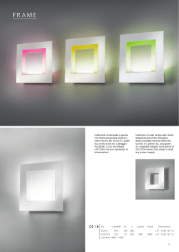
TECHNICAL DATA DIMENSIONI/SCHEMA ELETTRICO TECHNICAL DATA DIMENSIONS/WIRING DIAGRAM FISSAGGIO ALL’ATTUATORE Type LTL-287 LTL-359 LTL-431 LTL-503 L 289 361 433 505 L1 287 359 431 503 brn 1 wht 2 blk 4 blu 3 A. L+ IA (4 ... 20 mA) UA (0 ... 10 V) M L = Lunghezza totale / Total lenght L1 = Range di misura / Measuring range TECHNICAL DATA TECHNICAL DATA Indicatore di stato 1 / Status indicator 1 Indicatore di stato 2 / Status indicator 2 Pulsante Teach pad / Control panel TECHNICAL DATA Posizionare le staffe di fissaggio (cod. W0950000721) in una delle cave a T presenti sulla camicia del cilindro ; B. Inserire le staffe di fissaggio nella cava del trasduttore avendo cura di fissarle ad una distanza minima di 30 mm rispetto alle estremità del trasduttore. C-D. Le staffe di fissaggio permettono una regolazione della posizione oltre che lungo l’asse dello stelo anche in direzione perpendicolare rispetto alla cava a T. In questo modo si può fissare il trasduttore il più centrale possibile; A. Position the brackets (code W0950000721) in one of the T-slots in the cylinder liner. B. Fix the brackets in the transducer slot at least 30 mm from the ends of the transducer. C-D. The brackets are used to adjust the position along the axis of the piston rod, including perpendicular to the T-slot. This allows you to fix the transducer in as central a position as possible. 30 min DATI TECNICI Campo di misura corsa (± 1 mm) TECHNICAL DATA Alimentazione DATA TECHNICAL Ondulazione residua Vpp Tempo di campionamento di lettura della posizione Risoluzione Errore di linearità tipica Ripetibilità 2 Velocità corsa nominale, tipica 2 3 Velocità corsa completa, tipica 2 4 Uscita analogica (corrente) Uscita analogica (tensione) Uscita analogica fuori range (corrente) TECHNICAL DATA Uscita analogica fuori range (tensione) TECHNICAL DATA Protezione contro il cortocircuito Protezione contro l’inversione di polarità Resistenza di carico (uscita corrente) Resistenza di carico (uscita tensione) Corrente di riposo (senza carico) 2 Classe di protezione Grado di protezione EMC Shock test IEC 60068-2-6 Test di vibrazione IEC 60068-2-6 Temperatura ambiente TECHNICAL DATA FIXING ON THE ACTUATOR TECHNICAL DATA mm ms mm m/s m/s mA V mA V Ω Ω mA °C 287-359-431-503 15 ... 30 VDC 1 < 10 % di UB 1.15 0.03 % FSR (≥ 0.05 mm) 0.5 0.06 % FSR (≥ 0.1 mm) < 1.5 <3 4 ... 20 0 ... 10 3 11 SI SI < 500 > 2000 < 35 III IP 67 / IP 65 according to EN 60947-5-7 30 g/11 ms 10 ... 55 Hz/1 mm -20 ÷ +70 1 Funzionamento in rete con protezione dai cortocircuiti max. 8 A 2 T = 25 °C, UB = 24 V 3 Campo di misura fisico max. < corsa di lavoro (campo magnetico anche al di fuori del rilevamento max.) 4 Campo di misura fisico max. > corsa di lavoro (campo magnetico a rilevamento costante) FSR: Full Scale Range, campo di misura max con una potenza del campo compresa tra 2 mT e 15 mT In caso di interferenze transitorie ci possono essere delle variazioni del valore di misura TECHNICAL DATAanalogico Measuring range (± 1 mm) Voltage Residual ripple VPP Sample time Resolution Linearity error type Repeatability 2 Partial stroke speed, type 2 3 Full stroke speed, type 2 4 Analoge output (current) Analoge output (voltage) Uscita analogica fuori range (corrente) Uscita analogica fuori range (tensione) Short-circuit protection Polarity inversion protection Load resistance (current output) Load resistance (voltage input) Closed current (without load) 2 Protection class Enclosure rating EMC IEC 60068-2-6 shock test IEC 60068-2-6 vibration test Ambient temperature mm ms mm m/s m/s mA V mA V Ω Ω mA °C 287-359-431-503 15 ... 30 VDC 1 < 10 % from UB 1.15 0.03 % FSR (≥ 0.05 mm) 0.5 0.06 % FSR (≥ 0.1 mm) < 1.5 <3 4 ... 20 0 ... 10 3 11 YES YES < 500 > 2000 < 35 III IP 67 / IP 65 according to EN 60947-5-7 30 g/11 ms 10 ... 55 Hz/1 mm -20 ÷ +70 NOTE NOTES 1 Operation in short-circuit protected network max. 8 A 2 T = 25 °C, UB = 24 V 3 Physical max. measuring range < working stroke (magnetic field also outside the max.coverage) 4 Physical max. measuring range > working stroke (magnetic field is always recorded) FSR: Full scale range, max. measuring range at field strength 2 mT to 15 mT The analog measured value can deviate under transient conditions MANUALE D’USO TRASDUTTORE DI POSIZIONE MAGNETICO CON USCITA ANALOGICA SERIE LTL TECHNICAL DATA I www.metalwork.eu ZVAACF002 ITA_GB - IM02 - 07/2014 MAGNETIC POSITION SENSOR WITH ANALOG OUTPUT SERIES LTL USER MANUAL GB AVVERTENZE DI SICUREZZA SAFETY SPECIFICATIONS L eggere le istruzioni per l’uso prima della messa in esercizio. Collegamento, montaggio e regolazione solo da parte di personale qualificato. Non è un componente di sicurezza secondo la Direttiva macchine EN. Utilizzare una fonte di corrente conforme alla norma IEC/DIN EN 60204-1. Per il collegamento utilizzare cavi totalmente schermati e in generale rispettare le regole generali di collegamento e utilizzo dei segnali analogici. MODALITÀ D’IMPIEGO Read the operating instructions before starting operation. Connection, assembly, and settings only by competent technicians. This is not a component in accordance with EU machine guidelines. Use a power source according to IEC/DIN EN 60204-1. Use fully shielded connecting cables and follow the general rules for connecting and using analogue signals. PROPER USE L’LTL è un trasduttore magnetico di posizione ed è progettato per la misurazione del percorso lineare su trasmissioni pneumatiche. Per il montaggio sul cilindro si consiglia di utilizzare gli appositi dispositivi di fissaggio. Per garantirne il corretto funzionamento, è necessaria un’intensità di campo magnetico compresa tra 2 mT e 15 mT. Oltre questi limiti i dati delle specifiche non sono garantiti. Osservare gli indicatori del campo magnetico: - Potenza campo magnetico ottimale: in presenza di un campo magnetico ottimale il LED1 (giallo) resta acceso all’interno dell’area di misura. - Potenza campo magnetico non ottimale: in presenza di un campo magnetico debole il LED1 (giallo) resta acceso all’interno dell’area di misura. Il LED1 (rosso), inoltre, lampeggia. La funzione di misura e l’uscita sono attive, ma i dati caratteristici potrebbero non rientrare nelle specifiche. La posizione del pistone viene rilevata senza contatto. Il trasduttore dispone sia di un’uscita in tensione analogica (0 ... 10 V) sia di un’uscita in corrente analogica (4 ... 20 mA). Il trasduttore attiva solo l’uscita che viene cablata. Inoltre il trasduttore presenta la funzione “Fuori Range di misura” definito rispettivamente con: un segnale di tensione pari a 11 V quando è cablata l’uscita in tensione; un segnale di corrente pari a 3 mA quando è cablata l’uscita in corrente (vedi grafico ). Il Teach pad consente di impostare in modo esatto il campo di misura desiderato. (Vedere “Messa in esercizio” ! 1). L’impostazione del campo di misura non è necessariamente obbligatoria. In assenza di un’impostazione specifica del campo di misura, viene impiegato automaticamente il campo di misura massimo possibile. Il Teach-in del punto zero e del punto finale può essere effettuato indipendentemente dalla polarità del campo magnetico e dalla posizione del pistone. The LTL is a magnetic position sensor and is intended for linear path measurement on pneumatic drives. For mounting on the cylinder it is recommended that the relevant securing methods be used. A magnetic field strength between 2 mT and 15 mT is required in order to ensure a smooth function. Outside these limits, the specifications data cannot be guaranteed. Note the magnetic field indication: Magnetic field strength at optimum level: The magnetic field is at its optimum level, LED 1 (yellow) is continuously illuminated within the measuring range. Magnetic field strength not at optimum level: When the magnetic field is weak, LED 1 (yellow) is continuously illuminated within the measuring range. In addition, LED 1 (red) is flashing. The measurement function and output are active, but the characteristic data may be outside specification. The piston position is recorded contact-free. The sensor is equipped with an analog voltage output (0 ... 10 V) as well as an analog current output (4 ... 20 mA). The sensor only activates the wired output. The sensor also has an Out-of-Range Measurement function, which is defined by an 11V signal when the voltage output is wired and by a 3mA signal when the current output is wired (see graph ). The Teach Pad allows the required measuring range to be precisely set. (See starting operating! 1). Setting the measuring range is not mandatory. The maximum possible measuring range is used as standard if you do not teach-in a measuring range. The Zero Point and End Point can be taught independent of the magnetic field polarity and the piston position. LED 1 – giallo INDICATORE On statico Intermittente (3 Hz) Spento LED 1 – yellow Spento 1 – red 1 – rosso 1 – giallo e rosso 2 – verde 2 – blu FUNZIONE Misurazione Teach Alimentazione di tensione assente/ pistone fuori dal campo di misura Alimentazione di tensione assente/ nessun errore Errore di sensore interno Campo magnetico debole/qualità del segnale ridotta Configurazione in corso Uscita di tensione configurata Alimentazione di tensione assente Configurazione in corso Uscita di corrente configurata Alimentazione di tensione assente On statico Alternato Intermittente (3 Hz) On statico Spento Intermittente On statico Spento 1 – yellow and red 2 – green 2 – blue FUNCTION Measuring operation Teach No power supply/piston notin the measuring range No power supply/no errors DISPLAY Permanently On Flashes (3 Hz) Off Internal sensor error Weak magnetic field/reduced signal quality Configuration running Voltage output configured No power supply Configuration running Current output configured No power supply Permanently On Alternating Off Flashes (3 Hz) Permanently on Off Flashes Permanently On Off MESSA IN ESERCIZIO STARTING OPERATION 1Teach-in del campo di misura – Collegare il trasduttore alla tensione di esercizio, cablare opportunamente l’uscita analogica in corrente o in tensione desiderata (vedere schema elettrico) e fissare il trasduttore con accessori idonei (osservare le istruzioni per l’uso in allegato agli accessori). – Collocare il pistone nella posizione di partenza desiderata. Il LED 1 si illumina quando il pistone si trova nel campo di misura. Esercitare sul pulsante Teach pad un doppio click di cui il secondo deve durare per 2 s finché il LED 1 lampeggia in giallo e, successivamente, rilasciare. La posizione di partenza è memorizzata. – Portare la posizione del pistone nella posizione finale desiderata. Esercitare una breve pressione sul pulsante Teach pad (< 1 s). Il LED 1 si illumina di giallo, il punto finale nel campo di misura viene memorizzato. All’inizio della messa in esercizio, l’indicatore In-range del segnale di ricezione può essere tremolante. Ciò significa che il trasduttore è ancora in fase adattamento al campo magnetico. Se l’utente non imposta un campo di misura, viene impiegato automaticamente il campo di misura massimo possibile. Mediante la procedura di Teach, è possibile migliorare la definizione, comunque fino a un massimo di 60 µm. Avvertenza: -Se il punto di partenza si trova al di fuori del campo di misura, la procedura di impostazione viene interrotta. In questo caso il LED 1 lampeggia a intervalli brevi. -Qualsiasi procedura di impostazione incompleta viene interrotta dopo 90 s (time out). Resta attivo il campo di misura memorizzato più recentemente. -Ogni qualvolta il trasduttore viene trasferito su un altro attuatore è consigliabile effettuare un ciclo di ripristino prima di effettuare un nuovo ciclo di Teach-in (vedi punto 4). 2 Controllo del campo di misura impostato Far scorrere il pistone/magnete e verificare il campo di misura mediante il LED 1 giallo oppure verificare l’uscita analogica (vedi nota fuori range). Correggere, se necessario, il campo di misura desiderato tramite una nuova procedura di Teach-in. 3Selezionare l’uscita di corrente o di tensione – Esercitare sul pulsante Teach pad un doppio click di cui il secondo deve durare per 5 s, finché il LED 2 lampeggia e, successivamente, rilasciare. – Toccare brevemente il pulsante Teach pad (< 2 s), per passare da Uout (LED 2 lampeggia in verde) a Iout (LED 2 lampeggia in blu). – Per terminare l’impostazione, esercitare pressione più a lungo sul pulsante Teach pad (> 2 s). 4 Ripristinare il campo di misura impostato in fabbrica: – Premere brevemente il pulsante Teach pad, tenere premuto per 8 s finché entrambi i LED lampeggiano e, successivamente, rilasciare. Il LED 1 lampeggia in giallo, i dati non sono ancora stati resettati. – Esercitare una breve pressione sul pulsante Teach pad – Le posizioni preimpostate sono state ripristinate. 1Teach-in the measuring range – Connect the sensor to the operating voltage and connect the desired current or voltage analog output (see wiring diagram) and secure with appropriate accessories (the assembly instructions enclosed with the accessories must be followed). – Set pistons to the required zero point position. The LED is illuminated if the piston is in the measuring range. Briefly tap on the control panel, hold for 2 s until the LED 1 flashes yellow and then release. The zero point is saved. The in-range display may flicker at the start of commissioning. This indicates that the magnet field is still being taught-in on the sensor. – Set piston position to the required end position. Briefly tap on the control panel (< 1 s). The LED 1 is illuminated (yellow), the measuring range end point is saved. The maximum possible range is used as standard if the user does not teach-in the measuring range. The teach-in process can be used to increase the resolution, but only to a maximum of 60 µm. Note: The teach-in process is aborted if the zero point is located outside the measuring range. In this case the LED 1 flashes at short intervals. - If the teach-in process is incomplete, it is aborted after 90 s (time- out). The measuring range saved previously remains active. The in-range display may flicker at the start of commissioning. - When the sensor is transferred to another actuator, it is advisable to activate a reset cycle before starting a new Teach-in cycle (see point 4). 2Check the taught-in measuring range Move the piston and review the set measuring range based on the yellow LED. If necessary, correct the required m easuring range via a new teach-in process. 3Select current or voltage output – Briefly tap the control panel then hold for 5 s until the LED 2 flashes then release. – Briefly touch the control panel (< 2 s) in order to switch between Uout (LED 2 flashes green) and Iout (LED 2 flashes blue). – Hold down on the control panel (> 2 s) in order to quit out of the setting. 4Reset the measurement range to the ex works setting: – Briefly tap on the control panel, hold for 8 s until both LEDs flash then release. The LED 1 now flashes yellow, it has not been reset. – Briefly tap the control panel – The taught-in positions have now been reset. TECHNICAL DATA TECHNICAL DATA A TECHNICAL DATA TECHNICAL DATA 2 TECHNICAL DATA TECHNICAL DATA 2a TECHNICAL DATA TECHNICAL DATA Out of range Out of range Out of range Out of range TECHNICAL DATA TECHNICAL DATA 3 TECHNICAL DATA Giallo/yellow, TECHNICAL DATA In-Range Blu/blue, Iout Verde/green, Uout MANUTENZIONE I trasduttori di posizione non richiedono manutenzione. Si consiglia di controllare regolarmente i collegamenti elettrici. Qualsiasi colore/any color LED lampeggiante (3 Hz)/LED flashes (3 Hz) MAINTENANCE Magnetic position sensors do not require any maintenance, but the electrical connections should be checked regularly 6
Scaricare