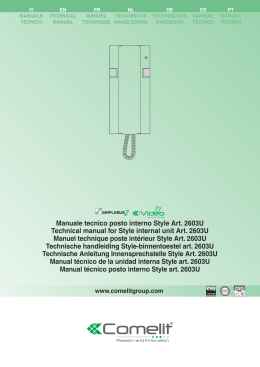
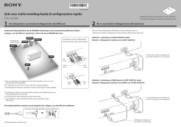
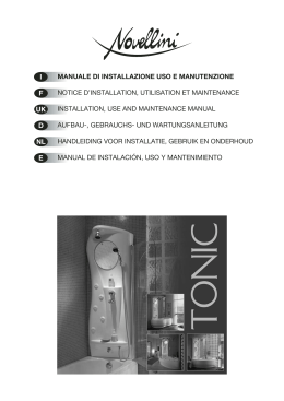
F E I NL GB D ise smart connect KNX Vaillant ise smart connect KNX Vaillant ise smart connect KNX Vaillant ise smart connect KNX Vaillant ise smart connect KNX Vaillant ise smart connect KNX Vaillant Consignes de sécurité Le montage et le branchement des appareils électriques peuvent uniquement être effectués par des électriciens. En cas de non-respect des indications de ce manuel, il y a danger de détérioration de l'appareil, d'incendie ou d'autres dangers. Ce manuel fait partie du produit et doit rester chez le client. Notas de seguridad El montaje y la instalación de dispositivos eléctricos deberán encargarse únicamente a personal especializado en electricidad. Si no observa el manual, puede provocar daños materiales en el dispositivo, fuego u otros peligros. Este manual forma parte de este producto y debe permanecer en posesión del cliente. Avvertenze di sicurezza Il montaggio di apparecchi elettrici deve essere eseguito solo da elettricisti qualificati. In caso di mancata osservanza delle istruzioni si possono verificare danni all'apparecchio, incendi o altri pericoli. Le presenti istruzioni sono parte del prodotto e devono restare presso il cliente. Veiligheidsaanwijzingen Inbouw en montage van elektrische apparaten mogen uitsluitend worden uitgevoerd door een elektrotechnicus. Daarbij dienen de geldende arbovoorschriften in acht te worden genomen. Wanneer de installatie-aanwijzingen niet in acht wordt genomen, kan er schade aan het apparaat, brand of andere gevaren ontstaan. Deze handleiding maakt deel uit van het product en moet door de klant blijven. Safety instructions Installation and mounting of electrical devices may only be carried out by qualified electricians. Failure to observe the instructions can result in damage to the device, fire or other dangers. These instructions are part of the product and must stay with the customer. Sicherheitshinweise Einbau und Montage elektrischer Geräte dürfen nur durch Elektrofachkräfte erfolgen. Bei Nichtbeachtung der Anleitung können Schäden am Gerät, Brand oder andere Gefahren entstehen. Diese Anleitung ist Bestandteil des Produktes und muss beim Kunden verbleiben. Structure de l'appareil ise smart connect KNX Vaillant Estructura del dispositivo ise smart connect KNX Vaillant Struttura dell'apparecchio ise smart connect KNX Vaillant Opbouw van het apparaat ise smart connect KNX Vaillant Device design ise smart connect KNX Vaillant Geräteaufbau ise smart connect KNX Vaillant 1. Touche de programmation 2. Raccordement KNX 3. Raccordement d'une alimentation externe 4. LED de programmation: rouge 5. APP = Indicateur de l'état de l'application 6. COM = Réception de données sur la ligne KNX 7. Raccordement réseau 8. Prise USB type A Utilisez de manière standard le câble USB fourni. Veuillez noter qu'il n'est généralement pas autorisé d'utiliser des câbles USB de plus de 3 m de long 9. Lecteur de carte microSD (Sans fonction) 1. Tecla de programación 2. Conexión KNX 3. Conexión del suministro de tensión externo 4. LED de programación roja 5. APP = Indicador para el estado de la aplicación 6. COM = Indicación de comunicación (KNX y IP) de tráfico 7. Conexiones de red 8. Conexión USB tipo A Utilice de forma estándar el cable USB suministrado. Tenga en cuenta que la utilización de cables USB con una longitud de más de 3 m básicamente no está permitida. 9.Tarjeta microSD (sin función) 1. Tasto di programmazione 2. Connettore KNX 3. Connettore tensione di alimentazione esterna 4. LED di programmazione, rosso 5. APP: indicatore dello stato dell'applicazione 6. COM: indicatore del traffico (KNX e IP) di comunicazione 7. Porte di rete 8. Porta USB tipo A Utilizzare come standard il cavo USB in dotazione. Si osservi che non è consentito impiegare cavi USB lunghi più di 3 m. 9. Scheda microSD (senza funzione) 1. Programmeertoets voor KNX 2. Aansluiting KNX (Twisted Pair) 3. Aansluiting externe voeding 4. Programmeer-LED KNX (rood) 5. APP = indicator van de toestand van de applicatie 6. COM = Dataontvangst op de KNX-lijn 7. Netwerkaansluiting 8. USB-aansluiting Type A Gebruik standaard de meegeleverde USB-kabel. Houd er rekening mee, dat het gebruik van USB-kabels met een lengte van meer dan 3 m niet is toegestaan. 9. microSD-kaartlezer (zonder functie) 1. Programming button 2. KNX connection 3. External power supply connection 4. Programming LED: red 5. APP = indicator for application status 6. COM = transport (KNX communication display) 7. Network connection 8. USB connection type A Use the supplied USB cable as standard. Please note that the use of USB cables with a length of more than 3 m is generally not permitted. 9. microSD card (without function) 1. Programmier-Taste 2. Anschluss KNX 3. Anschluss Externe Spannungsversorgung 4. Programmier-LED: rot 5. APP = Indikator für den Zustand der Anwendung 6. COM = Verkehr (KNX und IP) Kommunikationsanzeige 7. Netzwerkanschlüsse 8. USB-Anschluss Typ A Verwenden Sie standardmäßig das mitgelieferte USB-Kabel. Bitte beachten Sie, dass der Einsatz von USB-Kabeln mit einer Länge von mehr als 3 m grundsätzlich nicht zulässig ist. 9. microSD-Karte (ohne Funktion) Función Información del sistema Este dispositivo es un producto del sistema KNX y cumple las directivas KNX. Para la comprensión de este dispositivo se presuponen conocimientos especializados adquiridos en cursos de KNX. El funcionamiento del dispositivo depende de un software. En la base de datos de productos del fabricante podrá consultar información detallada sobre las versiones de software y la funcionalidad correspondiente, así como sobre el propio software. La planificación, la instalación y la puesta en funcionamiento del dispositivo se realizan con la ayuda de un software certificado por KNX. La base de datos de productos y la descripción técnica se pueden consultar siempre de forma actualizada en nuestra página de Internet. Funzione Informazioni sul sistema Questo apparecchio è un prodotto del sistema KNX ed è conforme alle direttive KNX. Per la comprensione sono necessarie conoscenze dettagliate acquisite in un corso di addestramento KNX. La funzione dell'apparecchio dipende dal software. Per informazioni dettagliate sulle versioni software e sulle relative funzioni e sul software stesso consultare la banca dati dei prodotti del costruttore. La progettazione, l'installazione e la messa in servizio dell'apparecchio avvengono mediante un software KNX certificato. Per la banca data dei prodotti e la descrizione tecnica aggiornata si prega di visitare il nostro sito Internet. Functie Systeeminformatie Dit apparaat is een product voor het KNX-systeem en voldoet aan de KNX-richtlijnen. Gedetailleerde vakkennis door middel van KNX-cursussen wordt voorondersteld. De werking van het apparaat is softwareafhankelijk. Gedetailleerde informatie over softwareversies en functionaliteit en over de software zelf vindt u in de productdatabank van de fabrikant. Ontwerp, installatie en ingebruikstelling van het apparaat worden uitgevoerd met KNXgecertificeerde software. De meest actuele productdatabank en technische beschrijving vindt u op onze internetpagina. Function Funktion System Information This device is a product of the KNX system and complies with the KNX guidelines. Detailed specialist knowledge gained in KNX training courses is assumed for understanding. Functionality of the device is dependent upon software. Detailed information about software versions, specific ranges of functions and the software itself can be found in the manufacturer's product database. Planning, installation and start-up of the device is with the aid of KNX-certified software. The up-to-date product database and technical descriptions are available on our internet page Systeminformationen Dieses Gerät ist ein Produkt des KNX-Systems und entspricht den KNX-Richtlinien. Detaillierte Fachkenntnisse durch KNX-Schulungen werden zum Verständnis vorausgesetzt. Die Funktion des Gerätes ist softwareabhängig. Detaillierte Informationen über Softwareversionen und jeweiligen Funktionsumfang sowie die Software selbst sind der Produktdatenbank des Herstellers zu entnehmen. Planung, Installation und Inbetriebnahme des Gerätes erfolgen mit Hilfe einer KNX-zertifizierten Software. Die Produktdatenbank sowie die technischen Beschreibungen finden Sie stets aktuell auf unserer Internet-Seite. Uso autorizado Mediante el innovador adaptador KNX podrá controlar su instalación de calefacción cómodamente a través de sus dispositivos de control KNX. Ahora podrá ampliar sus escenarios KNX (p. ej. ausencia, fiesta) con un sistema de regulación de calefacción y de agua caliente adecuado. Nota importante: La utilización del ise smart connect KNX Vaillant requiere obligatoriamente la utilización del adaptador Uso conforme L'innovativo adattatore KNX permette di controllare comodamente l'impianto di riscaldamento tramite gli apparecchi di comando KNX. Adesso gli scenari KNX (ad esempio assenza, party) possono essere completati con la regolazione del riscaldamento e dell'acqua calda. Avviso importante: per poter utilizzare l'ise smart connect KNX Vaillant è strettamente necessario l'impiego dell'ise eBus Adapter. Bedoeld gebruik Sluit de ise eBUS-adapter aan op de USBaansluiting (8) (USB-kabel meegeleverd). Met de innovatieve KNX adapter kunt u uw verwarmingsinstallatie comfortabel aansturen via uw KNX bedieningsapparaten. Nu kunt u uw KNX scenario's (bv. Afwezigheid, Party) aanvullen met een bijpassende verwarmings- en heetwaterregeling. Belangrijke aanwijzing: Voor gebruik van de ise smart connect KNX Vaillant is de ise eBUS-adapter vereist Proper use Via the innovative KNX adapt, you can comfortably control your heating system using your KNX operating devices. You can now enhance your KNX scenarios (e.g. absences, parties) with suitable heating and hot water control. Important note: The use of the ise smart connect KNX Vaillant requires the use of the ise eBUS adapter. Bestimmungsgemäßer Gebrauch Über den innovativen KNX-Adapter können Sie Ihre Heizungsanlage komfortabel über Ihre KNXBediengeräte steuern. Jetzt können Sie Ihre KNXSzenarien (z. B. Abwesenheit, Party) um eine passende Heizungs- und Warmwasserregelung ergänzen. Wichtiger Hinweis: Die Nutzung des ise smart connect KNX Vaillant erfordert zwingend den Einsatz des ise eBus Adapters. Producteigenschappen: Product features: Produkteigenschaften: Bediening van een Vaillant systeem met multiMATIC regelaar over KNX De ise smart connect KNX Vaillant vormt de verbinding tussen de intelligente verwarmingsbesturing en uw KNX systeem Aansturing met de gangbare KNX bedieningsapparaten – onafhankelijk van de verwarmingsregelaar Eenvoudige koppeling aan visualisatiesystemen en Facility Management-systemen Wijzigingen via de verwarmingsregelaar worden op de KNX gemeld Voor de meest recente versie van resp. ETS4 of ETS5 Control of a Vaillant system with multiMATIC controller via KNX. The ise smart connect KNX Vaillant establishes the connection between the smart heating control and your KNX system. Control with the usual KNX operating devices – regardless of heating control Easy connection of visualisation systems and facility management systems. Changes made using the heating control are reported on the KNX. For the latest version of ETS4 or ETS5 Bedienung eines Vaillant Systems mit multiMATIC Regler über KNX Der ise smart connect KNX Vaillant stellt die Verbindung zwischen der intelligenten Heizungssteuerung und Ihrem KNX-System her Steuerung mit den gewohnten KNX-Bediengeräten - unabhängig vom Regelgerät der Heizung Einfache Anbindung von Visualisierungssystemen und Facility Management-Systemen Änderungen über das Regelgerät der Heizung werden auf dem KNX gemeldet Für die jeweils aktuellste Version der ETS4 oder ETS5 Fonction Informations système Cet appareil est un produit du système KNX et est conforme aux directives KNX. Pour la compréhension, des connaissances professionnelles détaillées sont supposées avoir été acquises lors de formations KNX. Le fonctionnement de l'appareil dépend du logiciel. Des informations détaillées concernant les versions de logiciel et l'étendue respective des fonctions ainsi que le logiciel lui-même sont disponibles dans la b base de données de produits du fabricant. La planification, l'installation et la mise en service de l'appareil se font à l'aide d'un logiciel certifié KNX. Vous trouverez la version actuelle de la base de données de produits et des. Utilisation conforme à la destination L'adaptateur KNX innovant vous permet de commander de manière confortable votre installation de chauffage via vos appareils de commande KNX. Vous pouvez maintenant compléter vos scénarios KNX (ex.: absence, fête) pour un réglage adapté du chauffage et de l'eau chaude. Indication importante: L'utilisation de ise smart connect KNX Vaillant nécessite obligatoirement l'utilisation de l'adaptateur ise eBus. Propiedades del producto: Propiedades del producto: Commande d'un système Vaillant avec régulateur multiMATIC via KNX Le ise smart connect KNX Vaillant établit la communication entre la commande de chauffage intelligente et votre système KNX. Commande avec les appareils de commande KNX traditionnels - indépendamment de l'appareil de régulation du chauffage Connexion simple des systèmes de visualisation et des systèmes Facility Management Les modifications via l'appareil de régulation du chauffage sont indiquées sur le KNX Pour la version la plus récente de ETS4 ou ETS5 Control de un sistema Vaillant con un regulador multiMATIC a través de KNX El ise smart connect KNX Vaillant establece la conexión entre el control de calefacción inteligente y su sistema KNX Control con los dispositivos de control KNX habituales, independientemente del dispositivo regulador de la calefacción Conexión sencilla de sistemas de visualización y de sistemas de gestión Facility Las modificaciones realizadas con el dispositivo regulador de la calefacción se indican en el KNX Para la última versión correspondient de ETS4 o ETS5 Producteigenschappen: Comando di un sistema Vaillant con regolatore multiMATIC tramite KNX L'ise smart connect KNX Vaillant realizza il collegamento tra il controllo intelligente del riscaldamento e il proprio sistema KNX Controllo con gli usuali apparecchi di comando KNX - indipendentemente dal regolatore del riscaldamento Facile integrazione di sistemi di visualizzazione e di facility management Le modifiche tramite il regolatore del riscaldamento vengono segnalate sul KNX Per l'ultima versione di ETS4 o ETS5 ise smart connect KNX Vaillant Bestell-Nr.: 1-0006-007 Installationsanleitung Installation Guide Installatiehandleiding Istruzioni di installazione Instrucciones de instalación Instructions d’installation D GB NL I E ise Individuelle Software-Entwicklung GmbH Osterstraße 15 26122 Oldenburg Germany T +49 441 680 06 12 F +49 441 680 06 15 www.ise.de [email protected] KNX/EIB 24 V DC 2 3 1 4 KNX 24VDC APP COM !! DANGER! Choc électrique en cas de contact avec des éléments sous tension dans les environs de l'emplacement de montage. Le choc électrique peut conduire à la mort Avant les travaux sur l'appareil, mettre hors tension et recouvrir les éléments sous tension environnants! en electricidad Montaje y conexión eléctrica !! ¡PELIGRO! Descarga eléctrica en caso de contacto con piezas bajo tensión en el entorno de montaje. La descarga eléctrica puede producir la muerte. ¡Desconecte el dispositivo antes de comenzar con el trabajo y cubra todas las piezas bajo tensión que se encuentren en el entorno! Informazioni per elettricisti qualificati Montaggio e collegamento elettrico !! PERICOLO! Folgorazione elettrica per contatto con parti sotto tensione nell'area di montaggio. La folgorazione elettrica può essere mortale. Prima di iniziare a lavorare, scollegare la tensione dall'apparecchio e schermare le parti adiacenti sotto tensione. Informatie voor de installateur Montage en elektrische aansluiting !! GEVAAR! Elektrische schok bij aanraking van spanningvoerende delen. Een elektrische schok kan de dood tot gevolg hebben. Schakel voor aanvang van werkzaamheden aan het apparaat spanningsloos en dek spanningvoerende delen in de omgeving af! Information for electricians Installation and electrical connection !! DANGER! Electric shock if live parts are touched in the installation surroundings. Electric shock may lead to death. Isolate before working on the device. Cover up live parts in the vicinity! Informationen für Elektrofachkräfte Montage und elektrischer Anschluss !! GEFAHR! Elektrischer Schlag bei Berühren spannungsführender Teile in der Einbauumgebung. Elektrischer Schlag kann zum Tod führen. Vor Arbeiten am Gerät freischalten und spannungsführende Teile in der Umgebung abdecken! 5 6 ise smart connect KNX Vaillant Phy.Addr: 9 00:00:00:00:00:00 1-0006-007 8 Informations pour électriciens Montage et raccordement électrique F 7 Abbildung 1 Figure 1 Afbeelding 1 Figura 1 Figura 1 Illustration 1 E F GB NL I D Montage de l'appareil (Illustration 1) Montaje del dispositivo (Figura 1) Montaggio dell'apparecchio (figura 1) Montage en elektrische aansluiting (Afbeelding 1) Installation and electrical connection (Figure 1) Montage und elektrischer Anschluss (Abbildung 1) Tenir compte de la plage de température. Veiller à un refroidissement suffisant. Tenga en cuenta el rango de temperaturas. Procure mantener una refrigeración suficiente. Attenzione al campo di temperatura. Assicurare un raffreddamento sufficiente. Neem het temperatuurbereik in acht. Zorg voor voldoende koeling. Observe the temperature range. Ensure sufficient cooling. Temperaturbereich beachten. Für ausreichende Kühlung sorgen. Clipser l'appareil sur un rail DIN selon DIN EN 60715. Position de montage, voir illustration. Brancher l'alimentation externe à la borne de raccordement (3). Recommandation: utiliser la borne de raccordement blanc-jaune. Brancher la ligne KNX à la borne de bus rougenoire (2). Insérer le cache sur le raccordement KNX/alimentation externe. Brancher le raccordements au réseau avec le connecteur RJ45 à la douille RJ (7). Raccorder l'adaptateur ise eBUS sur le connecteur femelle USB (8) (câble USB fourni). Fije el dispositivo a presión sobre la regleta de perfil de sombrero según la norma DIN EN 60715. Véase la figura 1 para consultar la posición de montaje. Conecte el suministro de tensión externo al borne de conexión (3). Recomendación: Utilice el borne de conexión blanco-amarillo. Conecte la línea KNX con el borne de bus (2) rojo-negro. Inserte la caperuza de cubierta sobre la conexión KNX/suministro de tensión externo. Conecte la conexión de red al conector hembra RJ (7) mediante el conector RJ45. Conecte el adaptador ise eBUS al conector hembra USB (8(cable USB suministrado). Innestare l'apparecchio su una guida a T secondo DIN EN 60715. Per la posizione di montaggio vedere la figura 1. Collegare la tensione di alimentazione al morsetto (3). Suggerimento: utilizzare il morsetto bianco-giallo. Collegare la linea KNX al morsetto rosso-nero del bus (2). Applicare il cappuccio di copertura sul connettore KNX / tensione di alimentazione esterna. Connessione alla rete collegando la spina RJ45 al connettore RJ (7). Collegare l'ise eBUS Adapter alla porta USB (8) (cavo USB in dotazione). Klik het apparaat op een profielrail conform EN 60715 in verticale montage, de netwerkaansluitingen moeten zich aan de onderzijde bevinden Afbeelding 1. Sluit de externe voeding an op de aansluitklem (3). Advies: gebruik de wit-gele aansluitklemm. Polariteit: links/geel: (+), rechts/wit: (-). Sluit de KNX-lijn aan op de rood-zwarte busaansluitklem (2). Breng de afdekkap aan over de aansluitingen van KNX/externe voiding. Sluit de netwerkkabel met de RJ45-connector an op der RJ45 aansluiting(7). Sluit de ise eBUS-adapter aan op de USBaansluiting (8) (USB-kabel meegeleverd). Snap the device onto a top-hat rail according to DIN EN 60715. See the illustration for installation position. Connect the external power supply to the connection terminal (3). We recommend: use the white-yellow connection terminal. Connect the KNX line with the red-black bus terminal (2). Attach the cover cap over the KNX/external power supply connection. Connect the network connection to the RJ pin jack with the RJ45 plug (7). Connect the ise eBUS adapter to the USB port (8) (use the supplied USB cable). Das Gerät auf Hutschiene nach DIN EN 60715 aufschnappen. Einbaulage siehe Abbildung 1. Externe Spannungsversorgung an Anschlussklemme (3) anschließen. Empfehlung: Weiß-gelbe Anschlussklemme verwenden. KNX-Linie mit rot-schwarzer Busklemme (2) anschließen. Abdeckkappe über den Anschluss KNX/Externe Spannungsversorgung stecken. Netzwerkanschluss mit RJ45-Stecker an RJ-Buchse (7) anschließen. ise eBUS Adapter an USB-Buchse (8) anschließen (mitgeliefertes USB-Kabel). Enficher le cache, Illustration 2 Afin de protéger le raccordement au bus des tensions dangereuses dans la zone de raccor dement, on doit enficher un cache. Guider le câble de bus vers l'arrière. Enficher le cache sur la borne de bus jusqu'à ce qu'il se verrouille Enlever le cache, Illustration 3 Pousser le cache latéralement et l'enlever. Inserción de la caperuza de cubierta, figura 2 Para proteger la conexión de bus de tensiones peligrosas en el área de conexión, debe insertarse una caperuza de cubierta. Desplace el conductor de bus hacia atrás. Inserte la caperuza de cubierta sobre el borne de bus hasta que haya encajado. Applicazione del cappuccio di protezione figura 2 Per proteggere il connettore del bus da tensioni pericolose nella zona di collegamento è necessario applicare un cappuccio di protezione. Condurre la linea del bus verso il lato posteriore. Applicare il cappuccio di protezione sul morsetto del bus facendolo innestare in posizione. Afdekkap aanbrengen, Afbeelding 2 Om de busaansluiting te beschermen tegen gevaarlijke spanningen moet een afdekkap worden aangebracht. Voer de busleiding naar achteren. Steek de afdekkap over de busklem tot deze vast klikt. Attach the cover cap, figure 2 A cover cap must be attached to protect the bus connection from dangerous voltages in the connection area. Guide the bus line to the rear. Attach the cover cap over the bus terminal until it engages. Remove the cover cap, figure 3 Press the cover cap on the sides and remove. Abdeckkappe aufstecken, Abbildung 2 Um den Busanschluss vor gefährlichen Spannungen im Anschlussbereich zu schützen, muss eine Abdeckkappe aufgesteckt werden. Busleitung nach hinten führen. Abdeckkappe über die Busklemme stecken, bis sie einrastet. Retirada de la caperuza de cubierta, figura 3 Presione la caperuza de cubierta lateralmente y retírela. Rimozione del cappuccio di protezione - figura3 Spingere lateralmente il cappuccio di protezione e Afdekkap verwijderen, Afbeelding 3 sfilarlo. Druk de zijkanten van de afdekkap in en trek deze naar voren. Mise en service Appuyer brièvement (< 4 secondes) sur la touche de programmation (1) La LED de programmation (4) s'allume en rouge. Attribuer l'adresse physique. La LED de programmation (4) s'éteint. Ecrire l'adresse physique sur l'appareil. Charger le logiciel d'application, les paramètres, etc. Puesta en funcionamiento Pulse brevemente la tecla de programación (1). El LED de programación (4) se ilumina en color rojo. Asigne la dirección física. El LED de programación (4) se apaga. Rotule el dispositivo con la dirección física. Cargue el software de aplicación, las tablas de filtro, los parámetros, etc. Messa in servizio Premere brevemente il tasto di programmazione (1). Il LED di programmazione (4) si accende in rosso. Assegnare l'indirizzo fisico. Il LED di programmazione (4) si spegne. Scrivere l'indirizzo fisico sull'apparecchio. Caricare il software applicativo, i parametri, ecc. Ingebruikstelling Druk kort (< 4 seconden) op de programmeertoets (1). De programmeer-LED (4) brandt rood. Wijs het fysieke adres toe. De programmeer-LED (4) gaat uit. Noteer het fysieke adres op het apparaat. Laad de toepassingssoftware, parameters enz. Start-up Briefly press the programming button (1). Programming LED (4) lights up red. Assign the physical address. Programming LED (4) goes out. Label the device with the physical address. Load the application software, parameters etc. Inbetriebnahme Programmiertaste (1) kurz drücken. ProgrammierLED (4) leuchtet rot. Physikalische Adresse vergeben. ProgrammierLED (4) erlischt. Gerät mit physikalischer Adresse beschriften. Anwendungssoftware, Parameter etc. laden. Caractéristiques techniques Datos técnicos Dati tecnici Technische gegevens Technical data Technische Daten Support KNX TP1 Medio KNX TP1 Supporto KNX TP1 KNX-medium TP1 KNX medium TP1 KNX-Medium TP1 Mode de mise en service S-Mode (ETS) Modo de puesta en Funcionamiento Modo S (ETS) Modalità di messa in servizio S-Mode (ETS) Ingebruikstellings S-Mode (ETS) modus Start-up mode S-Mode (ETS) Inbetriebnahmemodus S-Mode (ETS) KNX supply DC 21…30 V SELV Versorgung KNX DC 21…30 V SELV Alimentation KNX 21…30 V DC SELV Alimentación KNX 21…30 V CC SELV Alimentazione KNX 21 ... 30 V DC SELV Voeding KNX DC 21…30 V SELV typ. 2,5mA Stromaufnahme KNX typ. 2,5mA Courant absorbé KNX typ. 2,5mA Típ. 2,5 mA Stroomverbruik KNX typ. 2,5mA Anschluss KNX Bus-Anschlussklemme Borne de raccordement de bus Corrente assorbita KNX Connettore KNX 2,5 mA (valore tipico) Raccordement KNX Consumo de corriente KNX KNX current consumption Aansluiting KNX busaansluitklem KNX connection Bus connection terminal Externe Versorgung Spannung DC 24...30 V Alimentation externe Tension 24...30 V DC Alimentazione esterna Tensione 24 ... 30 V DC Externe voeding Spanning DC 24...30 V External supply Voltage DC 24...30 V Leistungsaufnahme 2 W (bei DC 24 V) Puissance absorbée 2 W (sous 24 V DC) Opgenomen vermogen 2 W (bij DC 24 V) Power consumption 2 W (with DC 24 V) Anschluss Anschlussklemme IP-Kommunikation Ethernet 10/100 BaseT (10/100 Mbit/s) Anschluss IP RJ45-Buchse Umgebungstemperatur 0 °C bis +45 °C Lagertemperatur -25 °C bis +70 °C Einbaubreite 36 mm (2 TE) microSD Karte ohne Funktion Conexión KNX Borne de conexión de bus Alimentación externa Tensión 24...30 V CC Consumo de potencia 2 W (con 24 V CC) Raccordement Borne de raccordement Conexión Borne de conexión Communication IP Ethernet 10/100 BaseT (10/100 Mbit/s) Comunicación IP Ethernet 10/100 BaseT (10/100 Mbit/s) Raccordement IP Douille RJ45 Conexión IP Conector hembra RJ45 Température Ambiante 0 °C à +45 °C Temperatura Ambiente 0 °C a +45 °C Température de stockage -25 °C à +70 °C Temperatura de almacenamiento -25 °C a +70 °C Largeur de montage 36 mm (2 U) Ancho de montaje 36 mm (2 ancho módulo) Carte microSD sans fonction Tarjeta microSD sin función Morsetto di collegamento bus Potenza assorbita 2 W (a 24 V DC) Collegamento Morsetto Comunicazione IP Collegamento IP Ethernet 10/100 BaseT (10/100 Mbit/s) Connettore RJ45 Temperatura Ambiente 0 °C ... +45 °C Temperatura di immagazzinamento -25 °C … +70 °C Larghezza di montaggio 36 mm (2 SLF) Scheda microSD senza funzione Aansluiting aansluitklem Connection Connection terminal IP-communicatie Ethernet 10/100 BaseT (10/100 Mbit/s) IP communication Ethernet 10/100 BaseT (10/100 Mbit/s) Aansluiting IP RJ45-aansluiting IP connection RJ45 pin jack Omgevingstemperatuur 0 °C tot +45 °C Ambient temperature 0 °C up to +45 °C Opslagtemperatuur -25 °C tot +70 °C Storage temperature -25 °C up to +70 °C Breedte 36 mm (2 moduleeenheden) Installation width 36 mm (2 HP) microSD-kaart zonder functie microSD card without function Abbildung 2 Abdeckkappe aufstecken Figure 2 Attach the cover cap Afbeelding 2 Afdekkap aanbrengen Figura 2 Applicazione del cappuccio di protezione Figura 2 Inserción de la caperuza de cubierta Illustration 2 Enficher le cache Abdeckkappe entfernen, Abbildung 3 Abdeckkappe seitlich drücken und abziehen. Garantie Garantía Garanzia Garantie Warranty Gewährleistung La garantie est soumise aux dispositions légales. Veuillez envoyer les appareils défectueux avec une description du défaut au Nuestra garantía se ofrece dentro del marco de las disposiciones legales. Por favor, envíenos el dispositivo de vuelta libre de franqueo con una descripción del problema. Concediamo la garanzia ai sensi delle disposizioni di legge. Si prega di inviarci l'apparecchio in franchigia postale insieme ad una descrizione del guasto. Wij bieden garantie in overeenstemming met de wettelijke bepalingen. Stuur een gebrekkig apparaat met een omschrijving van de fout aan We provide a warranty in accordance with the statutory requirements. Please send the device postage paid with error description back to us. Wir leisten Gewähr im Rahmen der gesetzlichen Bestimmungen. Bitte schicken Sie das Gerät portofrei mit einer Fehlerbeschreibung an uns zurück. ise Individuelle Software-Entwicklung GmbH ise Individuelle Software-Entwicklung GmbH ise Individuelle Software-Entwicklung GmbH ise Individuelle Software-Entwicklung GmbH ise Individuelle Software-Entwicklung GmbH ise Individuelle Software-Entwicklung GmbH Osterstraße 15 26122 Oldenburg Allemagne Osterstraße 15 26122 Oldenburg Alemania Osterstraße 15 26122 Oldenburg Germania Osterstraße 15 26122 Oldenburg Duitsland Osterstraße 15 26122 Oldenburg Germany Osterstraße 15 26122 Oldenburg Deutschland Abbildung 3: Abdeckkappe entfernen Figure 3 Remove the cover cap Afbeelding 3 Afdekkap verwijderen Figura 3 Rimozione del cappuccio di protezione Figura 3 Retirada de la caperuza de cubierta Illustration 3 Enlever le cache
Scaricare