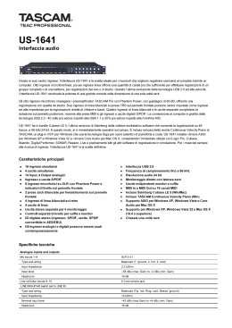
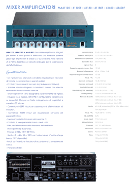
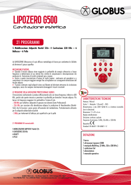
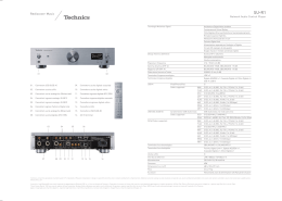
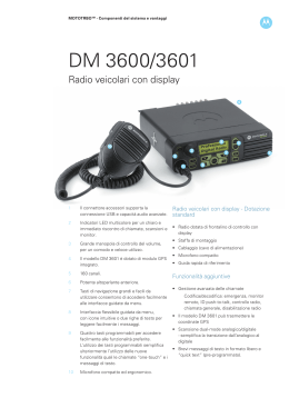
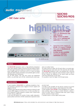
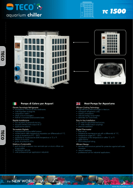
MANUALE ISTRUZIONI
OPERATING MANUAL
Delivering the True Audio Experience
Delivering the True Audio Experiences
NORME DI SICUREZZA / SAFETY REGULATIONS
Onde evitare rischi per la propria e per l’altrui sicurezza,
nonché l’invalidazione della garanzia, si raccomanda di
leggere, nella sezione qui esposta, i consigli per un buon
utilizzo del prodotto.
· Non esporre l’apparecchio alla pioggia o ad elevata umidità.
· Proteggere l’apparecchio dalla penetrazione accidentale di
liquidi o di oggetti solidi; se questo dovesse avvenire, non
utilizzare più l’apparecchio e rivolgersi quanto prima ad
OUTLINE o a personale competente.
· Collegare l'apparecchio verificando SEMPRE il contatto di
messa a terra come richiesto dalle normative.
· Se il cavo di collegamento originale presentasse segni di
usura o di deterioramento, sostituirlo con uno analogo.
· Eseguire i collegamenti in modo ordinato limitarne l'accesso
o l'avvicinamento solo al personale addetto.
· La movimentazione dell’apparecchio deve avvenire solo a
cavi scollegati.
· L’apparecchio non deve essere aperto e/o riparato se non
da personale competente.
· Per qualsiasi esigenza o informazione di natura tecnica
rivolgersi ad OUTLINE o a personale autorizzato.
In order to avoid risks for the user's and other people's
safety, as well as annulling the warranty, it is advisable to
read the suggestions in this section for correct use of the
product.
· Do not expose the unit to rain and don’t use it in locations
with a high humidity level.
· Ensure that no liquids or solid objects accidentally enter the
unit; should this occur, stop using the unit and contact
OUTLINE or specialist staff.
· When connecting the unit, ALWAYS check ground connection
as required by technical and safety norms.
· If the original cable is worn or damaged, it must be replaced
with another of the same type (in perfect condition).
· Carry out connections in an orderly fashion, only allowing
access to this procedure to expert staff.
· The unit must only be moved when the cables are
disconnected.
· The unit must only be opened and/or repaired by specialist
staff.
· For any requirements of a technical nature, contact
OUTLINE or authorized staff.
SMALTIMENTO RIFIUTI / DISPOSAL OF WASTE MATERIALS
L'apparecchio è stato progettato e prodotto con
materiali e componenti di qualità elevata riciclabili e
riutilizzabili. Il simbolo del cassonetto su ruote barrato
indica che l'apparecchio è conforme alla Direttiva
Europea 2002/96/CE e successiva modifica
2003/108/CE. Informarsi sui regolamenti locali in merito alla
raccolta differenziata di prodotti elettronici ed elettrici.
Attenersi ai regolamenti locali ed evitare di smaltire i vecchi
apparecchi come normali rifiuti domestici. Si ricorda che un
corretto smaltimento dell'apparecchio aiuta a salvaguardare la
salute e l'ambiente.
COMFORMITÀ
*Comunità Europea
*
Tutte le apparecchiature elettroniche ed elettroacustiche
Outline rispondono ai requisiti indicati dalle direttive CEE.
La dichiarazione di conformità CE è allegata alla garanzia.
2
Your product is designed and manufactured with highly
quality material and components, which can be recycled
and reused. When this crossed-out wheeled bin symbol is
attached to a product, it means the product is covered by
the European Directive 2002/96/EC and subsequent
amendment 2003/108/EC. Please inform yourself about the local
separate collection system for electrical and electronic products.
Please act according to your local rules and do not dispose your
old products with your normal household waste. The correct
disposal of your old product will help prevent potential negative
consequences for the environment and human health.
* COMFORMITY
*European Community
All the Outline electroacoustic and electronic devices are in
accordance with the objects stated by below CEE directives:
The CE declaration of conformity is attached to the product
warranty.
Outline s.r.l. - Via Leonardo da Vinci, 56 - 25020 Flero (Brescia) - Italy
Tel. +39-30-3581341 Fax +39-30-3580431 — Web Site: www.outline.it E-Mail: [email protected]
iMode Digital Loudspeaker Processor
iP24
Grazie per aver scelto Outline iP24 per le vostre applicazioni di
gestione di sistemi audio. Vi suggeriamo di leggere con
attenzione questo manuale così da poter sfruttare al meglio le
molte possibilità dell'apparecchiatura.
Thank you for choosing Outline iP24 for the management of
your loudspeaker system. We suggest that you read carefully
this manual in order to fully exploit all the possibilities of this
device.
Outline iP24 utilizza la tecnologia iMode, che consente di
controllare sistemi di amplificazione con estrema semplicità,
flessibilità e affidabilità.
Outline iP24 employs the Outline’s proprietary iMode
technology, that allows to control any amplification system
with extreme simplicity, flexibility and reliability.
Outline iP24 è dotato di doppio compressore-limiter per ogni
canale di uscita, ritardi, filtri, polarità e qualsiasi altra
funzione che ci si possa aspettare da un controller DSP, ma si
distingue per l’utilizzo della tecnologia estremamente
avanzata WFIR (Warped-frequency FIR), una tecnica di sintesi
delle equalizzazioni che permette di riprodurre risposte in
frequenza complesse senza aggiungere latenza.
La tecnologia WFIR è caratterizzata da una distribuzione della
risoluzione costante per ottave, a differenza della tecnologia
FIR, per la quale la risoluzione è molto buona per le ottave più
alte e, a volte, non sufficiente per le ottave più basse. In questi
casi, per ottenere buone risoluzioni in bassa frequenza, si
impiegano FIR multi-banda, che dividono il segnale in più bande
sotto-campionate al costo di una latenza maggiore. La
tecnologia WFIR, al contrario, permette di ottenere risposte in
frequenza anche molto complesse senza aggiungere latenza,
proprio perché la distribuzione della risoluzione in frequenza è
logaritmica, ovvero è molto simile alla risoluzione percepita
dall’orecchio umano.
Per maggiori informazioni riguardo la tecnologia iMode, ti
invitiamo a visitare il sito www.outlineimode.com.
Outline iP24 features a double stage compressor-limiter on
each output, delays, filters, polarity and any other function
available on standard DSP, but it features also an extremely
advanced technology called WFIR (Warped-frequency FIR). This
is a technique of equalization synthesis that is able to
reproduce articulated frequency responses without adding any
latency.
The WFIR technology features a constant resolution per octave,
that is different from the FIR technology, in which the
resolution is very good for higher octaves, while, many times, is
poor for lower frequencies. In this cases, in order to obtain a
good resolution at low frequencies, multi-band FIR are used.
These filters divide the signal in multiple bands that are undersampled. The result of this process is also an increased latency.
The WFIR technology, on the contrary, is able to create very
complex frequency responses without adding latency, because
the frequency resolution is logarithmically distributed and is
also very similar to the frequency resolution perceived by the
human ears.
More details about the iMode technology are available on the
website www.outlineimode.com.
Outline iP24 è dotato di due ingressi e quattro uscite che
possono essere utilizzate sia in modo analogico che digitale
(AES/EBU).
L’apparecchio può anche essere utilizzato come generatore di
segnale, in grado di riprodurre rumore bianco, rumore rosa e
sinusoide (100 Hz - 1 kHz - 10 kHz).
Outline iP24 features two input channels and four output
channels both analog or digital (AES/EBU).
The device can be used also as a signal generator, the available
signals are pink noise, white noise and sine wave (100 Hz - 1 kHz
- 10 kHz).
Outline iP24 è inoltre dotato di due ingressi e uscite generiche
supplementari configurabili (General Purpose Input Output),
disponibili su connettore DB9, che consentono l’integrazione
con sistemi esterni come allarmi antincendio, controlli di
potenza, sistemi di muting, sistemi di monitoraggio, ecc...
Outline iP24 is also fitted with a generic configurable 2-in 2-out
supplementary port (General Purpose Input Output) on a DB9
connector, allowing the integration of the device in external
systems, like fire alarm, power controls, muting systems,
monitoring systems, etc...
La scelta di poter costantemente migliorare e implementare le
funzioni dell’apparecchio, ha spinto Outline ad una scelta
minimalista per quanto concerne l’interfaccia hardware.
Outline iP24 è infatti completamente controllabile da remoto
mediante utilizzo di un protocollo Ethernet standard: tramite
web browser (che supporti la tecnologia Java) da computer o
tramite dispositivi Apple® (iOS e OSX).
The need of constantly monitoring and controlling each
parameter of the device, drove Outline to choose a
minimalistic hardware interface. Outline iP24 is therefore
completely remotely controllable via Ethernet standard
communication: via web browser (supporting Java
applications) from a computer or via Apple® devices (iOS and
OSX).
Outline s.r.l. - Via Leonardo da Vinci, 56 - 25020 Flero (Brescia) - Italy
Tel. +39-30-3581341 Fax +39-30-3580431 — Web Site: www.outline.it E-Mail: [email protected]
3
Delivering the True Audio Experiences
PANNELLO ANTERIORE / FRONT PANEL
1
2
3
4
5
1)
STATUS: LED che indica il corretto funzionamento
dell’apparecchio. All’accensione il Led diventa di colore
rosso e lo mantiene per tutta la durata della fase di check
(indicativamente una decina di secondi), terminata la
quale assume il colore definitivo:
Verde - se è attivo l’ingresso anaolgico.
Magenta - se è attivo l’ingresso digitale.
1)
STATUS: this LED indicates that the device is working
properly. During the startup this LED remains red in order
to indicate that the various checks are running (for about
ten seconds). After this phase the LED turns to a different
colour depending on the selected input type:
Green - analog input selected.
Magenta - digital input selected.
2)
HOME: pulsante da utilizzare nel caso in cui ci siano
problemi di riconoscimento dell’apparecchiatura sulla
rete. Tenendolo premuto all’accensione, viene
disabilitata la modalità DHCP e l’apparecchio viene
impostato con i seguenti parametri:
Indirizzo IP:
192.168.1.34
SUBNET MASK:
255.255.255.0
DEFAULT GATEWAY: 192.168.1.250
2)
HOME: this push-button sets the network to a temporary
configuration, that is useful for troubleshooting network
problems. By pressing this button before turning on the
device and holding it during the whole start-up phase, the
device is set with the following parameters:
IP address:
192.168.1.34
SUBNET MASK:
255.255.255.0
DEFAULT GATEWAY: 192.168.1.250
3)
IN (1-2): LED che indicano il livello dei segnali presenti in
ingresso o che l’apparecchio è nello stato di MUTE.
Verde - segnale presente (da -60 dBFS ).
Giallo - segnale al limite del clipping .
Rosso - segnale troppo elevato o canale nello stato di
mute (impostabile da remoto).
3)
IN (1-2): these LEDs indicate the level and the mute status
of the input channels.
Green - signal is present.
Yellow - signal close to the clip level.
Red - channel clipping or channel in mute (remotely
selectable)
4)
BLINK: questo LED bianco, ad alta intensità, può essere
acceso da remoto per facilitare l’individuazione
dell’apparecchio.
4)
BLINK: this white, high-power LED can be remotely
switched on in order to easily identify the device.
5)
OUTPUT (1-2-3-4): these LEDs indicate the levels and the
mute status of each output channel.
Green - signal present on the output with no limiting (if
the limiter is active) and with no clipping.
Yellow - indicates that the output level reached the
maximum level set in the limiter circuit and that the signal
started to be limited (at least 1 dB). If the limiter is not
active, it indicates that the output is close to the clipping
level.
Red - the output channel is muted (selectable from the
remote application) or the signal is heavily limited, if the
limiter is active, or, if the limiter is not active, that the
signal is above the maximum allowed level and is clipping.
5)
4
OUTPUT (1-2-3-4): LED che indicano il livello del segnale
presente in uscita e lo stato di MUTE.
Verde - segnale presente senza intervento del limiter (se
inserito) e non soggetto a clipping.
Giallo - se il limiter è inserito indica che il segnale ha
raggiunto il livello massimo impostato (da remoto) ed il
circuito di limitazione sta intervenendo di almeno 1 dB.
Se il limiter non è inserito indica che il livello del segnale è
al limite del clipping.
Rosso - se l’apparecchio è nello stato di mute (impostabile
da remoto) o se il limiter è inserito indica che il circuito di
limitazione sta intervenendo decisamente; se il limiter
non è inserito indica che il segnale è troppo elevato e sta
clippando.
Outline s.r.l. - Via Leonardo da Vinci, 56 - 25020 Flero (Brescia) - Italy
Tel. +39-30-3581341 Fax +39-30-3580431 — Web Site: www.outline.it E-Mail: [email protected]
iMode Digital Loudspeaker Processor
iP24
PANNELLO POSTERIORE / REAR PANEL
1
2
3
1)
MAINS INPUT: connettore per l’alimentazione da rete
dotato di interruttore di accensione e di portafusibile.
La circuitazione di tipo switch mode consente l’utilizzo
dell’unità con qualsiasi tensione di rete compresa tra i
90 V AC e i 260 V AC.
Verificare che il fusibile inserito nell’apposita sede sia del
valore corretto in base alla tensione di alimentazione:
115 V AC -> fusibile 1.2 AT.
230 V AC -> fusibile 630 mAT.
Per il collegamento alla rete utilizzare l’apposito cavo in
dotazione.
2)
ANALOG OUT (1-2-3-4): connettori di tipo XLR per il
collegamento bilanciato delle uscite di tipo analogico.
Pin 1: schermo (SHIELD).
Pin 2: segnale in fase (HOT).
Pin 3: segnale in controfase (COLD).
3)
ANALOG IN (1-2): connettori di tipo XLR per il
collegamento bilanciato degli ingressi di tipo analogico.
Pin 1: schermo (SHIELD).
Pin 2: segnale in fase (HOT).
Pin 3: segnale in controfase (COLD).
4)
ETHERNET: connettori RJ45 per il collegamento di rete.
PORT 1: per la connessione con il computer o con un access
point.
PORT 2: per la connessione a PORT 1 di altre
apparecchiature equipaggiate con tecnologia iMode.
5)
4
5
6
7
8
1)
MAINS INPUT: main power supply socket with power
button and fuseholder.
The switch-mode power supply enables the system to be
used from 90 V AC to 260 V AC.
Check that the fuse value is correct. The fuse is different
depending on the actual mains power level
115 V AC -> 1.2 AT fuse.
230 V AC -> 630 mAT fuse.
Please use the supplied power chord in order to connect
the device to the mains power.
2)
ANALOG OUT (1-2-3-4): XLR balanced analog output
connectors
Pin 1: SHIELD.
Pin 2: HOT.
Pin 3: COLD.
3)
ANALOG IN (1-2-3-4): XLR balanced analog input
connectors
Pin 1: SHIELD.
Pin 2: HOT.
Pin 3: COLD.
4)
ETHERNET: RJ45 connectors for the communication in an
Ethernet network
PORT 1: connection to the computer or router or access
point
PORT 2: connection to PORT 1 of an other iP 24 or iModeequipped device.
AES/EBU OUT (1/2 - 3/4): connettori di tipo XLR per il
collegamento delle uscite digitali secondo il protocollo
AES/EBU.
5)
AES/EBU OUT (1/2 - 3/4): XLR digital output connectors
(AES/EBU protocol).
6)
AES/EBU IN (1/2): connettori di tipo XLR per il
collegamento degli ingressi digitali secondo il protocollo
AES/EBU.
6)
AES/EBU IN (1/2): XLR digital input connector (AES/EBU
protocol).
7)
I/O PORT: connettore di tipo DB9 per utilizzo tipo generico
programmabile da remoto.
7)
I/O PORT: General Purpose Input Output on a DB9
connector, remotely programmable.
8)
RS 485: connettore RJ45 per la comunicazione seriale
(RS 485) con altre apparecchiature (ad esempio
amplificatori Outline serie T). Funzione non ancora
disponibile.
8)
RS 485: RJ45 connector intended to be used for serial
communication (RS 485) with other devices, like Outline
T-series amplifiers. This function will be soon
implemented.
Outline s.r.l. - Via Leonardo da Vinci, 56 - 25020 Flero (Brescia) - Italy
Tel. +39-30-3581341 Fax +39-30-3580431 — Web Site: www.outline.it E-Mail: [email protected]
5
Delivering the True Audio Experiences
DISIMBALLAGGIO / UNPACKING
Dopo il disinballaggio si prega di verificare con la massima
attenzione la presenza di eventuali danni. In caso affermativo
si prega di avvisare il rivenditore.
After unpacking the unit, check very carefully for any damage.
If any damage is found, please notify your dealer.
Si consiglia di conservare l’imballo da utilizzare in caso di
trasporto dell’unità in un secondo momento.
It is advisable to keep the packaging for use in the event of the
unit being transported in the future.
L’unità Outline iP24 viene fornita con i seguenti accessori:
¶ N°1 cavo di alimentazione
¶ Certificato di garanzia
¶ Questo manuale
The Outline iP24 is supplied with the following accessories:
¶ N°1 power cable
¶ Warranty certificate
¶ Operating manual
DIMENSIONI MECCANICHE / MOUNTING DIMENSIONS
44
482
435
5
A
6
B
Outline s.r.l. - Via Leonardo da Vinci, 56 - 25020 Flero (Brescia) - Italy
Tel. +39-30-3581341 Fax +39-30-3580431 — Web Site: www.outline.it E-Mail: [email protected]
175
B
168,5
A
iMode Digital Loudspeaker Processor
iP24
INSTALLAZIONE / INSTALLATION
MONTAGGIO
L'apparecchio iP24 è stato progettato per il montaggio in rack
standard 19" dove occupa una unità (44.5 mm).
Una ventola permette il raffreddamento dei componenti
interni dell’apparecchio quando la temperatura interna supera
una certa soglia. È assolutamente importante mantenere libere
le bocche di ingresso e di uscita dell’aria sui lati
dell’apparecchio (viste “A” e “B” nella pagina precedente).
Se l’apparecchio è montato all’interno di una struttura
trasportabile, soggetta a forti vibrazioni, è consigliabile
provvedere ad un supporto sul retro e/o sui lati per diminuire lo
sforzo sul pannello frontale.
MOUNTING
The iP 24 has been designed for 19" standard rack mounting and
occupies one unit (44.5 mm)
An internal fan takes care of cooling the unit’s internal
components when the temperature is above a certain
threshold. It is very important to keep the ventilation ports
free. These ports are located on the two sides of the device
(views “A” and “B” from the previous page).
If the unit is mounted in a rack or other structure that is
transported, therefore subject to considerable vibration, it is
advisable to provide support at the rear and/or sides of the unit
in order to reduce the stress on the front panel.
PRECAUZIONI PER L’INSTALLAZIONE
L’installazione in luoghi eccessivamente umidi o polverosi
può causare danni o mal funzionamenti dell’apparecchio.
Come in qualsiasi dispositivo elettronico di processo del
segnale a basso livello, è meglio evitare di montare l’unità
vicino ad una forte sorgente di radiazioni magnetiche, per
esempio un amplificatore di potenza, per mantenere al minimo
il livello di rumore.
INSTALLATION PRECAUTIONS
Installation in excessively damp or dusty locations could
damage the unit or cause faulty operation.
As with any low-level signal processing electronic device, it is
recommended to avoid mounting the unit close to a source of
strong magnetic radiation (a power amplifier for example) in
order to prevent any unwanted noise issue.
COLLEGAMENTO ALLA RETE
Ciascun iP24 è equipaggiato con un cavo a tre conduttori; Il filo
giallo-verde del cavo di rete deve sempre essere connesso a
terra (ground). Ciò si richiede anche in caso di prolungamento
del cavo, adattamento a prese esistenti, riduzioni, etc.
Questo è essenziale sia per la sicurezza che per il corretto
funzionamento del sistema. All’interno dell’apparecchio il filo
giallo-verde è connesso alla carcassa di metallo. Ogni parte del
rack nel quale è montata questa apparecchiatura deve essere
connessa a terra.
MAINS POWER CONNECTION
Each iP24 is equipped with a 3-conductor cable; the green-andyellow wire of the mains cord must always be connected to
Earth or Ground. This is also necessary even in case of cable
extensions, adaptation of existing mains sockets, adaptors, etc
This is essential for safety and correct system operation. Inside
the unit, the yellow/green wire is connected to the metal
chassis. Every part of the rack in which this unit is mounted
must also be earthed.
ATTENZIONE! QUESTO APPARECCHIO DEVE ESSERE SEMPRE
CONNESSO A TERRA.
IL COSTRUTTORE DECLINA OGNI RESPONSABILITÀ DA EVENTUALI
DANNI PROVOCATI DALLA NON OSSERVANZA DI TALE NORMA.
WARNING! THIS UNIT MUST ALWAYS BE GROUNDED.
THE MANUFACTURER DECLINES ANY AND ALL RESPONSIBILITY
FOR ANY DAMAGES CAUSED BY NON-OBSERVANCE OF THIS
NORM.
TENSIONE DI ALIMENTAZIONE
Il processore iP24 utilizza un sistema di alimentazione
switching che offre alta efficienza e bassa dispersione di
calore. Esso accetta universalmente tensioni in ingresso tra
90 V AC e 250 V AC (nominali), e non richiede alcuna
regolazione.
Al di fuori di questo campo l’unità non lavora correttamente.
Tensioni troppo elevate causerebbero dei danni; tensioni
troppo basse porterebbero allo spegnimento del sistema.
POWER REQUIREMENTS
The iP24 uses a switching power system that ensures high
efficiency and low heat dispersion. It accepts any input power
voltage between 90 V AC and 240 V AC (nominal), without
requiring any adjustment.
Outside this range the unit will not work properly. If voltage
exceeds the maximum limit, it will probably cause damage and
excessively low voltage will cause the system to shut down.
COLLEGAMENTI AUDIO
Outline iP24 è dotato di due ingressi e quattro uscite. Gli
ingressi sono analogici o digitali (AES/EBU), selezionabili via
remoto, mentre le uscite sono contemporaneamente sia
analogiche che digitali (AES/EBU). Tutti gli ingressi e le uscite
analogiche sono bilanciate elettronicamente.
Il collegamento avviene tramite connettori XLR.
INGRESSI ANALOGICI
Gli ingressi hanno un’impedenza nominale di 100 kΩ.
Per i segnali non bilanciati utilizzare i pin HOT (segnale in fase)
e GND (massa) ed è consigliabile collegare a massa il pin COLD
(segnale invertito di fase) per ridurre al minimo il rumore.
AUDIO CONNECTIONS
The Outline iP24 has two inputs and four outputs. The inputs
are analog or digital (AES/EBU) which are remotely selectable,
while the outputs are simultaneously both analog and digital.
All the analog inputs and outputs are electronically balanced.
The connection is made via XLR connectors.
INPUTS
The inputs have a nominal impedance of 100 kΩ.
If unbalanced signals are present, use the HOT pin (in-phase
signal) and GND pin (ground), and it is advisable to connect the
COLD pin (inverted-phase signal) to ground to keep noise to a
minimum.
Outline s.r.l. - Via Leonardo da Vinci, 56 - 25020 Flero (Brescia) - Italy
Tel. +39-30-3581341 Fax +39-30-3580431 — Web Site: www.outline.it E-Mail: [email protected]
7
Delivering the True Audio Experiences
USCITE
Le uscite hanno un’impedenza nominale di 47 Ω.
Per i segnali non bilanciati utilizzare i pin HOT (segnale in fase)
e GND (massa).
OUTPUTS
The outputs have a nominal impedance of 47 Ω.
For unbalanced signals, use the HOT pin (in-phase signal) and
GND pin (ground).
Consigli per i collegamenti
· Usare solo cavi schermati di alta qualità.
· I collegamenti non bilanciati devono essere il più corti
possibile (non superare i 3/4 metri).
· Non posizionare cavi di segnale a basso livello vicino ad
altri con segnali ad alto livello (cavi altoparlanti) e a cavi
di alimentazione. Questo evita l'introduzione di disturbi
per induzione.
· Disalimentare l’apparecchio prima di eseguire
cambiamenti nei collegamenti.
Advice for connections
· Use only good quality screened cables.
· Unbalanced connections must be as short as possible (no
more than 3 or 4 metres).
· Do not position low-power signal cables near other cables
carrying high-power signals (loudspeaker cables) or mains
supply cables. This will avoid interference due to
induction.
· Disconnect the unit from the mains power supply before
making any changes to the connections.
ACCENSIONE
Connettere l’unità iP24 alla rete elettrica con il cavo in
dotazione e accendere l’unità tramite l’apposito pulsante.
L’unità si accenderà, il LED dello STATUS sarà di colore rosso per
tutto il tempo di avvio, durante il quale verrà eseguito un check
dei LED. Al termine di questa fase il LED dello status diventerà
verde o magenta a seconda del tipo di input selezionato. A
questo punto l’unità è in funzione.
SWITCHING ON
Connect the iP24 to the mains power with the cable provided
and switch on the unit with the dedicated power button.
The unit will automatically turn on, the STATUS LED will be red
during the start-up phase, during this phase the unit will run
also a LED check. After this phase the STATUS LED will turn
green or magenta depending on the input selected and the unit
will be ready to be used.
CARATTERISTICHE / FEATURES
m
m
m
m
m
m
m
m
m
m
m
m
8
Ingressi ed uscite analogiche e digitali
Due porte Ethernet
Monitoraggio in tempo reale e controllo remoto
Porta RS485 per comunicazione seriale con altri dispositivi
Possibilità di controllo e di comando di e da dispositivi
esterni tramite porta generica I/O
Due canali di ingresso completamente configurabili
Tecnologia WFIR per le equalizzazioni (fino a 32
equalizzatori distribuiti su quattro livelli per ciascun
ingresso)
Possibilità di assegnare ciascun canale di ingresso a tre
gruppi contemporaneamente
Controlli di input e di gruppo: livelli, ritardi, polarità ed
equalizzazioni (32 filtri distribuiti su quattro layer)
Doppio stadio compressore-limiter su ogni uscita
16 equalizzatori IIR su ciascuna uscita
Crossover con pendenze di 6, 12, 18, o 24 dB per ottava,
filtri tipo Butteworth o Linkwitz-Riley
m
m
m
m
m
m
m
m
m
m
m
m
Analog and digital inputs and outputs
Two Ethernet ports
Real-time remote monitoring and control
RS485 port for serial communication with other devices
Possibility to control other devices or to be controlled by
other devices via the generic I/O port
Two completely configurable input channels
Input equalization implemented with the WFIR technology
(up to 32 filters distributed over four layers for each input
channel)
Each input can be assigned to three group at the same
time
Available input and group controls: level, delay, polarity,
equalizations (32 filters distributed over four layers)
Double stage compressor-limiter on each output
16 IIR filters on each output
Selectable output crossover: 6, 12, 18 or 24 dB/octave
Butterworth or Linkwitz-Riley
Outline s.r.l. - Via Leonardo da Vinci, 56 - 25020 Flero (Brescia) - Italy
Tel. +39-30-3581341 Fax +39-30-3580431 — Web Site: www.outline.it E-Mail: [email protected]
iMode Digital Loudspeaker Processor
iP24
COMUNICAZIONE CON IL DISPOSITIVO / COMMUNICATION WITH THE DEVICE
COLLEGAMENTO CON IL COMPUTER O iPAD®/iPHONE®
Il collegamento con il computer deve essere effettuato
mediante la rete ethernet, utilizzando cavi di rete CAT 5.
Il collegamento ad un iPad®, iPhone® o computer con wifi
avviene tramite la costruzione di una rete wireless. Sarà quindi
indispensabile utilizzare un router wireless (non fornito), che
sia in grado di funzionare anche come DHCP server (vedi il
paragrafo “Configurazione della rete”).
Il cavo proveniente dal computer o dall’access point deve
essere collegato al connettore ethernet chiamato “PORT 1”
dell’iP24. I successivi iP24 possono essere collegati
direttamente all’access point (utilizzando una delle porte LAN
disponibili) oppure in successione al primo iP24. In questo caso
collegare un cavo dal connettore “PORT 2” del primo iP24 al
connettore “PORT 1” del successivo.
COMPUTER, iPAD® AND iPHONE® CONNECTION
The connection to the computer must be made through an
ethernet network, using standard CAT 5 network cables.
The connection to the iPad®, iPhone® or computer with wifi
requires the construction of a wireless network. Therefore it
will be necessary to use a wireless router (not included), that
can also work as a DHCP server (see the “Network setup”
paragraph for more information).
The ethernet cable from the computer or the access point has
to be plugged into the connector called “PORT 1” of the iP24.
The other iP24 can be connected directly to the access point
(using an other available LAN port) or can be daisy chained from
the first iP24. In this case a network cable has to be plugged
from “PORT 2” of the first device to the “PORT 1” of the next
iP24.
SOFTWARE
Nel caso di utilizzo con personal computer non è necessario
installare alcun software. E’ sufficiente utilizzare un comune
web browser che supporti le applicazioni Java®. Per
comunicare con un singolo iP24 aprire il web browser e digitare
l’inidirizzo IP del dispositivo nella barra degli indirizzi.
Comparirà automaticamente l’applicazione Java, tramite la
quale è possibile controllare tutti i parametri inerenti alla
singola macchina, ma non ai gruppi.
Sull’Apple Store è disponibile l’applicazione “iP24" per iPad®.
Questa consente il monitoraggio, il controllo contemporaneo e
la gestione a gruppi di più iP24. È possibile memorizzare e
condividere, tramite e-mail, i parametri di più macchine, così
come realizzare progetti off-line.
SOFTWARE
In case of use with a personal computer, no special software is
required, but just a web browser that supports Java®
applications. In order to communicate with a single iP24, start
the web browser and write the device’s IP address in the
address bar. The Java application will start automatically.
Using this application it will be possible to control all the
parameters of the single device, but not the groups.
The application called “iP24” for iPad® is available on the App
Store. Through this application is possible to monitor and
control each single device and groups of iP24. It is possible to
save and share, via e-mail, all the parameters of all the devices
in the project, as well as to work in offline mode.
CONFIGURAZIONE DELLA RETE
I processori iP24 utilizzano un protocollo di rete di tipo TCP e
UDP, conforme allo standard RFC 768.
Tutti i dispositivi (processori, computer, iPad® e router)
connessi in una rete locale comunicano tramite indirizzi IP.
Perchè tutto funzioni é necessario che:
Ÿ a ciascun dispositivo sia assegnato un indirizzo IP;
Ÿ non esistano indirizzi IP duplicati;
Ÿ tutti gli indirizzi IP appartengano alla stessa sottorete.
Ad esempio, se il dispositivo ha le seguenti impostazioni di
rete:
Indirizzo IP:
192.168.1.34
SUBNET MASK: 255.255.255.0
Per far sì che ci sia comunicazione con il computer, l’iPad® o il
router, è necessario che quest’ultimo abbia un indirizzo IP
diverso, ma che appartenga alla stessa sottorete. In base
all’esempio proposto una possibile configurazione di rete per il
computer é la seguente:
Indirizzo IP:
192.168.1.10
SUBNET MASK: 255.255.255.0
NETWORK SETUP
Outline iP24 uses the TCP and UDP, according to standard RFC
768.
All the devices (processors, computer, iPad® and router)
connected to the same local network communicate via IP
addresses. The basic rules of this addressing mode are
presented here:
Ÿ each device must have an assigned IP address;
Ÿ the IP addresses must be unique (no duplicates);
Ÿ all the IP addresses have to belong to the same subnet.
I.e if the loudspeaker has the following network settings:
IP address:
192.168.1.34
SUBNET MASK: 255.255.255.0
In order to have the communication with the computer, the
iPad® or the router, the latter must have a different IP address
belonging to the same subnet. In this case, one possible
network address for computer is:
IP address:
192.168.1.10
SUBNET MASK: 255.255.255.0
Questi indirizzi IP possono essere assegnati manualmente o
automaticamente (DHCP). I processori iP24 vengono forniti, di
fabbrica, con l'opzione DHCP abilitata.
DHCP significa "Dynamic Host Configuration Protocol". Con
questa opzione abilitata i dispositivi attendono l'assegnazione
di un indirizzo IP valido da un server DHCP (di solito
implementato in ogni router wireless) per circa un minuto. È
consigliato accendere il router prima di ogni dispositivo.
The IP addresses can be assigned manually or automatically
(DHCP).The iP24 are supplied, as standard, with the DHCP
option enabled.
DHCP means "Dynamic Host Configuration Protocol". If this
option is enabled, the devices are waiting for a valid IP address
from a DHCP server (usually implemented in any wireless
router) for about one minute. It is strongly suggested to switch
on the router before any device.
Outline s.r.l. - Via Leonardo da Vinci, 56 - 25020 Flero (Brescia) - Italy
Tel. +39-30-3581341 Fax +39-30-3580431 — Web Site: www.outline.it E-Mail: [email protected]
9
Delivering the True Audio Experiences
RISOLUZIONE PROBLEMI
Nel caso in cui non si disponga di un DHCP server o non si
conosca l’indirizzo IP assegnato manualmente all’unità iP24 è
possibile ripristinare l’indirizzo di default (192.168.1.34)
accendendo il sistema tenendo premuto il tasto “Home”.
L’indirizzo così ripristinato rimane attivo solo fino allo
spegnimento dell’apparecchio, ma può essere modificato da
software.
In questo caso è possibile comunicare con il processore,
connettendolo direttamente al computer con un normale cavo
di rete CAT5. Il computer deve avere un indirizzo IP manuale
che rispetti le regole descritte al paragrafo “Configurazione
della rete” (ad esempio: 192.168.1.10).
TROUBLESHOOTING
If the DHCP is not available or if you do not know the IP address
manually assigned to the iP24 unit, you can restore the default
address (192.168.1.34) by switching on the system holding
down the “Home” button. The restored default address is
active only up to the shutdown of the system, but can be
modified by software.
In this case it is possible to communicate with the device,
connecting it directly to a computer via a CAT5 network cable.
The computer must have a manual IP address that respects the
rules described in the “Network Setup” paragraph (i.e.
192.168.1.10).
INDICAZIONI PER LA RETE WIRELESS
Il router wireless deve avere le seguenti caratterisitche:
Ÿ almeno una porta LAN per la connessione con gli iP24;
Ÿ DHCP server abilitato;
Ÿ rete wireless abilitata (per la comunicazione con iPad®,
iPhone® e computer wireless).
Si consiglia, dal primo uso, di cambiare la password di
amministratore del router, modificare il nome della rete
wireless e selezionare una password di accesso (WPA2). Queste
informazioni dovranno essere salvate, in quanto saranno utili
per l’accesso alla rete e per impostare il router. Il computer e
l’iPad® che saranno utilizzati per il controllo devono rispettare
le regole di comunicazione di rete, quindi si consiglia di
impostarli in modalità DHCP (ottieni automaticamente
indirizzo IP).
Le capacità di controllo tramite dispositivi senza cavo
dipendono drasticamente da numerosi fattori, quali il
posizionamento dell’antenna e l’interferenza con altre reti
wireless. Nello specifico si consiglia di:
Ÿ posizionare l’access point in modo tale che l’antenna sia
visibile e lontana da ostacoli;
Ÿ se sono attive altri network (come in fiere, grandi strutture
o luoghi affollati) usare reti wireless a 5 GHz (non
supportato da iPhone®).
Per avere un controllo migliore sulle prestazioni della rete
senza fili, molti analizzatori wifi per computer, tablet e
telefoni sono disponibili sul web.
WIRELESS ROUTER BASIC SETTINGS
The minimum wireless router set-up requires:
Ÿ at least one LAN port for connection to the iMode device;
Ÿ DHCP server enabled;
Ÿ wireless Network enabled (for the communication with
iPad®, iPhone® and wireless computers).
It is strongly suggested, from the first use, to change the router
administrator password and to modify the wireless name and
choose a security password (WPA2). Please store these data,
they will be useful in the future both to access to the net and to
set it up. The Computer and the iPad® running the control
application have to respect the network communication rules,
so it is suggested to set them as DHCP (Automatic IP) mode.
The ability to control via wireless device dramatically depends
on many factors, such as the position of the wireless antenna
and interferences with other wireless networks. Specifically,
we recommend to:
Ÿ place the access point so that the antenna is visible and
away from obstacles;
Ÿ if many networks are active in the same place (typical case
in trade fairs, large structures or crowded places) use a
5 GHz wireless (not supported by iPhone®)
To have a deeper control over the wireless performance, many
wifi analyzer for computers, tablets and phones are available
on the web.
10
Outline s.r.l. - Via Leonardo da Vinci, 56 - 25020 Flero (Brescia) - Italy
Tel. +39-30-3581341 Fax +39-30-3580431 — Web Site: www.outline.it E-Mail: [email protected]
iMode Digital Loudspeaker Processor
iP24
SPECIFICHE TECNICHE / TECHNICAL SPECIFICATIONS
SEZIONE ANALOGICA
ANALOG SECTION
Numero di ingressi analogici
Due ingressi analogici bilanciati elettronicamente
Number of analog inputs
Two analog electronically balanced inputs
Impedenza di ingresso analogica (bilanciato)
100 kΩ
Balanced analog input impedance
100 kΩ
Numero di uscite analogiche
Quattro uscite analogiche bilanciate elettronicamente
Number of analog outputs
Four analog electronically balanced inputs
Impedenza di uscita analogica (bilanciato)
47 Ω
Balanced analog output impedance
47 Ω
Risoluzione di conversione
24 bit (sigma-delta)
Conversion Resolution
24 bit (sigma-delta)
THD+N ingressi analogici
0.0016% at 1 kHz
THD+N Analog Inputs
0.0016% at 1 kHz
THD+N uscite analogiche
0.0009% at 1 kHz
THD+N Analog Outputs
0.0009% at 1 kHz
THD+N da ingresso analogico a uscita analogica
0.0017% at 1 kHz
THD+N Analog In to Analog out
0.0017% at 1 kHz
Massimo livello di ingresso analogico
+20.2 dBu @ 1% THD
Max Analog Input Level
+20.2 dBu @ 1% THD
Sensibilità nominale d’ingresso
+20 dBu, +10 dBu remotely selectable
Nominal Input Sensitivity
+20 dBu, +10 dBu remotely selectable
Rumore d’ingresso equivalente
-92.2 dBu Unweighted 10 Hz 22 kHz
Equivalent Noise Input Level
-92.2 dBu Unweighted 10 Hz 22 kHz
Massimo livello di uscita analogica
+20 dBu @ 0 dBFS
Max Analog Output Level
+20 dBu @ 0 dBFS
Livello di rumore di uscita
-95.5dBu Unweighted 10 Hz ÷ 22 kHz
Noise Output Level
-95.5dBu Unweighted 10 Hz ÷ 22 kHz
Rapporto segnale/rumore ingressi
112 dB Unweighted 10 Hz ÷ 22 kHz
114 dB A-weighted 10 Hz ÷ 22 kHz
Signal To Noise Ratio, Inputs
112 dB Unweighted 10 Hz ÷ 22 kHz
114 dB A-weighted 10 Hz ÷ 22 kHz
Rapporto segnale/rumore uscite
115 dB Unweighted 10 Hz ÷ 22 kHz
118 dB A-weighted 10 Hz ÷ 22 kHz
Signal To Noise Ratio, Outputs
115 dB Unweighted 10 Hz ÷ 22 kHz
118 dB A-weighted 10 Hz ÷ 22 kHz
Rapporto segnale/rumore
110 dB Unweighted 10 Hz ÷ 22 kHz
112 dB A-weighted 10 Hz ÷ 22 kHz
Signal To Noise Ratio
110 dB Unweighted 10 Hz ÷ 22 kHz
112 dB A-weighted 10 Hz ÷ 22 kHz
Diafonia ingressi
-108 dB 20 Hz ÷ 20 kHz @ MaxInputLevel
Crosstalk Inputs
-108 dB 20 Hz ÷ 20 kHz @ MaxInputLevel
Diafonia uscite
-93 dB 20 Hz ÷ 20 kHz @ MaxInputLevel
Crosstalk Outputs
-93 dB 20 Hz ÷ 20 kHz @ MaxInputLevel
Diafonia
-93 dB 20 Hz ÷ 20 kHz @ MaxInputLevel
Crosstalk
-93 dB 20 Hz ÷ 20 kHz @ MaxInputLevel
Outline s.r.l. - Via Leonardo da Vinci, 56 - 25020 Flero (Brescia) - Italy
Tel. +39-30-3581341 Fax +39-30-3580431 — Web Site: www.outline.it E-Mail: [email protected]
11
Delivering the True Audio Experiences
SEZIONE DIGITALE
DIGITAL SECTION
Numero di ingressi digitali
Due ingressi digitali AES/EBU (un connettore, due canali)
Number of digital inputs
Two digital AES/EBU inputs (one connector, two channels)
Number of digital outputs
Quattro uscite digitali AES/EBU (due connettori, quattro canali)
Number of digital outputs
Four digital AES/EBU outputs (two connector, four channels)
Frequenze di campionamento supportate in ingresso
44.1 kHz, 48 kHz, 96 kHz, 192 kHz
Supported Input sample rates
44.1 kHz, 48 kHz, 96 kHz, 192 kHz
THD+N
-140 dB @ 96 kHz, -139 dB @ 44.1 kHz sample rate
THD+N
-140 dB @ 96 kHz, -139 dB @ 44.1 kHz sample rate
Range dinamico
142 dB @1 kHz 96 kHz sample rate
Dynamic Range
142 dB @1 kHz 96 kHz sample rate
Tipo
Type
Transformer-isolated
Disaccoppiamento tramite trasformatore
PRESTAZIONI AUDIO
AUDIO PERFORMANCE
Frequenza di campionamento interna
96 kHz
Internal sample rate
96 kHz
Risoluzione di processamento interno
32-bit
Internal data path
32-bit
Risposta in frequenza
20 Hz ÷ 20 kHz (± 0.5 dB)
Frequency Response
20 Hz ÷ 20 kHz (± 0.5 dB)
Latenza
da ingresso AES/EBU 96 kHz a uscita AES/EBU 96 kHz: 2.6 ms
da ingresso AES/EBU 48 kHz a uscita AES/EBU 96 kHz: 3.6 ms
da ingresso AES/EBU 192 kHz a uscita AES/EBU 96 kHz: 2.0 ms
da ingresso AES/EBU 44.1 kHz a uscita AES/EBU 96 kHz: 3.8 ms
da ingresso AES/EBU 96 kHz a uscita analogica: 3.0 ms
da ingresso analogico a uscita AES/EBU 96 kHz: 1.6 ms
da ingresso analogico a uscita analogica: 2.0 ms
Latency
AES/EBU Input 96 kHz to AES/EBU Output 96 kHz: 2.6 ms
AES/EBU Input 48 kHz to AES/EBU Output 96 kHz: 3.6 ms
AES/EBU Input 192 kHz to AES/EBU Output 96 kHz: 2.0 ms
AES/EBU Input 44.1 kHz to AES/EBU Output 96 kHz: 3.8 ms
AES/EBU Input 96 kHz to Analog Output: 3.0 ms
Analog Input to AES/EBU Output 96 kHz: 1.6 ms
Analog Input to Analog Output: 2.0 ms
CONNESSIONI
CONNECTIONS
Connessione ingressi e uscite analogiche
connettori XLR 3 poli
Analog input and output connectors
3 pin XLR connectors
Connessione ingressi e uscite digitali
connettori XLR 3 poli
Digital input and output connectors
3 pin XLR connectors
Connessione ETHERNET
due connetori RJ-45
ETHERNET connector
2 x RJ-45 connector
Connessione porta seriale
un connettore RJ-45 connector (protocollo RS 485)
Serial port connector
1 x RJ-45 connector (RS 485 protocol)
Connessione multifunzione (I/O port)
un connettore DB9 con due ingressi e due uscite a contatti
puliti.
General Purpose connector
1 x DB9 connectorwith two inputs and two free contact
outputs.
Connessione alimentazione
Connettore IEC 3 poli
Power supply connector
3 pin IEC connector
12
Outline s.r.l. - Via Leonardo da Vinci, 56 - 25020 Flero (Brescia) - Italy
Tel. +39-30-3581341 Fax +39-30-3580431 — Web Site: www.outline.it E-Mail: [email protected]
iMode Digital Loudspeaker Processor
iP24
SEGNALAZIONI
INDICATORS
Ingresso analogico (@ +20 dBu di sensibilità)
Verde: -46 dBu … 11 dBu
Giallo: 11 dBu … 20 dBu
Rosso: > 20 dBu (clip)
Analog Input (@ +20 dBu sensitivity)
Green: -46 dBu … 11 dBu
Yellow: 11 dBu … 20 dBu
Red: > 20 dBu (clip)
Uscita analogica (limiter escluso)
Verde: -46 dBu … 11 dBu
Giallo: 11 dBu … 20 dBu
Rosso: > 20dBu (clip)
Analog Output (limiter bypass)
Green: -46 dBu … 11 dBu
Yellow: 11 dBu … 20 dBu
Red: > 20dBu (clip)
Uscita analogica (soglia limiter @ +10 dBu)
Verde: -46 dBu … 8 dBu (Th -2 dB)
Giallo: 8 dBu … 18 dBu (Th +8 dB)
Rosso: > 18 dBu (Th +8 dB) o clip
Analog Output (limiter threshold @ +10 dBu)
Green: -46 dBu … 8 dBu (Th -2 dB)
Yellow: 8 dBu … 18 dBu (Th +8 dB)
Red: > 18 dBu (Th +8 dB) or clip
Ingresso digitale
Verde: -66 dBFS … -9 dBFS
Giallo: -9 dBFS … 0 dBFS
Rosso: > 0 dBFS (clip)
Digital Input
Green: -66 dBFS … -9 dBFS
Yellow: -9 dBFS … 0 dBFS
Red: > 0 dBFS (clip)
Uscita digitale(limiter escluso)
Verde: -66 dBFS … -9 dBFS
Giallo: -9 dBFS … 0 dBFS
Rosso: > 0 dBFS (clip)
Digital Output (limiter bypass)
Green: -66 dBFS … -9 dBFS
Yellow: -9 dBFS … 0 dBFS
Red: > 0 dBFS (clip)
Uscita digitale(soglia limiter @ +10 dBu (-10dBFS))
Verde: -66 dBFS … -12 dBFS (Th -2 dB)
Giallo: -12 dBFS … -2 dBFS (Th +8 dB)
Rosso: > -2 dBFS (Th +8 dB) o clip
Digital Output (limiter threshold @ +10 dBu (-10dBFS))
Green: -66 dBFS … -12 dBFS (Th -2 dB)
Yellow: -12 dBFS … -2 dBFS (Th +8 dB)
Red: > -2 dBFS (Th +8 dB) or clip
ALIMENTAZIONE
POWER SUPPLY
Tensione di alimentazione
90/264 V AC 50/60 Hz
Power requirements
90/264 V AC 50/60 Hz
Consumo
20 W
Power consumption
20 W
FISICHE
PHISICAL
Dimensioni
1U standard EIA
Altezza:
44 mm (1.75”)
Larghezza: 483 mm (19”)
Profondità: 175 mm (6.9”)
Dimensions
1U standard EIA
Height:
44 mm (1.75”)
Width:
483 mm (19”)
Depth:
175 mm (6.9”)
Peso
Weight
2.6 Kg (net)
2.6 Kg (netto)
Outline s.r.l. - Via Leonardo da Vinci, 56 - 25020 Flero (Brescia) - Italy
Tel. +39-30-3581341 Fax +39-30-3580431 — Web Site: www.outline.it E-Mail: [email protected]
13
Delivering the True Audio Experiences
PORTA GENERICA DI INPUT-OUTPUT / GENERIC INPUT-OUTPUT PORT
I/O PORT
5 4 3
2 1
9 8 7 6
La porta generica di input/output, su connettore DB9,
consente di interfacciare il processore con un sistema esterno
di controllo (come un dispositivo di allarme anti-incendio o una
pulsantiera per il cambio di livello). Le funzioni e le risposte ad
un input sono programmabili via remoto. Queste includono:
mute singoli o collettivi degli ingressi e delle uscite,
abbassamento o innalzamento del livello di ingressi e uscite,
ecc...
Lo schema dei pin del connettore Db9 e i parametri da
rispettare sono raccolti nelle seguenti tabelle.
The generic input/output port, on a DB9 connector, gives you
the possibility to interface the processor with an external
control system (i.e. a fire alarm or an external push-button
controller to change the levels). The functions and the
response of the device to an input are remotely programmable.
The settings are including muting of all the channels or of each
single channel, lowering or raising the level of inputs and
outputs, etc...
The pin configuration of the DB9 connector and the rated limits
are reported in the following tables.
INPUT
Sono presenti due input in grado di rilevare un contatto pulito
esterno tra i pin 1 - 2 (GPI 1a - GPI 1b) e tra i pin 3 - 4 (GPI 2a GPI 2b).
INPUT
The system is able to sense an external free contact between
pin 1 - 2 (GPI 1a - GPI 1b) and between pin 3 - 4 (GPI 2a - GPI 2b).
OUTPUT
In seguito all’attivazione da parte del processore si genera la
chiusura o l’apertura di un interruttore interno tra i pin 6 - 7
(GPO 1a - GPO 1b) o tra i pin 8 - 9 (GPO 2a - GPO 2b).
Da impostazione di fabrica questi contatti sono normalmente
aperti e vengono chiusi in seguito all’attivazione del comando
da remoto. Cambiando le posizioni dei jumper interni X18 e
X20, si modifica il comportamento di questi output, che
possono essere settati individualmente per avere un contato
normalmente chiuso che viene aperto in seguito al comando da
remoto. Lo schema della posizione dei jumper interni è
stampato sulla scheda elettronica all’interno del processore.
14
OUTPUT
After the activation command given by the processor, the
internal contacts will be opened or closed between pin 6 - 7
(GPO 1a - GPO 1b) or between pin 8 - 9 (GPO 2a - GPO 2b).
By factory default the normal status of these contacts is
Normally Open and they are closed after the activation of the
remote command. It is possible to change this response by
changing the configuration of the internal jumpers X18 and
X20. Each output can be individually set in order to have a
Normally Closed contact that will be open after the remote
command. The schematics of the internal jumpers
configuration is reported on the printed circuit board inside the
iP24.
Pin
Description
GPO (Output) Relay Ratings
1
GPI 1a
Nominal Switching capacity (resistive load)
2 A 30 V DC - 0.5 A 125 V AC
2
GPI 1b / +5 V DC
Max switching power (resistive load)
60 W - 62.5 VA
3
GPI 2a
Max switching voltage
220 V DC - 125 V AC
4
GPI 2b / +5 V DC
Max switching current
2A
5
Ground
Type of selected contacts (internal)
NO or NC
6
GPO 1a
7
GPO 1b
GPI (Input) Opto-isolator Ratings
8
GPO 2a
Nominal control voltage
5 V DC
9
GPO 2b
Max control voltage
12 V DC
Outline s.r.l. - Via Leonardo da Vinci, 56 - 25020 Flero (Brescia) - Italy
Tel. +39-30-3581341 Fax +39-30-3580431 — Web Site: www.outline.it E-Mail: [email protected]
iMode Digital Loudspeaker Processor
iP24
NOTE / NOTES
Outline s.r.l. - Via Leonardo da Vinci, 56 - 25020 Flero (Brescia) - Italy
Tel. +39-30-3581341 Fax +39-30-3580431 — Web Site: www.outline.it E-Mail: [email protected]
15
Delivering the True Audio Experiences
Outline è costantemente impegnata in ricerche mirate al
continuo miglioramento dei propri prodotti. Per questo motivo,
nuove tecnologie, materiali e metodi di produzione, vengono
continuamente incorporati nei prodotti esistenti quale
espressione della nostra filosofia costruttiva. Per questa
ragione qualsiasi prodotto Outline potrà lievemente differire
dalla sua descrizione qui pubblicata, ma comunque uguaglierà
o supererà le caratteristiche qui specificate.
Outline carries out on-going research for product
improvement. New materials, manufacturing methods and
design upgrades are introduced to existing products without
prior notice as a routine result of this philosophy. For this
reason, any current Outline product may differ is some aspect
from its description, but will always equal or exceed the
original design specifications unless otherwise stated.
© Outline 2015
Manuale d’istruzioni codice: Z OMIP24V2.0
Versione: 150730
Stampato in Italia
© Outline 2015
Operating manual product code: Z OMIP24V2.0
Release: 150730
Printed in Italy
16
Outline s.r.l. - Via Leonardo da Vinci, 56 - 25020 Flero (Brescia) - Italy
Tel. +39-30-3581341 Fax +39-30-3580431 — Web Site: www.outline.it E-Mail: [email protected]
Scarica