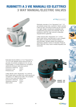
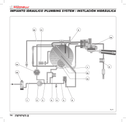
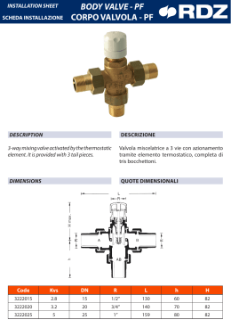
VK - BP
VK KIT VALVOLA A 3 VIE ON/OFF E PANNELLO POSTERIORE BP
VK 3-WAY ON/OFF VALVE KIT AND BP REAR PANEL
Abbinabili a ventilconvettori WH, il kit VK valvola 3 vie motorizzata ON/OFF,
posizionato nell'apposito pannello posteriore BP, interrompe il flusso dell'acqua
attraverso lo scambiatore di calore.
The VK 3-way ON/OFF motorised valve kit is suitable for WH fan coil units. It is
positioned on the BP rear panel provided, and is used to stop the water flow
through the heat exchanger.
Kit valvole WYVK
WYVK valve kit
Codice
Ventilconvettori
Code
Fan coils
WYVK10
modelli WH 10 e WH 20
WYVK10
models WH 10 and WH 20
WYVK30
modello WH 30
WYVK30
model WH 30
Kit pannello posteriore AYBP
AYBP rear panel kit
Codice
Ventilconvettori
Code
Fan coils
AYBP10
modello WH 10
AYBP10
model WH 10
AYBP20
modello WH 20
AYBP20
model WH 20
AYBP30
modello WH 30
AYBP30
model WH 30
Il kit VK si compone di:
Valvola a 3 vie / 4 attacchi con by pass incorporato, realizzata in ottone, pressione
massima di esercizio 16 bar:
Attuatore elettrotermico con le seguenti caratteristiche:
- alimentazione 230 V
- azione ON/OFF
- tempo di apertura totale 4 minuti
1 m di nastro isolante per la coibentazione del corpo valvola e dei flessibili
provenienti dagli attacchi macchina.
Tubi flessibili e guarnizioni per l'installazione della valvola alla batteria di scambio
termico.
Le perdite di carico dell valvola si ricavano dalla formula:
∆PW = (QW / KV) 2
dove
∆PW è la perdita di carico espressa in kg/cm2
QW è la portata acqua espressa in m3/h
KV è il coefficiente di portata individuabile dalla tabella
ValvolaKvs via diritta
VK kit includes:
Brass 3-way valve / 4 connections with built-in by-pass, maximum operating
pressure 16 bar;
Electrothermal ON/OFF actuator featuring:
- power supply: 230 V
- ON/OFF function
- total opening time: 4 minutes
1 m of insulating tape to insulate the valve body and hoses coming from the
machine connections.
Flexible connection pipes and gaskets for the installation of the valve on the
heat exchanger.
Pressure drops are calculated using the following formula:
∆PW = (QW / KV) 2
where
∆PW = pressure drop in kg/cm2
QW = water flow rate in m3/h
KV = water flow rate coefficient obtained from the following table
Kv by-pass
1/2 "
1,7
1,2
3/4 "
2,8
1,8
Valve
INSTALLAZIONE
Kvs right
Kv by-pass
1/2 "
1,7
1,2
3/4 "
2,8
1,8
INSTALLATION
ATTENZIONE:
IMPORTANT:
Per ogni ventilconvettore prevedere sulla rete di alimentazione un interruttore
(IL) con contatti di apertura con distanza di almeno 3mm e un fusibile (F) di
protezione adeguato.
Per l'installazione operare come segue:
1) Fissare il pannello posteriore alla parete. In figura 1 sono risportate le
dimensioni di ingombro, la corretta posizione della valvola (1) e le aperture
per il passaggio delle tubazioni (2): in caso di utilizzo di valvola i tubi dovranno
passare attraverso l'apertura di sinistra.
2) Collegare i tubi flessibili ai raccordi della macchina, prima di procedere
all'installazione della stessa.
3) Collegare la valvola alle tubazione dell'impianto rispettando le indicazioni di
figura 2 dove:
A= uscita batteria
B= ingresso acqua
C= uscita acqua
D= ingresso batteria
4) Agganciare la macchina al pannello posteriore e collegare i flessibili alla
valvola (figura 3).
5) Dopo aver controllato la tenuta idraulica procede alla coibentazione del corpo
valvola, dei tubi flessibili e delle tubazione dell'impianto.
6) Collegare lo scarico condensa.
7) Collegare elettricamente l'attuatore della valvola alla morsettiera dell'unità
come da figura (figura 4 = WH 10, figura 5 WH 20 e WH 30). I collegamenti
tratteggiati vanno eseguiti dall’installatore.
Alla pagina 3 è riportata la legenda degli schemi elettrici.
IN CASO DI UTILIZZO DI VALVOLA, IL PONTE JP1 DEVE ESSERE PRESENTE.
For each fan coil an (IL) switch should be mounted on the power supply, with
opening contacts at a distance of at least 3 mm and a suitable protection fuse
(F) .
For the installation proceed as follows:
1) Mount the rear panel on the wall. Figure 1 shows the overall dimensions,
the correct position of the valve (1) and the holes for the pipes to pass
through (2): if the valve is used, the pipes should pass through the hole on
the left side.
2) Connect the hoses to the machine connections before installing the
machine itself.
3) Connect the valve to the system pipes following the indications of figure 2
where:
A= heat exchanger outlet
B= water inlet
C= water outlet
D= heat exchanger inlet
4) Hook the machine on the rear panel and connect the hoses to the valve
(figure 3).
5) Check the tightness of the plumbing connections and proceed with the
insulation of the valve body, the hoses and the system pipes.
6) Connect the drainage hose.
7) Make the electrical connections of the valve actuator to the unit terminal
board as shown in the figure (figure 4 = WH 10, figure 5 WH 20 and WH
30). The connections indicated must be made by the installer.
The legend of the wiring diagram is shown on page 3.
WHEN THE VALVE IS USED, THE JP1 BRIDGE MUST BE PRESENT.
1
FC66001295 - rev. 00
È severamente vietata la riproduzione anche parziale di questo manuale / All copying, even partial, of this manual is strictly forbidden
VK - BP
WH 10
1
255
1
2
2
7
98
2
49,5
200
127
102
177
56,5
49,5
150
855
WH 20
100
303
1
2
2
10
2
50
300
103
102
103
50
300
56,5
1008
WH 30
100
330
1
2
2
10
2
50
300
103
102
103
300
50
56,5
1008
2
C
A
B
D
FC66001295 - rev. 00
2
È severamente vietata la riproduzione anche parziale di questo manuale / All copying, even partial, of this manual is strictly forbidden
VK - BP
3
LEGENDA SCHEMI ELETTRICI
WIRING DIAGRAM
SONDA ACQUA
FREEZE SENSOR
SENSORE T AMBIENTE
ROOM SENSOR
RAFFREDDAMENTO
COOL
RISCALDAMENTO
HEAT
AMBIENTE
ROOM
ACQUA
FREEZE
CONNETTORE RICEVITORE
CONNECTOR RECEIVER
INTERRUTTORE
SWITCH
CONNETTORE MOTORE FLAP
CONNECTOR STEPPING MOTOR
MOTORE FLAP
STEP MOTOR
ALIMENTAZIONE ELETTRICA
POWER SUPPLY
MORSETTIERA
TERMINAL BLOCK
NERO
BLACK
ROSSO
RED
GIALLO
YELLOW
BIANCO
WHITE
CONDENSATORE VENTILATORE
FAN CAP
MARRONE
BROWN
VALVOLA MOTORIZZATA
MOTORIZED VALVE
NESSUN PONTE PER APPARECCHI SENZA VALVOLA MOTORIZZATA
NO JUMPER FOR UNIT WITHOUT MOTORIZED VALVE UNIT
CON PONTE PER APPARECCHI CON VALVOLA MOTORIZZATA
WITH JUMPER FOR UNIT WITH MOTORIZED VALVE UNIT
NEUTRO
NEUTRAL
LINEA
LINE
PRESA
SOCKET
BLU
BLUE
VERDE/GIALLO
GREEN/YELLOW
MOTORE
MOTOR
ACCENSIONE/SPEGNIMENTO
ON/OFF
3
FC66001295 - rev. 00
È severamente vietata la riproduzione anche parziale di questo manuale / All copying, even partial, of this manual is strictly forbidden
VK - BP
4
5
40010 Bentivoglio (BO) - Via Romagnoli, 12/a
tel. 051/8908111 - fax 051/8908122 - www.galletti.it
FC66001295 - rev. 00
4
È severamente vietata la riproduzione anche parziale di questo manuale / All copying, even partial, of this manual is strictly forbidden
Scaricare