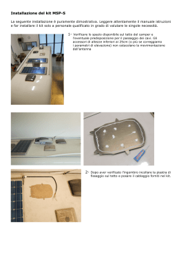
KIT ELETTROVALVOLA PER VENTILCONVETTORI A PARETE
Questa istruzione è parte integrante del libretto dell’apparecchio sul quale è stato installato l’accessorio. A tale libretto si rimanda per
le AVVERTENZE GENERALI e per le REGOLE FONDAMENTALI DI SICUREZZA.
DESCRIZIONE
Consente di deviare il flusso d’acqua dalla batteria del ventilconvettore per escluderne il funzionamento.
CONTENUTO DELLA CONFEZIONE
A
B
C
D
E
F
G
H
I
L
M
N
O
Descrizione
Kit elettrovalvola con supporto
Dima di installazione in carta
Distanziale
Coibentazione adesiva fondo ventilconvettore
Tubo scarico condensa
Isolamento per tubo scarico condensa
Tasselli ad espansione con viti
Fascetta in plastica
Viti M5 x 6,5
Staffa aggancio fondo murale
Viti 3,5 x 6,5
Staffa aggancio fondo murale
Piastra di sicurezza
Istruzioni
2-2,5kW
3,5-5kW
1
1
1
1
1
1
4
1
1
1
1
1
1
1
1
4
1
2
1
1
A
B
O
C
G
H
I
B
D
N
1
1
F
E
L
M
1
1
DATI TECNICI
Dati tecnici elettrovalvola
Temp. max di esercizio
Corsa dell’otturatore
Alimentazione
Cavetto alimentazione
Ass.
Segnale di regolazione
Temperatura ambiente di funzionamento
Spinta
Pressione massima differenziale
- Coefficiente di portata massima apertura
- Coefficiente di portata by-pass
Tempo di reazione (primo movimento a 20°C)
Classe di protezione
Elemento riscaldante
Peso
95 °C
2,5 mm
230 V
2 mt
5w
ON-OFF
0 ÷ 50°C
90 N (40 lbs)
1,6 Kvs
1 Kvs
60 sec.
IP 43
PTC
0,13 Kg
DIME D’INSTALLAZIONE
275
175
97
164,9
190
803,1
A
B
C
D
E
E
Ingombro apparecchio
Fori per viti di fissaggio
Ingombro supporto metallico
Zona collegamenti idraulici
Zona scarico condensa
D
315,6
254
289,3
80
50
93 145,5
31,6
36
35,6
50
90,9
60
15,6
279,9
263
C
80
B
A
311,9
C
152
B
106,5
A
Per modelli da 3,5 a 5 kW
182,8
41,6
Per modelli da 2 a 2,5 kW
440
97
190
264,4
261,9
887,1
E
Cod. 5773027700 v.1 (01-2006)
D
28,1
MASSIMA APERTURA
BY-PASS
DN 1/2" Kvs 1 (Dv)
[m bar]
200
DN 1/2" Kvs 1.6
2000
[kPa]
20
[m bar]
200
100
80
1000
800
2000
10
8
100
80
1000
800
10
8
5
4
3
50
40
30
500
400
300
5
4
3
50
40
30
500
400
300
2
20
200
2
20
200
1
0,8
10
8
100
80
1
0,8
10
8
100
80
0,5
5
50
0,5
5
50
0,3
3
30
0,3
3
30
0,2
2
20
0,2
2
20
0,1
1
10
0,1
1
10
0,01
20 30
50
100
200 300 500
0,02 0,03 0,05
0,1
0,2 0,3 0,5
1000 2000 3000
1
2
[l/h]
[m3/h]
3
PORTATA
PERDITA DI CARICO
PERDITA DI CARICO
[kPa]
20
10
20 30
50
100
200 300 500
0,02 0,03 0,05
0,1
0,2 0,3 0,5
1000 2000 3000
10
[l/h]
[m3/h]
0,01
1
2
3
PORTATA
MONTAGGIO
Il montaggio deve essere effettuato da personale qualificato.
- Tracciare i fori di fissaggio utilizzando la dima B fornita a corredo.
- Forare la parete e fissare il kit utilizzando i tasselli e le viti G fornite a corredo.
- Tagliare la fascetta di fissaggio 1 della coibentazione sui detentori.
- Collegare il gruppo valvola alle linee d’ingresso e di uscita dell’acqua.
- Richiudere la coibentazione sui detentori utilizzando la fascetta in
plastica di fissaggio H fornita a corredo.
1
Verificare la corretta orizzontalità del Kit utilizzando una livella a
bolla.
Rispettare la corrispondenza INGRESSO ACQUA/USCITA ACQUA.
Per la messa in guarnizione dei filetti è consigliato l’utilizzo di
canapa e pasta verde. Si sconsiglia l’uso di teflon in presenza di
liquido antigelo.
- Applicare la coibentazione adesiva sul fondo del ventilconvettore.
- Posizionare il ventilconvettore sui supporti.
H
- Sollevare la parte inferiore del ventilconvettore ed inserire il distanziale C nelle sedi predisposte:
C
- sul kit elettrovalvola;
- sul ventilconvettore.
- Dopo aver appoggiato il ventilconvettore al fondo kit, posizionare la
staffa aggancio fondo murale L (mod. 2-2,5kw); per i modelli 3.5-5
kW posizionare la staffa N e la piastra di sicurezza O.
mod. 2-2,5 Kw
- Rimuovere le staffe di supporto e collegare le linee idrauliche del ventilconvettore alle tubazioni flessibili del kit seguendo quanto riportato
nel capitolo Collegamenti idraulici del manuale del ventilconvettore.
L
Rispettare la corrispondenza INGRESSO ACQUA/USCITA ACQUA.
La temperatura massima di ingresso acqua deve essere di 60°C.
mod. 3,5-5 kW
- Sostituire il tubo di scarico condensa del ventilconvettore con quello fornito a corredo E, inserendo il lato con indicazione “Ø 16”.
- Coibentare il tubo di scarico condensa E con l’apposito isolante F
fornito a corredo.
O
- Effettuare il collegamento al condotto di drenaggio seguendo quanto
riportato nel capitolo Scarico condensa del manuale del ventilconvettore.
Assicurarsi che i detentori siano aperti.
N
COLLEGAMENTI ELETTRICI
Verificare che l’interruttore generale dell’impianto sia posizionato su
“Spento”.
ACCESO
Per effettuare i collegamenti è necessario accedere alla morsettiera
del ventilconvettore:
- rimuovere il mobile di copertura del ventilconvettore seguendo
quanto riportato nel capitolo Manutenzione del manuale del ventilconvettore.
- Rimuovere la piastrina di sicurezza (solo per Mod. 3,5-5 kW).
- Eseguire i collegamenti come indicato in figura.
SPENTO
Terminati i collegamenti:
- fissare i cavi con i pressacavi presenti sul kit.
- Togliere il distanziale di fissaggio C e appoggiare il fondo del ventilconvettore al kit fissandolo con le due viti I fornite a corredo.
- Rimontare il mobile di copertura procedendo in modo inverso.
Conservare il distanziale per eventuali successive operazioni di
manutenzione.
VERIFICHE
Dopo aver eseguito il caricamento dell’impianto verificare la corretta
tenuta di tutte le giunzioni idrauliche.
Solo mod. 3,5-5 kW
Dopo aver effettuato la prima messa in servizio verificare il corretto
funzionamento dell’elettrovalvola agendo sul telecomando.
Valvola
230V
IDROWALL
230~50
giallo/verde
nero
blu
L
N
L1
N1
N
nero
marrone
rosso
L
N
Alimentazione elettrica
230~50
blu
giallo/verde
L
SOLENOID VALVE KIT FOR WALL-MOUNTED FAN COIL
These instructions are an integral part of the booklet which comes with the appliance on which the accessory has been installed.
Refer to this booklet for the GENERAL RECOMMENDATIONS and for the BASIC SAFETY RULES.
DESCRIPTION
This kit allows the water flow to be diverted from the coil in order to cut out operation.
CONTENTS OF THE KIT
A
B
C
D
E
F
G
H
I
L
M
N
O
Description
Solenoid valve kit with support
Paper installation template
Spacer
Adhesive insulation for fan coil base
Condensate drainage hose
Insulation for condensate drainage hose
Expansion plugs with screws
Plastic strap
Screws M5 x 6,5
Supporting bracket
Screws 3,5 x 6,5
Screw M5 x 10
Supporting bracket
Instructions
2-2,5kW
3,5-5kW
1
1
1
1
1
1
4
1
1
1
1
1
1
1
1
4
1
2
1
1
A
B
O
C
G
H
I
B
D
N
1
1
F
E
L
M
1
1
TECHNICAL DATA
Solenoid valve technical data
Max. working temp.
Pressure-containing member stroke
Power supply
Power supply cable
Input
Regulation signal
Ambient operating temperature
Thrust
Max. differential pressure
- Maximum aperture flow coefficient
- By-pass flow coefficient
Reaction time (in operation)
Protection rating
Heating element
Weight
95 °C
2,5 mm
230 V
2 mt
5w
ON-OFF
0 ÷ 50°C
90 N (40 lbs)
1,6 Kv
1 Kv
60 sec.
IP 43
PTC
0,13 Kg
INSTALLATION PLATES
Models 3,5 - 5 kW
275
175
97
164,9
190
803,1
A
B
C
D
E
E
Device dimensions
Mounting screw holes
Metal staff dimensions
Hydraulic plugs area
Condensate drainage area
D
315,6
C
152
254
289,3
15,6
36
31,6
60
35,6
50
90,9
93 145,5
279,9
263
C
80
B
A
311,9
106,5
B
80
182,8
41,6
A
50
Models 2 - 2,5 kW
440
97
190
264,4
261,9
887,1
E
D
28,1
MAXIMUM APERTURE
BY-PASS
DN 1/2" Kvs 1 (Dv)
[m bar]
200
DN 1/2" Kvs 1.6
2000
[kPa]
20
[m bar]
200
100
80
1000
800
2000
10
8
100
80
1000
800
10
8
5
4
3
50
40
30
500
400
300
5
4
3
50
40
30
500
400
300
2
20
200
2
20
200
1
0,8
10
8
100
80
1
0,8
10
8
100
80
0,5
5
50
0,5
5
50
0,3
3
30
0,3
3
30
0,2
2
20
0,2
2
20
0,1
1
10
0,1
1
10
0,01
20 30
50
100
200 300 500
0,02 0,03 0,05
0,1
0,2 0,3 0,5
1000 2000 3000
1
2
[l/h]
[m3/h]
3
FLOW RATE
LOSS OF HEAD
LOSS OF HEAD
[kPa]
20
10
20 30
50
100
200 300 500
0,02 0,03 0,05
0,1
0,2 0,3 0,5
1000 2000 3000
10
[l/h]
[m3/h]
0,01
1
2
3
FLOW RATE
INSTALLATION
Installation should be carried out by qualified personnel.
- Mark the fixing holes using the template B provided in the kit.
- Drill holes in the wall and fix the kit using the plugs and screws G
provided.
- Cut the strap 1 fixing the insulation to the securing knobs.
- Connect the valve unit to the water inlet and outlet lines.
- Close the insulation over the securing knobs using the plastic fixing
strap H provided in the kit.
1
Check that the kit is perfectly horizontal using a spirit level.
Ensure correct corresponding connection of WATER INLET /
WATER OUTLET.
To seal the threads properly it is advisable to use hemp and
green paste. Teflon is not recommended when there is antifreeze present.
- Apply the adhesive insulation onto the fan coil base.
- Place the fan coil on the supports.
H
- Raise the lower part of the fan coil and insert the spacer C into the
prepared seats:
C
- on the solenoid valve kit;
- on the fan coil.
- After positioning the fan coil to the bottom of the kit, insert the supporting braket L (mod. 2-2,5 kW); for models 3,5-5 kW insert two
supporting brackets (O and P).
mod. 2-2,5 kW
- Remove the supporting brackets and connect the water pipes of the
fan coil to the kit hoses, following the instructions given in the section "Water Connections" of the fan coil booklet.
L
Ensure correct corresponding connection of WATER INLET /
WATER OUTLET.
The maximum water inlet temperature should be 60°C.
mod. 3,5-5 kW
- Replace the fan coil condensate drainage pipe with the hose E provided in the kit, inserting the end with the writing “ø 16” on it.
- Insulate the condensate drainage hose E with the relative insulation
F provided in the kit.
- Connect to the drain pipe, following the instructions given in the
section "Condensate Drainage" of the fan coil booklet.
Make sure the securing knobs are open.
O
N
ELECTRICAL CONNECTIONS
Check that the on/off switch of the installation is in the “Off” position.
ON
It is necessary to access the fan coil terminal board in order to make
the connections:
- remove the fan coil housing, following the instructions given in the
section "Maintenance" in the fan coil booklet.
- Loosen and remove the fixing screws and the terminal board cover.
- Carry out connections as shown in the figure.
OFF
Having completed the connections:
- secure the cables using the cable clamps provided in the kit.
- Remove the fixing spacer C and rest the base of the fan coil on the
kit, fixing it with the two screws I provided.
- Replace the housing, proceeding in the reverse order.
Keep the spacer for any subsequent maintenance operations.
CHECKS
After having filled the system check all the water joints for leaks.
After having switched on for the first time check correct operation of
the solenoid valve using the remote control.
3,5 - 5 kW Only
Valve
230V
IDROWALL
230~50
Yellow/green
black
blue
L
N
L1
N1
N
black
brown
red
L
N
Power supply
230~50
blue
Yellow/green
L
Scaricare