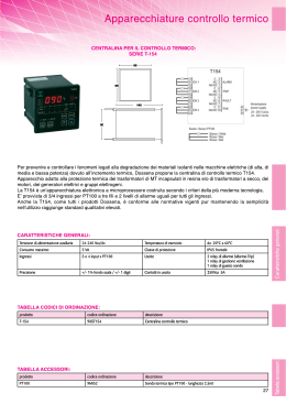
953933
ENGLISH................................................................ 1
ITALIANO............................................................... 4
ENGLISH
AUXILIARY BOARD INSTALLATION
AUX relay
DANGER, OBLIGATORY AND PROHIBITION SIGNS
Programmable
multifunction relay.
Danger of electric shock.
RS-485
Terminal block for
connecting an RS-485
serial line.
General danger.
1. SAFETY INSTRUCTIONS
These instructions give information on how to install the
auxiliary board. These operations can only be carried
out by suitably qualified experts who have read and
understood the instruction manual.
2.1 PI Relay
The PI relay is disabled when the inverter is disconnected
from the grid.
In addition:
NC
COM
• The apparatus must be installed in compliance with
national and local regulations.
• Carry out electric installation following relative
regulations and accident prevention laws.
• The inverter must only be connected to a power
system with neutral conductor connected to earth.
• The connection section must only be opened by
qualified technicians. Before opening the section,
make sure the panel side (DC) and network side
(AC) have been disconnected. Before intervening
on the connections, wait at least 5 minutes for the
condensers to be completely discharged.
• Only use the apparatus for applications that are in
compliance with the prescribed use.
• Do not install the apparatus in damp or wet areas, or
where it can be reached by rainfall.
• Do not use cables with deteriorated insulation.
• Information on installation, starting and maintenance
given in this manual is only for qualified technicians.
Electric shocks can cause death.
PI
RELAY
NA
INVERTER OFF
The PI relay activates when the inverter is connected to the
grid.
NC
COM
PI
RELAY
NA
INVERTER ON
2.2 Relay AUX
Il relè AUX (multifunzione programmabile) può essere
impostato con una delle seguenti funzionalità:
• come contatto di segnalazione guasto o funzionamento;
• come contatto per la funzione autoconsumo.
2. DESCRIPTION
The auxiliary relay board can be used for different purposes.
It is supplied with:
2.2.1 Connecting the AUX relay as a fault or operation
signal contact
If the multifunction relay is activated in this mode, the contact
changes state following an inverter alarm.
If a fault signal from several inverters is required, connect all
the AUX relays (COM-NA) of the various inverters in parallel:
PI relay
NA
NC
COM
AUX
RELAY
INVERTER (n)
NA
NC
COM
AUX
RELAY
INVERTER 2
NA
NC
-1-
COM
INVERTER 1
The relay activates
together with the inverter
grid relay.
AUX
RELAY
If a correct operation signal is required, connect all the AUX
relays (COM-NC) of the various inverters in series:
NC
COM
AUX
RELAY
NA
INVERTER (n)
NA
NC
COM
INVERTER 2
NA
NC
COM
INVERTER 1
AUX
RELAY
Insert the 4 spacers into their relative seats.
Insert the auxiliary relay board.
2
AUX
RELAY
1
2.2.2 AUX relay connection as a contact for selfconsumption
AUX
RELAY
Connect the auxiliary relay board to the panel board using
the supplied cables.
Fix the supplied cable glands to the base of the inverter.
NC
COM
NA
3
1
4
2
K1
If the multifunction relay is activated in this mode, the contact
changes state if the available inverter power exceeds a
certain threshold.
2.3 RS-485
A monitoring system that is compatible with VALENIA
inverters can be connected to the RS-485 terminal block. Up
to a maximum of 32 inverters can be connected, as shown
in the figure:
MONITORING
SYSTEM
+5V
N
P
0V
AURUS
AURUS
AURUS
ID = 001
ID = 002
ID = 032
+5V
N
P
0V
+5V
N
P
+5V
0V
N
P
Connect to the PI, AUX and/or RS-485 terminal blocks as
described previously.
0V
Double insulation must be guaranteed inside the inverter
between the DC connectors, the AC connectors and
the connectors coming from the auxiliary relay board
terminal block.
The cables coming from the auxiliary relay board terminal
block must exit externally from the inverter through the
previously mounted cable glands.
3. INSTALLATION
Remove the door to open the connection area.
2
Close the inverter once all the connections have been made.
4. SETTING THE AUX RELAY (MULTIFUNCTION)
OPERATION MODE
The multifunction relay is factory set at disabled. If this
relay is to be used, enter the “SETTINGS” menu (see
instruction manual supplied with the inverter) and select
“MULTIFUNCTION RELAY” Press ENTER to access the
following sub-menus:
1
Unscrew the 3 M6 screws and remove the lower part from the
inverter (do not disconnect the wiring).
2
1
1
1
-2-
4.1 ALARM
If “STATUS RELAY: ON” is selected in this mode,
Selecting “MIN. RUN TIME:”
determines the minimum time of self-consumption operation.
The maximum duration depends on the available power
coming from the photovoltaic modules.
the AUX relay state changes following an inverter alarm.
4.2 SELF-CONSUMPTION
If “SELF-CONSUMPTION” is selected, the following display
appears:
Default Adjustment field
STATUS RELAY
OFF
Step
OFF/ON
-
START POWER
1500W From 100 W to nominal power 100W
START TIME
30min From 0 to 1440 min
1min
MIN RUN TIME
120min From 0 to 1440 min
1min
5. SETTING THE ADDRESS OF EACH SINGLE INVERTER
FOR REMOTE MONITORING.
If several inverters have to be monitored (using the RS-485
terminal block), each one must have its own address.
To set an address:
SETTINGS MENU:
Selecting “STATUS RELAY: ON”
enables the relay to work in this manner.
Select:
ADDRESS:
Selecting “START POWER:”
determines the power at which the relay activates.
Selecting “START TIME:”
Set the address of each individual inverter. The numbers to
be assigned can range from 1 to 32.
determines the minimum time for which the power must
exceed the minimum threshold before the relay activates.
6. TECHNICAL DATA: PI and AUX RELAYS
Maximum AC commutation voltage
-3-
250Vac
Maximum AC commutation current
2Aac
Maximum DC commutation voltage
30Vdc
Maximum DC commutation current
2Adc
ITALIANO
INSTALLAZIONE SCHEDA AUSILIARIA
Relay AUX
LEGENDA SEGNALI DI PERICOLO, D’OBBLIGO E
DIVIETO
Relay multifunzione
programmabile.
Pericolo shock elettrico.
RS-485
Morsettiera per il
collegamento di una linea
seriale RS-485.
Pericolo generico.
1. ISTRUZIONI DI SICUREZZA
Le presenti istruzioni contengono informazioni
relative all’installazione della scheda ausiliaria. Queste
operazioni possono essere svolte solo da persone in
possesso di adeguata qualifica e che abbiano letto e
compreso il manuale d’istruzione.
2.1 Relay PI
Il relè PI è disattivato quando l’inverter è sconnesso dalla rete
NC
Inoltre:
COM
PI
RELAY
NA
INVERTER OFF
• L’installazione dell’apparecchio dovrà essere
eseguita in ottemperanza alle normative nazionali e
locali.
• Eseguire l’installazione elettrica secondo le previste
norme e leggi antinfortunistiche.
• L’inverter deve essere collegato esclusivamente ad
un sistema di alimentazione con conduttore di neutro
collegato a terra.
• Il vano collegamenti va aperto solo da personale
qualificato. Prima di aprire il vano accertarsi di aver
sezionato il lato pannelli (DC) e il lato rete (AC). Prima
di intervenire sui collegamenti attendere un tempo di
almeno 5 minuti in modo che i condensatori siano
completamente scarichi.
• Utilizzare l’apparecchio esclusivamente per le
applicazioni conformi all’uso prescritto.
• Non installare l’apparecchio in luoghi umidi o bagnati
o sotto la pioggia.
• Non utilizzare cavi con isolamento deteriorato.
• Le informazioni per l’installazione, messa in servizio
e manutenzione contenute nel presente manuale
riguardano esclusivamente personale tecnico
qualificato. Una scossa elettrica può avere esiti
mortali.
Quando l’inverter si connette alla rete il relè PI si attiva.
NC
COM
PI
RELAY
NA
INVERTER ON
2.2 Relay AUX
Il relè AUX (multifunzione programmabile) può essere
impostato con una delle seguenti funzionalità:
• come contatto di segnalazione guasto o funzionamento;
• come contatto per la funzione autoconsumo.
2.2.1 Collegamenti del relay AUX come contatto di
segnalazione guasto o di funzionamento
Se il relè multifunzione viene attivato in questa modalità, il
contatto cambia di stato a seguito di un allarme comparso
sull’inverter.
Se si vuole ottenere una segnalazione di guasto su più
inverter bisogna collegare in parallelo tutti i relays AUX
(COM-NA) dei vari inverter:
NA
NC
COM
AUX
RELAY
INVERTER (n)
NA
NC
COM
AUX
RELAY
INVERTER 2
NA
NC
Relay PI
COM
INVERTER 1
2. DESCRIZIONE
La scheda ausiliaria può essere impiegata per diverse
finalità. Essa è fornita con:
AUX
RELAY
Il relay si attiva
contemporaneamente al
relè di rete dell’inverter.
Se invece si vuole una segnalazione di funzionamento
corretto bisogna collegare in serie tutti i relays AUX (COMNC) dei vari inverter:
-4-
NC
COM
AUX
RELAY
NA
INVERTER (n)
NA
NC
COM
INVERTER 2
NA
NC
COM
INVERTER 1
AUX
RELAY
Inserire i 4 distanziali nelle sedi predisposte.
Inserire la scheda ausiliaria.
2
AUX
RELAY
1
2.2.2 Collegamenti del relay AUX come contatto per la
funzione autoconsumo
AUX
RELAY
Collegare la scheda ausiliaria alla scheda pannello con il
cablaggio in dotazione.
Fissare i pressacavi in dotazione sul fondo dell’inverter.
NC
COM
NA
3
1
4
2
K1
Se il relè multifunzione viene attivato in questa modalità, il
contatto cambia di stato se la potenza disponibile dall’inverter
supera una certa soglia.
2.3 RS-485
La morsettiera RS-485 permette il collegamento ad un
sistema di monitoraggio compatibile con gli inverter
VALENIA. Possono essere collegati fino ad un massimo di
32 inverter come evidenziato in figura:
MONITORING
SYSTEM
+5V
N
P
0V
AURUS
AURUS
AURUS
ID = 001
ID = 002
ID = 032
+5V
N
P
0V
+5V
N
P
+5V
0V
N
P
Effettuare i collegamenti ai relays PI, AUX e/o morsettiera
RS-485 come descritto precedentemente.
0V
All’interno dell’inverter deve essere garantito un doppio
isolamento tra conduttori DC, conduttori AC e conduttori
provenienti dalle morsettiere della scheda ausiliaria.
I cavi provenienti dalle morsettiere della scheda ausiliaria
devono uscire all’esterno dell’inverter attraverso gli appositi
pressacavi montati in precedenza.
3. INSTALLAZIONE
Aprire il vano collegamenti togliendo lo sportello.
Una volta eseguiti tutti i collegamenti richiudere l’inverter.
2
4. IMPOSTAZIONE DELLA MODALITA’ DI FUNZIONAMENTO
DEL RELE’ AUX (MULTIFUNZIONE).
L’impostazione di fabbrica prevede che il relay multifunzione
sia disabilitato. Se si desidera impiegare tale relay bisognare
entrare nel menù “IMPOSTAZIONI” (vedi manuale
d’istruzione fornito con l’inverter) e selezionare “RELE
MULTIFUNZIONE”. Premendo il tasto ENTER si ha accesso
al seguente sottomenù:
1
Svitare le 3 viti M6 e rimuovere la parte inferiore dall’inverter
(non scollegare i cablaggi).
2
1
1
1
-5-
4.1 ALLARME
In questa modalità selezionando “STATUS RELAY: ON”
Selezionando “MIN RUN TIME:”
si determina il tempo minimo della funzione di autoconsumo.
La durata massima dipende dalla potenza disponibile,
proveniente dai moduli fotovoltaici.
il relay AUX cambia di stato a seguito di un allarme comparso
sull’inverter.
Default Campo regolazione
4.2 AUTOCONSUMO
Selezionando “AUTOCONSUMO” compare la seguente
schermata:
STATUS RELAY
OFF
Step
OFF/ON
-
START POWER
1500W Da 100W a Potenza nominale 100W
START TIME
30min Da 0 a 1440min
1min
MIN RUN TIME
120min Da 0 a 1440min
1min
5. IMPOSTAZIONE INDIRIZZO DI OGNI SINGOLO
INVERTER PER MONITORAGGIO DA REMOTO.
Nel caso si debbano monitorare più inverter (attraverso la
morsettiera RS-485) ognuno deve avere il proprio indirizzo.
Per impostarlo:
MENU IMPOSTAZIONI:
Selezionando “STATUS RELAY: ON”
si abilita il relay a funzionare in questa modalità.
Selezionando “START POWER:”
Selezionare:
INDIRIZZO:
si determina la potenza a partire dalla quale il relay viene
attivato.
Impostare l’indirizzo di ogni singolo inverter. I numeri da
assegnare possono andare da 1 a 32.
Selezionando “START TIME:”
6. DATI TECNICI RELAYS PI e AUX
si determina il tempo minimo per il quale la potenza deve
superare la soglia minima prima che il relay venga attivato.
Tensione di commutazione CA massima
-6-
250Vac
Corrente di commutazione CA massima
2Aac
Tensione di commutazione CC massima
30Vdc
Corrente di commutazione CC massima
2Adc
-7-
-8-
Scarica