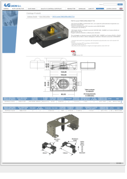
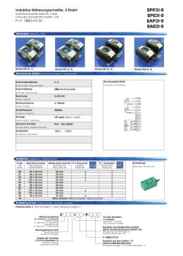
25
FINECORSA ESTERNI ED INDICATORI DI POSIZIONE
EXTERNAL LIMIT SWITCHES AND POSITION INDICATORS
Indicatore visivo di posizione
Position indicator
CARATTERISTICHE PRINCIPALI TECHNICAL DATA
Esecuzione in plastica versione Namur:
Sfera in materiale plastico nero;fasce indicatrici in materiale plastico
giallo.
N.B. le fasce si possono combinare in modo da segnalare valvole
normalmente chiuse, normalmente aperte e valvola tre vie con sfera
a “L” o “T”.
Esecuzione a semaforo con settori verdi e rossi in policarbonato.
Montaggio diretto per attuatori a norma VDI/VDE 3845.
Esecuzione in metallo:
Disco in alluminio verniciato nero; freccia in alluminio verniciato giallo.
N.B. la freccia si può posizionare in modo da segnalare valvole normalmente aperte o normalmente chiuse.
Plastic execution as per Namur:
Ball in black plastic; indicating bands in yellow.
NOTE: Bands can be combined so as to indicate Normally Open or
Normally Closed valves, as well as 3-way valves with “L” or “T” port.
Red-green execution. Direct mounting on actuators as per VDI/VDE
3845 specification.
1
3
2
Metal execution:
Disc in black painted aluminium; arrow in yellow painted aluminium.
NOTE: the arrow can be positioned so as to indicate Normally Open
or Normally Closed valves.
1
Indicatore a semaforo
Red-green indicator
Indicatore in metallo
Metal indicator
2
3
Indicatore in plastica
Plastic indicator
TABELLA DIMENSIONALE indicatore in plastica NAMUR DIMENSION TABLE plastic indicator NAMUR execution
DA 15 DA 30
------ SR 15
Attuatore Actuator
Attuatore Actuator
Indicatore Indicator
Indicatore 3 vie“T” 3 way“T”indicator
Indicatore 3 vie“L” 3 way“L”indicator
A
B
mm.
mm.
DA 45 DA 60
------ SR 30
KI02PP10
KI03PP10
KI04PP10
27
30
DA 90
SR 45
DA 120 DA 180 DA 240 DA 360 DA 480 DA 720 DA 960 DA 1440 DA 1920
SR 60 SR 90 SR 120 SR 180 SR 240 SR 360 SR 480 SR 720 SR 960
KI02PP16
---------------KI03PP16
---------------KI04PP16
---------------42
---------------48
----------------
TABELLA DIMENSIONALE indicatore a semaforo NAMUR DIMENSION TABLE red-green indicator NAMUR execution
Attuatore Actuator
Attuatore Actuator
Indicatore Indicator
DA 15 DA 30
------ SR 15
DA 45
------
DA 60
SR 30
DA 90
SR 45
DA 120 DA 180 DA 240 DA 360 DA 480 DA 720 DA 960 DA 1440 DA 1920
SR 60 SR 90 SR 120 SR 180 SR 240 SR 360 SR 480 SR 720 SR 960
KISD0370
KISD0170
TABELLA DIMENSIONALE indicatore in metallo NAMUR DIMENSION TABLE metal indicator NAMUR execution
Indicatore Indicator
KI01VR14
Misure superiori a DA1920 a richiesta
Size bigger than DA1920, on request
26
FINECORSA ESTERNI ED INDICATORI DI POSIZIONE
EXTERNAL LIMIT SWITCHES AND POSITION INDICATORS
Kit per montaggio di finecorsa di prossimità M12
Mounting kit for proximity limit switches M12
A richiesta disponibili kit per montaggio di finecorsa di prossimità M18 e
misure superiori a DA1920
Misura/Size
Codice/Code
DA 8
KBF85008
DA 15÷DA 90
KBF85015
DA 120÷DA 480
KBF85060
DA 720÷DA1920
KBF85960
On request are available kits for mounting proximity limit switches M18 e
size bigger than DA1920
KFIN1-KFIN2
1 FINECORSA/1 LIMIT SWITCH
Misura/Size
Codice/Code
2 FINECORSA/2 LIMIT SWITCHES
Misura/Size
Codice/Code
DA 8
KFIN1008
DA 8
KFIN2008
DA 15÷DA 90
KFIN1015
DA 15÷DA 90
KFIN2015
DA 120÷DA 480
KFIN1060
DA 120÷DA 480
KFIN2060
DA 720÷DA1920
KFIN1960
DA 720÷DA1920
KFIN2960
Misure superiori a DA1920 a richiesta Sizes bigger than DA1920,on request
TECHNICAL DATA
CARATTERISTICHE PRINCIPALI
1 interruttore di prossimità induttivo M12 collegamento a 2 fili NO
Tensione di alimentazione: 24÷240V AC; 24÷210V DC.
Corrente commutabile: 0,2A max
Grado di protezione: IP 68
Lunghezza cavo: 3m
Temperatura di funzionamento: da -25°C a +70°C
Segnalazione stato di uscita tramite LED anulare.
Comprensivo di kit per il montaggio sui modelli DA e SR composto
da una basetta fissata al corpo dell’attuatore e da una camma
montata sull’albero dello stesso.
1 M12 inductive limit switch with NO wire connection
Supply voltage: 24÷240V AC; 24÷210V DC.
Commutable current: 0,2A max
Protection rate: IP 68
Cable length: 3m
Working temperature: from -25°C to +70°C
Limit switch working signalled by ring LED.
Mounting kit included on DA and SR models. It is composed by a
plate fixed on the body of the actuator and a cam mounted on its
shaft.
A richiesta disponibile interruttore di prossimità induttivo M18
On request it is available an inductive limit switch M18
Schema di funzionamento Working scheme
marrone brown
D
blu blue
TABELLA DIMENSIONALE DIMENSION TABLE
A
B
C
D
mm.
mm.
mm.
mm.
54
34
38
50
54
34
38
50
54
44
48
50
64
44
48
50
27
FINECORSA ESTERNI ED INDICATORI DI POSIZIONE
EXTERNAL LIMIT SWITCHES AND POSITION INDICATORS
FN90
12
tipo di connessione/ connection type
22
con cavo 2 m, codice P+F: NCN4-12GM35-N0 2
2m. cable, P+F code: NCN4-12GM35-N0
21
con connettore, codice P+F: NCN4-12GM35-N0-V1
with connector, code P+F: NCN4-12GM35-N0-V1
CARATTERISTICHE PRINCIPALI
TECHNICAL DATA
Finecorsa induttivo NAMUR M12 2 fili DC
Tensione di alimentazione: 8V DC
Corrente assorbita: 1 mA chiuso, 3 mA aperto.
Grado di protezione IP 67
Temperatura di funzionamento: da -25°C a +100°C Segnalazione
stato di uscita tramite LED anulare.
Conforme alle norme EN 60947-5-6
Kit di montaggio da ordinare a parte (KBF8__) a seconda
dell’altezza dell’albero attuatore, vedi pag. 28
Per la versione con connettore è necessario ordinare anche il
cavo, vedi pag. 36
Atex EExia II CT6, vedere istruzioni
Applicabile fino a SIL 2 secondo IEC61508
M12 inductive limit switch, 2-DC NAMUR wire
Supply voltage: 8V DC
Current consumption: 1 mA closed, but open 3.
Protection rate: IP 67
Working temperature: from -25 ° C to +100 ° C
Limit switch working signalled by ring LED.
According to EN 60947-5-6
Mounting kit to be ordered separately (KBF8__) depending on the
height of the actuator shaft, see page. 28
For the version with connector, you have to order also the cable,
see page. 36
Atex version EExia II CT6, see instructions
Usable up to SIL 2 according to IEC61508
FI90
12
tipo di connessione/connection type
32
con cavo 2 m, codice P+F: NBN4-12GM50-E2
2 mt. cable, P+F code: NBN4-12GM50-E2
31
con connettore, codice P+F: NBN4-12GM50-E2-V1
with connector, code P+F:NBN4-12GM50-E2-V1
CARATTERISTICHE PRINCIPALI
TECHNICAL DATA
Finecorsa induttivo PNP M12 3 fili DC
Tensione di alimentazione: 10÷30 V DC
Corrente assorbita: 0÷12 mA
Grado di protezione IP 67
Temperatura di funzionamento: da -25°C a +70°C
Segnalazione stato di uscita tramite LED anulare.
Conforme alle norme EN 60947-5-2
Kit di montaggio da ordinare a parte (KBF8__) a seconda
dell’altezza dell’albero attuatore, vedi pag. 28
Per la versione con connettore è necessario ordinare anche il
cavo, vedi pag. 36
3-wire DC PNP M12 inductive limit switch
Suppy voltage: 10 ÷ 30 V DC
Current consumption: 0 ÷ 12 mA
Protection rate IP 67
Working temperature: from -25°C to +70°C
Limit switch working signalled by ring LED.
According to EN 60947-5-2
Mounting kit to be ordered separately (KBF8__) depending on
the height of the actuator shaft, see page. 28
For the version with connector, you have to order also the
cable, see page. 36
FI90
12
tipo di connessione/connection type
CARATTERISTICHE PRINCIPALI
Finecorsa induttivo M 12 2 fili DC
Tensione di alimentazione: 6÷60 V DC
Corrente assorbita: 4÷100 mA
Grado di protezione IP 67
Temperatura di funzionamento: da -25°C a +70°C
Segnalazione stato di uscita tramite LED anulare.
Conforme alle norme EN 60947-5-2
Kit di montaggio da ordinare a parte (KBF8__) a seconda
dell’altezza dell’albero attuatore, vedi pag. 28
Per la versione con connettore è necessario ordinare anche il
cavo, vedi pag. 36
22
con cavo 2 m, codice P+F: NBN4-12GM40-Z0
2 mt. cable, P+F code: NBN4-12GM40-Z0
21
con connettore, codice P+F: NBN4-12GM40-Z0-V1
with connector, code P+F:NBN4-12GM40-Z0-V1
TECHNICAL DATA
2-wire DC M12 inductive limit switch
Supply voltage: 6 to 60 V DC
Current consumption: 4 to 100 mA Protection rate: IP 67
Working temperature: from -25°C to +70°C
Limit switch working signalled by ring LED
According to EN 60947-5-2
Mounting kit to be ordered separately (KBF8__) depending on
the height of the actuator shaft, see page. 28
For the version with connector, you have to order also the
cable, see page. 36
28
FINECORSA ESTERNI ED INDICATORI DI POSIZIONE
EXTERNAL LIMIT SWITCHES AND POSITION INDICATORS
Kit per montaggio di finecorsa meccanici o
pneumatici
Mounting kit for mechanical or pneumatic
limit switches
Misura/Size
Codice/Code
DA 15÷DA 90
KBF68015
DA 120÷DA 480
KBF68060
DA 720÷DA1920
KBF68960
Misure superiori a DA1920 a richiesta
Sizes over DA1920 available on request
KFE3A
1 FINECORSA/1 LIMIT SWITCH
2 FINECORSA/2 LIMIT SWITCHES
Misura/Size
Codice/Code
Misura/Size
Codice/Code
DA 15÷DA 90
KFE3A1015
DA 15÷DA 90
KFE3A2015
DA 120÷DA 480
KFE3A1120
DA 120÷DA 480
KFE3A2120
DA 720÷DA1920
KFE3A1720
DA 720÷DA1920
KFE3A2720
Misure superiori a DA 1920 a richiesta Sizes over DA1920 available on request
CARATTERISTICHE PRINCIPALI
Finecorsa meccanici del tipo a pulsante conformi alle norme:
Macchine: IEC 60947-5-1, EN 60947-5-1, UL 508,
CSA C22-2 n° 14
Prodotti: IEC 60204-1; EN 60204-1
Corpo in tecnopolimero
Grado di protezione IP 65 secondo IEC 60529
Cavo d’uscita flessibile a 4 conduttori (lunghezza 1m)
Temperatura di utilizzo: da -25°C a +70°C
Possono essere montati sui modelli DA e SR tramite un kit composto da una basetta fissata al corpo dell’attuatore e da una
camma montata sull’albero dello stesso.
TECHNICAL DATA
Mechanical, button limit switches as per:
machinery:IEC 60947-5-1, EN 60 947-5-1, UL 508,
CSA C22-2 n° 14
product: EC 60204-1; EN 60204-1
Body in technopolymer
Protection: IP 65 as per IEC 60529
Flexible output cable with 4 conductors (lenght 1 m)
Working temperature: from -25°C to +70°C
It can be mounted onto DA or SR models using a kit which contains a mounting plate and a cam fixed to the actuator body.
Schema di funzionamento Working scheme
A
B
C
D
mm.
mm.
mm.
mm.
(nero black)
(marrone brown)
(nero black)
(blu blue)
TABELLA DIMENSIONALE DIMENSIONS TABLE
76
31
38
60
76
41
48
70
(verde-giallo)
(green-yellow)
86
41
48
70
29
FINECORSA ESTERNI ED INDICATORI DI POSIZIONE
EXTERNAL LIMIT SWITCHES AND POSITION INDICATORS
KFN41-KFN42
1 FINECORSA/1 LIMIT SWITCH
2 FINECORSA/2 LIMIT SWITCHES
Misura/Size
Codice/Code
Misura/Size
Codice/Code
DA 15÷DA 90
KFN41015
DA 15÷DA 90
KFN42015
DA 120÷DA 480
KFN41120
DA 120÷DA 480
KFN42120
DA 720÷DA1920
KFN41960
DA 720÷DA1920
KFN42960
Misure superiori a DA1920 a richiesta Sizes over DA1920 available on request
CARATTERISTICHE PRINCIPALI
1 finecorsa meccanico del tipo a pulsante conforme alle norme IEC
947-5-1,EN 60 945-5-1,UL 508,Omologazione CSA A300-UL 300
Listed
Grado di protezione IP 67
Ingresso cavo filettato Pg 11
Temperatura di utilizzo: da -25°C a +70°C
Comprensivo di kit per il montaggio sui modelli DA e SR composto
da una basetta fissata al corpo dell’attuatore e da una camma montata sull’albero dello stesso.
TECHNICAL DATA
1 mechanical button limit switch according to IEC 947-5-1, EN 60
945-5-1, UL 508, CSA A300-UL 300 approved Listed
Protection rate: IP 67
Threaded cable input Pg 11
Working temperature: from -25°C a +70°C
Mounting kit included on DA and SR models. It is composed by a
plate fixed on the body of the actuator and a cam mounted on its
shaft.
Schema di funzionamento Working scheme
FORO PER PRESSACAVI HOLE FOR CABLE GLAND
TABELLA DIMENSIONALE DIMENSIONS TABLE
A
B
C
D
mm.
mm.
mm.
mm.
90
45
38
60
90
55
48
70
100
55
48
70
30
FINECORSA ESTERNI ED INDICATORI DI POSIZIONE
EXTERNAL LIMIT SWITCHES AND POSITION INDICATORS
Finecorsa pneumatico Pneumatic limit switch
KFN11-KFN12
1 FINECORSA/1 LIMIT SWITCH
2 FINECORSA/2 LIMIT SWITCHES
Misura/Size
Codice/Code
Misura/Size
Codice/Code
DA 15÷DA 90
KFN11015
DA 15÷DA 90
KFN12015
DA 120÷DA 480
KFN11060
DA 120÷DA 480
KFN12060
DA 720÷DA1920
KFN11960
DA 720÷DA1920
KFN12960
Misure superiori a DA 1920 a richiesta Sizes over DA1920 available on request
CARATTERISTICHE PRINCIPALI
TECHNICAL DATA
1 finecorsa pneumatico miniaturizzato con attacchi a cartuccia tubo
∅4x2
Temperatura di utilizzo: da +5°C a +70°C
Pressione max. di esercizio: 10 bar
Fluido di alimentazione: aria filtrata e lubrificata alla temperatura di
50°C max.
Portata a 6 bar. con ∆p=1:90 NI/min
Diametro di passaggio: 2,2 mm
Comprensivo di kit per il montaggio sui modelli DA e SR composto da una basetta fissata al corpo dell’attuatore e da una camma
mon¬tata sull’albero dello stesso.
1 miniaturized pneumatic limit switch with cartridge connections
pipe ∅4x2
Working temperature: from +5°C to +70°C
Max working pressure: 10 bar
Operating media: lubricated and filtered air at a temperature of max
50°C.
Flow at 6 bar. with ∆p=1:90 NI/min
Bore: 2,2 mm
Mounting kit included on DA and SR models. It is composed by a
plate fixed on the body of the actuator and a cam mounted on its shaft
Schema di funzionamento Working scheme
A
B
C
D
mm.
mm.
mm.
mm.
TABELLA DIMENSIONALE DIMENSIONS TABLE
65
65
75
38
48
48
32,5
60
40
70
40
70
31
FINECORSA ESTERNI ED INDICATORI DI POSIZIONE
EXTERNAL LIMIT SWITCHES AND POSITION INDICATORS
KBF06
Kit per montaggio finecorsa antideflagranti
Mounting kit for explosion proof limit switches
Misura/Size
Codice/Code
DA 15÷DA 90
KBF66015
DA 120÷DA 1920
KBF66060
Misure superiori a DA1920 a richiesta
Sizes over DA1920 available on request
KFN61-KFN62
1 FINECORSA/1 LIMIT SWITCH
2 FINECORSA/2 LIMIT SWITCHES
Misura/Size
Codice/Code
Misura/Size
Codice/Code
DA 15÷DA 90
KFN61015
DA 15÷DA 90
KFN62015
DA 120÷DA 480
KFN61060
DA 120÷DA 480
KFN62060
Misure superiori a DA1920 a richiesta
Sizes over DA1920 available on request
TECHNICAL DATA
1 finecorsa antideflagrante con custodia in lega leggera viteria in
acciaio inox verniciatura esterna epossivinilica RAL 7000
Temperatura di utilizzo: da -10°C a +60°C
Numero di manovre: 300/ora max
Elemento di contatto unipolare, 1NA+1NC: Imax 10A Vmax
220Vca-220Vcc
Collegamento: morsetti a vite sezione massima 2,5 mm2
Grado di protezione: IP 65
Grado di antideflagranza: EExd IIC T6
Certificato di conformità: CESI EX-90.C.003
Connessione elettrica: 1/2” gas
Comprensivo per il kit di montaggio sui modelli DA e SR composto da una basetta fissata a corpo dell’attuatore e da una camma
montata sull’albero dello stesso.
134
74
136
1 explosion-proof limit switch with light-alloy housing, stainless steel
screws, vinyl-epoxy painted, RAL 7000
Working temperature: from -10°C to +60°C
Nr. Of cycles: max. 300/h
Unipolar contact element, 1NA+1NC: Imax 10A Vmax 220Vca
220Vcc
Connection: screw terminal, section 2,5 mm² max
Protection rate: IP 65
Explosion-proof level: EExd IIC T6
Certificate of compliance: CESI EX-90.C.003
Electrical connection: 1/2” gas
Mounting kit included on DA and SR models. It is composed by a
plate fixed on the body of the actuator and a cam mounted on its
shaft
Schema di funzionamento Working scheme
32
FINECORSA ESTERNI ED INDICATORI DI POSIZIONE
EXTERNAL LIMIT SWITCHES AND POSITION INDICATORS
Protezioni per finecorsa
Switch protection
KZN00
CARATTERISTICHE PRINCIPALI TECHNICAL DATA
Protezioni per finecorsa di tipo pneumatico, meccanico e
induttivo tranne per KFN61-KFN62.
Materiale: alluminio anodizzato.
Possono essere montate su tutti i modelli di attuatori DA e SR.
Protection for mechanical, pneumatic and inductive limit
switches a part from KFN61-KFN62
Material: anodized aluminium
It can be mounted onto all DA and SR models.
Misura/Size
Codice/Code
DA 15÷DA 90 SR15÷SR45
KZN00014
DA 480÷DA1920 SR240÷SR960
KZN00022
33
FINECORSA ESTERNI ED INDICATORI DI POSIZIONE
EXTERNAL LIMIT SWITCHES AND POSITION INDICATORS
Kit per finecorsa Pepperl+Fuchs a montaggio
diretto con altezza albero attuatore 20 mm
Misura/Size
Codice/Code
altezza albero
shaft eight
20mm
KBFPBT32
Misura/Size
Codice/Code
altezza albero
shaft eight
30mm
KBFPBT33
Mounting kit between Pepperl+Fuchs limit
switches and actuator with shaft height 20 mm
Kit per finecorsa Pepperl+Fuchs a montaggio
diretto con altezza albero attuatore 30 mm
Mounting kit between Pepperl+Fuchs limit
switches and actuator with shaft height 30 mm
FN90
22
tipo di connessione/ connection type
FI90
22
22
tipo di connessione/ connection type
31
25
con connettore, codice P+F:
NBN3-F25-E8-V1
with connector, code P + F:
NBN3-F25-E8-V1
21
con cavo 2m, codice
P+F: NCN3-F25-N4-0,14
with 2 mt. cable, code
P+F: NCN3-F25-N4-0,14
con cavo 5m, codice
P+F: NCN3-F25-N4-5
with 5mt cable, code
P+F: NCN3-F25-N4-5
con connettore, codice P+F:
NCN3-F25-N4-V1
with connector, code P+F: NCN3F25-N4-V1
CARATTERISTICHE
TECHNICAL DATA
CARATTERISTICHE
TECHNICAL DATA
Finecorsa induttivo PNP 3 fili
DC montaggio diretto.
Tensione di alimentazione:
10÷30 V DC
Corrente assorbita: 0÷200
mA Grado di protezione IP 67
Temperatura di funzionamento:
da -25°C a +70°C
Segnalazione stato di uscita
tramite LED.
Conforme alle norme EN
60947-5- 2 Richiede attuatore
con attacco NAMUR superiore
80x30 con altezza albero 20 o
30 mm.
Kit di montaggio da ordinare a
parte (KBFPBT32-KBDPBT33)
a seconda dell’altezza dell’albero attuatore vedi pag. 28
E’ necessario anche ordinare il
cavo connettore vedi pag. 36
3-wire DC PNP inductive limit
switch, direct mounting.
Supply voltage: 10÷30 V DC
Current consumption: 0÷200
mA
Protection rate: IP 67
Working temperature: from
-25°C to +70°C
Limit switch working signalled
by LED.
According to: EN 60947-5- 2
It needs actuator with Namur
connection bigger than 80x30
and with shaft-height 20 or 30
mm.
Mounting kit has to be ordered
separately (KBFPBT32KBDPBT33) according to the
shaft height, see page 28
You need to order also the wire
connector, see page 36.
Finecorsa NAMUR PNP 2 fili DC
montaggio diretto.
Tensione di alimentazione: 8 VDC
Corrente assorbita: 1 mA chiuso,
3mA aperto.
Grado di protezione IP 67 Temperatura di funzionamento: da -25°C
a +100°C
Segnalazione stato di uscita
tramite LED.
Conforme alle norme EN 609475-6 Richiede attuatore con attacco NAMUR superiore 80x30 con
altezza albero 20 o 30 mm.
Kit di montaggio da ordinare a
parte (KBFPBT32-KBDPBT33) a
seconda dell’altezza dell’albero
attuatore vedi pag. 281
E’ necessario anche ordinare il
cavo connettore vedi pag. 36
ATEX: II2G EEx ia IIC T6,
categorie 2G;3G;3D, vedere
istruzioni
2-wire PC PNP Namur limit
switch, direct mounting.
Supply voltage: 8 VDC
Current consumption: 1 mA
closed, 3mA opened.
Protection rate : IP 67
Working temperature: from -25°C
to +100°C
Limit switch working signalled
by LED.
According to: EN 60947-5-6
It needs actuator with Namur
connection bigger than 80x30
and with shaft-height 20 or 30
mm.
Mounting kit has to be ordered separately (KBFPBT32KBDPBT33) according to the
shaft height, see page 28
You need to order also the wire
connector, see page 36.
ATEX: II2G EEx ia IIC T6, categories 2G;3G;3D, see instruction
34
FINECORSA ESTERNI ED INDICATORI DI POSIZIONE
EXTERNAL LIMIT SWITCHES AND POSITION INDICATORS
Cavo di connessione per finecorsa Pepperl+Fuchs
con uscita connettore (modello V1)
Connection cable for limit switches Pepperl+Fuchs
with connector output (model V1)
Size
Code
cavo da 2 m
KBCP2M00
cavo da 5 m
KBCP5M00
35
FINECORSA ESTERNI ED INDICATORI DI POSIZIONE
EXTERNAL LIMIT SWITCHES AND POSITION INDICATORS
Atex pneumatic limit switch
model: KFN22015 - KFN21015
30
Schema di funzionamento Working scheme
CARATTERISTICHE PRINCIPALI TECHNICAL DATA
Finecorsa pneumatico miniaturizzato con attacchi a cartuccia tubo
ø4 e M5 (assiali o laterali)
Temperatura di utilizzo: da -10°C a +60°C
Pressione max. di esercizio: 10 bar.
Fluido di alimentazione: aria filtrata e lubrificata alla temperatura di
50°C max.
Portata a 6 bar. con ∆p=1: 60 Nl/min.
Diametro di passaggio: 2,5 mm.
Può essere montato sui modelli DA ed SR tramite un kit composto
da una basetta fissata al corpo dell’attuatore e da una camma
montata sull’albero dello stesso.
Normativa ATEX II 2 GD
Miniaturized pneumatic limit switch with cartridge connections;
pipe ø4 and M5 (axial or sideward)
Working temperature: from -10°C to +60°C
Max working pressure: 10 bar
Operating media: lubricated and filtered air at a temperature of
50°C max.
Flow at 6 bar with ∆p=1: 60 Nl/min.
Bore: 2,5 mm.
It can be mounted onto DA or SR models using a kit which contains a mounting plate and a cam fixed to the actuator body.
According to ATEX II 2 GD
TABELLA DIMENSIONALE DIMENSION TABLE
DA 15 DA 30 DA 45 DA 60 DA 90 DA 120 DA 180 DA 240 DA 360
Attuatore Actuator
------ SR 15 ------ SR 30 SR 45 SR 60 SR 90 SR 120 SR 180
Attuatore Actuator
kit
KBF68015
KBF68060
KFN21015
KFN21120
kit 1 finecorsa kit 1 limit switch
KFN22015
KFN22120
kit 2 finecorsa kit 2 limit switches
A
mm.
60
60
B
mm.
32,5
40
C
mm.
38
48
D
mm.
60
70
Misure superiori a DA1920 a richiesta
DA 480 DA 720 DA 960 DA 1440 DA 1920
SR 240 SR 360 SR 480 SR 720 SR 960
KBF68960
KFN21720
KFN22720
70
40
48
70
Sizes over DA1920 available on request
Scarica