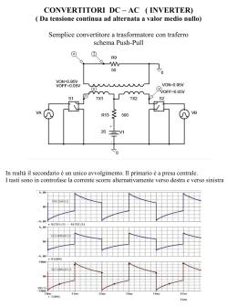
Inverter monofase
Inverter PWM
Inverter monofase
Inverter monofase a mezzo ponte
V0
i1
Vs/2
Q1
C1
D1
i0
Q1
Q2
‐Vs/2
T0
i2
R
Q2
Vs/2
Q1
i1
V0
Vs
Vs/2
D2
i2
C2
Caso di carico resistivo
Inverter PWM
Inverter monofase
Inverter monofase a mezzo ponte
Valore efficace tensione in uscita
V0
Q1
Q1
Q2
i1
V0 _ eff
2
=
T0
T0
⎡ T0
⎤
2
2
2
⎥
1 ⎢ 2 ⎛ Vs ⎞
⎛ Vs ⎞
⎢
=
dt + ∫ ⎜ − ⎟ dt ⎥ =
T0 ⎢ ∫ ⎜⎝ 2 ⎟⎠
2⎠
⎥
0
0⎝
⎢⎣
⎥⎦
T0
2
Vs2
Vs
dt
=
∫ 4
2
T0
i2
Caso di carico resistivo
0
Inverter PWM
Inverter monofase
Inverter monofase a mezzo ponte
Tensione istantanea in uscita
V0
a0 ∞
V0 =
+ ∑ ⎡ an cos ( nωt ) + bn sin ( nωt ) ⎤⎦
2 n =0 ⎣
Simmetria a un quarto d’onda dispari: an=0
0
π
⎡
⎤
0
2
⎢
⎥
Vs
Vs
2
bn = ⎢ ∫ − sin ( nωt ) d ( ωt ) + ∫ sin ( nωt ) d ( ωt ) ⎥ =
π⎢ π 2
2
⎥
0
−
⎢⎣ 2
⎥⎦
π⎫
⎧
0
2 Vs ⎪ ⎡ 1
1
⎤
⎡
⎤ 2 ⎪ 4 Vs
=
⎨ ⎢ cos nωt ⎥ π + ⎢ − cos nωt ⎥ ⎬ =
π 2 ⎪⎣ n
⎦−
⎣ n
⎦ 0 ⎪ nπ 2
2
⎩
⎭
V0 =
Q1
Q1
Q2
i1
T0
i2
Caso di carico resistivo
∞
⎡ 4 Vs
⎤
∑ ⎢⎣ nπ 2 sin ( nωt )⎥⎦
n =1,3,5
Inverter PWM
Inverter monofase
Inverter monofase a mezzo ponte
Tensione istantanea in uscita
V0 =
V0
∞
⎡ 4 Vs
⎤
sin
n
ω
t
(
)
⎢ nπ 2
⎥
⎣
⎦
n =1,3,5
∑
Q1
Q2
i1
per
Q1
T0
4 Vs 1
n = 1 ⇒ V01 =
= 0.45Vs
nπ 2 2
i2
Valore efficace della componente fondamentale
Caso di carico resistivo
Inverter PWM
Inverter monofase
Inverter monofase a mezzo ponte
V0
Caso ohmico‐induttivo
i0
i1
Vs/2
Q1
C1
D1
V0
Vs
L
i0
R
i2
Q2
Vs/2
C2
i1
T0
D2
D1
Q1
D2
Q2
Q1 ON
Q2 ON
Q2 OFF
Q1 OFF
D1
Inverter PWM
Inverter monofase
Inverter monofase a mezzo ponte
Tensione istantanea in uscita
V0
∞
i0
⎡ 4 Vs
⎤
V0 = ∑ ⎢
sin ( nωt ) ⎥
⎦
n=1,3,5 ⎣ nπ 2
i1
T0
Corrente a regime in uscita
i0 =
∞
∑
n =1,3,5 nπ
nωL
θn = a tan
R
2Vs
R 2 + ( nωL )
2
sin ( nωt − θn )
D1
Q1
D2
Q2
Q1 ON
Q2 ON
Q2 OFF
Q1 OFF
D1
Caso ohmico‐induttivo
Inverter PWM
Inverter monofase
Inverter monofase ponte
V0
Vs
Q1
D1
Q1Q2
D3
Q3
V0
Q1Q2
i0
Q3Q4
‐Vs
T0
Vs
L
Q4
D4
R
i0
Q2
E
D2
D1D2 Q1Q2
D3D4
Q3Q4
Inverter PWM
Inverter monofase
Inverter monofase ponte
Valore efficace tensione in uscita
V0
Vs
Q1Q2
Q3Q4
‐Vs
V0 _ eff
=
2
T0
T0
⎡ T0
⎤
2
⎥
1 ⎢2
2
2
⎢ ∫ (Vs ) dt + ∫ ( −Vs ) dt ⎥ =
=
T0 ⎢
⎥
0
0
⎢⎣
⎥⎦
Q1Q2
i0
T0
D1D2 Q1Q2
D3D4
Q3Q4
T0
2
2
V
s
∫ dt = Vs
0
Inverter PWM
Inverter monofase
Inverter monofase ponte
Tensione istantanea in uscita
a0 ∞
V0 =
+ ∑ ⎡ an cos ( nωt ) + bn sin ( nωt ) ⎤⎦
2 n =0 ⎣
Simmetria a un quarto d’onda dispari: an=0
0
π
⎡
⎤
0
2
⎢
⎥
Vs
Vs
2
bn = ⎢ ∫ − sin ( nωt ) d ( ωt ) + ∫ sin ( nωt ) d ( ωt ) ⎥ =
π⎢ π 2
2
⎥
0
−
⎢⎣ 2
⎥⎦
π⎫
⎧
0
2 ⎪⎡ 1
1
⎤
⎡
⎤ 2 ⎪ 4V
= Vs ⎨ ⎢ cos nωt ⎥ + ⎢ − cos nωt ⎥ ⎬ = s
π ⎪⎣ n
⎦− π ⎣ n
⎦ 0 ⎪ nπ
2
⎩
⎭
V0 =
V0
Vs
Q1Q2
Q1Q2
i0
Q3Q4
‐Vs
T0
D1D2 Q1Q2
D3D4
Q3Q4
∞
⎡4
⎤
∑ ⎢⎣ nπ Vs sin ( nωt )⎥⎦
n =1,3,5
Inverter PWM
Inverter monofase
Inverter monofase ponte
Tensione istantanea in uscita
V0 =
∞
⎡4
⎤
∑ ⎣⎢ nπ Vs sin ( nωt )⎦⎥
n =1,3,5
V0
Vs
Q1Q2
Q1Q2
i0
Q3Q4
‐Vs
T0
per
n = 1 ⇒ V01 =
4
1
Vs
= 0.9Vs
nπ
2
Valore efficace della componente fondamentale
D1D2 Q1Q2
D3D4
Q3Q4
Inverter PWM
Inverter monofase
Inverter monofase ponte
Tensione istantanea in uscita
V0 =
∞
⎡4
⎤
∑ ⎣⎢ nπ Vs sin ( nωt )⎦⎥
n =1,3,5
V0
Vs
Q1Q2
Q1Q2
i0
Q3Q4
‐Vs
T0
Corrente a regime in uscita
i0 =
∞
4Vs
∑
n =1,3,5 nπ
θn = a tan
R + ( nωL )
2
2
sin ( nωt − θn )
D1D2 Q1Q2
D3D4
Q3Q4
nωL
R
Inverter PWM
Scaricare