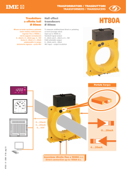
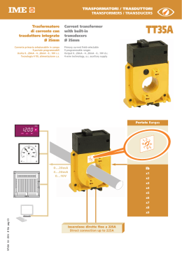
TRASFORMATORI / TRASDUTTORI
TRANSFORMERS / TRANSDUCERS
Trasduttore
a effetto hall
Ø 35mm
Misura corrente continua o pulsante
(valor medio) unidirezionale
Ingresso selezionabile in campo (10 portate)
Valori selezionabili: 10...100Acc
Uscita segnale normalizzato:
0...20mA opp. 4...20mA
Alimentazione ausiliaria HT35Bm:
20...60Vcc opp. 80...270Vca
Alimentazione ausiliaria HT35Bs:
15Vcc (derivata da HT35Bm)
Isolamento ingresso – uscita 4kV
Hall effect
transducer
Ø 35mm
HT35B
To measure unidirectional direct
or pulsating current (average value)
Field-selectable input (10 ranges)
Selectable ranges: 10...100Acc
Standard signal output:
0...20mA or 4...20mA
Auxiliary supply HT35Bm:
20...60Vdc or 80...270Vac
Auxiliary supply HT35Bs:
15Vdc (taken from HT35Bm)
Input – output insulation 4kV
HT35Bs
HT35Bm
Portate Ranges
A
A
200
100
0
1mA
NT763 07 - 2011 2a Ed. pag.1/4
482
1.5
✩
2
300
400
500
600
4...20mA
0...20mA
Ib
0=
1=
2=
3=
4=
5=
6=
7=
8=
9=
10A
20A
30A
40A
50A
60A
70A
80A
90A
100A
MODELLO
MODEL
AL. AUSILIARIA
AUX. AUSILIARY
HT1BM1017
80...270Vca/ac
HT1BM101C
20...60Vcc/dc
HT1BM1027
HT35Bm
80...270Vca/ac
HT1BM102C
20...60Vcc/dc
HT1BS101A
HT1BS102A
HT35Bs
15Vcc/dc
(derivata da /
taken from
HT35Bm)
USCITA
ANALOGICA
ANALOG
OUTPUT
USCITA 15Vcc
(per HT35Bs)
OUTPUT 15Vdc
(for HT35Bs)
INGRESSO
INPUT
0...20mA
max. 3 HT35Bs
4...20mA
10-20-30-40-50-60-70-80-90-100A
0...20mA
4...20mA
-
INGRESSO
INPUT
Corrente nominale In: selezionabile con commutatore
Current rating In: selectable by switch
Valori selezionabili In: 10 – 20 – 30 – 40 - 50 - 60 - 70 - 80 - 90 - 100A cc
Selectable values In: 10 – 20 – 30 – 40 - 50 - 60 - 70 - 80 - 90 -100A dc
Sovraccarico permanente: 1,2In
Continuous overland: 1,2In
CAMPO NOMINALE DI UTILIZZO
INPUT
Corrente continua o pulsante, unidirezionale
Unidirectional direct or pulsating current
Forma d’onda: corrente continua o pulsante
Waveform: direct or pulsating current
INTERVALLO DI MISURA
INPUT
Corrente: 0...In
Current: 0...In
USCITA
OUTPUT
Tipo: unidirezionale a zero vivo, per carico d’uscita variabile
Type: unidirectional, live zero for variable output load
Precisione (EN/IEC 60688): classe 1
Accuracy (EN/IEC 60688): class 1
Ondulazione (EN/IEC 60688): ≤ 2%
Ripple (EN/IEC 60688): ≤ 2%
Tempo di risposta (EN/IEC 60688): ≤ 300ms
Response time (EN/IEC 60688): ≤ 300ms
Valore nominale di corrente: 4...20mA - 0...20mA
Current rated value: 4...20mA - 0...20mA
Tensione disponibile: 10V
Compliance voltage: 10V
Carico di uscita: ≤ 500Ω
Output load: ≤ 500Ω
ALIMENTAZIONE AUSILIARIA
AUXILIARY SUPPLY
HT35Bm
HT35Bm
Valore nominale Uauxca: 80...270Vca
Rated value Uauxac: 80...270Vac
Frequenza nominale: 50Hz
Rated frequency: 50Hz
Frequenza di funzionamento: 47...63Hz
Working frequency: 47...63Hz
Autoconsumo: ≤ 1VA (4VA con collegamento a 3 HT35Bs)
Rated burden: ≤ 1VA (4VA con collegamento a 3 HT35Bs)
Valore nominale Uauxcc: 20...60Vcc
Rated value Uauxdc: 20...60Vdc
Autoconsumo: ≤ 1W (4W con collegamento a 3 HT35Bs)
Rated burden: ≤ 1W (4W con collegamento a 3 HT35Bs)
Protezione contro l’inversione di polarità
Protected against incorrect polarity
HT35Bs
HT35Bs
Valore nominale Uauxcc: 15Vcc
Rated value Uauxdc: 15Vdc
Autoconsumo: ≤ 1W
Rated burden: ≤ 1W
Alimentazione: derivata da HT35Bm
Supply: taken from HT35Bm
Ad ogni HT35Bm possono essere collegati fino a 3 HT35Bs
Each HT35Bm can supply up to 3 HT35Bs
ISOLAMENTO
(EN/IEC 61010-1)
INSULATION
Categoria di installazione: III
Installation category: III
Grado di inquinamento: 2
Pollution degree: 2
Tensione di riferimento per l’isolamento: 600V
Insulation reference voltage: 600V
Prova di tensione a impulso 6kV 1,2/50µs 0,5J
Impulse voltage test 6kV 1,2/50µs 0,5J
Circuiti considerati: ingresso, uscita,al. ausiliaria1
Considered circuits: input, output, aux. supply 1
Prova a tensione alternata 2kV valore efficace 50Hz/1min
A.C. voltage test 2kV r.m.s. 50Hz/1min
Circuiti considerati: uscita, al. ausiliaria1
Considered circuits: output, aux. supply 1
Prova a tensione alternata 4kV valore efficace 50Hz/1min
A.C. voltage test 4kV r.m.s. 50Hz/1min
Circuiti considerati: tutti i circuiti e massa
Considered circuits: all circuits and earth
1
solo per cod. HT35Bm
only for cod. HT35Bm
1
(EN/IEC 61010-1)
NT763 07 - 2011 2a Ed. pag.2/4
CODICI
ORDINAZIONE
ORDERING
CODE
COMPATIBILITÀ ELETTROMAGNETICA
ELECTROMAGNETIC COMPATIBILITY
Prove di emissione in accordo con EN/IEC 61326-1
Emission test according to EN/IEC 61326-1
Prove di immunità in accordo con EN/IEC 61326-1
Immunity test according to EN/IEC 61326-1
CONDIZIONI AMBIENTALI
ENVIRONMENTAL CONDITIONS
Gruppo di utilizzo: II
Usage group: II
Temperatura di riferimento: 15…30°C
Reference temperature: 15…30°C
Temperatura di impiego: -10…55°C
Nominal temperature range: -10…55°C
Temperatura di magazzinaggio: -25…70°C
Limit temperature range for storage: -25…70°C
Adatto all’utilizzo in clima tropicale
Suitable for tropical climates
Massima potenza dissipata : ≤ 4W
Max. power dissipation1: ≤ 4W
1
Per il dimensionamento termico dei quadri
For switchboard thermal calculation
1
1
CUSTODIA
HOUSING
Materiale custodia: policarbonato autoestinguente
Housing material: self-extinguishing polycarbonate
Connessioni: morsetti a vite, estraibili
Connections: removable screw terminals
Fissaggio: a vite
Mounting: screw type
Grado di protezione (EN/IEC 60529): IP20 morsetti
Protection degree (EN/IEC 60529): IP20 terminals
Peso: 160 grammi (HT35Bm) - 110 grammi (HT35Bs)
Weight: 160 grams (HT35Bm) - 110 grams (HT35Bs)
ESEMPI DI APPLICAZIONI
USE EXAMPLES
Aux. Supply
mA
(+) (–)
20 21
+
–
12 13 A
B
+
–
HT35Bm
+
mA
+
–
12 13
(–) (+) +
A B C
–
D
HT35Bs
+
mA
+
–
12 13
(–) (+) +
A B C
–
D
HT35Bs
+
NT763 07 - 2011 2a Ed. pag.3/4
mA
+
–
12 13
(–) (+) +
A B C
HT35Bs
+
–
D
12 13
+
DIMENSIONI
94
56 32
–
HT35Bs
AUX.
15Vdc
(–)
A
(+)
B
OUTPUT
x HT35Bs
HT35Bm
+
–
C
D
+
L
AUX.
SUPPLY
(+)
20
HT35Bs
56 32
(–)
21
OUTPUT
12 13
+
–
92
92
OUTPUT
x HT35Bs
+
–
A
B
+
L
DIMENSIONS
HT35Bm
La I.M.E. S.p.A. si riserva in qualsiasi momento, di modificare le caratteristiche tecniche senza darne preavviso. / I.M.E. S.p.A. reserves the right, to modify the technical characteristics without notice.
WIRING DIAGRAMS
NT763 07 - 2011 2a Ed. pag.4/4
OUTPUT
35
SCHEMI D’INSERZIONE
135
35
Scaricare