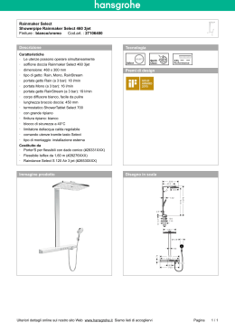
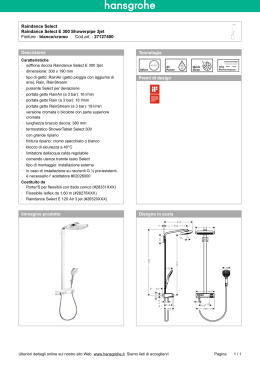
Binding Union STRUMENTI DI MISURA MICRO 94 TECHNICAL MANUAL A1 AL1 A2 HI AL2 LO PEAK HD TX HOLD MEASURE SELECT www.binding.it [email protected] RX RESET ENTER Technical Manual (MTU94xx-002-20081209.doc6) MICRO 94 SOMMARIO - SUMMARY INTRODUZIONE - INTRODUCTION ............................................................................................ 2 IDENTIFICAZIONE - IDENTIFICATION ....................................................................................... 4 CARATTERISTICHE - SPECIFICATIONS .................................................................................... 5 FUNZIONI - FUNCTIONS ............................................................................................................. 5 INSTALLAZIONE - INSTALLATION ............................................................................................. 6 CONNESSIONI - CONNECTIONS ............................................................................................... 7 MODO OPERATIVO - OPERATING MODE ................................................................................. 8 MODO PROGRAMMAZIONE - PROGRAMMING MODE............................................................. 9 SIGNIFICATO DELLE FUNZIONI - MEANING OF FUNCTION ................................................. 12 MODELLI - MODELS ................................................................................................................... 17 OPZIONI - OPTIONS.................................................................................................................. 26 BINDING UNION srl - via Cuorgnè, 21 - 10156 Torino - Italy - Tel. +39 - 011 - 2625414 - Fax +39 - 011 - 2625428 - E-mail [email protected] Technical Manual (MTU94xx-002-20081209.doc6) MICRO 94 INTRODUZIONE INTRODUCTION Vi ringraziamo per la scelta che avete effettuato acquistando la nostra apparecchiatura. Questo strumento è uno nell’ampia gamma di indicatori, trasmettitori e sistemi di misura da noi prodotti. Saremo lieti di inviarVi, se lo desiderate, il nostro “Catalogo Generale”. We thank you very much for purchasing our item. This instrument is one among the wide range of displays, transmitters and measuring devices of our production. If you wish to have more information, we will be glad to send you our “General Catalog”. Per usare correttamente questo prodotto e sfruttare al massimo le sue funzioni, Vi consigliamo di leggere attentamente questo manuale prima dell’utilizzo. Le soluzioni progettuali implementate nello strumento MICRO 94 permettono di offrire prestazioni adattabili alle molteplici esigenze dell' utilizzatore consentendogli l'uso in diversi campi di applicazione. Le principali caratteristiche dello strumento sono: • • • • • • • • • • • • • • • • • • • • • • • • • • • funzionamento a microprocessore HCMOS circuiti campionatori ad alta velocità autocalibrazione dei circuiti di acquisizione autozero dei comparatori di ingresso autodiagnosi delle funzioni interne circuiti di ingresso con banda passante programmabile tramite filtro di media digitale programmabilità tramite tastiera di tutte le funzioni operative protezione accesso alla programmazione possibilità di misurazione diretta dei segnali in ingresso (misurazione "sul campo") due soglie di allarme completamente configurabili due relè con relativi contatti associati agli allarmi visualizzazione dei picchi minimo e massimo di lettura configurazione delle opzioni tramite tastiera ritenzione dei dati in assenza di alimentazione tramite memoria non volatile (EEPROM) possibilità di interfacciamento a PLC possibilità di connessione a Personal Computer possibilità di collegamento a sistemi di acquisizione dati (Data Logger) possibilità funzione di Tara alimentazione standard 90...270 Vac switching interfaccia di comunicazione seriale isolata RS232D oppure RS485 (opzionale) possibilità di collegamento delle interfaccie seriali in sistema multiplo indirizzabile uscite BCD parallele optoisolate (opzionali) possibilità di configurazione delle uscite BCD in sistema multiplo indirizzabile uscite analogiche isolate 0...10 V / 0...20 mA / 2...10 V / 4...20 mA (opzionali) alimentazione ausiliaria per sensori e trasduttori possibilità di alimentazione isolata in bassa tensione 10...30 Vac (opzionale) possibilità di alimentazione isolata in continua 10...40 Vdc, 40...120 Vdc, 90...240 Vdc (opzionali) In order to use this product correctly and enjoy its full benefits, please read this instruction manual carefully before initial operations. Project solutions in instrument MICRO 94 offer performances fitting several requirements by users allowing use in different fields. Its main characteristics are: • • • • • • • • • • • • • • • • • • • • • • • • • • • HCMOS microprocessor based High-speed sampling circuits self-calibrating acquisition circuits autozero of input comparators self-test of internal functions programmable bandwidth on input achieved with digital everaging filter all operational functions programmable by means of the keyboard password protection for access to the programmable functions direct measurement capability of the input signals (i.e. “in-the-field” measurements) two completely configurable alarm thresholds two relays with dedicated contacts associated to the alarms display of max/min levels of the measured signal keyboard configurability of the options data storage in non-volatile memory (EEPROM) during power loss/removal PLC interface capability Personal Computer interface capability may be interfaced with external data acquisition equipments (e.g. Data Logger) tare function standard power supply 90...270 Vac switching electrically isolated RS232D or RS485 compatible serial port (optional) supports connection of the serial port to an individually addressable multi-drop system opto-isolated parallel BCD outputs (optional) supports connection of the BCD outputs in an individually addressable multi-drop system electrically isolated analog outputs 0-10 V, 0-20 mA, 2-10 V, 4-20 mA (optional) auxiliary power supply output for sensor and transducers may be powered from 10...30 Vac low voltage isolated supply (optional) may be powered from an isolated DC supply of 10...40 Vdc, 40...120 Vdc, 90...240 Vdc (optional) BINDING UNION srl - via Cuorgnè, 21 - 10156 Torino - Italy - Tel. +39 - 011 - 2625414 - Fax +39 - 011 - 2625428 - E-mail [email protected] 2 Technical Manual (MTU94xx-002-20081209.doc6) MICRO 94 Architettura interna dello strumento Instrument internal architecture La Figura 1 descrive l'architettura interna dello strumento e i blocchi circuitali che la compongono. I riquadri evidenziati da una linea tratteggiata indicano le possibili opzioni installabili nello strumento. Figure 1 illustrates the instrument’s internal architecture and highlights the individual circuit blocks contained in the unit. Dashed boxes indicate instrument’s optional circuitry. DISPLAY DISPLAY CONTROLLER INPUT MODULE ANNOUNCERS A1 INTEGRATOR & COMPARATOR A2 HI LO TX HD RX AMPLIFIER & FILTERING CONTACT 1 AUTOZERO RELAIS DRIVER SELF CALIBRATION CONTACT 2 CPU BUILT-IN TEST & SELF CALIBRATION EXTERNAL 24 Vdc RAM ROM EEPROM KEYBOARD RESET STANDARD POWER SUPPLY 90...270 Vac MAIN +V -V GROUND SYSTEM BUS BCD DATA OPTO COUPLERS ISOLATION POWER (+) (-) RS232 LEVEL TRANSLATOR GROUND Type 1 Drivers 0...10 V Output Drivers EXTERNAL 24 Vdc TYPE 2 Output 2...10 Vdc 0...20 mA GROUND 4...20 mA RX DRIVER TX SUPPLY RXR OPTIONAL INPUT 12 BIT D/A CONVERTER OPTIONAL ANALOG OUTPUT AUXILIARY 30mA CONTROLS OPTIONAL PARALLEL BCD INTERFACE ISOLATION 24V dc DRIVERS ISOLATED DC POWER SUPPLY I/O BUFFER +V -V TO/FROM REMOTE INSTRUMENT TXR OPTIONAL RS232 SERIAL INTERFACE GROUND ISOLATION OPTIONAL INPUT ISOLATED AC POWER SUPPLY 10...30V RS485 LEVEL TRANSLATOR +V -V GROUND DRIVER A TO NETWORK B I/O BUFFER OPTIONAL RS485 SERIAL INTERFACE BINDING UNION srl - via Cuorgnè, 21 - 10156 Torino - Italy - Tel. +39 - 011 - 2625414 - Fax +39 - 011 - 2625428 - E-mail [email protected] 3 Technical Manual (MTU94xx-002-20081209.doc6) MICRO 94 IDENTIFICATION IDENTIFICAZIONE B A1 A2 AL1 HI AL2 LO HD PEAK MEASURE Ogni indicatore ha una etichetta collegamenti (B) in poliestere metallizzato, isolata, autoestinguente, con stampa indelebile all’acqua, riportante i dati per l’identificazione del modello, l’alimentazione ausiliaria, il numero di matricola assegnato, il campo di misura, l’eventuale opzione interna e la descrizione dei morsetti disponibili. Inoltre in dotazione vengono fornite 15 etichette (A) complete di unità ingegneristiche. Code 9410, 12, 13, 14 9421, 22, 23, 24 9425 9426, 27, 28, 29 9433, 34, 35 9443, 44, 45 9447, 48, 49 9468 9470 9480 9482 9484 9485 Code S R H W Y Code 00 10 11 12 13 49 59 60 RX HOLD RESET SELECT ENTER A = Engineering unit labels L1 mA mV A V °C Hz %RH % W kW mbar bar INSTRUMENTS DC voltmeter AC voltmeter AC voltmeter (TV) TRMS AC voltmeter DC ammeter AC ammeter (CT) TRMS AC ammeter (CT) PT100 termometer Resistance meter Process meter 3 Wire potentiometer Strain gauge meter Frequency/Rate meter POWER Standard 90...270 Vac Optional 10...30 Vac Optional 10...40 Vdc Optional 40...120 Vdc Optional 90...240 Vdc TX kg/cm2 mmHg A Each indicator is supplied with a connection label (B) made of metallized polyester, nonconducting, self extinguishing, water resistant print, with the following data: model identification, auxiliary supply, serial number, range, internal options and description of available pins. Instrument is provided with 15 engineering unit labels (A) Range ±2, 20, 200,500V 2, 20, 200, 500V 100V 2, 20, 200, 500V 200, 2000mA, 60mV 200mA, 2A, 5A 200mA, 2A, 5A -100...+200, -200...+800°C 0.2, 2, 20, 200kΩ 0-5, 1-5, 0-10V/0-4-20mA 500Ω...50kΩ 0.5...3.5mV/V 20, 200, 2000, 20000Hz OPTIONS None Programmation Neutral execution Custom design Non standard engineering unit Remote HOLD function (BCD) Analog output 0-10V, 0-20/4-20mA Analog output 0-5V, 1-5V, 0-10mA Accuracy 0.05% 0.2% 0.3% 0.2...1% 0.2% 0.5% 0.5...1% 0.5% 0.2% 0.1% 0.1% 0.1% 0.2% Code 61 68 69 70 82 91 95 99 Excit. supply 24 Vdc 24 Vdc 24 Vdc 24 Vdc 24 Vdc 24 Vdc 24 Vdc --------24 Vdc 5Vdc 10 Vdc 5 Vdc (15 Vdc) OPTIONS Analog output ±5V, -3...+5V Optoisolated BCD output Optoisolated RS232 output Optoisolated RS485 output 15V auxiliary output (9485) Tropicalization Treatment Conformity certificate B.U.calibration certificate BINDING UNION srl - via Cuorgnè, 21 - 10156 Torino - Italy - Tel. +39 - 011 - 2625414 - Fax +39 - 011 - 2625428 - E-mail [email protected] 4 Technical Manual (MTU94xx-002-20081209.doc6) MICRO 94 SPECIFICATIONS CARATTERISTICHE Caratteristiche generali General specifications Tecnica di conversione : Integrazione doppia rampa Regolazione dello zero : automatica ad ogni ciclo CMRR : 86dB typ. Linearità : ± 1 LSB typ. Coefficiente di temperatura : 5ppm /°C (5-50°C) Banda passante : 15.9 Hz ± 10% Frequenza di campionamento : 12.5 Hz Tempo di conversione : 80 ms Aggiornamento lettura : da 1:1 a 100:1 Uscite allarmi a relè: max pot. Commut. 30W / 50VA max tens. commutabile 150Vdc / 230Vac max corrente commutabile 2A Isteresi allarmi : da 0 a 999 digit Ritardo allarmi : da 0 a 9 sec. Punti decimali : 5 Indicazione fuori scala : OFL / -OFL Impostazione parametri : tramite tastiera frontale Blocco della lettura : attivabile da tastiera Visualizzazione picchi : massimo e minimo Alimentazione sensori: vedi tabella pag. precedente voce excit supply Peso : 400grammi Grado protez. frontale : IP40 (IP65 con acc.AV0316) Categoria d’installazione : (cat. di sovratensioni) II Grado inquinamento : 2 (CEI EN61010-1) Conversion technique : dual slope integration Zero control : automatic every cycle CMRR : 86dB typ. Linearity : ± 1 LSB typ. Temperature coefficient : 5ppm/°C (5-50°C) Bandwidth : 15.9 Hz ± 10% Sampling frequency : 12.5 Hz Conversion time : 80 ms Reading update : from 1:1 to 100:1 Relay Alarms output : max switching power 30W /50VA max switching voltage 150Vdc / 230Vac max carrying current 2 A Alarms hysteresis : from 0 to 999 digit Alarms delay : from 0 to 9 sec. Decimal points : up to 5 Display Over range : OFL/-OFL Parameters programming : by keyboard Reading hold : by keyboard Peaks displaying : maximum and minimum Sensor power supply : see table on previous page ‘excit supply’ Weight : 400 grams Front protection : IP40 (IP65 with AV0316 accessory) Installation category : (overvoltage category) II Pollution degree : 2 (CEI EN61010-1) FUNZIONI FUNCTIONS ANNOUNCERS A1 A2 DIGIT 5 DECIMAL POINT AL 1 HI DIGIT 4 AL 2 PROGRAM MODE COMMANDS LO HD DIGIT 3 TX DIGIT 2 RX DIGIT 1 PEAK HOLD RESET MEASURE SELECT ENTER OPERATE MODE COMMANDS KEYBOARD Front panel The instrument front panel is illustrated in figure and shows the seven event announcers, five digits for data display and one keyboard consisting of five keys for the entry or change of operating parameters. Each key on the keyboard has a double function, which depends on the operating mode effective at the time of keypress. The functions indicated above the keys are effective when the instrument is in OPERATING MODE, while those below the keys are active in PROGRAMMING MODE according to following chart Pannello frontale In Fig. 3 è mostrato il pannello frontale dello strumento che include sette annunciatori di rispettivi eventi, cinque digit per la visualizzazione dei dati e una tastiera composta da cinque pulsanti per l'immissione o il controllo dei parametri operativi. Ogni pulsante della tastiera ha una doppia funzione ed assume un significato diverso in relazione al modo di funzionamento. Nel MODO OPE-RATIVO la tastiera agisce secondo le definizioni impresse al di sopra dei pulsanti ; nel MODO PROGRAM-MAZIONE, assume i significati delle diciture sottostanti. Annunciatori segnala l’ intervento dell’ allarme 1 segnala l’ intervento dell’ allarme 2 segnala il picco massimo di lettura segnala il picco minimo di lettura segnala il blocco della lettura annunciatore uscita seriale (opzione) annunciatore uscita seriale (opzione) A1 A2 HI LO HD TX RX Announcers announcer allarm 1 announcer allarm 2 announcer max peak announcer min peak announcer hold function announcer serial output (option) announcer serial output (option) BINDING UNION srl - via Cuorgnè, 21 - 10156 Torino - Italy - Tel. +39 - 011 - 2625414 - Fax +39 - 011 - 2625428 - E-mail [email protected] 5 Technical Manual (MTU94xx-002-20081209.doc6) MICRO 94 Display (digit) I display normalmente misurano il valore presente in ingresso espresso in unità ingegneristiche Altezza delle cifre 14.2mm Questo display visualizza il numero 1 e il segno negativo Se supera il fondo scala Se scende sotto l’inizio scala Punti decimali Se accesi indicano l’ inizio delle cifre decimali 5.4.3.2.1 5.4.3.2.1 5 OFL -OFL 5.4.3.2.1. Modo operativo Premendolo si visualizza il limite dell’allarme 1 Premendolo si visualizza il limite dell’allarme 2 Premendolo si visualizza alternativamente il picco massimo e minimo Premendolo si blocca la lettura Premendolo abbinato al tasto PEAK permette di resettare i picchi, se abbinato al tasto AL2 abilita la visualizzazione continua del valore di picco Modo programmazione Aumenta il valore della cifra selezionata (0...9) Seleziona la cifra da modificare tra i digit 5 4 3 2 1 Misura il valore in ingresso e lo acquisisce come inizio o fondo scala (InLo InHI) Seleziona la funzione desiderata Permette di entrare nella funzione selezionata AL1 AL2 PEAK HOLD RESET MEASURE SELECT ENTER Display Display normally shows the input actual value in engineering units. Characters height : 14.2 mm This display shows the number 1 and minus sign When end scale value is exceeded When bottom scale value is undergone Decimal points When lighted, show beginning of decimal figures Operating mode When pressed, alarm 1 limit is shown When pressed, alarm 2 limit is shown When pressed, max/min peak is alternatively shown When pressed, reading is held When pressed with the PEAK key, it allows to reset peaks; when pressed with the AL2 key, peak value will be continously displayed. Programming mode Increases the value of the selected digit (0..9) Selects the digit to be changed among the digits : 54321 Measures the input value and uses it as bottom or full scale value (InLo InHI ) It selects the needed function It allows to enter in the selected function INSTALLATION INSTALLAZIONE Dimensioni Fig.4 Spessore del pannello 1...8mm Dimensions Panel thickness 1...8mm 92 +0.5 96mm 5 107mm -0 B 48 C 44 45 +0.5 -0 A Montaggio dello strumento Mounting of the instrument Dopo la preparazione di un foro nel luogo d’installazione, l’indicatore viene inserito dalla parte frontale togliendo i cursori (C) che, riposizionati come in origine, serviranno per bloccare l’indicatore sul pannello. After practicing a hole in the place of installation, insert the instrument by front side removing the sliders (C) that can be used to hold the indicator on the panel itself. Precauzioni Warning Verificare che i valori di ingresso e di alimentazione presenti sulla “Etichetta collegamenti” corrispondano a quelli richiesti. Controllare che tensione e frequenza di alimentazione rientrino nelle tolleranze previste. E’ consigliabile inserire sempre dei fusibili di protezione sulla alimentazione. In fase di installazione separare il cablaggio da eventuali barre di potenza, relè, teleruttori, SCR, ecc. La verifica scrupolosa dello schema di inserzione è doverosa in quanto banali errori di collegamento possono danneggiare a volte irreparabilmente lo strumento . Check out that input values and power supply indicated in the “Wiring Label” correspond to the order. Check that main voltage and frequency lay within the tolerance boundaries. It is always advisable to insert protection fuse on the power supply. During installation never run the signal cables in the same conduit or raceway with AC power lines, conductors that feed motors, solenoids, SCR controls, that must be kept apart from relays, contactors, transformers and so on. It is advisable to check carefully the connection diagrams, because even banal connection faults may result in serious damages or may even destroy the instrument. BINDING UNION srl - via Cuorgnè, 21 - 10156 Torino - Italy - Tel. +39 - 011 - 2625414 - Fax +39 - 011 - 2625428 - E-mail [email protected] 6 Technical Manual (MTU94xx-002-20081209.doc6) MICRO 94 CONNESSIONI CONNECTIONS Alimentazioni Power supply L’alimentazione alternata (codice S-K) si collega ai morsetti 11 (GND), 12 (L), 13 (N). L’alimentazione in continua (codice K-W-Y) si collega ai morsetti 11 (GND) 12 (+) 13 (-). Lo strumento utilizza alimentatori switching ad alta-frequenza con ingresso a range esteso. Al fine di garantire i livelli di disturbo previsti dalle attuali norme CE relative alla compatibilità elettromagnetica, si raccomanda di collegare il morsetto di massa dello strumento ( morsetto n° 11) ad una efficace presa d i terra. AC power supply (code S-K) has to be connected to terminal boards 11(GND), 12 (L), 13 (N). DC power supply (code K-W-Y) has to be connected to terminal boards 11(GND), 12 (+), 13 (-). The instrument is powered by a high frequency switching power supply with universal input. To guarantee the EMC requirements of European Standard CE, we recommend to connect the instrument ground terminal (terminal board n° 11) to an effective earth. Alimentazione standard (S) : 90...270 Vac 50....60Hz Potenza assorbita : ≤ 4 VA Rigidità dielettrica : ≥ 2300 Vac 50 Hz Resistenza isolamento : ≥ 100 Mohm Standard power supply (S) : 90...270 Vac 50....60Hz Power : ≤ 4 VA Dielectrical strength : ≥ 2300 Vac 50 Hz Insulation resistance : ≥ 100 Mohm Alimentazione opzionale (K): 10...30 Vac/ 10...40 Vdc Potenza assorbita : ≤ 4VA / ≤ 3 W Corrente di spunto : ≤ 1.5A Rigidità dielettrica : ≥ 500 Vac Resistenza di isolamento : ≥ 100 MΩ Optional power supply (K) : 10...30 Vac / 10...40 Vdc Power : ≤ 4VA / ≤ 3 W Inrush current : ≤ 1.5A Dielectrical strength : ≥ 500 Vac Insulation resistance : ≥ 100 MΩ Alimentazione opzionale (W) : 40....120 Vdc Potenza assorbita :≤3W Corrente di spunto : ≤ 1.5A Rigidità dielettrica : ≥ 500 Vac Resistenza di isolamento : ≥ 100 MΩ Alimentazione opzionale (Y) : 90....240 Vdc Potenza assorbita :≤3W Corrente di spunto : ≤ 1.5A Rigidità dielettrica : ≥ 500 Vac Resistenza di isolamento : ≥ 100 MΩ Optional power supply (W) : 40....120 Vdc Power :≤3W Inrush current : ≤ 1.5A Dielectrical strength : ≥ 500 Vac Insulation resistance : ≥ 100 MΩ Optional power supply (Y) : 90....240 Vdc Power :≤3W Inrush current : ≤ 1.5A Dielectrical strength : ≥ 500 Vac Insulation resistance : ≥ 100 MΩ Connessioni elettriche Electrical connections La Figura mostra le morsettiere posteriorI dello strumento e le connessioni comuni a tutta la linea Micro 94. La funzione dei morsetti d’ingresso 1÷4 (INPUT) e del connettore superiore è illustrata nella pagina specifica del modello e delle opzioni (pag. 17 e seguenti). Sui morsetti 9 e 10 (Vexc.) è disponibile l’uscita dell’alimentazione ausiliaria per sensori esterni (sui modelli che la prevedono come indicato a pagina 4). I morsetti 5 - 6 e 7 - 8 sono i contatti degli allarmi 1 e 2. Figure shows electrical connections on the back side of the instrument and the connections common for Micro 94 line instruments. The functions of INPUT terminal boards and upper connector are explained in the specific page of the model and of the options (page 17 and following). On clamps 9 and 10 is available an auxiliary power supply output for external sensors (on the models provided for) as shown at page 4. Clamps 5-6 and 7-8 represent alarm 1 and 2 contacts. N.B. Quando è presente l’opzione 49 o 49A, il contatto dell’allarme due non è presente. Con l’opzione 49A si blocca la lettura (hold) cortocircuitando i morsetti 5 e 6 Con l’opzione 49 si blocca la lettura fornendo un segnale come indicato nello schema di destra. NOTICE: With option 49 and 49A contact alarm set point 2 is excluded. with option 49A clamps 5 and 6 enable HOLD function if short- circuited. with option 49 clamps 5 and 6 enable HOLD function if supplied a signal as indicated : 5...24Vdc 10mA max PROGRAMMING 6 INPUT 2 1 RELAIS V exc.(-) V exc.(+) 1 2 3 4 5 6 7 8 9 10 11 12 13 N POWER L 5 GND BINDING UNION srl - via Cuorgnè, 21 - 10156 Torino - Italy - Tel. +39 - 011 - 2625414 - Fax +39 - 011 - 2625428 - E-mail [email protected] 7 Technical Manual (MTU94xx-002-20081209.doc6) MICRO 94 MODO OPERATIVO OPERATING MODE Autodiagnosi Self test All’accensione lo strumento esegue automaticamente l’autodiagnosi a l’autocalibrazione. Questa fase dura circa 1 secondo e viene rappresentata sul display dal messaggio “SELF”. Se il test di calibrazione viene superato positivamente lo strumento entrerà nel “MODO OPERATIVO” ed inizierà a visualizzare i valori acquisiti. Diversamente l’indicazione “SELF” rimarrà visualizzata in modo permanente indicando un guasto. Once powered, the instrument automatically performs self test and autocalibration. This phase lasts about one second and its result is shown on the display by the message “SELF”. If self test is okay the instrument enters the “OPERATING MODE” showing the acquired values. On the contrary, if the message “SELF” is continuously displayed, a failure is occurring. Modo operativo Operating mode Nel modo operativo lo strumento esegue la misura della grandezza fisica in ingresso secondo le predisposizioni programmate dall’utente. Tuttavia sono possibili alcune operazioni di verifica e controllo agendo sulla tastiera del pannello frontale. In operating mode the instrument performs the measurement of the input value according to user’s settings. Nevertheless, it is possible to make some controls simply using the front panel keyboard. a) Verifica soglia Allarme 1. Alla pressione del pulsante “AL1” il display presenterà il valore di soglia impostato per l’allarme 1. Al rilascio del pulsante verrà ripristinato il valore della grandezza in ingresso. b) Verifica soglia Allarme 2. Come sopra ma premendo “AL2”. c) Lettura dei valori di picco minimo e massimo. Il pulsante “PEAK” permette la visualizzazione ciclica di entrambi i valori. Premendo una prima volta il pulsante “PEAK” si accenderà l’annunciatore “Hi” indicando che la lettura si riferisce al valore massimo. Rilasciando il pulsante verrà ripristinato il valore della grandezza in ingresso. Premendo una seconda volta il pulsante “PEAK” si accenderà l’annunciatore “Lo” e sul display verrà visualizzato il valore di picco minimo. N.B. Premendo contemporaneamente i pulsanti “RESET” e “AL2” si otterrà la visualizzazione continua del valore di picco massimo sul display (segnalata dall’accensione dell’annunciatore “HI”), premendoli una seconda volta si visualizzerà il valore del picco minimo (accensione annunciatore “LO”). Quando è abilitata questa funzione i pulsanti frontali non sono operativi se non per tornare al modo programmazione. Per tornare al funzionamento normale senza perdere i valori di picco è sufficiente entrare ed uscire dalla programmazione. d) Azzeramento dei valori di picco. L’azzeramento dei valori di picco avviene mantenendo premuto il tasto “RESET” e premendo il tasto “PEAK”. e) Sospensione aggiornamento display (Hold). Premendo il tasto “HOLD” si accende l’annunciatore “HD” e si sospende l’aggiornamento del display. Il pulsante “HOLD” e di tipo bistabile cioè ad una prima pressione sospende l’aggiornamento, mentre ad una successiva pressione lo ripristina. f) Segnalazione superamento soglie di allarme. I due annunciatori “A1” e “A2” relativi agli allarmi 1 e 2 indicano ,quando accesi, che la corrispondente soglia e’ stata superata. a) Alarm 1 threshold check. By pressing “AL1” key the display shows the threshold setting for alarm 1. If the key is depressed the display shows again the normal input value. b) Alarm 2 threshold check. As for alarm 1 but pressing “AL2”. c) Maximum and Minimum Peak. “PEAK” key allow the cyclic reading of both minimum and maximum peak values. If “PEAK” key is pressed once the “Hi” announcer turns on, meaning that the display refers to the maximum peak value. By depressing “PEAK” key the display shows again the normal input value. If “PEAK” key is pressed a second time the “Lo” announcer turns on, the display will show the minimum peak value. NOTICE Maximum peak value is continuously displayed by pressing “RESET” and “AL2” together (announcer “HI” is on), while minimum peak value is continuously displayed by pressing together the same keys a second time (announcer “LO” is on ). When this function is enabled, front keys are not available but for going back to the programming mode. Normal operating mode without losing peak values is achievable by making a programming cycle. d) Peak value reset. Peak value reset is performed by holding “RESET” key on and by pressing “PEAK” key. e) Display hold. If “HOLD” key is pressed the announcer “HD” turns on and the display updating is stopped. ”HOLD” key is a bistable type that performs the hold function at the first pressing while allows the display updating at the second pressing. f) Alarm over threshold . Announcers “A1” and “A2” represent the status of the alarms 1 and 2 and show, when they are on, that the corresponding threshold has been overcome. BINDING UNION srl - via Cuorgnè, 21 - 10156 Torino - Italy - Tel. +39 - 011 - 2625414 - Fax +39 - 011 - 2625428 - E-mail [email protected] 8 Technical Manual (MTU94xx-002-20081209.doc6) MICRO 94 MODO PROGRAMMAZIONE PROGRAMMING MODE Per modificare le predisposizioni interne dello strumento e’ necessario entrare nel modo programmazione. Tale operazione si effettua mantenendo premuto il tasto “RESET” e premendo il tasto “HOLD”. A questo punto sul display comparirà la richiesta di password con il messaggio “PASS”. Rilasciando i pulsanti “HOLD“ e “RESET” il display presenterà la password di default “ - - - - ” ed aspetterà l'immissione, tramite i pulsanti e , della password definita dall'utilizzatore. Se non era stata inserita una password dall'utente è sufficiente passare alla voce successiva usando il tasto “SELECT”. Per inserire una password, quando lo strumento visualizza la scritta "HPASS" premere "ENTER" ricomparirà “ - - - -” tramite i pulsanti e inserire la nuova password. Il funzionamento dei tasti e segue le regole del “ROLLING MODE”. Se la password e’ corretta, la successiva pressione del pulsante “SELECT” permetterà di accedere alle funzioni interne dello strumento, diversamente comparirà il messaggio “FAIL” e dopo circa un secondo lo strumento ritornerà nel modo operativo. To modify instrument internal settings it is necessary to enter programming mode. This operation is performed by holding “RESET” key on and by pressing “HOLD” key. At this time the display shows the password request with the message “PASS”. By depressing “HOLD” and “RESET” keys the default password “ - - - - ” is displayed and the instrument waits the user’s password to be entered by means of and keys. If a defined password is not present this entering can be avoided by pressing the “SELECT” key. To enter a password when the instrument displays “HPASS” press the “ENTER” key and the display will show “ - - - -” again. The operation of these keys ( and ) is according to the “ROLLING MODE” rule. If the password is right, the following pressing of “SELECT” key allows the user to access to the internal function settings of the instrument, otherwise a “FAIL” message is displayed and after about a second the instrument goes back to the operating mode. a) Implementazione delle funzioni interne. Le funzioni interne vengono selezionate col pulsante “SELECT”. Sul display compariranno i nomi delle funzioni interne nell’ordine riportato nella “PROGRAMMING TABLE”. b) Modifica dei parametri. Per modificare uno specifico parametro di una funzione e’ necessario selezionare la funzione con il tasto “SELECT” ed attivare il programma di modifica tramite il tasto “ENTER”. In questo modo il display indicherà il parametro associato alla funzione. Se il parametro e’ predeterminato sarà modificabile agendo sul pulsante mentre se e’ selezionabile sarà modificabile tramite i pulsanti e e potrà assumere qualsiasi valore numerico. c) Memorizzazione dei parametri. La memorizzazione del parametro modificato avviene con la pressione del tasto “SELECT” .Tale operazione determinerà inoltre il posizionamento del display sul nome della funzione successiva. Se il valore del parametro modificato non e’ coerente verrà ripristinato il valore precedente. Se non si desidera modificare il parametro di una determinata funzione e’ sufficiente premere il pulsante “SELECT” senza agire sui pulsanti e d) Uscita dal modo programmazione. Per ritornare al modo operativo e’ necessario mantenere premuto il tasto “ENTER” e premere il tasto “SELECT”. In questo modo sul display comparirà il messaggio “SAVE” per indicare che i parametri modificati sono stati salvati. a) Internal functions implementation. Internal functions are selectable operating on “SELECT” key. The display shows internal function names according to the order shown in the “PROGRAMMING TABLE”. b) Parameter adjustment. To adjust a function’s specific parameter it is necessary to select the function by means of the “SELECT” key and to initiate the modifying program by operating the “ENTER” key. In this way the display shows the parameter value associated to the function. If the parameter is prefixed it is adjustable by using key. If the parameter is of a selectable type, it is adjustable by means of and keys and it may be any numerical value selected by the user. c) Parameter saving. To save the modified parameter it is necessary to operate on the “SELECT” key. As a result of this operation the display shows the name of the following function. If the modified parameter value is not coherent with the limit of the function, the previous value is shown. To avoid the saving of a modified parameter it is necessary to operate on the “SELECT” key without using and keys. d) Quit programming mode. To quit programming mode and return to operating mode hold “ENTER” key on and press “SELECT” key. In this way the display shows the message “SAVE” to indicate that all modified parameters have been saved in the instrument memory. BINDING UNION srl - via Cuorgnè, 21 - 10156 Torino - Italy - Tel. +39 - 011 - 2625414 - Fax +39 - 011 - 2625428 - E-mail [email protected] 9 Technical Manual (MTU94xx-002-20081209.doc6) MICRO 94 PROGRAMMING TABLE SELECT HPAS SELECT rAr ENTER SELECT ISEL ENTER ENTER ---- NEW VALUE YES 0000 SELECT SELECT NEW VALUE In 3 SELECT 1.9999 MEASURE SELECT SELECT ENTER SELECT 1.9999 MEASURE SELECT SELECT dIHI ENTER SELECT 0000 In 2 SELECT dILo ENTER SELECT SELECT no SELECT InHi ENTER SELECT SELECT SELECT InLo SELECT SELECT NEW VALUE NEW VALUE NEW VALUE SELECT SELECT In 1 dECP ENTER SELECT Con1 SELECT HYS1 ENTER SELECT ENTER SELECT 0 1.9999 SELECT NEW VALUE SELECT NEW VALUE SELECT SELECT Con2 YES SELECT dLY2 ENTER SELECT no SELECT SELECT SELECT ENTER SELECT 00 SELECT SELECT NEW VALUE YES Addr SELECT 0 SELECT NEW VALUE 5 ENTER SELECT 000 dn SELECT NEW VALUE ENTER SELECT UP no SELECT HYS2 SELECT 00 NEW VALUE ENTER SELECT ENTER SELECT 1.9999 SELECT 0 AVEr ENTER SELECT SELECT POL2 SELECT UPdn ENTER dn ENTER SELECT AL1 UP SELECT AL2 SELECT SELECT NEW VALUE SELECT SELECT ENTER 000 YES dLY1 POL1 SELECT no SELECT SELECT ENTER SELECT SELECT SELECT SELECT NEW VALUE SPEd ENTER SELECT SELECT OSEL SELECT ENTER WRONG PASSWORD SELECT SELECT BACK TO OPERATING MODE SoLc 0000 Adch 0000 SELECT no SELECT NEW VALUE 75 ENTER SELECT SELECT NEW VALUE SELECT ENTER SELECT SELECT An2 SELECT ENTER SELECT An1 FAIL EoLc SELECT YES BINDING UNION srl - via Cuorgnè, 21 - 10156 Torino - Italy - Tel. +39 - 011 - 2625414 - Fax +39 - 011 - 2625428 - E-mail [email protected] 9600 10 Technical Manual (MTU94xx-002-20081209.doc6) MICRO 94 Valori iniziali Initial (default) value Le tabelle indicano i valori programmati internamente quando lo strumento esce dalla fabbrica. La colonna "DISPLAY" si riferisce al messaggio indicato dallo strumento quando si agisce sul pulsante SELECT durante la fase di PROGRAMMAZIONE. La colonna "VALUE" indica il dato mostrato sul display alla pressione del pulsante ENTER. The tables indicate the default (factory preset) values of the instrument’s internal parameters. In the tables, the column “DISPLAY” refers to the message displayed by the instrument when the “SELECT” key is pressed in PROGRAM Mode. The column “VALUE” shows the data that is displayed when the “ENTER” key is pressed. FUNZIONE Password Tara Selezione tipo di ingresso Valore minimo di ingresso Valore massimo di ingresso Valore minimo sul display Valore massimo sul display Posizione punto decimale Filtro di media Aggiornamento lettura Soglia allarme 1 Polarità allarme 1 Isteresi allarme 1 Attivazione relè 1 Ritardo intervento relè 1 Soglia allarme 2 Polarità allarme 2 Isteresi allarme 2 Attivazione relè 2 Ritardo intervento relè 2 Indirizzo RS232D o BCD Velocità RS232D Inserimento caratteri RS232D Caratteri di inizio stringa Caratteri di fine stringa Selezione uscita analogica VALUE ---no 2 0000 19999 0000 19999 5 no 00 19999 UP 000 no 0 19999 UP 000 no 0 00 9600 no 00Hek 00Hek 1 DISPLAY HPASS rAr ISEL InLo InHI dILo dIHI dECP AVEr Updn AL1 POL1 HYS1 Con1 dLY1 AL2 POL2 HYS2 Con2 dLY2 Addr SPEd Adch SoLc EoLc OSEL FUNCTION Password Tare Input selection Minimum input level Maximum input level Display minimum value Display maximum value Decimal point position Average filter Reading updating Alarm 1 threshold Alarm 1 polarity Alarm 1 hysteresis Relay 1 enable Relay 1 delay Alarm 2 threshold Alarm 2 polarity Alarm 2 hysteresis Relay 2 enable Relay 2 delay RS232D or BCD address RS232D speed RS232D characters insertion Head characters Tail characters Analog output selection Errori di impostazione Set-up Errors La seguente tabella indica i codici di errore mostrati sul display dello strumento in corrispondenza delle funzioni associate quando un parametro impostato durante la fase di programmazione non è coerente con i limiti della funzione stessa (parametro fuori limiti consentiti). I codici di errore vengono visualizzati per 1 secondo, tempo sufficiente all'operatore per riconoscere il tipo di impostazione errata commessa durante la programmazione. Al termine della segnalazione verrà ripristinato il valore precedente all'operazione che ha generato la condizione di errore. The table below defines the error codes which may be displayed during data input and shows the function associated to that error code. The error code will be displayed in “PROGRAM Mode” if an input parameter is not compatible with the range of values allowed for that function (parameter out of range). The error codes are displayed for 1 second, time enough to allow the operator to recognize the type of input error that occurred. At the end of the signal, the previous parameter value will be recalled and displayed, the wrong value will be cancelled. CODICI DI ERRORE Ingresso minimo ≥ ingresso massimo Ingresso massimo ≤ ingresso minimo Display minimo ≥ display massimo Display massimo ≤ display minimo Soglia allarme 1 fuori scala Polarità allarme 1 fuori scala Isteresi allarme 1 fuori scala Soglia allarme 2 fuori scala Polarità allarme 2 fuori scala Isteresi allarme 2 fuori scala Indirizzo > 63 Errore checksum in lettura Errore verifica dopo scrittura Errore funzionale DISPLAY E=03 E=04 E=05 E=06 E=10 E=11 E=12 E=15 E=16 E=17 E=20 E=97 E=98 E=99 ERROR CODES Minimum input ≥ maximum input Maximum input ≤ minimum input Display minimum ≥ display maximum Display maximum ≤ display minimum Alarm 1 threshold out of range Alarm 1 polarity out of range Alarm 1 hysteresis out of range Alarm 2 threshold out of range Alarm 2 polarity out of range Alarm 2 Hysteresis out of range Address > 63 Checksum error during reading Memory error after writing Functional error BINDING UNION srl - via Cuorgnè, 21 - 10156 Torino - Italy - Tel. +39 - 011 - 2625414 - Fax +39 - 011 - 2625428 - E-mail [email protected] 11 Technical Manual (MTU94xx-002-20081209.doc6) MICRO 94 SIGNIFICATO DELLE FUNZIONI Le seguenti voci descrivono i significati delle diciture presenti nelle tabelle riassuntive delle funzioni: FUNCTIONS MEANING The following definitions apply to the terminology used in the function summary tables below : 1. Significato acronimo - Tutte le funzioni vengono rappresentate sul display dello strumento in forma siglata (acronimo). A destra di questo campo viene indicata la dicitura completa dell'acronimo. 1. Acronym meaning - all function names are displayed in shortened form (acronym). In the first field is shown the complete definition of the acronym. 2. Scopo della funzione - Questo campo descrive lo scopo della funzione dettagliando, quando necessario, tutte le operazioni che l'utilizzatore deve compiere per programmare la funzione stessa secondo i valori desiderati. 3. Pulsanti attivi - Durante il modo PROGRAMMAZIONE vengono attivati solamente i pulsanti necessari alla modifica della funzione. Questo campo indica, i pulsanti attivi. I pulsanti rimanenti non indicati nel campo, anche se premuti, non hanno alcun effetto. 4. Tipo dato inseribile - Nello strumento sono inseribili due tipi di dati : valori selezionabili da utente o predeterminati dal programma. Questo campo indica se l'attuale funzione consente l'immissione di valori selezionabili o esclusivamente di valori predeterminati. 5. Digit attivi - Durante la programmazione i digit dello strumento vengono attivati in modo differente in relazione alla funzione selezionata. Questo campo indica quali digit possono essere attivi (accesi) durante la programmazione della funzione in corso. 6. Possibili valori digit - Durante la programmazione, i digit possono assumere valori diversi in relazione alla funzione selezionata. Il campo indica, in corrispondenza dei digit attivi, i valori che possono assumere i digit stessi. 7. Possibili diciture display - In funzioni con immissione a parametri predeterminati la definizione del valore desiderato si ottiene selezionando la dicitura che viene presentata sul display dello strumento. Questo campo elenca tutti i possibili messaggi che compariranno durante la programmazione dell'attuale funzione. 8. Significato diciture display - Questo campo descrive il significato delle diciture presentate sul display quando si selezionano funzioni aventi parametri ad ingresso predeterminato. 9. Significato digit 1 - In alcune funzioni il valore immesso non ha un significato diretto ma si avvale di un numero, indicato dal digit 1, per selezionare una tipologia di funzionamento. Questo campo descrive la tipologia di funzionamento associata al numero selezionato su tale digit. N.B. Le funzioni InLo, InHI, DiLo, DiHi servono per il cambio delle tarature dello strumento. Il loro uso, quando necessario, è precisato alla pagina relativa al singolo modello. In ogni altro caso vanno solo usate per esigenze particolari. 2. Function’ purpose - the second field describes the purpose of function giving details, where necessary, of all the operations to be performed in order to program the function as desired. 3. Active keys - In PROGRAM mode only the keys necessary for programming are active. This field indicates which keys are active. The remaining keys not indicated in this field , even if pressed, do not effect the programming of the requested function. 4. Data type to input - Two types of data can be normally entered. They can be defined to the desired user’s value or predefined by the program. This field indicates if the function allows entering of selectable data or only preset data. 5. Active digits - during programming different digits become active according to the selected function. This field indicates which display digits can be active (lighted) during the function programming. 6. Possible digit values - during function programming, each single display digit will take on different values depending on the selected function. The field indicates, for each active digit, the range it can take on. 7. Possible display messages - in some functions where user must enter prefixed parameters, the selection is made by scrolling until the desired choice appears on the display and by confirming it.This field indicates all possible messages which may be displayed during the function programming. 8. .Meaning of displayed messages - this field describes the meaning of each of the possible displayed messages for the selected predefined parameter functions only. 9. Meaning of digit 1 - in some functions the entered value represents a predefined parameter choice, which selects the type of operation required from the instrument. This field defines the predefined choices associated to each numeric value displayed at the DIGIT 1 position. NOTICE The functions InLo, InHI, DiLo, DiHi are used to modify instrument calibration. Their use, when needed, is explained on the page corresponding to the concerned instrument model. Otherwise, use them only when it is really necessary. BINDING UNION srl - via Cuorgnè, 21 - 10156 Torino - Italy - Tel. +39 - 011 - 2625414 - Fax +39 - 011 - 2625428 - E-mail [email protected] 12 Technical Manual (MTU94xx-002-20081209.doc6) MICRO 94 HPAS Password - Valore di default (- - - -). Se si inseriscono dei simboli diversi da quelli di default l’ingresso al Modo Programmazione viene impedito finchè non si inserisce l’esatta Password. Pulsanti attivi: SELECT ENTER Tipo dato inseribile: Parametro ad ingresso selezionabile Digit attivi: || || Digit 4 || Digit 3 || Digit 2 || Digit 1| Possibili valori digit: Qualsiasi combinazione dei caratteri: 0 1 2 3 4 5 6 7 8 9 A b C d E F blank c H h J L n o P r U u Y - = O Password - Default value (- - - -). If symbols other than those of Default are inserted, input to the programming mode is inhibited, as long as the correct password is not introduced. Active keys: SELECT ENTER Type of insertable data: Parameter with selectable input Active digits: || || Digit 4 || Digit 3 || Digit 2 || Digit 1| Possible digit values: Every character mix : 0 1 2 3 4 5 6 7 8 9 A b C d E F blank c H h J L n o P r U u Y - = O rAr Tara - Valore di default - no Se abilitata (yes) permette nel normale funzionamento (modo operativo) di azzerare il segnale presente agli ingressi premendo i pulsanti RESET e AL1. Questa funzione non influisce sui valori di taratura impostati, comportandosi quindi come una vera Tara. La funzione è attivabile solo con InLo = 0000, per esigenze diverse contattare il nostro servizio tecnico. Pulsanti attivi: AL1 RESET Tipo dato inseribile: Parametro ad ingresso predeterminato Digit attivi: || || Digit 4 || Digit 3 || Digit 2 || || Possibili diciture display: yes no Significato diciture: yes = tara inserita no = tara disinserita Tare - Default value - no When activated (yes), it allows in normal operation (operating mode) to set to zero the input signal by pressing the keys RESET and AL1. This function does not influence the preset tare value, and therefore behaves as a real tare. Function is selectable only if InLo = 0000. For different application please contact our technical support. Active Keys: AL1 RESET Type of insertable data: Parameter with preset input Active digits: || || Digit 4 || Digit 3 || Digit 2 || || Possible display text: yes no Text meaning: yes = inserted tare no = disinserted tare ISEL Selezione del tipo di segnale in ingresso - Valore di default 2 Scopo della funzione - Effettua l'adattamento dei circuiti di ingresso dello strumento al tipo di segnale ad esso collegato. Durante l'operazione di selezione, il messaggio "In" appare sul display assiema all'unico digit attivo (digit 1) per indicare che si sta operando una scelta sul tipo di segnale in ingresso. Nei modelli in cui questa funzione è attiva, esiste una descrizione dettagliata. Pulsanti attivi SELECT ENTER Tipo dato inseribile - Parametro ad ingresso predeterminato Digit attivi || || Digit 4 || Digit 3 || || Digit 1 || Possibili diciture display - || I || n || || 1 2 3 || Significato digit1 1, 2, 3 = dipende dall’ingresso Input Signal type Selection - Default value 2 Function aim : it adapts the instrument input circuits to the connected type of signal. During selection, message “In” appears on the display as well as the only active digit ( digit 1 ), to show that input signal type selection is running. For the models where this function is enabled you will find a detailed information. Active keys SELECT ENTER Insertable type of data - Parameter with preset input Active digits - || || Digit 4 || Digit 3 || || Digit 1 || Possible Display text : - || I || n || || 1 2 3 || Meaning of digit 1 1, 2, 3 = depending on input InLo Valore minimo del segnale in ingresso - Valore di default: 0000 Può essere molto utile nel caso in cui il segnale derivante da sensori non sia esattamente a zero, in tal caso con segnale minimo applicato, entrare nella funzione e premere il pulsante MEASURE, lo strumento misurerà il valore presente ai suoi ingressi e lo acquisirà come valore di zero. Pulsanti attivi: MEASURE SELECT ENTER Tipo dato inseribile: Parametro ad ingresso selezionabile Digit attivi: || Digit 5 || Digit 4 || Digit 3 || Digit 2 || Digit 1 || Possibili valori digit: qualsiasi combinazione0-1-2-3-4-5-6-7-8-9 Min. Input Signal value - Default value : 0000 It can be really useful when the signal coming from sensors is not exactly zero. Then with min. signal applied, enter the function and press the key MEASURE, the instrument will measure the real value at its input and will handle it as zero value. Active Keys: MEASURE SELECT ENTER Type of insertable data: Parameter with selectable input Active digits: || Digit 5 || Digit 4 || Digit 3 || Digit 2 || Digit 1| Possible digit values:Every character mix 0 1 2 3 4 5 6 7 8 9 InHI Valore massimo del segnale in ingresso - Valore default: 19999 Normalmente corrisponde al fondo scala dello strumento 19999. Si possono compensare eventuali errori con il tasto MEASURE, il funzionamento è uguale alla voce InLo ma con segnale massimo applicato agli ingressi. Pulsanti attivi: MEASURE SELECT ENTER Tipo dato inseribile: Parametro ad ingresso selezionabile Digit attivi: || Digit 5 || Digit 4 || Digit 3 || Digit 2 || Digit 1 || Possibili valori digit:qualsiasi combinazione 0-1-2-3-4-5-6-7-8-9 Min. Input Signal value - Default value : 19999 It normally corresponds to the instrument full range 19999 With the key MEASURE possible errors can be offset. The operation is the same as at position InLo, but with max signal applied to the inputs. Active keys: MEASURE SELECT ENTER Type of insertable data: Parameter with selectable input Active digits: || Digit 5 || Digit 4 || Digit 3 || Digit 2 || Digit 1| Possible digit values:Every character mix 0 1 2 3 4 5 6 7 8 9 dILo Valore minimo del dato sul display - Valore di default: 0000 Da utilizzare quando lo strumento deve visualizzare un valore minimo diverso da quello in ingresso. Pulsanti attivi: SELECT ENTER Tipo dato inseribile: Parametro ad ingresso selezionabile Digit attivi: || Digit 5 || Digit 4 || Digit 3 || Digit 2 || Digit 1 || Possibili valori digit: qualsiasi combinazione 0 1 2 3 4 5 6 7 8 9 Min. data value on Display - Default value : 0000 It must be used when the instrument must display a minimum value other than the input one. Active Keys: SELECT ENTER Type of insertable data: Parameter with selectable input Active digits: || Digit 5 || Digit 4 || Digit 3 || Digit 2 || Digit 1| Possible digit values:Every character mix 0 1 2 3 4 5 6 7 8 9 BINDING UNION srl - via Cuorgnè, 21 - 10156 Torino - Italy - Tel. +39 - 011 - 2625414 - Fax +39 - 011 - 2625428 - E-mail [email protected] 13 Technical Manual (MTU94xx-002-20081209.doc6) MICRO 94 dIHI Valore massimo del dato sul display - Valore di default: 19999 Visualizzazione corrispondente al massimo segnale d’ingresso Tipo dato inseribile: Parametro ad ingresso selezionabile Digit attivi: || Digit 5 || Digit 4 || Digit 3 || Digit 2 || Digit 1 || Possibili valori digit: qualsiasi combinazione 0 1 2 3 4 5 6 7 8 9 Max. data value on Display - Default value : 19999 Display corresponding to maximum input signal Type of insertable data: Parameter with selectable input Active digits: || Digit 5 || Digit 4 || Digit 3 || Digit 2 || Digit 1| Possible digit values:Every character mix 0 1 2 3 4 5 6 7 8 9 dECP Posizione del punto decimale sul display - Valore di default: 5 Pulsanti attivi: SELECT ENTER Tipo dato inseribile: Parametro ad ingresso selezionabile Digit attivi: || || || || || Digit 1 || Possibili valori digit: || 0 1 2 3 4 5 || Significato digit: 0 = nessun punto decimale 1 = punto decimale a destra digit 1 - 2 = a destra digit 2 3 = a destra digit 3 - 4 = a destra digit 4 - 5 = a destra digit 5 Decimal Point Position on Display - Default value: 5 Active Keys: SELECT ENTER Type of insertable data: Parameter with selectable input Active digits: || || || || || Digit 1|I Possible digit values: II 0 1 2 3 4 5 II Digit meaning: 0 = no decimal point - 1 = decimal point, on the right to digit 1 - 2 = on the left to digit 2 - 3 = on the right to digit 3 - 4 = on the right to digit 4 - 5= on the right to digit 5 AVEr Filtro di media - Valore di default: no Se abilitato (yes) inserisce un filtro digitale per effettuare una operazione di media sul valore misurato Pulsanti attivi: SELECT ENTER Tipo dato inseribile: Parametro ad ingresso predeterminato Digit attivi: || || Digit 4 || Digit 3 || Digit 2 || || Possibili diciture display: yes no Significato diciture display: yes=filtro inserito no=disinserito Average Filter - Default value : no When activated ( yes ), a digital filter is activated to average the measured value Active Keys: SELECT ENTER Type of insertable data: Parameter with preset input Active digits: || || || Digit 4|| Digit 3 || Digit 2|I Possible display text: yes no Meaning of display text: yes = filter active no = filter non active Updn Ciclo di aggiornamento del dato - Valore di default: 00 Definisce quanti cicli di acquisizione deve effettuare lo strumento prima di eseguire controlli ed operazioni di scalatura sul dato ed aggiornare il display. Il tempo necessario per effettuare 1 ciclo è di 80 msec (Updn = 00) impostando Updn = 01 lo strumento aggiornerà la visualizzazione ogni 160 msec, e cosi via. Pulsanti attivi: SELECT ENTER Tipo dato inseribile: Parametro ad ingresso selezionabile Digit attivi: || || || || Digit 2 || Digit 1 || Possibili valori digit: tutte le combinazioni 0 1 2 3 4 5 6 7 8 9 Data Updating Cycle – Default value: 00 It defines how many cycles the instrument must perform before making controls and scaling on the data and before updating the display. Necessary time for 1 cycle is 80 ms (Updn = 00) , while setting Updn = 01 the instrument will update the disply every 160 ms and so on. Active Keys: SELECT ENTER Type of insertable data: Parameter with selectable input Active digits: || || || || Digit 2 || Digit 1 || Possible digit values:– every mix of 0 1 2 3 4 5 6 7 8 9I AL1/AL2 Valore di soglia degli Allarmi 1 e 2 - Valore di default: 19999 Definisce in corrispondenza di quale valore l’allarme 1 o 2 diventa attivo. Al superamento del valore impostato l’annunciatore corrispondente (A1 / A2) si illumina. Pulsanti attivi: SELECT ENTER Tipo dato inseribile: Parametro ad ingresso selezionabile Digit attivi: || Digit 5 || Digit 4 || Digit 3 || Digit 2 || Digit 1 || Possibili valori digit: tutte le combinazioni 0 1 2 3 4 5 6 7 8 9 Threshold value for alarms 1 and 2 - Default value: 19999 It defines for which value alarm 1 or 2 becomes active. Once the preset value is exceeded, corresponding announcer (A1 / A2) lights up. Active Keys: SELECT ENTER Type of insertable data: Parameter with selectable input Active digits: || Digit 5 || Digit 4 || Digit 3 || Digit 2 || Digit 1 | Possible digit values: every mix of 0 1 2 3 4 5 6 7 8 9I POL1 / POL 2 Polarità Allarme 1 e 2 - Valore di default: UP Definisce la polarità dell’intervento dell’allarme UP = l’allarme sarà attivato con valore visualizzato dallo strumento uguale o superiore al valore impostato alla voce AL1 / AL2 dn = l’allarme sarà attivato con valore visualizzato uguale o inferiore al valore impostato alla voce AL1 / AL2 Pulsanti attivi: SELECT ENTER Tipo dato inseribile: Parametro ad ingresso predeterminato Digit attivi: || || || Digit 3 || Digit 2 || || Possibili diciture display: UP dn Significato diciture display: UP = allarme di max dn = minima Polarity Alarm 1 and 2 - Default value: UP It defines to polarity of the alarm intervention : UP = alarm is activated when the value displayed by the instrument is higher or equal to the preset value for AL1 / AL2 Dn = alarm is activated when the value displayed by the instrument is lower or equal to the preset value for AL1 /AL2 Active Keys: SELECT ENTER Type of insertable data: Parameter with preset input Active digits: || || || Digit 3 || Digit 2 || | Possible display text: UP dn Meaning of display text: UP = max alarm dn = min alarm BINDING UNION srl - via Cuorgnè, 21 - 10156 Torino - Italy - Tel. +39 - 011 - 2625414 - Fax +39 - 011 - 2625428 - E-mail [email protected] 14 Technical Manual (MTU94xx-002-20081209.doc6) MICRO 94 HYS1 / HYS2 Isteresi Allarme 1 o 2 - Valore di default: 000 Definisce, in relazione alla polarità selezionata, il valore in digit da addizionare o sottrarre al valore di soglia dell’allarme (AL1 / AL2) per consentire il ritorno alla condizione di riposo dell’ allarme. L’isteresi agisce sempre in senso contrario alla polarità dell’allarme. Pulsanti attivi: SELECT ENTER Tipo dato inseribile: Parametro ad ingresso selezionabile Digit attivi: || || || Digit 3 || Digit 2 || Digit 1 || Possibili valori digit: tutte le combinazioni 0 1 2 3 4 5 6 7 8 9 Hysteresis Alarm 1 and 2 - Default value: 000 It defines, referring to the preset polarity, the digit value to be added or deducted to the alarm threshold value ( AL1 /AL2) to allow the return to the alarm normal condition. Hysteresis always acts in the opposite way of the alarm polarity Active Keys: SELECT ENTER Type of insertable data: Parameter with selectable input Active digits: || || || Digit 3 || Digit 2 || Digit 1 | Possible digit values: every mix of 0 1 2 3 4 5 6 7 8 9I Con1 / Con2 Contatto Allarme 1 e 2 - Valore di default: no Abilita il comando dei relè esterni. N.B. Quando presente l’opzione 49 il contatto 2 non è disponibile Pulsanti attivi: SELECT ENTER Tipo dato inseribile: Parametro ad ingresso predeterminato Digit attivi: || || Digit 4 || Digit 3 || Digit 2 || || Possibili diciture display: yes no Signific. diciture display: yes=contatto inserito no=disinserito Alarm contact 1 and 2 – Default value: no It enables the control of external relays With option 49 contact alarm set point 2 is unavailable. Active Keys: SELECT ENTER Type of insertable data: Parameter with preset input Active digits: || || Digit 4 || Digit 3 || Digit 2 || || Possible display text: yes no Meaning of display text: yes = contact on no = contact off dLY1 / dLY2 Ritardo intervento contatto 1 o 2 - Valore di default: 0 Definisce dopo quanto tempo dall’evento di allarme il comando deve azionare il relè esterno corrispondente. Questa funzione è attiva solo se Con1 o Con2 sono abilitati. Il ritardo d’intervento va moltiplicato per il numero di salti di ciclo impostati in Updn. Pulsanti attivi: SELECT ENTER Tipo dato inseribile: Parametro ad ingresso selezionabile Digit attivi: || || || || || Digit 1 || Possibili valori digit: 0-1-2-3-4-5-6-7-8-9 Delay Contact 1 and 2 – Default value: 0 It defines the delay after the alarm event when the control must enable the corresponding external relay. This function is active only if Con 1 and Con 2 are enabled. Intervention delay time is multiplied by the number of cycle jumps preset in Updn. Active Keys: SELECT ENTER Type of insertable data: Parameter with selectable input Active digits: || || || || || Digit 1 || Possible digit values: 0 1 2 3 4 5 6 7 8 9I Addr Indirizzo interfaccia BCD - Valore di default: 00 Questa funzione è attiva solo se l’interfaccia BCD parallela (opzioni) è installata Pulsanti attivi: SELECT ENTER Tipo dato inseribile: Parametro ad ingresso selezionabile Digit attivi: || || || || Digit 2 || Digit 1 || Possibili valori digit: tutte le combinazioni 0-1-2-3-4-5-6-7-8-9 BCD Port Address - Default value: 00 This function is enabled only if parallel BCD port ( option ) is installed Active Keys: SELECT ENTER Type of insertable data: Parameter with selectable input Active digits: || || || || Digit 2 || Digit 1 || Possible digit values: every mix of 0 1 2 3 4 5 6 7 8 9I SPEd Velocità seriale di comunicazione - Valore di default: 9600 Definisce la velocità (in Baud) con la quale l'interfaccia seriale di comunicazione RS232D o RS485 trasmette e riceve dati dalle sue linee di comunicazione con il mondo esterno. Questa funzione è attiva solo se l' interfaccia seriale (opz.) è installata. Pulsanti attivi SELECT ENTER Tipo dato inseribile - Parametro ad ingresso predeterminato Digit attivi || || Digit 4 || Digit 3 || Digit 2 || Digit 1 || Poss.li diciture display: 75-150-300-600-1200-2400-4800-9600 Serial Port Communication Speed - Default value: 9600 It defines the communication speed ( Baud ) of the serial interface RS 232 D ( addressable ) or RS 485 and outer world. This function is active only when the optional serial interface is installed. Active keys - SELECT ENTER Type of insertable data : parameter with preset input Active digits : || || Digit 4 || Digit 3 || Digit 2 || Digit 1 || Possible displ. readings:75-150-300-600-1200-2400-4800-9600 Adch Inserzione Caratteri di testa e coda - Valore di default: no Abilita l' inserzione di quattro caratteri selezionabili, due di testa e due di coda, da inserire rispettivamente prima e dopo la stringa di caratteri trasmessa dall'interfaccia seriale di comunicazione. Tali caratteri sono molto utili come identificatori di messaggio oppure come comando di conferma (ad esempio Carriage Return & Line Feed) quando la stringa di dati viene inviata ad una stampante. Questa funzione è attiva solo se l' interfaccia seriale (opzione) è installata. Pulsanti attivi SELECT ENTER Tipo dato inseribile - Parametro ad ingresso predeterminato Digit attivi || || Digit 4 || Digit 3 || Digit 2 || || Possibili diciture display: yes no Signif. diciture display: yes=caratteri inseriti no = disinseriti Leading/Trailing Character Insertion - Default value: no Function aim - It enables the introduction of 4 selectable characters, two of lead and two of tail, before and after the character string, transmitted by means of serial interface. These characters are very useful to identify the message or as acknowledgement command ( e.g. Carriage Return & Line Feed ), when the data string is sent to the printer. This function is active only if the optional serial interface is installed. Active keys - SELECT ENTER Type of insertable data : parameter with preset input Active digits : || || Digit 4 || Digit 3 || Digit 2 || || Possible display readings : yes no Dis. readings meaning: yes=inserted char.no=not inserted char BINDING UNION srl - via Cuorgnè, 21 - 10156 Torino - Italy - Tel. +39 - 011 - 2625414 - Fax +39 - 011 - 2625428 - E-mail [email protected] 15 Technical Manual (MTU94xx-002-20081209.doc6) MICRO 94 SoLc Caratteri di testa - Valore di default: 00 Definisce i caratteri di testa che verranno inseriti e trasmessi dall'interfaccia seriale di comunicazione prima del messaggio contenente i dati utili dello strumento. I due caratteri sono immissibili in forma esadecimale e sono posizionati sul display dello strumento rispettivamente sui digit 4 e 3 (primo carattere) e 2 e 1 (secondo carattere).Questa funzione è attiva solo se l'interfaccia seriale (opzione) è installata. Pulsanti attivi SELECT ENTER Tipo dato inseribile - Parametro ad ingresso selezionabile Digit attivi || || Digit 4 || Digit 3 || Digit 2 || Digit 1 || Pos. valori digit: tutte le combin.0-1-2-3-4-5-6-7-8-9 A b C d E F Start of Line Character - Default value: 00 It defines the leading characters introduced and transmitted through the serial interface at the beginning of the message that contains instrument’s useful data. The two characters can be introduced under hexadecimal form and are shown on the display on digits 4 and 3 ( first character ), 2 and 1 ( second character ). This function is active only if the optional serial interface is installed. Active keys SELECT ENTER Type of insertable data : parameter with selectable input Active digits : || || Digit 4 || Digit 3 || Digit 2 || Digit 1|| Dig.possib. values:every mix of 0-1-2-3-4-5-6-7-8-9 A b C d E F EoLc Caratteri di coda - Valore di default: 00 Definisce i caratteri di coda che verranno inseriti e trasmessi dall' interfaccia seriale di comunicazione dopo il messaggio contenente i dati utili dello strumento.I due caratteri sono immissibili in forma esadecimale e sono posizionati sul display dello strumento rispettivamente sui digit 4 e 3 (primo carattere) e 2 e 1 (secondo carattere). Questa funzione ha significato solamente se l' interfaccia seriale (opzione) è installata. Pulsanti attivi SELECT ENTER Tipo dato inseribile - Parametro ad ingresso selezionabile Digit attivi || || Digit 4 || Digit 3 || Digit 2 || Digit 1 || Pos. valori digit: combinazioni 0-1-2-3-4-5-6-7-8-9-A-b-C-d-E-F End of Line Character - Default value: 00 It defines the tail characters introduced and transmitted through the serial interface at the end of the message that contains instrument’s useful data. The two characters can be introduced under hexadecimal form and are shown on the display on digits 4 and 3 ( first character ), 2 and 1 ( second character ). This function is active only if the optional serial interface is installed. Active keys SELECT ENTER Type of insertable data : parameter with selectable input Active digits : || || Digit 4 || Digit 3 || Digit 2 || Digit 1|| Dig.possib. values:every mix of 0-1-2-3-4-5-6-7-8-9 A b C d E F OSEL Selezione del tipo di segnale in uscita - Valore di default: 1 Effettua la selezione del tipo di segnale desiderato che deve essere trasmesso dall' interfaccia analogica.La programmazione viene effettuata selezionando uno dei due gruppi di segnale disponibili: 0-10 V / 0-20 mA e 2-10 V / 4-20 mA. Durante l'operazione di selezione, il messaggio "An" viene acceso sul display in concomitanza all' unico digit attivo (1) per indicare che si sta operando una scelta sul tipo di segnale in uscita. Questa funzione è attiva solo se l'interfaccia uscita analogica (opz.) è installata. Pulsanti attivi SELECT ENTER Tipo dato inseribile - Parametro ad ingresso predeterminato Digit attivi || || Digit 4 || Digit 3 || || Digit 1 || Possibili valori digit || || A || n || || 1 2 || Significato digit: 1 = 0...10V/0...20mA - 2 = 2...10V/4...20mA Type of Output Signal Selection - Default value: 1 It selects the desired input signal to be transmitted by the analog interface. Programmation is performed by selecting one of the two available signal groups : 0-10V/ 0-20 mA and 2-10V/ 4-20 mA. During the selection, “An” message is displayed at the place of the single active digit (1) to show that output signal type selection is going on. This function is active only if the optional analogic output interface is installed. RESET DEI PARAMETRI Nel caso sia necessario azzerare la programmazione dello strumento per ripristinare i dati di default agire come segue: • Togliere l’alimentazione dello strumento . • premere contemporaneamente i cinque tasti frontali; riaccendere lo strumento, senza rilasciare i tasti, ed aspettare circa 3 secondi per permettere allo strumento di effettuare i test iniziali. • Verificare l’esattezza dei dati e, se necessario, ripetere l’operazione. PARAMETER RESET In case of instrument reprogramming, to restore default setting operate as follows: • Switch off the instrument • Push together all five front buttons, at the same time switch on the instrument without releasing the buttons and wait for at least 3 seconds to allow the instrument to make initial testing. • Check for the data correctness and, if necessary, repeat the operation. Active keys - SELECT ENTER Type of insertable data : parameter with preset input Active digits : || || Digit 4 || Digit 3 || || Digit 1 | Possible digit values : || A || n || || 1 2 | Digit meaning : 1 = 0...10V/0...20mA 2 = 2...10V/4...20mA BINDING UNION srl - via Cuorgnè, 21 - 10156 Torino - Italy - Tel. +39 - 011 - 2625414 - Fax +39 - 011 - 2625428 - E-mail [email protected] 16 Technical Manual (MTU94xx-002-20081209.doc6) MODEL 9410÷14 / 9433÷35 - DC input FUNZIONI FUNCTIONS Voltmetri per tensione continua: 9410 : ± 2 V - 9411 : ± 200 mV - 9412 : ± 20 V 9413 : ± 200 V - 9414 : ± 500 V Amperometri per corrente continua: 9433 : ± 200 mA - 9434 : ± 2 A 9435 : 0...60 mV (shunt) DC Voltmeters : 9410 : ± 2 V - 9411 : ± 200 mV - 9412 : ± 20 V 9413 : ± 200 V - 9414 : ± 500 V DC Amperometers : 9433 : ± 200 mA - 9434 : ± 2 A 9435 : 0...60 mV (shunt) CARATTERISTICHE E COLLEGAMENTI SPECIFICATIONS AND CONNECTION Collegamento ingressi tensione : morsetti 1(+) e 4(-) 9411 : morsetti 2(+) e 4(-) corrente : morsetti 2(+) e 4(-) Impedenza di ingresso voltmetri : ≥1 MΩ amperometri : 1 Ω 9433 0.1 Ω 9434 100 kΩ 9435 Precisione : voltmetri : ± 0.05% amperometri : ± 0.2% Massimo segnale d’ingresso : ≤ 1 kV (tensione) ≤ 1 A (9433) ≤ 4 A (9434) Input connection voltage : clamps 1(+) and 4(-) 9411 : morsetti 2(+) e 4(-) current : clamps 2(+) and 4(-) Input impedance voltmeters : ≥1 MΩ amperometers : 1 Ω 9433 0.1 Ω 9434 100 kΩ 9435 Accuracy : Voltmeters : ± 0.05% Amperometers : ± 0.2% Max. input signal : ≤ 1 kV (voltage input) ≤ 1 A (9433) ≤ 4 A (9434) PROGRAMMAZIONE RAPPORTO SHUNT SHUNT RATIO PROGRAMMING MICRO 9435 viene fornito predisposto per lettura da shunt 60 A / 60 mV (per multipli e sottomultipli, 6 A e 600 A, spostare solo punto decimale). Per cambiare il rapporto è sufficiente entrare in programmazione, selezionare la voce dIHI e impostare il valore dello shunt (es. per uno shunt 50 A / 60 mV impostare 5000 ) selezionare poi la voce dECP e impostare il punto decimale (per l’esempio precedente impostare il numero 3 per visualizzare 50.00). MICRO 9435 is supplied programmed for reading from 60 A / 60 mV shunt (for multiples and submultiples, 6 A and 600 A, set only decimal point ). To change shunt ratio enter programming mode, select dIHI and set the shunt value (e.g. for a 50 A / 60 mV shunt set 5000). Then select dECP and set the decimal point (for the previous example select 3 to display 50.00). CONNESSIONI CONNECTIONS INPUT 4 2 1 V 4 PROGRAMMING A (-) SHUNT 1 2 3 4 5 6 7 8 9 10 11 12 13 INPUT 2 1 RELAIS V.out(-) V.out(+) (+) N POWER L GND BINDING UNION srl - via Cuorgnè, 21 - 10156 Torino - Italy - Tel. +39 - 011 - 2625414 - Fax +39 - 011 - 2625428 - E-mail [email protected] 17 Technical Manual (MTU94xx-002-20081209.doc6) MODEL 9421÷25 / 9443÷45 - AC input FUNZIONI FUNCTIONS Voltmetri per tensioni alternate : 9421 : 0...2 V - 9422 : 0...20 V - 9423 : 0...200 V 9424 : 0...500 V 9425 : TV/100 Vac(TV /100√3 a richiesta) Amperometri per correnti alternate : 9443 : 0...200 mA - 9444 : 0...2 A 9445 : 0...5 A TA/5 AC Voltmeters : 9421 : 0...2 V - 9422 : 0....20V - 9423 : 0....200V 9424 : 0....500V 9425 : VT/100 Vac (VT /100√3 if requested) AC Amperometers : 9443 : 0...200 mA - 9444 : 0...2 A 9445 : 0...5 A CT/5 CARATTERISTICHE E COLLEGAMENTI SPECIFICATIONS AND CONNECTIONS Collegamento ingressi tensione : morsetti 1(Fase) e 4(Neutro) corrente : morsetti 2(In) e 4(Return) per 9443 e 9444 morsetti 3(In) e 4(Return) per 9445 Impedenza di ingresso voltmetri : ≥ 1 MΩ amperometri : 9443 : 1 Ω 9444 : 0.1 Ω 9445 : 0.01 Ω Precisione (F = 40...400 Hz) voltmetri : ± 0.2 % (9425 : ± 0.3 %) amperometri : ± 0.5 % Massimo segnale d’ingresso voltmetri : ≤1kV amperometri : 9443 : ≤ 1 A 9444 : ≤ 4 A 9445 : ≤ 10 A Input connections voltage : clamps 1(Phase) and 4(Neutral) current : clamps 2(In) and 4(Return) for 9443 / 9444 clamps 3(In) and 4(Return) for 9445 Input impedance voltmeters : ≥ 1 MΩ amperometers : 9443 : 1 Ω 9444 : 0.1 Ω 9445 : 0.01 Ω Accuracy (F = 40....400 Hz) voltmeters : ± 0.2 % (9425 : ± 0.3 %) amperometers : ± 0.5 % Maximum input voltage voltmeters : ≤1kV amperometers : 9443 : ≤ 1 A 9444 : ≤ 4 A 9445 : ≤ 10 A PROGRAMMAZIONE PROGRAMMING MICRO 9425 viene fornito predisposto per indicazione fondo scala 19999 con TV / 100 Vac. Per cambiare il rapporto è sufficiente entrare in programmazione, selezionare la voce DIHI e impostare il valore del primario (es. per un TV 500 V / 100 V impostare 5000) selezionare poi la voce DECP e impostare il punto decimale (per l’esempio precedente impostare il numero 2 per visualizzare 500.0). E’ possibile inoltre utilizzare lo strumento per leggere tensioni dirette fino a 100 V con qualunque visualizzazione desiderata. MICRO 9425 is supplied adjusted for full scale displaying 19999 with Voltage Transformer /100 V. To change the ratio, it is necessary to enter programming mode, select DIHI and set the primary value (e.g. for a 500 V / 100 V Transformer, set 5000). Then select DECP and set the decimal point (for the previous example select 2 to display 500.0). It is also possible to use the instrument to measure direct voltage to 100 V with any desired display . MICRO 9445 viene fornito predisposto per lettura diretta 5Aac o tramite TA 5, 50, 500/5Aac. Per cambiare il rapporto del TA è sufficiente entrare in programmazione, selezionare la voce dIHI e impostare il valore del primario (es. per un TA 400A / 5A impostare 4000 ) selezionare poi la voce dECP e impostare il punto decimale. MICRO 9445 is supplied programmed for 5Aac direct reading or for 5,50,500/5Aac current transformers. To change CT ratio enter programming mode, select dIHI and set the primary current value (e.g. for a CT 400 / 5A set 4000) select then dECP and set the decimal point. CONNECTIONS CONNESSIONI INPUT 1 4 TV 3 TA 4 PROGRAMMING INPUT 2 1 RELAIS V.out(-) V.out(+) 1 2 3 4 5 6 7 8 9 10 11 12 13 N POWER L GND BINDING UNION srl - via Cuorgnè, 21 - 10156 Torino - Italy - Tel. +39 - 011 - 2625414 - Fax +39 - 011 - 2625428 - E-mail [email protected] 18 Technical Manual (MTU94xx-002-20081209.doc6) MODEL 9426÷29 / 9447÷49 - TRMS input FUNZIONI FUNCTIONS Voltmetri per tensioni alternate : 9426 : 0...2 V - 9427 : 0...20 V - 9428 : 0...200 V 9429 : 0...500 V Amperometri per correnti alternate : 9447 : 0...200 mA - 9448 : 0...2 A 9449 : 0...5 A TA/5 AC Voltmeters : 9426 : 0...2 V - 9427 : 0...20 V - 9428 : 0...200 V 9429 : 0...500 V AC Amperometers : 9447 : 0...200 mA - 9448 : 0...2 A 9449 : 0...5 A CT/5 CARATTERISTICHE E COLLEGAMENTI SPECIFICATIONS AND CONNECTIONS Collegamento ingressi tensione : morsetti 1(Fase) e 4(Neutro) corrente : morsetti 2(In) e 4(Return) per 9447 e 9448 morsetti 3(In) e 4(Return) per 9449 Impedenza di ingresso voltmetri : ≥ 1 MΩ amperometri : 9447 : 1 Ω 9448 : 0.1 Ω 9449 : 0.01 Ω Precisione voltmetri : ± 0.2 % F = 20...2000 Hz (Sin.) ± 1% DC + AC Crest Factor ≤6 amperometri : ± 0.5 % F = 20...2000 Hz (Sin.) ± 1% DC + AC Crest Factor ≤6 Massimo segnale d’ingresso voltmetri : ≤1kV amperometri : 9447 : ≤ 1 A 9448 : ≤ 4 A 9449 : ≤ 10 A Tempo di risposta : 200 mS Input connections voltage : clamps 1(Phase) and 4(Neutral) current : clamps 2(In) and 4(Return) for 9447 / 9448 clamps 3(In) and 4(Return) for 9449 Input impedance voltmeters : ≥ 1 MΩ amperometers : 9447 : 1 Ω 9448 : 0.1 Ω 9449 : 0.01 Ω Accuracy voltmeters : ± 0.2 % F = 20....2000 Hz (Sine) ± 1% DC + AC Crest Factor ≤6 amperometers : ± 0.5 % F = 20....2000 Hz (Sine) ± 1% DC + AC Crest Factor ≤6 Maximum input voltage voltmeters : ≤1kV amperometers : 9447 : ≤ 1 A 9448 : ≤ 4 A 9449 : ≤ 10 A Response Time : 200 mS PROGRAMMAZIONE RAPPORTO DEL TA CT RATIO PROGRAMMING MICRO 9449 viene fornito predisposto per lettura diretta 5Aac o tramite TA 5, 50, 500/5 Aac. Per cambiare il rapporto è sufficiente entrare in programmazione, selezionare la voce dIHI e impostare il valore del primario (es. per un TA 400A / 5A impostare 4000) selezionare poi la voce dECP e impostare il punto decimale (per l’esempio precedente impostare il numero 2 per visualizzare 400.0). MICRO 9449 is supplied programmed for 5Aac direct reading or for 5,50,500/5 Aac current transformers. To change CT ratio enter programming mode, select dIHI and set the primary current value (e.g. for a CT 400 / 5A set 4000) select then dECP and set the decimal point (for the previous example select 2 to display 400.0). CONNESSIONI CONNECTIONS INPUT 1 4 TV 3 TA 4 PROGRAMMING INPUT 2 1 RELAIS V.out(-) V.out(+) 1 2 3 4 5 6 7 8 9 10 11 12 13 N POWER L GND BINDING UNION srl - via Cuorgnè, 21 - 10156 Torino - Italy - Tel. +39 - 011 - 2625414 - Fax +39 - 011 - 2625428 - E-mail [email protected] 19 Technical Manual (MTU94xx-002-20081209.doc6) MODEL 9468 - PT100 input FUNZIONI Indicatore 3 scale selezionabili per temperatura da termoresistenze PT 100. misura di FUNCTIONS Three scale selectable indicator for PT100 temperature measurements. SPECIFICATIONS CARATTERISTICHE Accuracy : ± 0.5% Line resistance : 5 Ω Precisione : ± 0.5% Resistenza di linea : 5 Ω SELEZIONE SCALA SCALE SELECTION Su MICRO 9468 la selezione delle scale si effettua da tastiera entrando alla voce ISEL. La seguente tabella illustra la selezione delle varie scale. On MICRO 9468 scale selection is available by using instrument keyboard entering at ISEL. The following table shows the possible scale selection. SCALE SELECTION MICRO94 TEMPERATURE ISEL = 1 ISEL = 2 ISEL = 3 -200 ...... +850 °C -100 ...... +200 °C -328 ...... +1562 °F CONNECTIONS CONNESSIONI INPUT 1 3 (+) 4 PROGRAMMING (-) 1 2 3 4 5 6 7 8 9 10 11 12 13 INPUT 2 1 RELAIS V.out(-) V.out(+) RTD N POWER L GND BINDING UNION srl - via Cuorgnè, 21 - 10156 Torino - Italy - Tel. +39 - 011 - 2625414 - Fax +39 - 011 - 2625428 - E-mail [email protected] 20 Technical Manual (MTU94xx-002-20081209.doc6) MODEL 9470 - OHM input FUNCTIONS 4 scale indicator for resistance measurement. Default scale is 2KΩ. FUNZIONI Indicatore 4 scale per misura di resistenze. Lo strumento viene fornito impostato per fondo scala di 2 kΩ. CARATTERISTICHE SPECIFICATIONS Precisione : ± 0.2% Sorgente corrente : 10 µA...10 mA Impedenza d’ingresso : 100 MΩ Sovratensione massima : ≤ 50 Vrms Segnalazione ingresso aperto : fondo scala ≥ 110% Accuracy : ± 0.2% Current source : 10 µA...10 mA Input impedance : 100 MΩ Overvoltage : ≤ 50 Vrms Input break detection : Hi-set ≥ 110% SELEZIONE DEL FONDOSCALA FULL-SCALE SELECTION Se si desidera cambiare la portata dell’indicatore, togliere il tappo posteriore “PROGRAMMING” e selezionare il dip-switch come segue: To set the scale, remove the back plug “PROGRAMMING” and select the dip-switch as follows : Pos. 1 in ON : 200 Ω di portata massima Pos. 2 in ON : 2 kΩ di portata massima Pos. 3 in ON : 20 kΩ di portata massima Pos. 4 in ON : 200 kΩ di portata massima Pos. 1 On : 200 Ω full scale Pos. 2 On : 2 KΩ full scale Pos. 3 On : 20 KΩ full scale Pos. 4 On : 200 KΩ full scale Entrare in programmazione e alla voce dECP selezionare il punto decimale da attivare. Enter programming mode at dECP and select the desired decimal point. T1 S1 ON 1 2 3 4 T2 TARATURA ADJUSTMENT Se viene utilizzata una sola delle 4 scale, è possibile migliorare la precisione dello strumento fino allo 0.1% a patto di disporre di un riferimento con precisione migliore dello 0.1%. If a single scale is used, it is possible to improve the instrument accuracy up to 0.1% as long as a 0.1% reference is available. T1 : zero adjust T2 : full scale adjust T1 : taratura zero T2 : taratura fondoscala. CONNECTIONS CONNESSIONI INPUT RX 4 PROGRAMMING 1 2 3 4 5 6 7 8 9 10 11 12 13 INPUT 2 1 RELAIS V.out(-) V.out(+) 3 IN LO(-) 2 IN HI(+) 1 N POWER L GND BINDING UNION srl - via Cuorgnè, 21 - 10156 Torino - Italy - Tel. +39 - 011 - 2625414 - Fax +39 - 011 - 2625428 - E-mail [email protected] 21 Technical Manual (MTU94xx-002-20081209.doc6) MODEL 9480 - Process input FUNZIONI FUNCTIONS Indicatore per segnali di processo selezionabili tra 4...20mA, 0...20mA, 0...10V, 0...5V, 1...5V con lettura configurabile. Process signal indicator with selectable input among 4...20mA, 0...20mA, 0...10V, 0...5V, 1...5V with configurable reading. CARATTERISTICHE E CONNESSIONI SPECIFICATIONS AND CONNECTIONS Collegamento ingressi : tensione : 1(+) e 4(-) corrente : 3(+) e 4(-) Alimentazione sensore : 24 Vdc - morsetti 9(-) 10(+) Precisione : 0.1% impedenza d’ingresso : tensione 1 MΩ corrente 10 Ω Ingresso di default : 0...20 mA Massimo segnale d’ingresso : ≤ 1 kV (tensione) ≤ 0.2 A (corrente) L’indicatore può essere usato con ingresso passivo con o senza alimentazione del sensore oppure con ingresso attivo in tecnica due fili. La massa dell’alimentazione ausiliaria non è isolata dalla massa del segnale, nel caso di sensori che richiedano isolamento inserire un isolatore esterno o usare un’alimentazione separata. Input connections : voltage : 1(+) and 4(-) current : 3(+) and 4(-) Sensor power supply : 24 Vdc - conn. 9(-) 10(+) Accuracy : 0.1% Input impedance : voltage 1 MΩ current 10 Ω Default input : 0...20 mA Maximum input signal : ≤ 1 kV (voltage input) ≤ 0.2 A (current input) • This indicator may be used both with passive input (with or without sensor supply) or with 2 wire active input. The auxiliary power supply earth is not isolated from the signal earth. If the sensor requires a specific isolation, insert an external isolator or use a separate power supply. SELEZIONE INGRESSI INPUT SELECTION Lo strumento è programmato per segnali in corrente, se si desidera visualizzare un segnale diverso da quello di default, togliere il tappo posteriore “PROGRAMMING” e agire sul dip-switch a 10 vie: • per segnali 0...10V commutare in OFF la posizione 1 del dip-switch e in ON la posizione 2. • per segnali 0...5 V e 1...5V commutare in OFF le posizioni 1 e 2. • per ripristinare l’ingresso in corrente ritornare alla condizione iniziale (1 ON - 2 OFF). • per segnali 4...20mA e 1...5V entrare in programmazione, alla voce InLo impostare il numero 4000 o premere il tasto “MEASURE” con il segnale minimo d’ingresso (pag.13 voce InLo) Instrument default setting is current, for a different reading it is necessary to remove the back instrument plug “PROGRAMMING” and operate on the ten position dip-switch: • for 0...10 V signal switch-off position 1 and switchon position 2. • for 0...5 V signal switch-off both position 1 and 2. • For resetting the instrument to the current input switch back to the initial condition ( 1 On - 2 Off ). • for 4...20mA or 1...5V signal, enter in programming mode until you get InLo, set the number 4000 or push keyboard “MEASURE” with the minimum signal connected to the input (see pag. 13 InLo). CONFIGURAZIONE DELLA LETTURA READING PROGRAMMING La configurazione della lettura si effettua da tastiera frontale entrando in programmazione e agendo secondo le voci indicate di seguito: dILo - impostare il valore che lo strumento deve visualizzare in corrispondenza del segnale minimo d’ingresso (0 mA / 4 mA / 0 V / 1 V). dIHI - impostare il valore che lo strumento deve visualizzare in corrispondenza del segnale massimo d’ingresso (20 mA / 10 V / 5 V) e al quale deve corrispondere il segnale massimo della eventuale uscita analogica (opzione 59). Reading configuration can be performed through keyboard by entering programming mode and typing the following commands: dILo - set the value that the instrument has to display, which corresponds the minimum input signal (0 mA / 4 mA / 0 V / 1 V). dIHI - set the value that the instrument has to display, which corresponds the maximum input signal (20 mA / 10 V / 5 V) corresponding to the maximum analog output signal (option 59). CONNESSIONI / CONNECTIONS Dip- switch per selezione ingresso Input selection dip-switch Connessione in tecnica due fili 4...20mA two wire connection for 4...20mA Instrument Transducer IN(+) T1 T2 19999 T3 1 3 2 3 4 5 6 7 8 9 10 2 ON 1 3 bar S1 10 RET(-) BINDING UNION srl - via Cuorgnè, 21 - 10156 Torino - Italy - Tel. +39 - 011 - 2625414 - Fax +39 - 011 - 2625428 - E-mail [email protected] 22 Technical Manual (MTU94xx-002-20081209.doc6) MODEL 9482 - Potentiometer input FUNZIONI FUNCTIONS Indicatore con lettura configurabile in campo per abbinamento a potenziometri lineari. Configurable reading indicator for linear potentiometer. CARATTERISTICHE SPECIFICATIONS Precisione : 0.1% 10 Impedenza d’ingresso : 10 Ω (typ.) Alimentazione potenziometro: 5 V ±4% (10 mA max) Valore potenziometro : 500 Ω...50 kΩ Accuracy : 0.1% 10 Input impedance : 10 Ω (typ.) Potentiometer power supply: 5 V ±4% (10 mA max) Potentiometer value : 500 Ω...50 kΩ CONFIGURAZIONE DELLA LETTURA READING PROGRAMMING Sul modello MICRO 9482 la configurazione della lettura si effettua da tastiera frontale entrando in programmazione e agendo secondo le voci indicate di seguito : MICRO 9482 reading configuration can be performed through keyboard by entering programming mode and typing the following commands : dILo - impostare il valore che lo strumento deve visualizzare in corrispondenza del valore minimo del potenziometro. dILo - display value corresponding to the minimum input signal. dIHI - impostare il valore che lo strumento deve visualizzare in corrispondenza del valore massimo del potenziometro e al quale deve corrispondere il segnale massimo della uscita analogica (opzione 59). dIHI - display value corresponding to the maximum input signal corresponding to the maximum analog output signal (option 59). CONNESSIONI CONNECTIONS INPUT +V 3 4 IN 1 2 3 4 5 6 7 8 9 10 11 12 13 COM INPUT 2 1 RELAIS V.out(-) V.out(+) 2 PROGRAMMING N POWER L GND BINDING UNION srl - via Cuorgnè, 21 - 10156 Torino - Italy - Tel. +39 - 011 - 2625414 - Fax +39 - 011 - 2625428 - E-mail [email protected] 23 Technical Manual (MTU94xx-002-20081209.doc6) MODEL 9484 - Strain gauge input FUNZIONI FUNCTIONS Indicatore con lettura configurabile per abbinamento a celle di carico Configurable reading indicator for strain gauge. CARATTERISTICHE E COLLEGAMENTI SPECIFICATIONS AND CONNECTIONS Collegamento ingressi : ingresso alto : morsetto 1 ingresso basso : morsetto 2 alimentazione cella Vexc.+ : morsetto 3 alimentazione cella Vexc - : morsetto 4 Tensione di eccitazione : 10V±4% (35mA max) Circuito di ingresso : differenziale ad alta impedenza CMRR (dc - 60 Hz) @ G=10 : 106 dB typ. Sensibilità di ingresso : 1/2/3 mV/V selezionabile Tensione massima di ingresso : ±5 V Corrente di polarizzazione : 15 nA (typ) 10 Impedenza di ingresso : 10 Ω (typ) Banda passante @ -3dB : 5 kHz Carico minimo : 280 Ω Input connections : input High : terminal 1 input Low : terminal 2 excitation voltage + : terminal 3 excitation voltage - : terminal 4 Excitation voltage : 10V±4% (35mA max) Input circuit : high impedance differential CMRR (dc - 60 Hz) @ G=10 : 106 dB (typ) Input sensitivity : 1/2/3 mV/V selectable Maximum input voltage : ±5 V Bias current : 15 nA (typ) 10 Input impedance : 10 Ω (typ) Bandwidth @ -3dB : 5 kHz Minimum load : 280 Ω PROGRAMMAZIONE PROGRAMMING Nel MICRO 9484 è necessario entrare in programmazione, selezionare la sensibilità della cella e impostare gli altri parametri come segue: ISEL - Selezione sensibilità: IN1 = 1 mV/V IN2 = 2 mV/V IN3 = 3 mV/V InLO - Segnale di ingresso minimo Valore di default 0000. InHI - Segnale di ingresso massimo Il valore massimo può essere impostato in due modi : a)Generare i mV corrispondenti con un calibratore collegando il positivo sul morsetto 1 ed il negativo sui morsetti 2 e 4 in corto circuito tra di loro. Premere poi il tasto MEASURE. b) Impostare il valore ricavato dalla seguente formula: Sensibilità Cella x 10V x Guadagno dove il guadagno vale : IN1 = 2000 IN2 = 1000 IN3 = 666.6 Esempio : 2.184 mV/V x 10V x 666.6 = 14560 digit dILO - Visualizzazione corrispondente al valore minimo del segnale in ingresso dIHI - Visualizzazione corrispondente al valore massimo del segnale in ingresso (portata cella di carico) TARA - la tara può essere inserita entrando in programmazione alla voce rAr e agendo come indicato al paragrafo TARA nelle pagine precedenti. Enter in programming mode, select strain gauge sensitivity and set up the other parameters as follows: COLLEGAMENTO CELLA 4 FILI FOUR WIRE CONNECTION COLLEGAMENTO CELLA 6 FILI SIX WIRE CONNECTION ISEL - Strain gauge sensitivity: IN1 = 1 mV/V IN2 = 2 mV/V IN3 = 3 mV/V InLO - Minimum input value. Default value 0000 InHI - Maximum input value. Maximum input value can be set in two ways : a) By using a calibrator: after producing the desired mV value, connect the positive lead to the terminal board 1 and the negative lead to the terminals board 2 and 4 than push MEASURE key. b) Set the computed value from the following formula: Strain gauge sensitivity x 10 Vdc x Gain The gain depends on the selected input as follows : IN1 = 2000 IN2 = 1000 IN3 = 666.6 Example : 2.184 mV/V x 10 V x 666.6 = 14560 digit dILO - Display value corresponding to the minimum input signal dIHI - Display value corresponding to the maximum input signal TARE - Insert tare by entering programming mode rAr and acting as indicated at paragraph TARE in previous pages. 1 Sig HI 1 Sig HI 2 Sig LO 2 Sig LO 3 (+) Exc 3 (+) Exc 4 (-) Exc 4 (-) Exc 9 10 9 CAL 10 BINDING UNION srl - via Cuorgnè, 21 - 10156 Torino - Italy - Tel. +39 - 011 - 2625414 - Fax +39 - 011 - 2625428 - E-mail [email protected] 24 Technical Manual (MTU94xx-002-20081209.doc6) MODEL 9485 - frequency input CARATTERISTICHE E COLLEGAMENTI FUNCTIONS Four scale selectable frequency meter for line or NPN and PNP sensor measurement. SPECIFICATIONS AND CONNECTIONS Campo di frequenza : 0...20 / 200 / 2000 / 20000 Hz Sensibilità ingressi Tensione alternata : 12...250 Vrms TTL / CMOS : 0...5 V ( soglia a 2,5V) Pick-up : 0...5 V (soglia a 0,5 Vp) Proximity : 0,5...10 Vpp Impedenza ingresso Tensione alternata : ≥ 490 KΩ Sonda ottica/Open collector/Proximity : ≥ 10 KΩ CMOS/TTL/Pick-up : ≥ 100 KΩ Collegamento ingressi Tensione alternata : morsetti 1 (Hi) / 4 (Lo) TTL / CMOS / Proximity / NPN Pick-up / Open collector / PNP: morsetti 2 (Hi) / 4 (Lo) Encoder / Sonda ottica: morsetti 2(Hi)/ 3(aux +)/ 4(Lo) Sovraccarico Tensione alternata : ≤ 1 KVrms TTL /CMOS/Proximity/Pick-up : ≤ 50 Vdc Alimentazione sensori morsetti 3 / 4 : +5 Vdc 30 mA, : +15 Vdc 30mA (opz. 82) Frequency range : 0...20 / 200 / 2000 / 20000 Hz Input sensitivity Alternating voltage : 12...250 Vrms TTL / CMOS : 0...5 V (2.5V threshold) Pick-up : 0...5 V (0.5 Vp threshold) Proximity : 0.5...10 Vpp Input impedance Alternating voltage : ≥ 490 KΩ Optical probe/Open collector/Proximity : ≥ 10 KΩ KΩ CMOS/TTL/Pick-up : ≥ 100 Input connections Alternating voltage : terminals 1(Hi) / 4(Lo) TTL / CMOS / Proximity / NPN Pick-up / Open collector / PNP : terminals 2(Hi) / 4(Lo) Encoder / Optical Probe: terminals 2(Hi)/ 3(aux)/ 4(Lo) Overload Alternating voltage : ≤ 1 KVrms TTL /CMOS/Proximity/Pick-up : ≤ 50 Vdc Sensor power supply terminals 3 / 4 : +5 Vdc 30 mA : +15 Vdc 30mA (opt. 82) FUNZIONI Indicatore 4 scale selezionabili per misura di frequenza da rete o da sensori NPN e PNP SELEZIONE SCALA SCALE SELECTION Scala di default 200Hz. Per cambiarla è necessario rimuovere il tappo posteriore “PROGRAMMING” e agire sul dip-switch S1 come indicato: -Per fondo scala 20 Hz : 4-6-7-8-9-10 ON -Per fondo scala 200 Hz : 3-6-7 ON -Per fondo scala 2000 Hz : 2-4 ON -Per fondo scala 20000 Hz : 1 ON Default scale is 200 Hz. Full scale can be modified by removing the back plug “PROGRAMMING” and operating on dip-switch S1 as follows : -20 Hz full scale : 4-6-7-8-9-10 ON -200 Hz full scale : 3-6-7 ON -2000 Hz full scale : 2-4 ON -20000 Hz full scale : 1 ON SELEZIONE SENSORE SENSOR SELECTION MICRO 9485 viene fornito per ricevere segnali da Proximity, Sonde Ottiche, sensori Open Collector, NPN. E’ possibile tuttavia predisporre il tachimetro per visualizzare segnali diversi. Estrarre lo strumento dal contenitore e programmare sul modulo orizzontale il dip-switch S3 a due posizioni come segue: segnali da pick-up: posizione 1 OFF, pos. 2 ON segnali TTL/ Encoder/ Sensori PNP : pos 1 e 2 OFF tensione di rete : posizione 1 e 2 OFF default : posizione 1 ON e pos. 2 OFF Quando lo strumento è fuori dal proprio contenitore non deve essere alimentato. MICRO 9485 is suitable to receive signals from Proximity, Optical probes, Open Collector sensors, NPN. It is possible to set the tachometer to be used with different signals. Remove case instrument ; operate on the horizontal module dip-switch S3 as follows: pick-up signals : position 1 OFF, pos. 2 ON TTL signals/ Encoder/ PNP sens. : pos. 1 and 2 OFF alternating voltage : position 1 and 2 OFF default condition : position 1 ON, pos. 2 OFF When the instrument is out of its case, it must not be powered. CONFIGURAZIONE DELLA LETTURA READING PROGRAMMING E’ possibile modificare la visualizzazione agendo sul comando InHi e selezionando tramite tastiera il valore della frequenza di ingresso. La lettura corrispondente può essere modificata agendo sul comando dIHI. It is possible to modify the reading by using InHi command and select the input frequency value through the keyboard. The corresponding reading can be modified by dIHI command. LOW FREQUENCY USAGE UTILIZZO PER BASSE FREQUENZE Se lo strumento è utilizzato per visualizzare frequenze più basse di 10 Hz è consigliabile l’inserimento di un ritardo utilizzando il dip-switch S2 a 4 vie: pos. 1 ON = ritardo 1 sec. pos.2 ON = ritardo 10 sec. If instrument is used to display frequencies lower than 10 Hz, it is advisable to insert a delay by using 4 positions dip-switch S2: pos. 1 ON = delay 1 sec. pos. 2 ON = delay 10 sec. COLLEGAMENTI / CONNECTIONS PROGRAMMAZIONE / PROGRAMMING 2 HI 3 AUX(+) Sonda ottica Encoder 4 2 4 S2 GND T2 T1 Proximity Pick-up ON 1 2 3 4 7 8 9 10 S1 ON 1 2 3 4 5 6 BINDING UNION srl - via Cuorgnè, 21 - 10156 Torino - Italy - Tel. +39 - 011 - 2625414 - Fax +39 - 011 - 2625428 - E-mail [email protected] 25 Technical Manual (MTU94xx-002-20081209.doc6) OPTIONS 59, 60, 61 - Analog Output CURRENT OUTPUT VOLTAGE OUTPUT GND VCC-IREG V OUT GND B A 1 2 3 4 5 6 7 8 9 10 11 12 12 14 13 14 15 2 3 4 5 6 7 8 9 10 11 13 15 A B VCC 1 1 2 3 4 5 6 7 8 9 10 11 12 13 FUNZIONI FUNCTIONS La scheda d’interfaccia per uscite analogiche consente agli strumenti della serie micro 94 collegati ad apparecchiature di acquisizione come Data Logger, PLC, registratori, ecc. di trasferire in forma analogica i valori misurati, senza interrompere o rallentare il normale ciclo di funzionamento dello strumento. Le uscite in tensione o in corrente sono isolate galvanicamente dall’alimentazione primaria e possono essere usate contemporaneamente se l’uscita in corrente viene alimentata da una alimentazione esterna fornita dall’utilizzatore. Sono disponibili due coppie di tensione / corrente associate alle uscite analogiche (opz. 59), 0 - 10 V / 0 - 20 mA per l’uscita di Tipo 1 (an1) oppure 2 - 10 V / 4 - 20 mA per l’uscita di Tipo 2 (an2). La selezione del tipo di uscita viene effettuata tramite la funzione di programmazione OSEL. Uscite a richiesta: opz.60: 0-5 V / 0-10 mA uscita Tipo 1 1-5 V / 2-10 mA uscita Tipo 2 oppure, per la sola uscita in tensione (opz. 61): ±5 V uscita tipo1, -3 +5 V uscita tipo 2. The analogue outputs interface provides voltage and current outputs which enable the Series 94 instruments to transfer measured data in analogue form to external equipments such as Data Loggers, PLC’s, recorders, etc. The generation of analogue output signals does not interrupt the instrument normal operating cycle and does not reduce instrument performance. The voltage and current outputs are galvanically isolated from the primary power supply and may be used simultaneously on condition that the user provides an external loop power supply. Two ranges of voltage/current outputs are available at the analogue outputs (OPT.59), 0-10V / 0-20mA for Type 1 (an1) outputs or 2-10V / 4-20mA for Type 2 (an2) outputs. The selection of output type is made by OSEL function (program mode). Optional outputs: opt.60: 0-5 V / 0-10 mA Type 1 out 1-5 V / 2-10 mA Type 2 out voltage-only output:opt. 61: ±5 V Type 1 output -3 +5 V Type 2 output. CARATTERISTICHE SPECIFICATIONS Tecnica di conversione :convertitore D/A 12 Bit CMOS (no missing code) Errore di linearità : ± 7 LSB max Accuratezza totale : 0.3 % max Isolamento galvanico : 500 Vdc Tempo di conversione : ≤ 80 ms Uscita in tensione : Impedenza di uscita : 0.5 Ω Uscita in corrente : Alimentazione interna : 15 Vdc Resistenza di linea : 500 Ω max Alimentazione esterna : da 5 a 30 Vdc Resistenza di linea : 1350 Ω max con 30 Vdc Errore variazione linea : 0.01% tra 0 Ω e 1350 Ω @ 30 Vdc di alimentazione Conversion method : 12 bit CMOS D/A (no missing code) Linearity error : ± 7LSB max Total accuracy : 0.3 % max Galvanic isolation : 500 Vdc Conversion time : ≤ 80 ms Voltage output : Output impedance : 0.5 Ω Current output : Internal power supply : 15 Vdc Line resistance : 500 Ω max External power supply : from 5 to 30 Vdc Line resistance : 1350 Ω max with 30 Vdc Line variation error : 0.01 % between 0Ω and 1350 Ω @ 30 Vdc loop power supply PROGRAMMAZIONE USCITE ANALOGICHE ANALOG OTPUT PROGRAMMING Il programma dello strumento associa i valori minimo e massimo della coppia di tensione/corrente selezionata ai valori di visualizzazione diLo e diHI definiti dall’operatore. Pertanto, i valori minimo e massimo in uscita, corrisponderanno ai valori delle funzioni diLo e diHI dello strumento. The instrument program associates the dILo and dIHI values defined by the operator to the minimum and maximum voltage/current values for the output type currently selected. Hence, the minimum and maximum analogue output values will always correspond to the values set for dILo and dIHI functions. BINDING UNION srl - via Cuorgnè, 21 - 10156 Torino - Italy - Tel. +39 - 011 - 2625414 - Fax +39 - 011 - 2625428 - E-mail [email protected] 26 Technical Manual (MTU94xx-002-20081209.doc6) OPTIONS 59, 60, 61 - Analog Output Nel caso in cui il segnale in uscita si trovi al di fuori del campo minimo o massimo consentito dall’interfaccia analogica, le uscite forniranno i valori estremi consentiti 0 V / 0 mA o 10 V / 20 mA. In the event that the calculated analogue value is outside the minimum/maximum range allowed for the selected analogue output, the voltage and current outputs will both limit their respective end-of-scale values ( i.e. 0 V / 0 mA or 10 V / 20 mA). RESISTENZA DI LINEA LINE RESISTANCE Il valore massimo della resistenza di linea dipende direttamente dal valore della tensione con cui l’uscita è alimentata. Il grafico seguente mostra i possibili valori di tale resistenza in corrispondenza della tensione di alimentazione. The maximum line (loop) resistance value is directly related to the external loop voltage. The graph below shows the maximum allowable line resistance as a function of external loop voltage. RESISTANCE 1.500 1.000 500 0 5 10 15 20 25 30 LOOP VOLTAGE ELECTRICAL CONNECTION SCHEMA DI COLLEGAMENTO VOLTAGE OUTPUT DRIVER Vout (0-10 V) GND Vcc-IREG Vcc (internal) 13A 11B 0..1350 ohm Vcc-IREG DRIVER 11B 0...500 ohm 9-10B DRIVER 5..30Vdc external voltage 9-10B GND GND CURRENT OUTPUT - Internal voltage ( 15Vdc) CURRENT OUTPUT - External voltage BINDING UNION srl - via Cuorgnè, 21 - 10156 Torino - Italy - Tel. +39 - 011 - 2625414 - Fax +39 - 011 - 2625428 - E-mail [email protected] 27 Technical Manual (MTU94xx-002-20081209.doc6) OPTION 68 - BCD Output 4 8 1 2 4 5 6 7 1 2 4 8 1 2 PWR A B TENS 1 1 2 3 2 3 4 8 9 4 8 A0 A1 A2 A3 A4 10 11 12 8 THOUSANDS 4 4 5 6 5 7 8 6 7 13 14 DAV 2 3 15 HOLD (-) 1 2 ADDRESS HUNDREDS POL 1 UNITS OVER A B (+) 10K (18...27 Vdc) PWR 9 10 11 12 13 14 15 8 9 10 11 12 13 FUNZIONI FUNCTIONS La scheda d’interfaccia per uscite BCD (Binary Coded Decimal) parallele permette il collegamento degli strumenti serie 94 con apparecchiature di acquisizione dati che interrogando lo strumento permettono la trasmissione dei dati calcolati da Micro 94. La scheda d’interfaccia consente inoltre la costruzione di una rete di strumenti (fino ad un massimo di 32) collegati in parallelo secondo il sistema Bus Handshake. The BCD (Binary Coded Decimal) parallel interface output allows interconnection of the series 94 instruments with data acquisition equipment that have BCD compatible inputs. The BCD interface has been designed to network series 94 instruments (up to 32) using the “Handshake Bus” method. CARATTERISTICHE SPECIFICATIONS Codice di trasmissione: BCD(Binary Coded Decimal) Trasmissione : Bus parallelo Metodo : Bus Handshake Isolamento galvanico : 500 Vdc Indirizzo interfaccia : da 0 a 31 selezionabile da pulsantiera (funz. Addr) Aggiornamento dei dati: ≤ 80 ms Alimentazione : da 18 a 27 Vdc Assorbimento : 15 mA max uscite OFF, 40 mA max uscite ON Livello logico basso ingresso: min 0 V, max 0,5 Vdc @5 µA Livello logico alto ingresso: min 18 V, max 35 V @ 400 µA Livello logico basso uscita: 0.5 V max @ 5 µA sink Livello logico alto uscita: (alimentazione - 2 V) min @ 10 mA source Massima corrente in uscita: 50 mA source senza protezione contro corto circuiti Potenza dissipata : 100 mW per transistor Output data coding : BCD (Binary Coded Decimal) Transmission mechanism : parallel Bus Method : Handshake Bus Galvanic isolation : 500 Vdc Terminal address : from 0 through 31DEC selectable via instr. keyboard (Addr. funct.) Data update time : ≤ 80 ms External supply : from 18 to 27 Vdc Consumption : 15 mA max with outputs OFF 40 mA max with outputs ON Input logic zero level :min. 0 V, max 0.5 V @ 5 µA Input logic one level : min 18 V, max 35 V @ 400 µA Output logic zero level : 0.5 V max @ 5 µA sink Output logic one level : (external supply value minus 2 V) min @ 10 mA source Maximum output current : 50 mA source, without short circuit protection Dissipated power : 100 mW for single transistor INTERROGAZIONE STRUMENTO INSTRUMENT POLLING L’interrogazione viene effettuata inviando sulle linee di selezione un codice corrispondente all’indirizzo dello strumento desiderato. Alla ricezione del codice lo strumento attiverà i buffers di comunicazione dell’interfaccia inviando come risposta il valore codificato in forma BCD parallela. L’interfaccia prevede, per i sistemi che necessitano di un segnale di sincronizzazione, una uscita “dato disponibile” DAV (Data Available) che consente, in corrispondenza del suo fronte di salita, l’acquisizione di dati stabilizzati sulle linee di uscita evitando così eventuali sovrapposizioni di informazioni (garbaged data). Polling is performed by sending the instrument a code corresponding to its address via the selection lines. Upon reception of this interrogation code, the instrument program will activate the output buffers and thus send out its BCD coded value via the parallel interface. For those systems requiring synchronisation between instrument and data acquisition equipment, the parallel interface provides a “Data Available” (DAV) output strobe. The rising edge of this strobe pulse indicates to external equipment that stable, valid data is available at the instrument output interface. BINDING UNION srl - via Cuorgnè, 21 - 10156 Torino - Italy - Tel. +39 - 011 - 2625414 - Fax +39 - 011 - 2625428 - E-mail [email protected] 28 Technical Manual (MTU94xx-002-20081209.doc6) OPTION 68 - BCD Output INTERROGATE COMMAND FOR BCD OUT COMANDO INTERROGAZIONE USCITE BCD A4 N4 A3 N3 A2 N2 A1 N1 A0 N0 dove / where Bit N4 N3 N2 N1 N0 Descrizione / Description Valori possibili / Possible value Bit determinanti l’indirizzo dell’interfaccia BCD BCD parallel interface address bits da 00000BIN (0DEC) a 11111BIN (31DEC) 00000BIN (0DEC) through 11111BIN (31DEC) COMANDO DATA HOLD DATA HOLD SIGNAL E’ possibile sospendere temporaneamente l’aggiornamento dei dati sulle linee di uscita tramite l’attivazione del comando Data Hold. I dati presenti sulle linee di uscita assumeranno il valore che avevano all’istante immediatamente precedente all’attivazione del suddetto comando e saranno aggiornati nuovamente quando il comando Data Hold verrà posizionato nella condizione inattiva. L’ingresso Suspension of data update is possible by means of the Data Hold signal. When the Data Hold input to the instrument is asserted, the parallel output lines will maintain the value that was being output at the moment the Data Hold input was asserted. The instrument will resume updating the parallel output lines when the data hold input is returned to the non-asserted condition. The Data Hold input is asserted when it is at the logic one level. Data Hold è attivo a livello logico alto. DESCRIZIONE DATI BCD BCD DATA DESCRIPTION 10k: cifra più significativa mostrata dallo strumento POL: polarità del segnale 1 = positivo, 0 = negativo OVER: indicazione di fuori scala 1 = fuori scala DAV : indicazione dati stabilizzati sulle uscite 10k : value of display DIGIT 5 (MSB), in binary form POL : polarity of the signal 1= positive, 2= negative OVER : over-range indication 1= over-range DAV : indication of BCD output data valid and stable COLLEGAMENTO USCITE BCD PARALLELE BCD PARALLEL INTERFACE CONNECTION INPUT CIRCUIT OUTPUT CIRCUIT DRIVER 100K RECEIVER VCC INPUT 18 to 27 VDC OUTPUT POWER SUPPLY 100K GND GND SIGNAL TIMING DIAGRAMMA TEMPORIZZAZIONI 1 # DATA STABILISED BEFORE DAV RISING EDGE DAV 0 Tw * OPEN COLLECTOR (PNP) 1 HOLD 0 Tl Tu 1 ADDRESS VALID INVALID VALID 0 Ts Tf Tv 1 DATA VALID STABLE# INVALID* VALID LATCHED VALID 0 Tw = Data Available width Time = 0.25 mS min, 1.8 mS max Tv = Valid Data Outputs Delay Time = 0.2 mS max Ts = Data Available Delay Time = 0.15 mS min, 0.25 ms max Tl = Latched Outputs Delay Time = 0.02 mS max Tf = Invalid Data Output Delay Time = 0.02 mS max Tu = Unlatched Output Delay Time = 0.02 mS max BINDING UNION srl - via Cuorgnè, 21 - 10156 Torino - Italy - Tel. +39 - 011 - 2625414 - Fax +39 - 011 - 2625428 - E-mail [email protected] 29 Technical Manual (MTU94xx-002-20081209.doc6) OPTION 68 - BCD Output TYPICAL NETWORK CONFIGURATION USING BCD PARALLEL INTERFACE CONFIGURAZIONE TIPICA INTERFACCE BCD PARALLELE IN RETE PLC Data Logger A1 AL 1 A2 HI AL 2 LO PEAK MEASURE HD TX RX HOLD RESET SELECT ENTER A1 AL 1 A2 HI AL 2 LO PEAK MEASURE HOLD ADDRESS OVER HD DAV 10K POL THOUSANDS HUNDREDS TENS UNITS Personal Computer TX RX HOLD RESET SELECT ENTER A1 AL 1 A2 HI AL 2 LO PEAK MEASURE HD TX RX HOLD RESET SELECT ENTER BINDING UNION srl - via Cuorgnè, 21 - 10156 Torino - Italy - Tel. +39 - 011 - 2625414 - Fax +39 - 011 - 2625428 - E-mail [email protected] 30 Technical Manual (MTU94xx-002-20081209.doc6) OPTIONS 69 / 70 - Serial Output RS232D / RS485 FUNZIONI FUNCTIONS Le interfacce RS232D (opzione 69) ed RS485 (opzione 70) permettono la connessione di strumenti Micro 94 (fino ad un massimo di 64) con apparecchiature di comunicazione per il trasferimento dei dati richiesti in modo seriale, senza interrompere o rallentare il normale ciclo di funzionamento dello strumento. Le interfacce RS232D permettono la realizzazione di reti di strumenti collegati in cascata secondo il metodo Serial-link, mentre le interfacce RS485 consentono la costruzione di reti in Balanced Party Line. RS232D (69 option) and RS485 (option 70) interfaces allow Micro 94 instruments to be connected up to 64 communication equipment for the transfer of requested data in a serial format without stopping or slowing down the instrument normal operation. RS232D interface allows the instrument to be connected in a cascade network according to the serial-link technique, while RS485 interface gives place to a web using the Balanced Party Line method. INTERROGAZIONE STRUMENTO INSTRUMENT POLLING L’interrogazione viene effettuata inviando sulla linea di trasmissione un messaggio di lunghezza fissa (cinque bytes) che è composto da quattro caratteri di preambolo, dall’indirizzo dello strumento e dal codice richiedente i parametri desiderati. I caratteri di preambolo formano, unitamente all’indirizzo dell’interfaccia seriale, un codice univoco di comando e sono necessari al fine di evitare che lo strumento, quando viene connesso ad una rete Half Duplex del tipo Balanced Party Line, interpreti erroneamente il traffico dati generato da un altro strumento come proprio codice di comando. Alla ricezione del messaggio di interrogazione il programma dello strumento invierà come risposta sulla linea seriale una stringa di caratteri contenente il proprio indirizzo, per consentire all’apparecchiatura chiamante l’identificazione, e i dati desiderati richiesti dal codice incluso nel messaggio d’interrogazione. Polling is performed by sending the instrument a 5-bytes fixed length interrogation message containing 4 preamble characters, the instrument address and a data request code. Preamble characters along with serial interface address form a unique command code useful to avoid instrument detection of a false command produced by another instrument connected to an Half Duplex network in a Balanced Party Line. During polling the instrument answers with a character string including its address, to allow the calling equipment to identify it, and the desired data requested by the code included in the polling message. POLLING COMMAND COMANDO INTERROGAZIONE 4 PREAMBLE BYTES B1 0x7E + B2 0x7E + B3 0x7E + COMMAND BYTE B4 0x7E + Bit 6 C1 Bit 5 N5 Bit 4 N4 Bit 3 N3 Bit 2 N2 Bit1 N1 LSB Bit0 N0 where : 0x7E hexadecimal = 126 decimal dove : 0x7E esadecimale = 126 decimale Bit C2 C1 N5 N4 N3 N2 N1 N0 MSB Bit 7 C2 DESCRIZIONE /DESCRIPTION VALORI POSSIBILI /POSSIBLE VALUES Codice di richiesta dati / Data request code Bit determinanti l’indirizzo dell’interfaccia serial interface address bits 00BIN 01BIN 10BIN 11BIN da 000000BIN (0DEC) a 111111BIN (63DEC) 000000BIN (0DEC) through 111111BIN (63DEC) Le possibili combinazioni dei due Bit più significativi Bit 7 e 6 (C2 e C1) sono le seguenti Comando Richiesta stato del canale operativo Richiesta predisposizioni Allarme 1 Richiesta predisposizioni Allarme 2 Richiesta valori di picco C2 0 0 1 1 The possible coding of the two most significant bits, Bit 7 and 6 (C2 and C1) is as follows: C1 0 1 0 1 Command Request for instrument status Request for Alarm 1 setting Request for Alarm 2 setting Request for peak values BINDING UNION srl - via Cuorgnè, 21 - 10156 Torino - Italy - Tel. +39 - 011 - 2625414 - Fax +39 - 011 - 2625428 - E-mail [email protected] 31 Technical Manual (MTU94xx-002-20081209.doc6) OPTIONS 69 / 70 - Serial Output RS232D / RS485 DESCRIZIONE CARATTERI DI RISPOSTA RESPONSE STRING DESCRIPTION Ogni gruppo di dati è costiuito da una stringa di caratteri di lunghezza variabile in funzione dell’inserimento o meno dei caratteri di testa e coda (Adch, SoLc, EoLc). Se questi sono esclusi la stringa inviata avrà lunghezza di 27 Bytes (inizio Byte 3, fine Byte 29), se i caratteri sono inclusi la lunghezza sarà di 31 Bytes (inizio Byte1, fine Byte31). Inoltre, al fine di consentire la verifica dell’integrità dei dati, l’interfaccia seriale invia sulla linea di trasmissione un ultimo carattere (posizione 30 o 32) rappresentante la parità della stringa trasmessa. I paragrafi seguenti descrivono in dettaglio i gruppi di dati trasmessi dall’interfaccia seriale in risposta al relativo comando. Every data group is formed by a string of variable length which is function of the presence or the absence of Start of line and End of line characters (Adch, SoLc, EoLc). If these characters are not included the string will have a 27 Bytes length ( byte 3 start, byte 29 end ) otherwise will be 31 bytes long ( byte 1 start, byte 31 end ). To check data integrity the serial interface sends on the transmission line a last character (position 30 or 32) representing the string parity. The following paragraphs details data groups transmitted by the serial interface as an answer to the polling. SIGNIFICATO BYTES BYTES DESCRIPTIONS Indirizzo dell’interfaccia seriale di a1 a2 comunicazione (a1=decine, a2=unità) Polarità allarme selezionato. Può assumere 2 d1 d2 valori UP oppure DN Caratteri di coda della stringa di trasmissione. e1 e2 Sono inseriti se la funzione Adch è attiva Caratteri di testa della stringa di trasmissione. h1 h2 Sono inseriti se la funzione Adch è attiva Valore di picco massimo (p1=digit più p1 p2 p3 p4 p5 p6 significativo) Carattere SPAZIO. Usato come separatore tra i sp valori della stringa Polarità dei dati picco massimo, picco minimo, sx e valore attuale calcolati dallo strumento Valore d’isteresi dell’allarme selezionato (u1=centinaia, u2=decine, u3=unita) Valore di picco minimo (v1=digit più significativo) Valore del dato calcolato dallo strumento (x1=digit più significativo) Stato contatto del relè. può assumere due valori ON oppure OFF Byte di parità della stringa trasmessa 1 h1 - u1 u2 u3 v1 v2 v3 v4 v5 v6 x1 x2 x3 x4 x5 x6 y1 y2 y3 z Serial interface address (a1=tens, a2=units) Polarity of selected alarm. Can be UP or DN EoLc characters in the transmitted string. Appended if Adch function is enabled SoLc characters in the transmitted string. Appended if Adch function is enabled Maximum peak value (p1=most significant digit) SPACE character. Used as a separator in the transmitted string Polarity of the maximum peak value, minimum peak value and actual value as calculated by the instrument Hysteresis value for the selected alarm (u1=hundreds, u2=tens, u3=units) Minimum peak value (v1=most significant digit) Data value calculated by the instrument (x1=most significant digit) State of relay. Can be one of two values: ON or OFF Parity byte of transmitted string. RICHIESTA STATO DEL CANALE OPERATIVO REQUEST FOR INSTRUMENT STATUS Alla richiesta di stato del canale operativo lo strumento risponderà con il proprio indirizzo preceduto dal carattere “#”, il valore mostrato sul display ,la polarità e il punto decimale, lo stato del relè 1 preceduto dall’identificazione “C1=“ e lo stato del relè 2 preceduto dall’identificazione “C2=“. Comando C2 = 0, C1 = 0 Upon request for its operational status, the instrument will echo back its address (preceded by the “#” character), the displayed value polarity and decimal point, the state of relay 1 (preceded by the identifier “C1=“) and the state of relay 2 (preceded by the identifier “C2=“). Command C2 = 0, C1 = 0 2 h2 - 3 4 5 # a1 a2 23 - - 6 sp 20 7 sx - 8 x1 - 9 10 11 x2 x3 x4 - 12 13 x5 x6 - 14 sp 20 15 sp 20 N.B. - I Bytes nelle posizioni 1, 2, 31, 32 sono trasmessi esclusivamente se la funzione Adch è attiva. La prima riga indica la sequenza di trasmissione in risposta al comando ricevuto. La seconda riga è costituita dai dati. La terza riga indica il valore esadecimale dei Bytes trasmessi 16 sp 20 17 C 43 18 1 31 19 20 21 22 23 24 = y1 y2 y3 sp C 3D - - 20 43 25 2 32 26 = 3D 27 28 29 30 31 32 y1 y2 y3 e1/z e2 z - - N.B. The bytes at temporal positions 1, 2, 31, 32 are transmitted only if Adch function is enabled (YES). The first line shows the transmission sequence as an answer to the received command. The second line represents transmitted data. The third line shows the hexadecimal value of transmitted bytes. BINDING UNION srl - via Cuorgnè, 21 - 10156 Torino - Italy - Tel. +39 - 011 - 2625414 - Fax +39 - 011 - 2625428 - E-mail [email protected] 32 Technical Manual (MTU94xx-002-20081209.doc6) OPTIONS 69 / 70 - Serial Output RS232D / RS485 1 h1 - 1 h1 - 1 h1 - 1 h1 - RICHIESTA PREDISPOSIZIONI ALLARME 1 REQUEST FOR ALARM 1 SETTING Alla richiesta delle predisposizioni Allarme 1 lo strumento risponderà con il proprio indirizzo preceduto dal carattere “#”, il valore di soglia programmato per l’allarme preceduto dall’identificazione “A1=”, il valore programmato per l’isteresi preceduto dall’identificazione “H1=“ e la polarità di intervento dell’allarme preceduta dall’identificazione “P1=“. Comando C2 = 0, C1 = 1 Upon request for Alarm 1 setting, the instrument will echo back its address (preceded by the “#” character), the threshold value for Alarm 1 (preceded by the identifier “A1=“), the hysteresis value for Alarm 1 (preceded by the identifier “H1=“) and the alarm trigger polarity (preceded by the identifier “P1=“). Command C2 = 0, C1 = 1 2 h2 - 3 4 5 6 # a1 a2 sp 23 - 20 7 A 41 8 1 31 9 = 3D 10 sx - 11 x1 - 12 x2 - 13 x3 - 14 x4 - 15 16 17 x5 x6 sp - 20 18 H 48 19 1 31 20 21 22 23 24 = u1 u2 u3 sp 3D - 20 25 P 50 26 1 31 27 = 3D 28 d1 - 29 d2 - 30 e1/z - 31 e2 - 32 z - RICHIESTA PREDISPOSIZIONI ALLARME 2 REQUEST FOR ALARM 2 SETTING Alla richiesta delle predisposizioni allarme 2 lo strumento risponderà con il proprio indirizzo preceduto dal carattere “#”, il valore di soglia programmato per l’allarme preceduto dall’identificazione “A2=“,il valore programmato per l’isteresi preceduto dall’identificazione “H2=“ e la polarità d’intervento dell’allarme preceduta dall’identificazione “P2=“. Comando C2 = 1, C1 = 0 Upon request for Alarm 2 setting, the instrument will echo back its address (preceded by the “#” character), the threshold value for Alarm 2 (preceded by the identifier “A2=“), the hysteresis value for Alarm 2 (preceded by the identifier “H2=“) and the alarm trigger polarity (preceded by the identifier “P2=“). Command C2 = 1, C1 = 0 2 h2 - 3 4 5 6 # a1 a2 sp 23 - 20 7 A 41 8 2 32 9 = 3D 10 sx - 11 x1 - 12 x2 - 13 x3 - 14 x4 - 15 16 17 x5 x6 sp - 20 18 H 48 19 2 32 20 = 3D 21 u1 - 22 u2 - 23 u3 - 24 sp 20 25 P 50 26 2 32 27 = 3D 28 d1 - 29 30 31 32 d2 e1/z e2 z - RICHIESTA VALORI DI PICCO REQUEST FOR PEAK VALUES Alla richiesta dei valori di picco lo strumento risponderà con il proprio indirizzo preceduto dal carattere “#”, il valore di picco massimo comprensivo di polarità e punto decimale preceduto dall’identificazione “PEK=“ e il valore di picco minimo comprensivo di polarità e punto decimale preceduto dall’identificazione “VAL=“. Comando C2 = 1, C1 = 1 Upon request for peak values, the instrument will echo back its address (preceded by the “#” character), the maximum peak value including polarity and decimal point (preceded by the identifier “PEK=“) and the minimum peak value including polarity and decimal point (preceded by the identifier “VAL=“). Command C2 = 1, C1 = 1 2 h2 - 3 4 5 6 # a1 a2 sp 23 - 20 7 P 50 8 9 10 E K = 45 4B 3D 11 sx - 12 13 14 p1 p2 p3 - 15 p4 - 16 p5 - 17 p6 - 18 sp 20 19 V 56 20 A 41 21 L 4C 22 = 3D 23 sx - 24 25 v1 v2 - 26 27 v3 v4 - 28 v5 - 29 30 v6 e1/z - 31 e2 - 32 z - SEGNALAZIONE MODO PROGRAMMAZIONE PROGRAMMING MODE INDICATION Quando lo strumento viene interrogato mentre si trova in modo PROGRAMMAZIONE, il relativo messaggio di risposta verrà sostituito dalla stringa di caratteri sotto elencata per segnalare all’apparecchiatura chiamante che non possono essere trasmessi dati attendibili dallo strumento in quanto le sue funzioni interne sono in fase di modifica. If the instrument is polled when it is in PROGRAMMING mode, the expected response will be substituted with the string indicated below in order to inform the interrogating equipment that the instrument’s internal data may be in progress. 2 h2 - 3 4 5 6 # a1 a2 sp 23 - 20 7 I 49 8 9 S sp 53 20 10 S 53 11 T 54 12 O 4F 13 P 50 14 15 P E 50 45 16 D 44 17 sp 20 18 F 46 19 O 4F 20 R 52 21 sp 20 22 “ 22 23 S 53 24 25 26 27 E T U 45 54 2D 55 28 P 50 29 30 “ e1/z 22 - BINDING UNION srl - via Cuorgnè, 21 - 10156 Torino - Italy - Tel. +39 - 011 - 2625414 - Fax +39 - 011 - 2625428 - E-mail [email protected] 31 32 e2 z - 33 Technical Manual (MTU94xx-002-20081209.doc6) OPTIONS 69 / 70 - Serial Output RS232D / RS485 MODO PROGRAMMAZIONE PROGRAMMING MODE Per tutto il periodo durante il quale lo strumento si trova nel modo PROGRAMMAZIONE l’interfaccia seriale, se interrogata invierà sulla propria linea di trasmissione un messaggio indicante l’impossibilità dello strumento a fornire dati validi. Whenever the instrument is polled while it is in PROGRAMMING mode, it will respond with a string indicating that it is unable to provide valid data. ALGORITMO DI CONTROLLO PARITA’ PARITY BYTE ALGORITHM Il byte di parità inviato dall’interfaccia seriale come ultima posizione nella stringa di risposta viene calcolato effettuando l’operazione booleana di OR Esclusivo (EXOR, ⊕) su tutti i precedenti caratteri trasmessi come specificato dalla seguente formula: byte parità=BYTE1 ⊕ BYTE2 ⊕ BYTE3 ⊕...⊕ ⊕ BYTEN The parity byte appended to the end of the response string is obtained by performing the Boolean ExclusiveOR operation (EXOR, ⊕) on all the preceding bytes of the string as indicated by the formula below: parity byte=BYTE1 ⊕ BYTE2 ⊕ BYTE3 ⊕...⊕ ⊕ BYTEN ESEMPIO DI INTERROGAZIONE REMOTA EXAMPLE OF REMOTE POLLING Il programma che segue mostra come sia possibile leggere ogni possible valore utilizzando un linguaggio semplice, quale il Basic. Il programma d’esempio interroga ripetutamente l’ipotetico strumento n°2 e ne visualizza le risposte per intero. The following program shows how to read all the values of an instrument by using a simple language like Basic. The sample program repeatedly polls the hypothetical instrument n°2 . and displays the whole answers. OPEN "COM1:9600,n,8,1,CD0,CS0,DS0,RS" FOR RANDOM AS #1 rit = 1500 WHILE INKEY$ = "" FOR P = 1 TO 4 PRINT #1, CHR$(126); NEXT P PRINT #1, CHR$(2 + 0); FOR d = 1 TO rit: NEXT st$ = INPUT$(28, #1) '4 PREAMBLE BYTES '0x7E in hexadecimal’ FOR P = 1 TO 4 PRINT #1, CHR$(126); NEXT P PRINT #1, CHR$(2 + 64); FOR d = 1 TO rit: NEXT a1$ = INPUT$(28, #1) '4 PREAMBLE BYTES '0x7E in hexadecimal’ ' poll the instrument for its Status (C2=0, C1=0) ' delay between call and reading ' read the answer from the instrument ' poll the instrument for Alarm1 settings (C2=0, C1=1) ' delay between call and reading ' read the answer from the instrument FOR P = 1 TO 4 '4 PREAMBLE BYTES PRINT #1, CHR$(126); '0x7E in hexadecimal’ NEXT P PRINT #1, CHR$(2 + 128); ' poll the instrument for Alarm2 settings (C2=1, C1=0) FOR d = 1 TO rit: NEXT ' delay between call and reading a2$ = INPUT$(28, #1) ' read the answer from the instrument FOR P = 1 TO 4 '4 PREAMBLE BYTES PRINT #1, CHR$(126); '0x7E in hexadecimal’ NEXT P PRINT #1, CHR$(2 + 192); ' poll the instrument for Peak values (C2=1, C1=1) FOR d = 1 TO rit: NEXT ' delay between call and reading pk$ = INPUT$(28, #1) ' read the answer from the instrument PRINT st$, a1$, a2$, pk$ PRINT "-----------------" WEND CLOSE #1 ' printout all the data read from the instrument ' repeat until a key is pressed BINDING UNION srl - via Cuorgnè, 21 - 10156 Torino - Italy - Tel. +39 - 011 - 2625414 - Fax +39 - 011 - 2625428 - E-mail [email protected] 34 Technical Manual (MTU94xx-002-20081209.doc6) OPTIONS 69 / 70 - Serial Output RS232D / RS485 REMOTE CONFIGURATION COMMAND COMANDO DI CONFIGURAZIONE REMOTA 4 PREAMBLE BYTES B1 0x7E + B2 0x7E + B3 0x7E + COMMAND BYTE B4 0x7D + MSB Bit 7 C2 Bit 6 C1 Bit 5 N5 Bit 4 N4 Bit 3 N3 Bit 2 N2 Bit1 N1 where : 0x7D hexadecimal = 125 decimal dove : 0x7D esadecimale = 125 decimale Bit DESCRIZIONE /DESCRIPTION VALORI POSSIBILI /POSSIBLE VALUES C2 C1 Operazione di configurazione / Configuration operation Bit determinanti l’indirizzo dell’interfaccia serial interface address bits 00BIN 01BIN 10BIN 11BIN N5 N4 N3 N2 N1 N0 Le possibili combinazioni dei due Bit più significativi Bit 7 e 6 (C2 e C1) sono le seguenti Comando Richiesta dei valori di ‘lotto’ (settimana fiscale/anno di produzione) Richiesta della configurazione attuale Impostazione nuova configurazione Riservato ad uso della Binding Union. LSB Bit0 N0 da 000000BIN (0DEC) a 111111BIN (63DEC) 000000BIN (0DEC) through 111111BIN (63DEC) The possible coding of the two most significant bits, Bit 7 and 6 (C2 and C1) is as follows: C2 0 C1 0 0 1 1 1 0 1 Command Request for ‘lot’ information (i.e. fiscal week/year of manufacturing) Request for actual configuration Reconfigure the instrument Reserved. To be used by Binding Union. N.B. Il comando di impostazione nuova configurazione specificato con C2=1 e C1=0 comporta la ulteriore trasmissione di 34 byte. La struttura e il significato della porzione che definisce la nuova configurazione sono descritti di seguito: The reconfiguration command specified by C2=1 and C1=0 implies the further transmission of 34 bytes. The structure and meaning of this portion are described below: BINDING UNION srl - via Cuorgnè, 21 - 10156 Torino - Italy - Tel. +39 - 011 - 2625414 - Fax +39 - 011 - 2625428 - E-mail [email protected] 35 Technical Manual (MTU94xx-002-20081209.doc6) OPTIONS 69 / 70 - Serial Output RS232D / RS485 Tabella 1 Campi per configurazione remota/Fields for remote configuration No. Byte 1 2 3 (MSB) 4 (LSB) 5 (MSB) 6 (LSB) 7 (MSB) 8 (LSB) 9 (MSB) 10 (LSB) 11 (MSB) 12 (LSB) 13 (MSB) 14 (LSB) 15 16 (MSB) 17 (LSB) 18 (MSB) 19 (LSB) 20 21 22 23 24 25 26 27 28 29 30 31 32 33 34 Field/Display CUCFG1 Descrizione Customer Config. 1 Description Customer Config. 1 CUCFG2 bit 7 Non usato bit 6 OSEL (Output Selection) 0 per 0-10 Volt - 1 per 2-10 Volt bit 5 Riservato ad uso della B.U. bit 4,3 ISEL (Input Selection) 00,01,10 per ISEL=1,2,3 bit 2,1,0 Decp Posizione punto decimale Customer Config. 2 bit 7 Not used bit 6 OSEL (Output Selection) 0 for 0-10 Volt - 1 for 2-10 Volt bit 5 Reserved. Used by B.U. bit 4,3 ISEL (Input Selection) 00,01,10 for ISEL=1,2,3 bit 2,1,0 Decp Decimal point position Customer Config. 2 bit 7 Enable TX of head/end characters bit 6 Avg Enable average measurement bit 5 CON1 Enable relay 1 bit 4 CON2 Enable relay 2 bit 3 Enable delay for alarm2 bit 2 Enable delay for alarm1 bit 1 Pol2 Polarity for alarm 2 bit 0 Pol1 Polarity for alarm 1 InLo bit 7 Abilitaz. alla trasmissione dei caratteri di testa/coda bit 6 Avg Abilitaz. modalità misura media bit 5 CON1 Abilitazione relè 1 bit 4 CON2 Abilitazione relè 2 bit 3 Abilitaz. ritardo allarme 2 bit 2 Abilitaz. ritardo allarme 1 bit 1 Pol2 Polarità allarme 2 bit 0 Pol1 Polarità allarme 1 Minimo valore in ingresso Minimum input value InHi Massimo valore in ingresso Maximum input value dILo Minimo valore di visualizzazione Minimum desired display value dIHI Massimo valore di visualizzaz. Maximum desired display value AL1 Prima soglia d’allarme First alarm threshold HyS1 Soglia prima isteresi (in cifre) First hysteresis threshold (digits) dL1 AL2 Ritardo allarme 1 (in secondi) Seconda soglia d’allarme Delay for alarm 1 (seconds) Second alarm threshold HyS2 Soglia seconda isteresi (in cifre) Second hysteresis threshold (digits) dL2 Addr Sped Update Ritardo allarme 2 (in secondi) Indirizzo strumento Velocità interfaccia seriale Ritardo d’aggiornamento, cioè quanti campioni ‘saltare’ prima di compiere la successiva misura. 0 significa nessun ritardo. Primo carattere d’intestazione Secondo carattere d’intestazione Primo carattere di coda Secondo carattere di coda Parola segreta per l’accesso manuale alla configurazione Delay for alarm 2 (seconds) Instrument address Serial interface speed Delay for update. It specifies how many samples are to be skipped before a new sample occurs. 0 means no-delay First heading character Second heading character First trailing character Second trailing character Password needed to manually access configuration SoLc SoLc EoLc EoLc HPAS/PASS tAr CHECKSUM Enable tare Abilitazione della tara Codice controllo EEPROM (XOR di tutti i byte) EEPROM checksum (XOR all bytes) BINDING UNION srl - via Cuorgnè, 21 - 10156 Torino - Italy - Tel. +39 - 011 - 2625414 - Fax +39 - 011 - 2625428 - E-mail [email protected] 36 Technical Manual (MTU94xx-002-20081209.doc6) OPTIONS 69 / 70 - Serial Output RS232D / RS485 INTERFACCIA SERIALE RS232D RS232D SERIAL INTERFACE La figura mostra come gli strumenti Serie 94 vanno collegati in rete secondo la metodologia Serial-Link. The following figure shows how Series 94 instruments are networked using a Serial-Link technique. TX AL 1 A2 HI AL 2 LO HD TX RX PEAK HOLD RESET MEASURE SELECT ENTER A1 A2 AL 1 HI AL 2 LO TX RX COMM TXR RXR TX COMM TX RX A1 TXR RXR HD TX RX PEAK HOLD RESET MEASURE SELECT ENTER A1 AL 1 A2 HI AL 2 LO HD TX RX PEAK HOLD RESET MEASURE SELECT ENTER RS232D ELECTRICAL CONNECTION CONNESSIONI INTERFACCIA RS232D RX TX RX COMM Personal Computer GROUND RX TXR COMM B RXR 2 3 4 5 6 7 8 9 10 11 12 13 14 15 A 1 CARATTERISTICHE TECNICHE RS232D TECHNICAL SPECIFICATION OF RS232D Codice di trasmissione: ASCII Modo di trasmissione : asincrono Metodo : Start-Stop Livelli : secondo raccomandazioni EIA RS232D e CCITT V24 Isolamento galvanico : 500 Vdc Modo emulazione : DTE (Data Terminal Equipment) CCITT V24 Supporto trasmissione: Serial-Link, full duplex, tre fili senza handshake hardware o Xon/Xoff software Lunghezza trama : 8 Bit Parità : nessuna Stop Bit :1 Velocità di comunicazione: da 75 a 9600 Baud selezionabile da pulsanti Indirizzo: da 0 a 63DEC selezionabile da pulsanti Messaggio di risposta: 28 Bytes (default) oppure 32 Bytes (caratteri inizio e fine stringa inseriti tramite pulsanti) Tempo di risposta: ≤1ms dal termine del messaggio d’interrogazione (Updn = 0) Tempo tra due comandi: ≥80 ms dopo la ricezione della stringa in risposta al primo comando d’interrogazione Transmission code : ASCII Transmission mode : Asynchronous Method : Start-Stop Levels : as per EIA RS232D and CCITT V28 recommendations Galvanic isolation : 500 Vdc Interface configuration: DTE (Data Terminal Equipment) CCITT V24 Transmission link : Serial-Link, 3-wire, Full Duplex, without hardware handshake no Xon / Xoff software Word length : 8 Bits Parity : none stop Bits :1 Communication speed : from 75 to 9600 Baud, user selectable via keyboard Terminal address : from 0 to 63DEC , user selectable via keyboard Response string length: 28 Bytes (default), 32 Bytes with Start-of-Line and End-ofLine characters enabled Response time : ≤1ms after end of interrogation message (Updn = 0) Polling time interval: ≥80 ms after end of response message generated by the previous polling BINDING UNION srl - via Cuorgnè, 21 - 10156 Torino - Italy - Tel. +39 - 011 - 2625414 - Fax +39 - 011 - 2625428 - E-mail [email protected] 37 Technical Manual (MTU94xx-002-20081209.doc6) OPTIONS 69 / 70 - Serial Output RS232D / RS485 INTERFACCIA SERIALE RS485 RS485 SERIAL INTERFACE La figura mostra come gli strumenti Serie 94 vanno collegati in rete secondo la metodologia Balanced Party Line. The following figure shows how Series 94 instruments are networked using a Balanced Party Line technique. OPTIONAL SHIELD IMPROVES NOISE REJECTION L+ Personal Computer LSHIELD L+ SHIELD A1 AL 1 A2 HI AL 2 LLO HD SHIELD TX PEAK HOLD RESET MEASURE SELECT ENTER L- SHIELD RX A1 AL 1 A2 L+ HI LO HD SHIELD TX PEAK HOLD RESET MEASURE SELECT ENTER AL 2 AL 1 A2 HI AL 2 LO LHD TX RX PEAK HOLD RESET MEASURE SELECT ENTER E L- D C L+ B 9 10 11 12 A B F A1 RS485 ELECTRICAL CONNECTION CONNESSIONI INTERFACCIA RS485 SHIELD L+ SHIELD RX 2 3 4 5 6 7 8 13 14 15 A 1 CARATTERISTICHE TECNICHE RS485 TECHNICAL SPECIFICATION OF RS485 Codice di trasmissione: ASCII Modo di trasmissione : asincrono Metodo : Start-Stop Livelli : secondo raccomandazioni EIA RS485 e CCITT V11 Isolamento galvanico : 500 Vdc Modo emulazione : DTE (Data Terminal Equipment) Supporto trasmissione: Balanced Party Line 120Ω, Half Duplex, due fili senza hw handshake o Xon/Xoff software Lunghezza trama : 8 Bit Parità : nessuna Stop Bit :1 Velocità di comunicazione: da 75 a 9600 Baud selezionabile da pulsanti Indirizzo: da 0 a 63DEC selezionabile da pulsanti Messaggio di risposta: 28 Bytes (default) oppure 32 Bytes (caratteri inizio e fine stringa inseriti tramite pulsanti) Tempo di risposta : ≤1 ms dal termine del messaggio d’interrogazione (Updn = 0) Tempo tra due comandi: ≥80 ms dopo la ricezione della stringa in risposta al primo comando d’interrogazione Transmission code: ASCII Transmission mode: Asynchronous Method: Start-Stop Levels: as per EIA RS485 and CCITT V11 recommendations Galvanic isolation : 500 Vdc Interface configuration: DTE (Data Terminal Equipment) Transmission link : 120Ω 2-wire Balanced Party Line, Half Duplex, no hw handshake, no Xon / Xoff protocol Word length : 8 Bits Parity : none stop Bits :1 Communication speed : from 75 to 9600 Baud, user selectable via keyboard Terminal address : from 0 to 63DEC , user selectable via keyboard Response string length: 28 Bytes (default), 32 Bytes with Start-of-Line and End-of- Line characters enabled Response time : ≤1 ms after end of interrogation message (Updn = 0) Polling time interval: ≥80 ms after end of response message generated by the previous polling BINDING UNION srl - via Cuorgnè, 21 - 10156 Torino - Italy - Tel. +39 - 011 - 2625414 - Fax +39 - 011 - 2625428 - E-mail [email protected] 38 Technical Manual (MTU94xx-002-20081209.doc6) OPTIONS 69 / 70 - Serial Output RS232D / RS485 CONSIDERAZIONI SULLE LINEEE RS485 RS485 LINE CONSIDERATIONS Lo Standard RS485 utilizza come supporto fisico di trasmissione linee twisted-pair bilanciate che, a differenza di quelle sbilanciate adoperate dallo Standard RS232D, consentono di raggiungere distanze di comunicazione maggiori e velocità di trasmissione più elevate. Per ottenere una trasmissione dati più affidabile, l' impedenza della linea deve essere mantenuta costante su tutta la sua lunghezza. Se questo requisito non viene rispettato, eventuali riflessioni del segnale che transita nella linea potrebbero provocare una corruzione dei dati trasmessi. Considerando che lo scambio dei dati tra interfacce RS485 avviene secondo la metodologia half-duplex (party-line), è necessario chiudere (terminare) entrambi gli estremi della linea di comunicazione principale con una resistenza di valore uguale a quello caratteristico della linea, usando l' accortezza di rendere più brevi possibile i collegamenti che si diramano dalla linea (stubs) per connettere eventuali ulteriori strumenti. Le interfacce RS485 Binding Union Linea 94 contengono una resistenza di terminazione del valore di 120Ω (tipicamente l' impedenza caratteristica di una rete RS485), che può essere inserita nella linea cortocircuitando i pins C e D del connettore di interfaccia RS485. Ogni volta che la linea di trasmissione si trova in una condizione di inattività (per esempio il tempo di transizione durante il quale l' interfaccia termina di trasmettere e si predispone a ricevere i dati) i singoli conduttori della linea stessa si trovano collegati fra loro tramite la resistenza di terminazione. A causa del basso valore della resistenza di terminazione, i singoli conduttori vengono forzati ad un livello di tensione quasi equipotenziale il cui valore differenziale è inferiore a quello minimo richiesto per i circuiti RS485 (che produce un comportamento imprevedibile dell' interfaccia). Inoltre, a causa di una isteresi di circa 70 mV presente nelle interfacce RS485 che impedisce ai circuiti interni di oscillare continuamente quando i livelli del segnale in ingresso sono vicini ai valori di soglia definiti dallo Standard, le uscite dei ricevitori mantengono memorizzato l' ultimo dato ricevuto appena prima della condizione di inattività della linea di trasmissione. Per superare questi problemi e per attenersi ai requisiti operativi delle interfacce RS485 Binding Union Linea 94, vengono previste all' interno dello strumento alcune resistenze per la polarizzazione della linea. Queste resistenze generano la necessaria tensione di polarizzazione (offset) per assicurare un corretto funzionamento dell' interfaccia e vengono attivate cortocircuitando rispettivamente i pins A e B ed i pins E e F del connettore di interfaccia RS485. Al fine di evitare sovraccarichi sulla linea di trasmissione, la suddetta tensione di polarizzazione deve essere fornita da un solo strumento collegato sulla linea. Al fine di massimizzare le prestazioni ottenibili dalla linea di trasmissione, la Binding Union raccomanda l' uso del cavo BELDEN tipo 9841 come supporto fisico di rete. RS485 Standard makes use of twisted pair balanced lines that allow longer communication distance and speed than that of RS232D Standard. In order to obtain a reliable data transmission it is mandatory to maintain a constant line impedance along the whole transmission path. If this requirement is not fulfilled signal reflections might cause data corruption. Since data exchange between RS485 interfaces is performed according to half-duplex methodology (partyline), it is necessary to terminate both ends of the main communication line with resistors having the same value of the transmission line impedance. Stubs length off the main line to connect other instruments should be kept as short as possible. Binding Union Series 94 RS485 interface includes a 120 Ω line termination resistor (the typical impedance of a RS485 network) that can be connected across the line by shorting together pins C and D of the RS485 interface connector. Every time the transmission line is in an idle state (i.e. the transition time during which the interface stops transmitting mode and reverts back to receiving mode), the cable wires are shorted together via the termination resistor and forced to an equipotential voltage whose differential level is less than the minimum required for the RS485 circuitry, whit a consequent unpredictable interface behaviour. Furthermore, as the RS485 receiver has a 70mV hysteresis to prevent circuit oscillations when the incoming signal level is close to the receiver threshold, the receiver outputs will maintain the level of the last data bit received just before the idle state. To overcame these problems and to comply with Binding Union Series 94 RS485 interface encoding scheme, which requires a known line level during idle state, a resistive biasing network is provided within the instrument. These resistors generate the necessary DC offset to ensure correct interface operation and can be applied to the network by shorting together pins A and B and pins E and F of the RS485 interface connector. In order to avoid overloads, only one instrument anywhere in the network must be used to force this DC bias. For optimum performance, Binding Union recommends the use of BELDEN 9841 cable in the RS485 network CONNECTION EXSAMPLE ESEMPIO DI CONNESSIONE +V A RS485 TRANSCEIVER B RB OUT L+ C D L- RT RECEIVER A J1 MAIN LINE ENDS RS485 TRANSCEIVER RB L+ C D L- J2 J2 RB RT RECEIVER OUT RB E IN +V B E J3 TRANSMISSION LINE F TRANSMITTER F TRANSMITTER IN OUT GROUND F E RB TRANSMITTER RECEIVER +V RT OUT RECEIVER IN RS485 TRANSCEIVER +V RT TRANSMITTER RS485 TRANSCEIVER GROUND RB = UNBALANCING RESISTORS RT = TERMINATOR RESISTORS J1 - J3 = UNBALANCING JUMPERS J2 = TERMINATOR JUMPER IN RB RB GROUND RB L+ C D L- A B A L+ C D L- E F B STUBS GROUND BINDING UNION srl - via Cuorgnè, 21 - 10156 Torino - Italy - Tel. +39 - 011 - 2625414 - Fax +39 - 011 - 2625428 - E-mail [email protected] 39
Scaricare