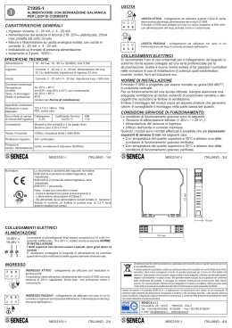
SEPARAZIONE GALVANICA AUTOALIMENTATA
PER LOOP DI CORRENTE
Z110S - 1 Canale
Z110D - 2 Canali
COLLEGAMENTI ELETTRICI
SELF POWERED CURRENT LOOP ISOLATOR
Si raccomanda l'uso di cavi schermati per il collegamento dei segnali; lo
schermo dovrà essere collegato ad una terra preferenziale per la
strumentazione. Inoltre è buona norma evitare di far passare i conduttori
nelle vicinanze di cavi di installazioni di potenza quali inverter, motori,
forni ad induzione ecc.
CARATTERISTICHE GENERALI
INGRESSO 1° CANALE ( sia per Z110S che per Z110D )
INGRESSO PASSIVO : collegamento da utilizzare
con trasduttori in tecnica a 2 fili.
Il trasduttore alimenta il modulo con una corrente
compresa tra i 4 e i 20mA.
Caduta di tensione a 20mA: 7V per RL<160 Ohm;
RL*0,02+3,8 per RL>160 Ohm
10 11 12
SPECIFICHE TECNICHE
Alimentazione:
Autoalimentato dal loop di ingresso.
Ingresso:
Corrente 4 - 20 mA
Caduta di tensione a 20mA:
7V per RL < 160ohm, RL*0,02 +3,8 per RL > 160ohm.
Uscita:
Corrente impressa 4 - 20 mA, max resistenza di carico 500
ohm.
Condizioni ambientali:
Temperatura: 0..50°C, Umidità min:30%, max 90% a 40°C
non condensante.
Errore di
Linearità
Errore dovuto
alla variazione
del carico
0,1% del f.s. 0,02% del f.s./°C 0,1% del f.s. 0,1% del f.s.
Tempo di risposta:
<100 mS (riferiti al 90% del valore finale)
Protezione Ingressi:
Tensione max. 35V
Protezione uscite:
Tensione max. 35V
Normative:
Lo strumento è conforme alle seguenti normative:
EN50081-2 (emissione elettromagnetica, ambiente
industriale)
EN50082-2 (immunità elettromagnetica, ambiente
industriale)
EN61010-1 (sicurezza)
MI000691-I/E/D
mA
+
Z110S - 1 Channel
Z110D - 2 Channel
+
USCITA ATTIVA : Il modulo genera una corrente per il
loop di uscita identica a quella che circola nel loop di
ingresso e può pilotare sul loop di uscita un carico
massimo di 500 ohm.
Non deve esserci nessuna alimentazione sul loop di
uscita.
1 2 3
ITALIANO - 1/4
DIMENSIONI
MI000691-I/E/D
Power supply:
Self Powered from the input (primary) loop.
Input:
Current: 4 - 20 mA
Minimum Volt Drop at 20mA: 7V (all loads up to 160ohm)
Maximum Volt Drop at 20mA 3.8V + (Load Resistance)*0.02V.
Output:
4 - 20 mA (active), max load resistance 500 ohm.
Operating Conditions:
Temperature: 0~50°C, Humidity min:30%, max 90% @ 40°C,
non condensing.
Input measurement
error:
Calibration
Error
mA
Thermal
Coefficient
Linearity
error
Load variation
effect
Response Time:
<100 mS to reach 90% of final value.
Input Protection:
Protected up to 35Vdc Max.
Output Protection:
Protected up to 35Vdc Max.
Standards:
This instrument meets or exceeds the requirements of
EN50081-2 (electromagnetic emissions, industrial
environment)
EN50082-2 (electromagnetic susceptibility, industrial
environment)
EN61010-1 (safety)
mA
MI000691-I/E/D
100 mm
ENGLISH - 3/4
PASSIVE INPUT: Connect the module in the current
loop as shown.
The module is powered by the 4 to 20mA current
loop.
Voltage Drop at 20mA: 3.8V plus Load Volt drop
(0.02*load resistance), minimum 7V
(e.g. with load of 250ohm Volt Drop is :
3.8V + (0.02*250) = 8.80V)
+
ACTIVE OUTPUT: The module generates a current
in the output loop identical to the
current in the input loop. It is capable of driving into a
maximum load of 500_.
4 5 6
INSTALLATION
Questo documento è di proprietà SENECA srl. La duplicazione e la riproduzione sono vietate, se non
autorizzate. Il contenuto della presente documentazione corrisponde ai prodotti e alle tecnologie
descritte. I dati riportati potranno essere modificati o integrati per esigenze tecniche e/o commerciali. Il
contenuto della presente
This document is property of SENECA srl. Duplication and reprodution are forbidden, if not authorized.
Contents of the present documentation refers to products and technologies described in it. All technical
data contained in the document may be modified without prior notice Content of this documentation is
subject to periodical revision.
SENECA s.r.l.
Via Germania, 34 - 35127 - Z.I. CAMIN - PADOVA - ITALY
Tel. +39.049.8705355 - 8705359 - Fax +39.049.8706287
e-mail: [email protected] - www.seneca.it
ITALIANO - 4/4
+
The output loop must NOT be powered.
The Z110S and Z110D are designed for easy mounting on 35mm DIN
rail.
MI000691-I/E/D
MI000691-I/E/D
mA
17,5 mm
NORME DI INSTALLAZIONE
ITALIANO - 2/4
ACTIVE OUTPUT: The module generates a current
in the output loop identical to the
current in the input loop. It is capable of driving into a
maximum load of 500ohm.
1 2 3
mA
I moduli Z110S e Z110D sono progettati per essere montati su guida DIN
46277, in posizione verticale.
MI000691-I/E/D
+
CHANNEL 2 OUPUT (Z110D only)
4 5 6
ISO9001-2000
mA
7 8 9
100 mm
R
CHANNEL 1 OUTPUT (Z110S and Z110D)
CHANNEL 2 INPUT (Z110D only)
USCITA ATTIVA : Il modulo genera una corrente per il
loop di uscita identica a quella che circola nel loop di
ingresso e può pilotare sul loop di uscita un carico
massimo di 500 ohm.
Non deve esserci nessuna alimentazione sul loop di
uscita.
THE INTERNATIONAL CERTIFICATION NETWORK
+
ENGLISH - 1/4
DIMENSIONS
+
+
mA
Voltage Drop at 20mA: 3.8V plus Load Volt drop
(0.02*load resistance), minimum 7V
(e.g. with load of 250ohm Volt Drop is :
3.8V + (0.02*250) = 8.80V)
The output loop must NOT be powered.
USCITA 2° CANALE ( solo per Z110D )
17,5 mm
PASSIVE INPUT: Connect the module in the current
loop as shown.
The module is powered by the 4 to 20mA current
loop.
10 11 12
0,1% off f.s. 0,02% off f.s./°C 0,1% off f.s. 0,1% off f.s.
INGRESSO PASSIVO : collegamento da utilizzare
con trasduttori in tecnica a 2 fili.
Il trasduttore alimenta il modulo con una corrente
compresa tra i 4 e i 20mA.
Caduta di tensione a 20mA: 7V per RL<160 Ohm;
RL*0,02+3,8 per RL>160 Ohm
7 8 9
CHANNEL 1 INPUT (Z110S and Z110D)
TECHNICAL SPECIFICATION
ITALIANO - 3/4
INGRESSO 2° CANALE ( solo per Z110D )
112 mm
4 - 20 mA current input.
Retransmission of input as an isolated 4 - 20 mA output.
Input / output isolation 1500Vac.
Channel to channel isolation 1500Vac (2 channel model Z110D
only).
USCITA 1° CANALE ( sia per Z110S che per Z110D )
mA
ELECTRICAL CONNECTIONS
Screened cable is recommended for signal connections and the screen
should be connected to the
instrument earth. It is good practice to separate signal cables from power
cables and to avoid potential
sources of interference such as electric motors, variable speed drives,
microwave ovens and induction
GENERAL SPECIFICATION
Ingresso corrente 4 - 20 mA.
Misura e ritrasmissione su uscita analogica isolata, con uscita in
corrente 4 - 20 mA.
Isolamento ingresso / uscita 1500Vca.
Isolamento canale / canale 1500Vca (solo nel modello Z110D).
Errori riferiti al campo Errore di
Coefficiente
di misura dell’ingresso: Calibrazione Termico
EN
112 mm
I
R
THE INTERNATIONAL CERTIFICATION NETWORK
ISO9001-2000
MI000691-I/E/D
ENGLISH - 2/4
SENECA s.r.l.
Via Germania, 34 - 35127 - Z.I. CAMIN - PADOVA - ITALY
Tel. +39.049.8705355 - 8705359 - Fax +39.049.8706287
e-mail: [email protected] - www.seneca.it
MI000691-I/E/D
ENGLISH - 4/4
Scaricare