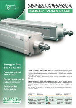
Intelligent Hydraulic Cylinders
Tie Rod Hydraulic Cylinders High
Pressure 230 Bar
Cilindri oleodinamici a tiranti alta
pressione 230 bar
Cat0802.GB+IT
www.vegacylinder.com
I
V230CI
®
Cylinder model V230CI
Modello cilindro V230CI
ØY
ØX
Order compilation symbols - Simbologia per redigere un ordine
V230CI
CI
032 040 050 063 080 100 125 160
Cylinder ROD (ØY)
STELO cilindro
P. I4
014 018 022 028 036 045 056 070
022 028 028 036 045 056 070 110
036 045 056 070 090
Clamping STYLE
Fissaggio
- P. I5-6
CI
A
L
B
M
C
N
050
D
O
E
P
036
G
Q
C
H
T
I
U
O
G
A
F
I
H
Cylinder with magnetic preset
Cilindro con predisposizione magnetica
Cylinder without magnetic preset
Cilindro senza predisposizione magnetica
M
Stroke (Z)
Corsa
- P. I4
MSU1
A
MX2
E
ME6
F
MS1
C
MX5
D
ME5
G
MS2
Cushioning TYPE
TIPO di ammortizzamento
- P. I7
0
1
2
3
4
5
6
Without cushionig or air bleed
Senza ammortizzo e sfiato aria
Head cushioning and air bleed
Ammortizzo e sfiato anteriore
Rear cushioning and air bleed
Ammortizzo e sfiato posteriore
Head and rear cushioning and air bleed
Ammortizzo e sfiato anteriore e posteriore
Head air bleed
Sfiato aria anteriore
Rear air bleed
Sfiato aria posteriore
Head and rear air bleed
Sfiato aria anteriore e posteriore
Oil Ports TYPE
TIPO di orifizi
- P. I7
G
N
M
BSP Thread (GAS)- Filetto BSP (GAS)
G
H
G
NPT Thread - Filetto NPT
Metric Thread - Filetto Metrico
M
0200,0
+
Accessories
Accessori
Oil Ports POSITION
POSIZIONE orifizi
- P. I8
METRIC FEMALE thread
Filetto FEMMINA METRICO
METRIC MALE thread
Filetto MASCHIO METRICO
FLOATING JOINT (not for rod diam. 90, 110 and 140 mm.)
TESTA A MARTELLO (non per steli diam. 90, 110 e 140 mm.)
UNF-UNEF female thread (U.S.A. Standard )
Filetto FEMMINA UNF-UNEF (Standard U.S.A.)
UNF-UNEF male thread (U.S.A. Standard )
Filetto MASCHIO UNF-UNEF (Standard U.S.A.)
....,.
ØX = Bore Alesaggio
ØY = Rod Stelo
Cylinder BORE (ØX)
ALESAGGIO cilindro
- P. I4
N
Rod end TYPE
Estremità STELO
- P. I9
MSU1
Cylinder VERSION
VERSIONE Cilindro
- P. I10
Z
Magnetic Switches
Sensori Magnetici
- P. I10
I
The tie rod cylinder V230CI range is an alternative to the V160CB when a high pressure and temperature are required
Heavy duties as die casting are its specific application field. Bores from 32 to 160 mm., all with magnetic version
alternative, strokes till 1500 mm., depending on the bore (details at page I4).
I cilindri a tiranti serie V230CI rappresentano una valida alternativa ai V160CB nelle applicazioni gravose con alta
pressione ed alta temperatura quali, ad esempio, gli stampi di pressofusione d’alluminio o la tranciatura. Disponibile
negli alesaggi da 32 a 160 mm., tutti con l’opzione dei fine corsa magnetici e corse fino a 1500 mm. a seconda
dell’alesaggio (in dettaglio a pag. I4).
Piston in steel or aluminum
alloy depending on the
version, with PTFE +
bronze seals, FKM Orings
and polyester guide rings,
for a long life.
End stroke magnetic switches, in option for the “Magnetic” version
Sensori magnetici di fine corsa, opzionali, per versione “Magnetica”
Viti
di
regolazione
ammortizzo e sfiato aria
residua nel cilindro, con
dado di bloccaggio.
Pistone (in acciaio o
in lega d’alluminio a
seconda della versione),
con guarnizioni in PTFE
+ Bronzo, O-rings in
FKM e fasce di guida in
poliestere, per una lunga
durata.
Cast iron rod seals
cartridge with
PTFE+Bronze seals, FKM
Orings for a long life
and high temperature
resistance.
Cartuccia portaguarnizioni
in ghisa idraulica con
guarnizioni in PTFE +
Bronzo, O-rings in FKM
per una lunga durata
e resistenza ad alte
temperature.
Aluminum alloy or special
steel tube, depending
the
cylinder
version
- magnetic or non
magnetic - with inner low
roughness finish for high
running speeds.
Camicia lega d’alluminio
o acciaio normale a
seconda della versione
- magnetica o non - con
finitura interna speculare
a bassissima rugosità.
ØX
Cushioning
adjustment
screws and residual air
exit from the cylinders,
with lucknut.
Chrome-plated steel rod, hardened and polished.
Thickness of chromium plating 20 ųm and surface
finish 0,4 ųm Ra, for a longer durability of the seals.
Cushioning system with floating
shock absorber bushing.
Stelo in acciaio bonificato, cromato e lucidato.
Spessore cromatura 20 ųm e finitura superficiale 0,4
ųm Ra, che prolunga notevolmente la durata delle
guarnizioni.
Sistema di ammortizzamento
con boccola flottante.
Maximum Working PRESSURE in Bar - PSI Maximum Nominal delivery (pushing) L/min
Maximum working temperature
PRESSIONE max. di esercizio in Bar - PSI Portata Max. Nominale (in spinta) L/min Maximum piston
Temperatura max. esercizio
speed m/s
Velocità max.
Without cushioning
With cushioning Without cushioning With cushioning pistone m/s MAGNETIC Cylinder NON magnetic Cylinder
Non ammortizzato
Ammortizzato
Non ammortizzato Ammortizzato
Cilindro MAGNETICO Cil. NON magnetico
32
230 - 3335
210 - 3045
4
20
0,5
40
230 - 3335
210 - 3045
7
35
0,5
50
230 - 3335
210 - 3045
10
55
0,5
63
220 - 3190
200 - 2900
18
90
0,5
80
220 - 3120
200 - 2900
30
90
0,3
100
200 - 2900
180 - 2610
45
140
0,3
125
180 - 2610
180 - 2610
70
220
0,3
160
160 - 2320
160 - 2320
120
360
0,3
ØX = Bore Alesaggio
I
80°C - 176° F
160°C - 320°F
V230CI
Product presentation and general features
Presentazione del prodotto e caratteristiche generali
Choice of BORE size and STROKE - Determinazione di ALESAGGIO e CORSA
Table THRUST and TRACTION FORCE in Kg.
Tabella FORZE IN SPINTA e TRAZIONE in Kg.
V230CI
80 bar-1160 PSI
ØX
ØY
032
014
022
018
028
022
028
036
028
036
045
036
045
056
045
056
070
056
070
090
070
110
040
050
063
080
100
125
160
Thrust
Spinta
643
1005
1570
2493
4019
6280
9813
16077
Example of order code:
Esempio di codice ordine:
CI
100 bar-1450 PSI
125 bar-1812 PSI
160 bar-2320 PSI
Traction
Trazione
520
339
801
512
1266
1078
756
2000
1679
1221
3205
2748
2050
5008
4311
3203
7843
6735
4726
13000
8478
Thrust
Spinta
Thrust
Spinta
Thrust
Spinta
050
036
804
1256
1963
3116
5024
7850
12266
20096
Traction
Trazione
650
424
1001
640
1183
1347
945
2500
2099
1526
4007
3435
2563
6260
5389
4004
9804
8419
5908
16250
10598
1005
1570
2453
3895
6280
9813
15333
25120
Traction
Trazione
813
530
1252
800
1978
1684
1181
3125
2623
1908
5008
4294
3203
7825
6736
4805
11675
10103
7090
19500
12718
1286
2010
3140
4985
8038
12560
19625
32154
Traction
Trazione
1040
678
1603
1025
2532
2155
1512
4000
3357
2442
6411
5495
4100
10017
8621
6406
15686
13471
9451
25999
16956
200 bar-2900 PSI
Thrust
Spinta
1608
2512
3925
6231
10048
15700
24531
40192
Traction
Trazione
1300
848
2003
1281
3165
2694
1890
5000
4197
3052
8013
6869
5124
12521
10776
8007
19608
16838
11814
32499
21195
0200,0
Table STANDARD AND REGISTERED STROKES in mm.
Tabella CORSE STANDARD e RACCOMANDATE in mm.
Z
ØX
0020,0 0050,0 0080,0 0100,0 0125,0 0160,0 0200,0 0250,0 0300,0 0350,0 0400,0 0500,0 0600,0 0750,0 0800,0 0900,0 1000,0 1100,0 1500,0
32
40
50
63
80
100
125
160
STANDARD STROKES
CORSE STANDARD
NOT STANDARD STROKES
CORSE FUORI STANDARD
SPECIAL STROKES
CORSE SPECIALI
NOTES: Any stroke can be supplied on request with same delivery time. For strokes shorter than 80 mm. consider as alternative the block cylinders
type V450. For special strokes consider the use of a guide spacer (contact our tech. Dept). Strokes must be specified till the tenth of millimeter.
Stroke tolerance –0\+0,5 mm.
NOTE: Qualunque corsa può essere fornita su richiesta con analogo tempo di consegna. Per corse inferiori ad 80 mm. considerare in alternativa
i cilindri COMPATTI serie V450CM. Per le corse speciali valutare l’utilizzo di distanziale di sovra-guida(contattare ns. uff. tecnico). Le corse vanno
specificate fino al decimo di millimetro. Tolleranza sulla corsa –0\+0,5 mm.
ØX = Bore Alesaggio
ØY = Rod Stelo
Z = Stroke Corsa
I
Choice of CLAMPING style - Determinazione del FISSAGGIO
CI
036
050
C
Base Clamping Style MX5
Fissaggio BASE MX5
D
Front Flange ME5
Flangia anteriore ME5
C
0200,0
V230CI
Example of order code:
Esempio di codice ordine:
NOTE: The fore centring has to be done on the dimension RD - NOTE: Il centraggio anteriore va effettuato sulla quota RD
Rear Flange ME6
Flangia Posteriore ME6
E
ØY
ØB
f9
14
22
18
40
28
22
50
28
36
28
63
36
45
36
80
45
56
45
100 56
70
56
125 70
90
70
160
110
26
34
30
42
34
42
50
42
50
60
50
60
72
60
72
88
72
88
108
88
133
ØX
32
ØX = Bore Alesaggio
BG
E
F
FB
H 13
G
GF
J
KB
PY
PJ+
R
Js
14
ØRD
f10
20
60
10
9
45
55
32
12
60
72
40
20
65
12
11
48
60
40
14
63
88
22
80
16
13,5
49
65
40
16
67
24
90
16
13,5
49
65
40
16
30
120
20
17,5
55
75
50
30
130
22
17,5
58
80
35
165
22
23
58
45
210
22
28
78
ØY = Rod Stelo
TG
Js
13
TO
Js
14
UO
50
M8×1,25 36,8
70
85
41
62
M10×1,5
87
110
98
52
70 M12×1,75 54,4 105
130
74
99
65
76 M12×1,75 65
117
145
20
77
118
83
105
M16×2
82,6 150
185
50
20
83
119
97
110
M16×2
100
170
210
80
50
26
135 M22×2,5 126
208
250
100
75
33
170
261
310
Z = Stroke Corsa (P.I4)
89,5 130,5 126
95
174
eg. ØX = 50 ,
I
161
RT
M27×3
46
161
V
8
14
8
13
9
11
9
11
13
15
9
11
11
9
10
10
10
12
10
12
12
WF
WH ZJ+
34
24
143
36
24
169
41
25
183
48
32
190
50
30
218
55
33
221
62
40
238
62
40
315
ØY = 36, Z = 200mm : ZJ + Z = 183 + 200 = 383 mm
Choice of CLAMPING style - Determinazione del FISSAGGIO
Example of order code:
Esempio di codice ordine:
050
036
F
G
G
0200,0
Head Foot MS1
Piedino anteriore MS1
F
V230CI
CI
Available up to bore Ø125 mm only - Disponibile solo fino all’alesaggio Ø125 mm
Head and Rear Foot MS2
Piedino anteriore e posteriore MS2
G
Available up to bore Ø125 mm only - Disponibile solo fino all’alesaggio Ø125 mm
Extended Rear Tie Rods MX2
Tiranti prolungati MX2
A
ØX
ØY
BB
14 35
22
40 18
28 40
22
50 28 45
36
28
63 36 45
45
36
80 45 60
56
45
100 56 60
70
56
125 70 80
90
70 100
160 110
32
ØX = Bore Alesaggio
SU
SW
TG
Js
13
TS
US WH XS
YH
YP
YY ZJ+
12
24
10
36,8
77
95
24
48
51
33
37
143
113
13
20
12
46
87
110
24
44
54
34
40
169
40
13,5 111
19
34
13
54,4 105 130
25
59
57
37
41
183
40
45
13,5 108
24
33
17
120 150
32
65
62
44
41
190
5
50
60
17,5 132
26
37
19
82,6 150 185
30
67
60
46
43
218
16
5
50
65
17,5 116
32
44
28
100 170 210
33
77
65
49
48
221
80
16
6
50
82,5
20
132
32
44
22
126 210 255
40
84
74
58
44
238
-
-
-
-
-
-
-
-
-
-
161
40
-
-
-
-
315
DD
E
GF
H
HP
J
LH
M8×1,25
60
55
12
4
32
30
9
85
M10×1,5
65
60
12
4
40
32,5
11
M12×1,75
80
65
12
4
40
M12×1,75
90
65
15
5
M16×2
120
75
16
M16×2
130
80
M22×2,5
165
M27×3
210
ØY = Rod Stelo
Z = Stroke Corsa (P.I4)
SB SS+ ST
eg. ØX = 50 ,
I
65
-
-
ØY = 36, Z = 200mm : ZJ + Z = 183 + 200 = 383 mm
Choice of Cushioning and Type Of Oil Delivery Ports
Determinazione dell’ Ammortizzamento e Tipo Di Orifizi
Cushioning lenght mm.(nearly)
Lunghezza ammortizzamento in mm. (circa)
CUSHIONING TYPE
TIPO DI AMMORTIZZAMENTO
Without cushioning or air bleed
Senza ammortizzo e sfiato aria
Head cushioning and air bleed
Ammortizzo e sfiato anteriore
Rear cushioning and air bleed
Ammortizzo e sfiato posteriore
Head and rear cushioning and air bleed
Ammortizzo e sfiato anteriore e posteriore
Head air bleed
Sfiato aria anteriore
Rear air bleed
Sfiato aria posteriore
Head and rear air bleed
Sfiato aria anteriore e posteriore
0
1
2
3
4
5
6
32
Head and rear
Anteriore e posteriore
17
40
20
50
20
63
20
80
23
100
23
125
25
160
30
ØX
ØX = Bore Alesaggio
Example of order code:
Esempio di codice ordine:
CI
050
036
C
0
G
0200,0
TYPE OF PORTS of the cylinder
TIPO DI ORIFIZI del cilindro
EE
ØX
BSP
NPT
METRIC
METRICO
32
40
50
63
80
100
125
160
1/4”
3/8”
1/2”
1/2”
3/4”
3/4”
3/4”
1”
1/4”
3/8”
1/2”
1/2”
3/4”
3/4”
3/4”
1”
M14x1,5
M18x1,5
M22x1,5
M22x1,5
M27x2
M27x2
M27x2
M33x2
TIPE OF PORTS
TIPO DI ORIFIZI
G
N
M
BSP Thread (GAS)
Filetto BSP (GAS)
NPT Thread (Standard USA)
Filetto NPT (Standard USA)
Metric thread
Filetto Metrico
Before establishing the cylinder cushioning it is advisable to verify the maximum amount of energy absorbed following the calculations and the
table shown below.
Prima di definire l’ammortizzamento di un cilindro è bene verificare l’energia massima assorbibile secondo i calcoli e la tabella sotto.
Vertical application
Applicazione in verticale
A
B
Energy in joules
E = Energia in joules
Oil pressure in bar
P = Pressione olio in bar
Max. speed in m/s
EA = ½mV² - mg x 0,02
EB = ½mV² + mg x 0,02
V = Velocità massima in m/s
Total mass in Kg.
m = Massa totale in Kg.
Acceleration due to gravity 9,81 m/s2
g = Acceleraz. di gravità 9,81 m/s2
Horizontal application
Applicazione in orizzontale
A = Trazione
E = ½mV²
B = Spinta
Traction
Thrust
Back Side (rod backward)
Lato Testata Posteriore (rientro dello stelo)
ENERGY IN JOULE
ENERGIA AMMORITIZZABILE IN JOULE
Front Side (rod forward)
Lato Testata Anteriore (uscita dello stelo)
OIL DELIVERY PRESSURE IN BAR
PRESSIONE DI ALIMENTAZIONE IN BAR
I
V230CI
Cylinder CUSHIONING
AMMORTIZZAMENTO del cilindro
Choice of Cushioning and Type Of Oil Delivery Ports
Determinazione dell’ Ammortizzamento e Tipo Di Orifizi
V230CI
Example of order code:
Esempio di codice ordine:
CI
050
036
C
O
G
H
0200,0
Head
Rear
Posteriori Anteriori
CUSHIONING
SCREW POSITION
POSIZ. VITE REG.
AMMORTIZZ.
Rear
Head
Posteriori Anteriori
PORT POSITION
POSIZIONE
ORIFIZIO
H A B C D G I L N OM P Q T U E H A B C D G I L N OM P Q T U E H A B C D G I L N OM P Q T U E
1 1 1 1 2 2 2 2 3 3 3 3 4 4 4 4 1 1 1 1 2 2 2 2 3 3 3 3 4 4 4 4 1 1 1 1 2 2 2 2 3 3 3 3 4 4 4 4
* * * *
* * * * # # # #
1 2 3 4 1 2 3 4 1 2 3 4 1 2 3 4 1 2 3 4 1 2 3 4 1 2 3 4 1 2 3 4 1 2 3 4 1 2 3 4 1 2 3 4 1 2 3 4
*
* # *
* # *
* # *
#
3 3 3 3 4 4 4 4 1 1 1 1 2 2 2 2 2 2 2 2 4 4 4 4 2 2 4 2 2 2 2 2 3 3 3 3 1 1 1 1 1 1 1 1 2 2 2 2
3 4 1 2 3 4 1 2 3 4 1 2 3 4 1 2 2 4 2 2 2 4 2 2 2 4 4 2 2 4 2 2 3 1 1 2 3 1 1 2 3 1 1 2 3 1 1 2
A-C
D-E
F-G
*: With this configuration elbow joints cannot be applied. Con questa configurazione non si possono applicare raccordi a gomito
#: Configuration not available with mounting style “F”. Configurazione non disponibile con fissaggio “F”.
IF THERE ARE NOT PARTICULAR REQUIREMENTS, THE STANDARD CONFIGURATION IS “H” .
SE NON CI SONO PARTICOLARI ESIGENZE LA CONFIGURAZIONE “H” E’ QUELLA STANDARD
2
3
Head
Anteriore
Rear
Posteriore
1
4
I
Choice of Rod End Style - Determinazione dell’ Estremità Dello Stelo
Example of order code:
Esempio di codice ordine:
CI
050
036
C
O
G
H
G
0200,0
DESCRIPTION OF ROD END STYLE
DESCRIZIONE TIPO DI ESTREMITA'
METRIC FEMALE thread
Filetto FEMMINA METRICO
G
METRIC MALE thread
Filetto MASCHIO METRICO
A
FLOATING JOINT (not for rod diam. 90, 110 and 140 mm.)
TESTA A MARTELLO (non per steli diam. 90, 110 e 140 mm.)
F
UNF-UNEF female thread (U.S.A. Standard )
Filetto FEMMINA UNF-UNEF (Standard U.S.A.)
I
UNF-UNEF male thread (U.S.A. Standard )
Filetto MASCHIO UNF-UNEF (Standard U.S.A.)
H
V230CI
G/I
F
A/H
The end and the length of the rod can be supplied differently from the options shown in this catalogue. In
such a case, the customer should specify the code “S” (special) when placing the order and forward the
required dimensions of the rod accompanied by a sketch. If one of the rigid MOUNTING STYLE is chosen (A,
C, D, E, F, G) it is important to make a careful assessment of the most suitable type of coupling between the
piston rod and the part to be actuated. This is due to the fact that technical and practical requirements (such
as inclined planes, die pins, die cheeks, extractor carriages, etc.) frequently make it impossible to achieve
a correct alignment between the piston rod movement axis and the actuated mechanical part. A simple
corrective system is to fit a floating joint rod end “F” which, unlike a threaded attachment system, allows a
radial clearance between the rod and the moving part. As an alternative, you might use a floating joint on
the female thread “G”; in such a case, see the page concerning the ACCESSORIES.
L’estremità e la lunghezza dello stelo possono essere forniti diversi da quanto proposto dal presente catalogo. In tal caso, al momento dell’ordinazione,
si dovrà specificare la codifica “S” (speciale) e inoltrare le dimensioni accompagnate da uno schizzo. Scegliendo un fissaggio rigido (A, C, D, E,
F, G) bisognerà valutare attentamente l’ancoraggio più idoneo fra stelo e pezzo da movimentare. Si riscontra infatti molto spesso che necessità
tecnico-pratiche (es. piani inclinati, spine, guance di stampi, carrelli di estrazione, ecc.) non permettono un corretto allineamento tra l’asse di
traslazione dello stelo e l’organo comandato. Un semplice sistema correttivo è dato dall’applicazione della testa a martello “F” che, diversamente
dall’ancoraggio con filetto, consente un gioco radiale tra stelo ed organo in movimento. In alternativa è possibile una testa a martello riportata sul
filetto femmina “G”; in tal caso vedere catalogo ACCESSORI.
ØX
32
40
50
63
80
100
125
160
ØY
B
14
22
18
28
22
28
36
28
36
45
36
45
56
45
56
70
56
70
90
70
110
13
21
17
27
21
27
35
27
35
44
35
44
55
44
55
68
55
68
88
68
108
C
METRIC
M8×1,25
M12×1,75
M10×1,5
M20×2,5
M12×1,75
M20×2,5
M27×3
M20×2,5
M27×3
M33×3,5
M27×3
M33×3,5
M42×2
M33×3,5
M42×2
M48×2
M42×2
M48×2
M64×3
M48×2
M80×3
* dimensions with fixing type « D »
* quote con fissaggio « D »
UNF-UNEF
5/16-24
1/2-20
3/8-24
3/4-16
1/2-20
3/4-16
1-12
3/4-16
1-12
1-5/16-18
1-12
1-5/16-18
1-11/16-18
1/5/16-18
1-11/16-18
1-7/8-16
1-11/16-18
1-7/8-16
2-1/2-16
1-7/8-16
3-1/8-16
D
E
F
15
20
18
30
20
30
40
30
40
50
40
50
60
50
60
60
60
60
80
60
100
8
8
6
8
8
8
11
8
11
12
11
12
14
12
14
18
14
18
18
18
18
16
22
18
28
22
28
36
28
36
45
36
45
56
45
56
63
56
63
85
63
95
K
METRIC
M12×1,25
M16×1,5
M14×1,5
M20×1,5
M16×1,5
M20×1,5
M27×2
M20×1,5
M27×2
M33×2
M27×2
M33×2
M42×2
M33×2
M42×2
M48×2
M42×2
M48×2
M64×3
M48×2
M80×3
UNF-UNEF
1/2-20
5/8-18
9/16-18
3/4-16
5/8-18
3/4-16
1-12
3/4-16
1-12
1-1/4-12
1-12
1-1/4-12
1-11/16-18
1-1/4-12
1-11/16-18
1-7/8-16
1-11/16-18
1-7/8-16
2-1/2-16
1-7/8-16
3-1/8-16
ØM
N
P
13
21
17
27
21
27
35
27
35
44
35
44
55
44
55
68
55
68
88
68
108
8
14
10
14
14
14
18
14
18
22
18
22
26
22
26
34
26
34
40
34
50
11
18
15
24
18
24
32
24
32
40
32
40
50
40
50
•
50
•
•
•
•
• The rod is made with 3 equidistant holes and not with the standard key-way
• Lo stelo è realizzato con 3 fori equidistanti e non con la chiave standard
I
ØR
V
8
13
11
18
13
18
21
18
21
33
21
33
40
33
40
50
40
50
64
54
80
8
14
8
13
9
12
9
11
13
15
9
11
11
9
10
10
10
12
10
12
12
ØX = Bore Alesaggio
WF*
WH
34
24
36
24
41
25
48
32
50
30
55
33
62
40
62
40
ØY = Rod Stelo
Choice of cylinder VERSION - Scelta della VERSIONE
Example of order code:
Esempio di codice ordine:
CI
050
036
C
O
G
H
G
M
0200,0
V230CI
DESCRIPTION - DESCRIZIONE
Cylinder WITH MAGNETIC PRESET (switches not included)
Cilindro CON PREDISPOSIZIONE MAGNETICA (sensori non inclusi)
M
Cylinder WITHOUT magnetic preset.
Cilindro SENZA predisposizione magnetica.
N
MAGNETIC SWITCHES (usually two for cylinder)
SENSORI MAGNETICI di fine corsa (solitamente due per cilindro)
Example of order code:
Esempio di codice ordine:
SWITCHES TO BE ORDERED SEPARATELY FROM THE CYLINDER.
SENSORI DA ORDINARE SEPARATAMENTE AL CILINDRO.
MSU1
+24V
I/U
0V
Wire Colour Colore Conduttori
Brown Marrone = +24V DC
Blue Blu
= 0V DC
Black Nero
= In/Out Contact Contatto In/Out
White Bianco
= In/Out Contact Contatto In/Out
I/U = In/Out In/Out
Switches Technical Data MSU1
Dati tecnici sensori MSU1
Supply - Alimentazione
24 VDC ± 10%
Protection - Protezione
polarity inversion - inversione di polarità
Output - Tipo di segnale
clean contact 0V - contatto pulito 0V
Max. switching voltage - Tensione Max. commutabile
125 VAC
Max. switching current - Corrente Max. commutabile
800 mA
Max. switching frequency - Frequenza max. di commutazione
60 Hz
Max. switching power - Potenza Max. commutabile
20 W
Electric life at rated power (operations) - Vita elettrica
10,000,000
Hysteresis - Isteresi
±0,02 mm typical - tipico ±0,02 mm
24 volt disconnection delay - Ritardo alla disinserzione a 24v
15 m sec.
Max. working temperature - Temperatura Max. di esercizio
+80° C - +176° F
Cable (Extraflex armoured + transp. PVC sheath) Cavo (corazzato Extraflex + guaina PVC trasp.) mm
Ø6 x 3000
Section wires - Sezione conduttori
4x0,25 mm2
Serial signal connection - Collegamento del segnale in serie
ok, max 6 switches - si, max 6 sensori
Switch type - Tipo di sensore
electronic, magnet-resistive - elettronico magnetosensitivo
Repeatability - Ripetibilità
> 0,05 mm.
ON minimum time - Tempo minimo in ON
3 msec.
Max. flow speed - Velocita max. di passaggio
15 mt/sec.
Degree of protection against liquids - Grado di protezione ai liquidi
IP 67 (DIN 40050)
Dimensions - Dimensioni mm
39x24x28
Minimum stroke mm.with switches
Corsa minima mm. con sensori
1
Dimensions (Max.)
Dimensioni ingombro (Max.)
Mounting type
Tipo di montaggio
ØX
1
2
3
ØX
KA
KB
32
45
65
10
32
3,4
17,3
40
45
56
10
40
7,2
20
50
45
47
10
50
6,4
17,2
63
45
10
10
63
7,3
18,4
80
45
10
10
80
2,7
12,2
100
45
10
10
100
6,8
16,7
125
45
10
10
125
4,2
11,9
160
45
10
10
160
9
19
2
3
I10
ØX = Bore Alesaggio
Spare Parts - Ricambi
1
…
Article Code
Codice Articolo
Additional set code
Indicazione d’assieme
RI
025
012
6010
A
6
7
8
9
10
Cylinder stroke
Corsa cilindro
Cylinder rod diam
Stelo cilindro
5
Cylinder bore
Alesaggio cilindro
4
Type
Modello
Example of order code:
Esempio di codice ordine:
3
V230CI
1 Cushioning and air bleed
screw with locknut
Vite reg. ammortizzo e sfiato
aria con contro dado
2 Magnetic switch
Sensore magnetico
3 Magnet - Magnete
4 Piston seals
Guarnizione pistone
5 Piston - Pistone
6 Tube - Camicia
7 Rod - Stelo
8 Rod seals
Guarnizioni stelo
9 Rod cartridge
Cartuccia porta guarnizioni
10 Rod end
Estremità dello stelo
2
*
6010
A
Rod seals kit - Serie guarnizioni stelo
8
6020
A
Piston seal kit - Serie guarnizioni pistone
4
RI
…
RI
…
RI
…
…
0310
RI
…
…
0310
RI
…
1912
…
Tube for magnetic cylinder - Camicia per cilindro magnetico
RI
…
1911
…
Tube for non magnetic cylinder - Camicia per cilindro non magnetico
RI
…
…
1510
A
Magnetic piston with seals - Pistone magnetico con guarnizioni
RI
…
…
1512
A
Non magnetic piston with seals - Pistone non magnetico con guarnizioni
RI
…
6050
RI
…
2510
RI
…
…
110 …
RI
…
…
113 …
RI
…
…
154 …
RI
…
…
RI
…
…
RI
…
RI
Rod cartridge without seals - Cartuccia stelo senza guarnizioni
Rod cartridge with seals - Cartuccia stelo con guarnizioni
A
9
8+9
6
6
3+4+5
4+5
Magnet - Magnete
3
Screw with locknut for cushioning - Vite con dado per regolaz. ammortizzo
1
…
Rod without cushioning - Stelo non ammortizzato
7
…
Rod with cushioning - Stelo ammortizzato
A
…
Non magnetic rod-piston without cushioning - Stelo\pistone non magnetico non ammortizz.
4+5+7
156 …
A
…
Non magnetic rod-piston with cap cushioning - Stelo\pistone non magnetico ammortizz. post.
4+5+7
155 …
A
…
Non magnetic rod-piston with head cushioning - Stelo\pistone non magnetico ammortizz. ant.
4+5+7
…
157 …
A
…
Non magnetic rod-piston with head and cap cushioning. - Stelo\pistone non magnetico ammortizz. ant. + post.
…
…
150 …
A
…
Magnetic rod-piston without cushioning - Stelo\pistone magnetico non ammortizz.
3+4+5+7
RI
…
…
152 …
A
…
Magnetic rod-piston with cap cushioning - Stelo\pistone magnetico ammortizz. post.
3+4+5+7
RI
…
…
151 …
A
…
Magnetic rod-piston with head cushioning - Stelo\pistone magnetico ammortizz. ant.
3+4+5+7
RI
…
…
153 …
A
…
Magnetic rod-piston with head and cap cushioning - Stelo\pistone magnetico ammortizz. ant. + post.
3+4+5+7
A
Rod end type to
be communicated
for rod and rod/
piston group
0
Metric male thread "A" - Filetto maschio Metrico "A"
1
Metric female thread "G" - Filetto femmina Metrico "G"
2
Floating joint "F" - Testa a martello "F"
Estremità stelo
da indicare
per stelo
e gruppo
stelo\pistone.
3
Metric male thread "E" - Filetto maschio Metrico "E"
4
UNF-UNEF male thread "H" - Filetto maschio UNF-UNEF "H"
5
UNF-UNEF female thraed "I" - Filetto femmina UNF-UNEF "I"
6
Rod end type on drawing "S" - Terminale a disegno "S"
I11
7
4+5+7
10
V230CI
®
www.vegacylinder.com
I12
Scaricare