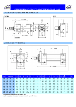
[
]
CARATTERISTICHE TECNICHE
TECHNICAL CHARACTERISTICS
CILINDRI IDRAULICI ISO 6022
ISO 6022 HYDRAULIC CYLINDERS
CARATTERISTICHE TECNICHE / SPECIFICATIONS
Cilindri a norma
ISO 6022 - DIN 24333
Standard cylinders
Alesaggi
Bore
mm
Alesaggi da 50 a 320
Bore from 50 to 320
Pressione
Pressure
bar
nominale 250
operating
massima
max
Massima velocità
Max speed
m/s
standard 0.5
basso attrito
low-friction (vers. Y) (vers. W) 1
Temperatura fluido
Fluid temperature
°C
Corsa massima
Max stroke
mm
standard -20 +80 Viton® W
320
-20 +150
6000
Tolleranza sulla corsa
Stroke tolerance
Norma ISO 8131
0 + 2 mm ISO 8131 Standard
Fluido
Fluid
Olio idraulico minerale / Hydraulic mineral oil
Esteri fosforici / Phosphoric esters (vers. W)
Acqua glicole / HFC-fluid (vers. N)
Viscosità
Viscosity
X
12... 90 mm2/S
VERSIONE BASE / BASIC VERSION
A
FLANGIA ANTERIORE / FRONT FLANGE
ISO MF3
B
Rif.
Ref.
Componente
Components
Materiale
Material
1
Raschiapolvere
Wiper
NBR + PTFE
2
Boccola di guida
Guide bushing
Bronzo
Bronze
3
Guarnizione stelo
Rod seal
NBR + PTFE
4
Guarnizioni OR con antiestrusione
O-Ring seal with anti-extrusion
NBR + PTFE
5
Spillo regolazione frenatura (sfiato)
Cushioning adjusting (air bleed)
Acciaio
Steel
6
Guarnizioni OR
O-Ring seal
NBR + PTFE
7
Stelo
Piston rod
Acciaio bonificato cromato
Hardened and tempered
chromeplated steel
8
Freno anteriore
Front cushioning
Acciaio temprato
Hardened steel
9
Pistone
Piston
Acciaio
Steel
10
Guarnizione pistone
Piston seal
NBR + PTFE
11
Freno posteriore
Rear cushioning
Acciaio temprato
Hardened steel
12
Testata posteriore
Rear head
Acciaio
Steel
13
Camicia
Cylinder body
Acciaio
Steel
14
Testata anteriore
Front head
Acciaio
Steel
15
Flangia chiusura
Closing flange
Acciaio
Steel
16
Aggiornamenti su / updates on www.confortinet.com
Specifiche
Specifications
Cava
Groove
FLANGIA POSTERIORE / REAR FLANGE
ISO MF4
D
ISO 7425/2
CERNIERA CON SNODO / BALL JOINTED EYE
ISO MP5
C
spess. 0.025 mm
ISO f7 - Ra 0.20 µm
Cava
Groove
ISO 7425/1
Levigato / Honed
H8 - Ra 0.40 µm
CERNIERA MASCHIO / MALE CLEVIS
ISO MP3
H
PERNI INTERMEDI / INTERMEDIATE TRUNNIONS
ISO MT4
E
PIEDINI / FEET
ISO MS2
4/11 - Copyright © Conforti Oleodinamica
[
TABELLE TECNICHE
TECHNICAL TABLES
]
CILINDRI IDRAULICI ISO 6022
ISO 6022 HYDRAULIC CYLINDERS
DIAGRAMMA PER LA SCELTA DELLO STELO / ROD SELECTION CHART
LI (mm)
FATTORI DI CORSA “FC”
STROKE “FC” FACTOR
Carico (daN) / Load (daN)
LI = FC x CO
LI = lunghezza ideale / ideal lenght (mm)
FC = fattore di corsa / stroke factor
CO = corsa / stroke (mm)
SEZIONI E FATTORI DI FRENATURA / BRAKING SECTIONS AND STROKES
Alesaggio
Bore
50
63
80
100
125
140
160
200
In spinta M1
=
Push M1
g . (PF . SF – P1 . S1) . LF . 2
1000 . V2
In tiro M2
=
Pull M2
g . (PF . SF – P1 . S3) . LF . 2
1000 . V2
250
320
M1/M2
Carico di frenatura (daN)
Braking load (daN)
P1
Pressione lavoro (bar)
Working pressure (bar)
PF
Pressione frenatura (max. 350 bar)
Braking pressure (max 350 bar)
S1/S3
Sezioni lavoro (cm2)
Work section (cm2)
SF
Sezione frenatura (cm2)
Braking section (cm2)
g
9.81
LF
Lunghezza frenatura (mm)
Braking length (mm)
V
Velocità (m/sec)
Speed (m/sec)
4/11 - Copyright © Conforti Oleodinamica
Stelo
Rod
32
36
40
45
50
56
63
70
80
90
90
100
100
110
125
140
160
180
200
220
S1
S2
S3
SF
LF
cm2
cm2
cm2
cm2
mm
8.3
32
13.8
32
23.8
40
37.8
40
56
40
67
46
99
46
151
65
222
60
388
60
19.6
31.2
50.3
78.5
123
154
201
314
491
804
8
11.6
10.2
9.4
12.6
18.6
15.9
15.3
19.6
30.7
24.6
25.7
31.2
47.3
38.5
40
50.3
72.7
64
59
64
90
78.5
75.5
78.5
122.5
95
106
123
191
154
160
201
290
254
237
314
490
380
424
Aggiornamenti su / updates on www.confortinet.com
17
[
ANCORAGGI
MOUNTINGS
]
CILINDRI IDRAULICI ISO 6022
ISO 6022 HYDRAULIC CYLINDERS
VERSIONE BASE / BASIC VERSION
X
FLANGIA ANTERIORE / FRONT FLANGE
A
ISO MF3
FLANGIA POSTERIORE / REAR FLANGE
B
ISO MF4
CERNIERA CON SNODO / BALL JOINTED EYE
D
ISO MP5
CERNIERA MASCHIO / MALE CLEVIS
C
ISO MP3
PERNI INTERMEDI / INTERMEDIATE TRUNNIONS
H
ISO MT4
PIEDINI / FEET
E
ISO MS2
18
Disegni e modelli 3D CAD / drawings and 3D CAD models on www.confortinet.com
4/11 - Copyright © Conforti Oleodinamica
[
DIMENSIONI
DIMENSIONS
]
Alesaggio
Bore
50
63
80
100
125
140*
160
200
250
320
B f8
BA f8
BD
BW
BX
CD H9
CX H7
D
EW
EX
EE
F
FB
FC
L
LT
LH h10
LX
PJ
PJ1
SB
SC
SE
ST
SS
TD f8
TL
TM
TS
UC
US
UV
VD
WC
XC
XO
XS
XV min
XV max
Y
ZB
ZB3
ZP
63
63
38
27
27
32
32
105
32
32
G 1/2"
25
8 x Ø 13.5
132
40
40
60
38
120+
120+
11
15.5
15.5
32
55+
32
25
112
135
155
160
108
4
22
305+
305+
130
187
132+
98
244+
316++
265+
75
75
48
35
35
40
40
124
40
40
G 3/4"
28
8 x Ø 13.5
150
50
50
68
50
136+
136+
13.5
17.5
17.5
37
55+
40
32
125
155
175
185
124
4
25
348+
348+
147.5
212
137+
107
274+
350++
298+
90
90
58
40
40
50
50
148
50
50
G 3/4"
32
8 x Ø 17.5
180
63
63
80
61.5
156+
156+
17.5
22.5
22.5
42
55+
50
40
150
185
210
225
148
5
28
395+
395+
170.5
245
155+
120
305+
396++
332+
110
110
73
52
52
63
63
175
63
63
G 1"
36
8 x Ø 22
212
71
71
95
71
172+
172+
22
27.5
27.5
52
55+
63
50
180
220
250
265
175
5
32
442+
442+
192.5
280
160+
134
340+
440++
371+
132
132
88
60
60
80
80
208
80
80
G 1"
40
8 x Ø 22
250
90
90
115
90
205+
214+
26
30
30
62
60+
80
63
224
270
290
325
218
6
36
520+
520+
230
340
180+
153
396+
520++
430+
145
145
98
65
65
90
90
255
90
90
G 1 1/4"
40
8 x Ø 26
300
115
115
135
113
208+
208+
30
35.5
35.5
77
61+
90
70
265
325
340
390
260
5
36
580+
580+
254.5
380
200+
181
430+
570++
465+
160
160
108
84
84
100
100
270
100
100
G 1 1/4"
45
8 x Ø 26
315
112
112
145
112
235+
240+
33
37.5
37.5
77
79+
100
80
280
340
360
405
280
5
40
617+
617+
265.5
400
220+
185
467+
610++
505+
200
200
133
102
102
125
125
330
125
125
G 1 1/4"
56
8 x Ø 33
385
160
160
170
145
278+
280+
40
45
45
87
90+
125
100
335
405
440
480
330
10
45
756+
756+
315
450
260+
220
550+
720++
596+
250
250
180
130
130
160
160
412
160
160
G 1 1/2"
63
8 x Ø 39
475
200
200
215
178
325+
320+
52
50
50
112
120+
160
125
425
520
540
620
412
12
50
903+
903+
360
540
300+
260
652+
840++
703+
320
320
220
162
162
200
200
510
200
200
G 1 1/2"
80
8 x Ø 45
600
250
250
260
230
350+
350+
62
60
60
152
120+
200
160
530
620
675
740
510
14
56
1080+
1080+
425
625
325+
310
764+
970++
830+
32
40
50
Stelo
Rod
A
CH
KK
KF
(mm)
CILINDRI IDRAULICI ISO 6022
ISO 6022 HYDRAULIC CYLINDERS
36
45
56
63
70
80
90
90
100
100
110
125
140
160
180
200
220
36
36
45
45
56
56
63
63
85
85
90
90
95
95
112
112
125
125
160
160
28
32
34
36
43
46
52
60
65
75
75
–
–
–
–
–
–
–
–
–
M27x2 M27x2 M33x2 M33x2 M42x2 M42x2 M48x2 M48x2 M64x3 M64x3 M72x3 M72x3 M80x3 M80x3 M100x3 M100x3 M125x4 M125x4 M160x4 M160x4
–
M27x2
–
M33x2
–
M42x2
–
M48x2
–
M64x3
–
M72x3
–
M80x3
–
M100x3
–
M125x4
–
M160x4
+ = sommare la corsa / add the stroke
++ = sommare il doppio della corsa / add the double of the stroke
* alesaggio non contemplato nella normativa ISO 6022
bore not specified in ISO 6022 standard
ESTREMITÀ STELO / ROD END
STANDARD
4/11 - Copyright © Conforti Oleodinamica
SF
FEMMINA / FEMALE
Aggiornamenti su / updates on www.confortinet.com
19
[
OPZIONI ED ESECUZIONI SPECIALI
OPTIONS AND SPECIAL EXECUTIONS
]
CILINDRI IDRAULICI ISO 6022
ISO 6022 HYDRAULIC CYLINDERS
Per la scelta di qualsiasi opzione o variante rispetto al cilindro standard, si consiglia di utlizzare l’apposito servizio sul sito www.confortinet.com
To choose an option or a variation of the standard cylinder, please use our service available on www.confortinet.com
OPZIONI / OPTIONS
ORIENTAMENTO CONNESSIONI
PORT LOCATION
CODICE ORDINAZIONE / ORDERING CODE
EE1
1
2
CONNESSIONI
OIL PORT
G 1/2
EE2
1 4
EE1
2
4
EE1 Bocca olio anteriore
Front head oil port
EE2 Bocca olio posteriore
Rear head oil port
3
Posizione bocca
Oil port position
2
Dimensione bocca olio
Size of oil port
3
Maggiorate / Oversize
Standard
Alesaggio
Anteriore Posteriore Anteriore Posteriore
Bore
Front
Rear
Front
Rear
G 1/2"
G 3/4"
G 1/2"
G 3/4"
50
G 3/4"
G 1"
G 3/4"
G 1"
63
G 3/4"
G 1"
G 3/4"
G 1"
80
G 1"
G 1 1/4"
G 1"
G 1 1/4"
100
G 1"
G 1 1/4"
G 1"
G 1 1/4"
125
G 1 1/4"
G 1 1/2"
G 1 1/4"
G 1 1/2"
140
G 1 1/4"
G 1 1/2"
G 1 1/4"
G 1 1/2"
160
G 1 1/4"
G 1 1/2"
G 1 1/4"
G 1 1/2"
200
G 1 1/2"
G 2"
G 1 1/2"
G 2"
250
G 1 1/2"
–
G 1 1/2"
–
320
ESECUZIONI SPECIALI / SPECIAL VERSIONS
SD
DRENAGGIO BOCCOLA / BUSHING DRAIN
Il drenaggio della boccola impedisce l’accumulo di fluido dietro al raschiatore.
Una connessione situata tra il raschiatore e la tenuta a labbro consente il rinvio al serbatoio del fluido.
Il drenaggio è normalmente posizionato sullo stesso lato della bocca olio.
The bushing drain avoids the accumulation of liquid behind the scraper.
A connection between the scraper and the lip seal allows to send the fluid back to the tank.
The drain is usually installed on the same side of the oil head.
SP
ESECUZIONE CON SENSORI DI PROSSIMITÀ / PROXIMITY SWITCHES
Forniscono un segnale elettrico in corrispondenza dell’avvenuto posizionamento vicino al fine corsa
del cilindro. Previsti per cilindri frenati, posizionati normalmente sul lato 4.
Codici: SPV = Sensore anteriore
SPZ = Sensore posteriore
SPK = Sensore anteriore e posteriore
They give an electrical signal when the stroke end is near.
For cylinders with cuschioning, positioned on side 4.
Codes: SPV = Front sensor
SPZ = Back sensor
CONNESSIONI SAE 3000 / SAE CONNECTIONS 3000
Alesaggio
Bore
50
63
80
100
125
140
160
200
250
320
RRX
RRH
RRK
20
Standard
Anteriore
Posteriore
Front
Rear
–
–
1/2"
1/2"
1/2"
1/2"
3/4"
3/4"
3/4"
3/4"
1"
1"
1"
1"
1"
1"
1 1/4"
1 1/4"
1 1/4"
1 1/4"
SPK = Front and back sensor
Maggiorate / Oversize
Anteriore
Posteriore
Front
Rear
–
–
–
–
–
–
1"
1"
1"
1"
1 1/4"
1 1/4"
1 1/4"
1 1/4"
1 1/4"
1 1/4"
1 1/2"
1 1/2"
1 1/2"
1 1/2"
Stelo INOX / Stainless steel rod
Stelo temprato / Hardened rod
Stelo Nikrom / Nikrom rod
Aggiornamenti su / updates on www.confortinet.com
4/11 - Copyright © Conforti Oleodinamica
[
CODICE DI ORDINAZIONE
ORDERING CODE
]
CILINDRI IDRAULICI ISO 6022
ISO 6022 HYDRAULIC CYLINDERS
CODICE ORDINAZIONE / ORDERING CODE
I campi in cui sono stati inseriti
i valori di esempio sono obbligatori.
The fields containing sample values
are compulsory.
Serie
Type
DP
125 / 90 /
A
500
Opzioni/Esecuzioni speciali
Special options / versions
DP
(vedi pag. 20)
(see page 20)
Estremità stelo / Rod extremities (vedi pag. 19 / see page 19)
Esecuzione speciale / Special version (1) SX
Alesaggio / Bore
50
63
80
100
125
140
160
200
250
320
Filetto maschio
Male thread
Stelo / Rod
32
36
40
45
50
56
63
70
80
90
90
100
100
110
125
140
160
180
200
220
SF
Y
W
N
Distanziale
Spacer
Consultare il nostro ufficio tecnico
Contact our technical department
Corsa / Stroke
Frenatura regolabile / Adjustable cushioning
Senza frenatura / Not cushioned
Ancoraggio
Mounting
Flangia anteriore
Front flange
MF3
A
Flangia posteriore
Rear flange
MF4
B
Cerniera con snodo
Ball jointed eye
MP5
D
Cerniera maschio
Male clevis
MP3
C
MT4
H
MS2
E
Piedini
Feet
Standard (olio minerale)
Standard (mineral oil)
Basso attrito / Low friction
Viton® (alte temperature, esteri fosforici)
Viton ® (high temperature, phosphoric esters)
Acqua glicole / HFC-fluid
Indicare in mm / Specify in mm
ISO 6022
(2)
Filetto femmina
Female thread
Guarnizioni / Seals
Eventuale 2o stelo / Possible 2 nd rod
Perni intermedi
Intermediate trunnions
(standard)
V
Anteriore / Front only
Z
Posteriore / Rear only
K
Anteriore + posteriore / Front and rear
(1) Indicare SX ogni qual volta il cilindro ha opzioni o esecuzioni speciali.
Indicare poi nell’apposita casella, a fine codice, il corrispondente codice
(vedi pag. 20) seguito da eventuale n. di disegno.
Indicate SX when the cylinder has special options or versions.
Then, indicate in the appropriate box, after the ordering code,
the corresponding code (see page 20 followed by the drawing’s
number, if any.
(2) Per ancoraggio H (MT4), indicare in coda al codice la dicitura “XV”
seguita dal valore della quota XV (vedi pag. 18).
For H mounting (MT4), indicate at the end of the code the letters “XV”
followed by the XV quote value (see page 18).
Codifica guidata interattiva disponibile su www.confortinet.com
Interactive coding wizard on www.confortinet.com
CODICE ORDINAZIONE GUARNIZIONI DI RICAMBIO / ORDERING CODE FOR SPARE SEALS
RG Y DP 50 / 36
Ricambio guarnizione
Spare seals
Serie cilindro
Type of cylinder
Tipo guarnizione / Type of seal
Standard
Basso attrito / Low friction
Viton® / Viton ®
Acqua glicole / HFC-fluid
Alesaggio / Stelo
Bore / Rod
Eventuale 2o stelo
Possible 2 nd rod
Eventuale sigla completa del cilindro
Full code of the cylinder, if available
Y
W
N
CODICE ORDINAZIONE GRUPPO REGOLAZIONE FRENO / CUSHIONING REGOLATION GROUP ORDERING CODE
VF
Per cilindri di alesaggio:
For cylinders with bore:
1835
1835
4/11 - Copyright © Conforti Oleodinamica
50, 63
1840
80, 100, 125
1870
140, 160, 200
18110
250, 320
Aggiornamenti su / updates on www.confortinet.com
21
Scarica