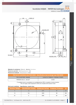
SCAMBIATORI DI CALORE
HEAT EXCHANGERS
AND PRESSURE VESSEL
FLOVEX S.p.A.
20064 GORGONZOLA (MI) - ITALY
Via C. Porta, 5/11
Tel.: +39 02 9512611 r.a. - Fax: +39 02 95126139
e-mail: [email protected] - www.flovex.it
Profilo
aziendale
FLOVEX S.p.A. Apparecchi per la soluzione di ogni problema di scambio termico
Fin dalla sua fondazione, 1977,
la FLOVEX ha operato con
professionalità nel campo degli
scambiatori di calore. Nel mondo stanno funzionando più di
100.000 impianti che utiizzano
scambiatori FLOVEX. Una forte
tendenza a seguire le richieste
del mercato e dei Clienti ha
permesso a FLOVEX di espandersi durante gli anni sia in
Italia che in vari Paesi europei
distinguendosi per la sua alta
qualità (ISO 9001).
Particolare cura è posta nella progettazione termodinamica. La FLOVEX è membro
dell'Istituto Heat Transfer Research Inc.
(USA) ed utilizza le più sofisticate tecniche
di analisi per ottimizzare la scelta di ogni
tipo di scambiatore. La vasta gamma di
prodotti (scambiatori a fascio tubiero,
scambiatori ad aria, scambiatori a piastre,
condensatori, riscaldatori) consentono a
FLOVEX di soddisfare le esigenze di ogni
Cliente. Tutti gli scambiatori vengono
prodotti sia in versione standard FLOVEX,
sia secondo normative (TEMA, API, ecc.).
La sede amministrativa e lo stabilimento
della Flovex sono ubicati nell'immediato
hinterland milanese e precisamente a:
20064 GORGONZOLA (MI) - ITALY
Via C. Porta, 5/11
Tel. 02 9512611 - Fax 02 95126139
e-mail: [email protected]
www.flovex.it
Certificazioni
Dal 1993 stiamo adottando una
procedura di qualità, che soddisfa
i requisiti fissati nelle specifiche
ASME VIII e le cui regole sono
indicate nel relativo manuale.
Dal 1996 abbiamo incominciato a
sviluppare le procedure per la
qualifica aziendale secondo la
normativa UNI EN ISO 9001; tale
processo è terminato alla fine del
1998.
Speciali test e processi che non
possono essere svolti al nostro
interno ed altri, sono effettuati
presso appositi laboratori qualificati.
Dal 1999 siamo accreditati dalla
American Society of Mechanical
Engineers (ASME) a costruire e
stampare i nostri prodotti con la
famosa "U" riconosciuta in tutto il
mondo.
FLOVEX S.p.A.
20064 GORGONZOLA
(MI) - ITALY
Via C. Porta, 5/11
Tel. 02 9512611
Fax 02 95126139
e-mail: [email protected]
www.flovex.it
ASME
Certifications
WHAT IS ASME?
Founded in 1880 as the American
Society of Mechanical Engineers,
today ASME International is a
nonprofit educational and technical
organization serving a worldwide
membership of 125,000:
conducts one of the world's largest
technical publishing operations.
holds some 30 technical
conferences and 200 professional
development courses each year
sets many industrial and
manufacturing standards.
The work of the Society is
performed by its member-elected
Board of Governors and through its
five Councils, 44 Boards and
hundreds of Committees in 13
regions throughout the world. There
are some 400 sections serving
ASME's worldwide membership.
More than 90 countries use the 600
codes and standards fixed by ASME
International. Development of these
internationally accepted codes
conforms to the procedures set by
the American National Standards
Institute (ANSI - www.ansi.org).
These standards are authoritative
technical guidelines for promoting
safety, reliability, productivity and
efficiency in many types of industry.
These guidelines often become
means for satisfying both
commercial and government
procurement requirements.
WHAT IS THE ASME Code?
One of the most important sections
refers to the ASME Boiler and
Pressure Vessel Code (Flovex field
of operations), Section VIII, Division
1, that gives a detailed list of the
standards used in the design,
manufacture and testing of pressure
vessels.
WHAT IS A "U" Stamp?
The American Society of
Mechanical Engineers (ASME www.asme.org) certifies a company
and plant location as being capable
of designing and manufacturing
pressure vessels in line with the
standards of the ASME Code
(specified above).
Once this is achieved, the company
is authorized by ASME to place a
"U" on the codeplates certifying that
the particular vessel has met the
requirements of the ASME Code.
This certification is verified by a
third-party or outside inspection
agency and is renewed every three
years; it isd also audited on a yearly
basis. The ASME certification
issued to Flovex provides a level of
assurance to all current or potential
customers that FLOVEX adheres to
the established and internationally
accepted standard.
FLOVEX S.p.A. has the Certificate
Number: 31,030 (MAY 20, 1999)
Prodotti
standard
I TUBI ALETTATI
Nella progettazione degli
scambiatori di calore le possibili combinazioni di materiali e
soluzioni tecniche sono praticamente inesauribili. Il buon
funzionamento e la durata di
uno scambiatore sono legati
ad una scelta mirata al tipo di
applicazione.
L'impiego di TUBI ALETTATI
permette dimensioni di ingombro più contenute e quindi un
minore consumo di acqua a
parità di efficienza. Nel confronto con gli scambiatori di
tipo tradizionale di piccolo
diametro e con gli scambiatori
a piastre, l'impiego del tubo
alettato si è dimostrato spesso
una soluzione vincente sia per
i costi che per gli ingombri e
con resistenza allo
sporcamento (durata dello
scambiatore) anche 3 volte
maggiore.
Per gli scambiatori di tipo industriale la FLOVEX ha voluto ricercare il massimo rapporto tra efficienza e robustezza, sono quindi
impiegati per tutti gli scambiatori, nella esecuzione base, TUBI
AD ALETTATURA INTEGRALE. Essi sono ottenuti dal tubo liscio
mediante deformazione plastica dopo la trafilatura.
Tubi alettati per
scambiatori di calore
Nello stesso ingombro c’è una
superficie 4 volte maggiore.
La pluriennale esperienza FLOVEX di tubi alettati in rame e sue
leghe consente di affiancare alla esecuzione base, quando particolari condizioni lo impongono, un'ampia gamma di materiali a
nobiltà crescente in versione liscia oppure alettata.
Prodotti
standard
Scambiatore di grande versatilità compatto efficiente economico. Grande efficienza
e versalità. Completa gamma disponibile a
stock. Impieghi di piccola e media
potenzialità, con portate olio fino a
200 lt/min. Fascio ad alettatura integrale
corpo in lega leggera con coperchi dello
stesso materiale o di resina rinforzata.
Completa gamma di scambiatori standard
a piastra tubiera fissa in diverse configurazioni di forma e/o materiali. Impieghi di
media e alta potenzialità per
oleodinamica, chimica, recupero
energetico ecc. Versione base con corpo
in acciaio al carbonio, fascio di rame ad
alettatura integrale e coperchi in ghisa.
Realizzazione a fascio tubiero estraibile
anche per potenzialità molto elevate.
Completa possibilità di pulizia durante la
manutenzione Unità predisegnate con
componenti quasi tutti a stock per portate
anche molto elevate.
Scambiatore a testa flottante di contenute
dimensioni per risolvere i problemi di ALTA
TEMPERATURA laddove non si può
utilizzare la costruzione più semplice con
tubi a U (KE) e le portate sono basse.
Componenti standard da stock.
Prodotti
standard
Scambiatori realizzati in accordo alle
norme internazionali TEMA-ASME e
TEMA "U" STAMPED. Ampia scelta dei
materiali e delle configurazioni. Coperchi
flangiati. Collaudi certificati da LL.RR. - BV
- DNV ecc.
Scambiatori di calore in esecuzione
duplex, con valvole deviatrici a 3 vie.
Progettazione e costruzione in accordo
con le norme TEMA - ASME - API.
Scambiatori per montaggio in serbatoio ed
esterno. Totale assorbimento dello
STRESS TERMICO mediante il fascio a
spirale flottante ottenuto con tubo di rame
alettato ad alta efficienza.
Resistenze in ferro per riscaldare olio
(max ISO VG 68).
Potenza resa circa 2.5 W/cm2 a 230-400V;
altre tensioni e viscosità a richiesta. Coperchio di protezione dei collegamenti in
gomma con protezione IP 54. Versione da
inserire direttamente nel serbatoio oppure
in un corpo con uno o più elementi riscaldanti.
Prodotti
standard
Scambiatori aria/olio con massa radiante
in alluminio. Prodotti in una completa serie
di modelli con differenti potenzialità e
motorizzazioni. Possibili esecuzioni speciali con motori antideflagranti.
Scambiatori con raffreddamento ad aria
per fluidi e gas in pressione fino a 20 barG
di esercizio. Costruzione standard con
alette in alluminio e tubi di rame. Completa gamma disponibile da stock. Realizzazioni speciali di grandi unità multiple del
modulo standard.
Scambiatori con raffreddamento ad aria
per ambienti pericolosi e in applicazioni
gravose. Realizzazione secondo norme
ASME - API con tubi lisci o alettati in
acciaio rame, alluminio, inox, ecc.
Motorizzazioni in accordo alle norme
internazionali
DF X
Filtri per la pulizia dell’olio da
lubrificazione in accordo alle norme
internazionali ASME VIII Div. 1 e API 614.
Collaudi certificati da Enti terzi e
stampigliatura U-STAMP.
Cartucce filtro dei più qualificati costruttori
Dettagli tecnici
ST80 COMPATTO - EFFICIENTE - ECONOMICO
1
2
3
4
5
6
7
8
9
10
Controflange SAE per un più facile montaggio
Targa di identificazione, ogni scambiatore è collaudato
Tubi ad alettatura integrale
Connessioni filettate o flangiate, ampie dimensioni per minori cadute di pressione
Minor numero di tubi, maggiore facilità di pulizia
Sistema di tenuta brevettato "Elastic Joint" contro shock termici e colpi d'ariete
Piastra tubiera in INOX 316 per qualsiasi problema di acqua
Piedi di fissaggio posizionati a 90 gradi
Coperchi in materiale sintetico rinforzato, resistenti alla corrosione
Bocche di collegamento con bussole incorporate nel coperchio
Dettagli tecnici
EM
WE
BP
TW
Tipica piastra tubiera fissa
1 Corpo
2 Piastra tubiera
3 Coperchio
4 Guarnizione
5 Tubo di scambio
Tipica piastra tubiera flottante
1 Corpo
2 Anello
3 Anello spia
4 Coperchio
5 Guarnizioni
6 Piastra tubiera
7 Tubo scambio
Tipica piastra tubiera flottante
1 Corpo
2 Anello
3 Guarnizione
4 Piastra tubiera
5 Coperchio
6 Tubo scambio
Coperchi flangiati
e/o filettati in carbon steel
o inox. Costruzione anche
standard FLOVEX
Prodotti
speciali
Scambiatore U-stamp con giunto
dilatatore
Condensatore
vapore
manicotti
Scambiatori per le tenute in accordo
alle API 682
Polmone smorzatore per alta pressione
collaudo U-stamp
ed Ente terzo
Condensatore
vapore
manicotti
con
certificazione
navale
Recuperatore ad aria per fumi di processo
Prodotti
speciali
Condensatore
vapore
manicotti
Filtro duplex
per olio
Unità duplex
di scambiatori
Batteria di
riscaldamento
olio
a due stadi
con motore
in stand-by
Batteria di riscaldamento aria a due stadi
con vapore
Sistemi
di calcolo
Tutte le richieste d'offerta vengono sviluppate
dal nostro ufficio tecnico mediante un software
interno sviluppato e collaudato negli anni. Per
applicazioni critiche o contenenti gas si utilizza
il software dell'Heat Transfer Research
Incorporated (HTRI www.htri-net.com) di cui
siamo membri e grazie al cui supporto siamo
costantemente informati sullo stato dell'arte
dello scambio termico.
Tutti gli apparecchi standard sono predisegnati
e costruiti rapidamente con componenti disponibili a magazzino. Per gli scambiatori TEMA ,
partendo dalla specifica termodinamica, si ottiene il design finale con i più moderni sistemi
CAD permettendo di ottenere veloci approvazioni mediante l'invio per e-mail di disegni
costruttivi.
Infine, gli scambiatori vengono assemblati da
saldatori certificati ASME e subiscono tutti i
controlli non distruttivi imposti dal codice e concordati nell'ordine, nonché un test idraulico.
Prima di apporre la targa FLOVEX viene fatta
un ulteriore ispezione finale ed in accordo al
nostro sistema di gestione della qualità ogni
componente viene approvato.
Referenze
ABB
ANSALDO
ARABIAN GULF
DALMINE
DANIELI
DROPSA
ENEL
EUROTECNICA
FINCANTIERI
FLUOR DANIEL-PHILLIPS
INNSE
LUCCHINI
NEUMANN & ESSER
NUOVO PIGNONE
OLAER INDUSTRIES
PIANIMPIANTI
REPCO
SIAD
SULZER-DE PRETTO
TECHINT
TERMOKIMIK
TOSCO REFINING COMP.
WORTINGTON
Organizzazione
commerciale
italiana
Piemonte - Valle d’Aosta
FLUID TECHNOLOGY
Via Reduzzi, 9 - 10134 TORINO
Tel. 011-3190588 - Fax 011-3186822
E-mail: [email protected]
Lombardia
SELETEC
Via L. Da Vinci, 21E
20060 CASSINA DE' PECCHI - Milano
Tel. 02-95341336 - Fax 02-95341352
E-mail: [email protected]
Veneto - Trentino Alto Adige
TECNOLOGIE E SERVIZI
Via Roma, 20/A
31032 CASALE SUL SILO - TV
Tel. 0422-820920 - Fax 0422-821131
E-mail: [email protected]
Friuli Venezia Giulia
TECNOFLUID
Via Rossetti, 59 - 34142 TRIESTE
Tel. 040-662690 - Fax 040-362940
E-mail: [email protected]
Liguria
MEDITER sas
Via Piave, 7 - 16145 GENOVA
Tel. 010-369041 - Fax 010-3690459
E-mail: [email protected]
Emilia Romagna
BENVENUTI RAPPRESENTANZE
Via G. Rivani, 33 - 40138 BOLOGNA
Tel. 051-533007 - Fax 051-6010482
E-mail: [email protected]
Campania
ATEC sas
Via G. Nicotera, 10 - 80132 NAPOLI
Tel. 0347-8632765 - Fax 081-7284922
E-mail: [email protected]
Organizzazione
commerciale
estero
D
GERMANIA - WIDLER GmbH Neusser Str. 13 - 41061 MONCHENGLADBACH 1
Tel. 0049/2161/960287 - Fax 0049/2161/960289
E
SPAGNA - OLAER OILTECH IBERICA S.A. Travesia Industrial 29 - L’HOSPITALET DE LLOBREGAT - 08907 BARCELLONA Tel. 0034/93/3361412 - Fax 0034/93/3357186
F
FRANCIA - OLAER INDUSTRIES S.A. - 16 Rue De Seine - 97200 COLOMBES
Tel. 0033/1/41191700 - Fax 0033/1/41191720
CH
SVIZZERA - OLAER SCHWEIZ A.G. - Bonnstrasse 3 - 3186 DUDINGEN
Tel. 0041/26/4927000 - Fax 0041/26/4927070
A
AUSTRIA - OLAER SPEICHER TECHNIK GESELLSCHAFT GmbH Haiderstrasse 38 - 4052 ANSFELDEN Tel. 0043/7229/80306 - Fax 0043/7229/8030621
B
BELGIO - S.A. OLAER BENELUX N.V. - Doornveld 4 - 1731 ZELLIK
Tel. 0032/2/4661515 - Fax 0032/2/4661624
NL
OLANDA - OLAER NEDERLAND B.V. - P.O. BOX 75 - 4840 AB PRINSENBEEK
Tel. 0031/76/5412453 - Fax 0031/76/5411502
GB
INGHILTERRA - OLAER FAWCETT CHRISTIE HYDRAULICS Ltd.
Sandycroft Industrial Estate Chester Road Sandycroft - DEESIDE CLWYD CH5 2QP
Tel. 0044/1244/535515 - Fax 0044/1244/533002
NZ
AUSTRALIA - OLAER FAWCETT CHRISTIE HYDRAULICS Ltd. - 13 Boola Place
- CROMER NSW 2099 - Tel. 0061/2/99816888 - Fax 0061/2/99816144
CZ
REP. CECA - OLAER CZ s.r.o. - Videnska 125 - 63900 BRNO
Tel. 00420/5/47125601 - Fax 00420/5/47125600
GR
GRECIA - INDUSTRIAL TECHNOLOGIES S.A. - 33 Ioanninon Str. - GR 104 44 ATENE
Tel. 0030/1/5151723 - Fax 0030/1/5151725
SCAMBIATORI
HEAT EXCHANGERS
FLOVEX S.p.A.
Via C. Porta, 5/11 - 20064 GORGONZOLA (MI) - ITALY
Tel.: + 39 02 9512611 r.a. - Fax: +39 02 95126139
e-mail: [email protected] - www.flovex.it
FLOVEX S.p.A. - 20064 GORGONZOLA (MI) - Via C. PORTA 5/11 - TEL. 02-9512611 - FAX 02-95126139
SHEET 2001.
Dimensioni e caratteristiche non impegnative. Tolleranze secondo norme. - Dimensions and characteristics of the catalogue are subject to change without notice. Clearances according to international standards.
SCHEDE TECNICHE PRODOTTI
PRODUCTS DATA SHEETS
La FLOVEX nello stabilimento di Gorgonzola, alle porte
dell’hinterland di Milano, realizza, con le più aggiornate
tecnologie e materiali, esclusivamente apparecchi per la
soluzione di ogni problema di scambio termico.
In the factory at Gorgonzola, just outside the doors of Milan,
FLOVEX solves almost all problems of heat transfer, using
uptodate tecnologies and materials.
Malpensa
A9 Como
Chiasso - CH
FLOVEX S.p.A.
Via C. Porta, 5/11
20064 GORGONZOLA (MI) - ITALY
Tel.: +39 02 9512611 r.a. - Fax: +39 02 95126139
E-mail: [email protected] - www.flovex.it
Lecco
o
ergam
A4 B nezia
Ve
o
gam
Agrate
Ber
Monza
MM
GERMANIA - WIDLER GmbH
Neusser Str. 13 - 41061 MONCHENGLADBACH 1
Tel. 0049/2161/960287 - Fax 0049/2161/960289
FF.SS.
MILANO
Melzo
Venezia
Linate
Melegnano
a
gn
lo
Bo
SPAGNA - OLAER OILTECH IBERICA S.A.
Travesia Industrial 29 - L’HOSPITALET DE LLOBREGAT
08907 BARCELLONA
Tel. 0034/93/3361412 - Fax 0034/93/3357186
A4 Torino
A7
Ge
nov
a
ORGANIZZAZIONE COMMERCIALE EUROPEA
Europe sales organization
FLOVEX
Gorgonzola
A1
FRANCIA - OLAER INDUSTRIES S.A.
16 Rue De Seine - 97200 COLOMBES
Tel. 0033/1/41191700 - Fax 0033/1/41191720
SVIZZERA - OLAER SCHWEIZ A.G.
Bonnstrasse 3 - 3186 DUDINGEN
Tel. 0041/26/4927000 - Fax 0041/26/4927070
AUSTRIA
OLAER SPEICHER TECHNIK GESELLSCHAFT GmbH
Haiderstrasse 38 - 4052 ANSFELDEN
Tel. 0043/7229/80306 - Fax 0043/7229/8030621
BELGIO - S.A. OLAER BENELUX N.V.
Doornveld 4 - 1731 ZELLIK
Tel. 0032/2/4661515 - Fax 0032/2/4661624
OLANDA - OLAER NEDERLAND B.V.
P.O. BOX 75 - 4840 AB PRINSENBEEK
Tel. 0031/76/5412453 - Fax 0031/76/5411502
INGHILTERRA
OLAER FAWCETT CHRISTIE HYDRAULICS Ltd.
Sandycroft Industrial Estate Chester Road Sandycroft
DEESIDE CLWYD CH5 2QP
Tel. 0044/1244/535515 - Fax 0044/1244/533002
AUSTRALIA OLAER FAWCETT CHRISTIE HYDRAULICS Ltd.
13 Boola Place - CROMER NSW 2099
Tel. 0061/2/99816888 - Fax 0061/2/99816144
PEP. CECA - OLAER CZ s.r.o.
Videnska 125 - 63900 BRNO
Tel. 00420/5/47125601 - Fax 00420/5/47125600
GRECIA - INDUSTRIAL TECHNOLOGIES S.A.
33 Ioanninon Str. - GR 104 44 ATENE
Tel. 0030/1/5151723 - Fax 0030/1/5151725
FLOVEX S.p.A. - 20064 GORGONZOLA (MI) - Via C. PORTA 5/11 - TEL. 02-9512611 - FAX 02-95126139
SHEET 2001.
Dimensioni e caratteristiche non impegnative. Tolleranze secondo norme. - Dimensions and characteristics of the catalogue are subject to change without notice. Clearances according to international standards.
SCAMBIATORI
HEAT EXCHANGERS
SHEET 2001.
Dimensioni e caratteristiche non impegnative. Tolleranze secondo norme. - Dimensions and characteristics of the catalogue are subject to change without notice. Clearances according to international standards.
SCAMBIATORI
HEAT EXCHANGERS
FLOVEX S.p.A. - 20064 GORGONZOLA (MI) - Via C. PORTA 5/11 - TEL. 02-9512611 - FAX 02-95126139
F
S
in dalla sua fondazione, 1977, la Flovex
ha operato con professionalità nel campo
degli scambiatori di calore.
ince its foundation 20 years ago, Flovex
has been operating with authority in the field
of heat exchangers.
Nel Mondo stanno funzionando più di
100.000 impianti con scambiatori Flovex.
More than 100.000 Flovex heat exchangers
are working in the world.
Una forte tendenza a seguire le richieste
del mercato e dei clienti ha permesso a Flovex
di espandersi durante gli anni sia in Italia che
in vari Paesi europei distinguendosi per la sua
alta qualità (ISO 9001).
A strong orientation to the market and to
customer requirements has allowed Flovex to
expand over the years both on the national
territory and in various European countries
with a continuous track record of high quality
(ISO 9001).
Particolare cura è posta nello sviluppo
della progettazione termodinamica. La Flovex
è membro dell'Istituto Heat Transfer Research
Inc. (USA) ed utilizza le più sofisticate
tecniche di analisi per ottimizzare la scelta di
ogni tipo di scambiatore.
Particulary care is taken in developping the
thermodynamic project. Flovex is a member
of Heat Transfer Research Inc. (USA) and
employs the most advanced instruments to
make the best choise of any type of coolers.
La vasta gamma di prodotti (scambiatori a
fascio tubiero, scambiatori ad aria, scambiatori
a piastre, condensatori, riscaldatori, filtri per olio)
consentono a Flovex di soddisfare le esigenze
di ogni Cliente. Tutti gli scambiatori vengono
prodotti sia in versione standard Flovex, sia
secondo normative (PED, TEMA, API, ecc).
The wide range of manufactured products
(shell and tube heat exchangers, fan coolers,
plate coolers, condensers, heaters, oil filters)
puts Flovex in the position to meet the heat
exchange needs of almost every Customer.
All products are manufactured both in Flovex
own versions and in standard (PED, TEMA,
API, etc.) versions.
I dati indicati in questo catalogo non sono
impegnativi, e la Flovex allo scopo di migliorare la
propria produzione si riserva il diritto di apportare
modifiche in qualsiasi momento e senza alcun preavviso.
È vietata ogni riproduzione anche parziale delle
figure e testi senza nostra autorizzazione.
The information shown in this catalogue are not
binding and in order to improve production, Flovex
reserves the right to make any changement (including
sizes) considered necessary at anytime and without
previous notice.
Any reproduction (also partial) of figures and texts is
forbidden without our authorization.
SHEET 2001.
Dimensioni e caratteristiche non impegnative. Tolleranze secondo norme. - Dimensions and characteristics of the catalogue are subject to change without notice. Clearances according to international standards.
SCAMBIATORI
HEAT EXCHANGERS
FLOVEX S.p.A. - 20064 GORGONZOLA (MI) - Via C. PORTA 5/11 - TEL. 02-9512611 - FAX 02-95126139
SCAMBIATORI
HEAT EXCHANGERS
SCAMBIATORI DI CALORE HEAT EXCHANGERS
Scambiatore standard. Grande efficienza e versalità. Completa gamma disponibile a stock.
Impieghi di piccola e media potenzialità, con portate olio fino a 200 lt. Corpo in lega leggera.
Fascio ad alettatura integrale.
Standard exchanger with great versatility and efficiency. All models ready on stock. Used for
small and medium cooling capacity, oilflow up to 200 (lit/’). ShelI in light alloy integrally
finned tubes.
EM
Completa gamma di scambiatori in diverse composizioni di forma e materiali. Impieghi di
media e alta potenzialità per oleodinamica, chimica, recupero energetico ecc. Corpo in acciaio al carbonio. Fascio ad alettatura integrale.
Medium and high cooling capacity extremely rugged construction, almost all combination of
materials gives versatility to use this type of exchanger from hydraulics, chemicals, to energy
saving. Standard with carbon steel shell, integrally finned tubes.
WE
Realizzazione a fascio tubiero estraibile anche per potenzialità molto elevate. Unità predisegnate
con componenti a stock. Portate oltre 500 (Iit/’) e superfici di 1000 m2 e oltre.
Pull-out bundle type exchanger of infinite combinations of materials, practically no limits in
cooling capacity, most components on stock. Flowrates over 500 (lit/’) cooling surface to
1000 m2 and over.
FC
Scambiatori per montaggio in serbatoio ed esterno. Totale assorbimento dello STRESS
TERMICO mediante il fascio a spirale flottante.
lntegrally finned spiral bundles to withstand THERMAL SHOCK, possibility to use outside or
inside the tank.
LT
Scambiatori con raffreddamento ad aria per fluidi e gas in pressione fino a 20 (Bar) di esercizio. Completa gamma disponibile da stock.
Realizzazioni speciali di grandi unità multiple del modulo standard.
Aircooled units for liquids and gasses up to 20 (Bar) of pressure. Complete range of standard
coolers on stock. Special big units made to calculation due to modular system.
BP
Scambiatore a testa flottante per risolvere problemi di ALTA TEMPERATURA. Componenti
standard da stock.
Small floating headed exchanger specially designed to handle HIGH TEMPERATURES.
Standardised components from stock.
TW
E
AND
CM
Scambiatori realizzati in accordo alle norme internazionali TEMA-ASME, e PED. Ampia scelta
dei materiali e delle configurazioni. Collaudi certificati da LL.RR. - BV - NV ecc.
Whole range of exchangers built according to A.S.M. E. / T .E.M.A. e PED codes. Materials
according to prescriptions, to fluids. Certificates, welders qualifications, according to LL.RR.,
BV, NV, etc.
KS
Scambiatori con raffreddamento ad aria per ambienti pericolosi e in applicazioni gravose.
Realizzazione secondo norme con tubi alettati in rame, alluminio, inox, titanio ecc.
Heavy duty aircooled exchangers to suite most codes, flameproof and hazardous aplications.
Made with bare or finned tubes. Materials as carbon steel, copper alloys, stainless or light
alloy to suite most prescriptions.
FLOVEX S.p.A. - 20064 GORGONZOLA (MI) - Via C. PORTA 5/11 - TEL. 02-9512611 - FAX 02-95126139
SHEET 2001.100
Dimensioni e caratteristiche non impegnative. Tolleranze secondo norme. - Dimensions and characteristics of the catalogue are subject to change without notice. Clearances according to international standards.
ST
SCAMBIATORI
HEAT EXCHANGERS
ST 80
Dimensioni e caratteristiche non impegnative. Tolleranze secondo norme. - Dimensions and characteristics of the catalogue are subject to change without notice. Clearances according to international standards.
• Compatto • Efficiente • Economico
• Solid • Efficient • Cheap
Controflange SAE
per un più facile montaggio
SAE counterflanges for easier
pipe connection
Connessioni filettate o flangiate.
Ampie dimensioni per minori cadute di pressione
Targa di identificazione,
ogni scambiatore è collaudato
Threaded or flanged connections oversized
to give less pressure drop at highest flow rates
Minor numero di tubi,
maggiore facilità
di pulizia
Less number of
tubes, easier
maintenance
Nameplate of identification, each
exchanger is tested
Tubi ad alettatura integrale.
Più efficienza, minor consumo
Integrally finned tubes.
More efficience, less water
Sistema di tenuta brevettato con “Elastic joint”
contro shock termici e colpi d’ariete
Patented “elastic joint” inbetween hubs &
shellpipe to withstand both thermal shock and
pressure hammering
Piastra tubiera in INOX 316 per qualsiasi
problema di acqua
Stainless AISI 316 tubesheets to
withstand most waterconditions
Bocche di collegamento con bussole
incorporate nel coperchio
Piedi di fissaggio
posizionati su 90°
Inserted metallic connections
in front cover
Coperchi in materiale sintetico rinforzato,
resistenti alla corrosione
Rotable supporting
feet adaptable on site
SHEET 2001.
SHEET 2001.101
Corrosion resistant reinforced
syntetic covers
FLOVEX S.p.A. - 20064 GORGONZOLA (MI) - Via C. PORTA 5/11 - TEL. 02-9512611 - FAX 02-95126139
SCAMBIATORI
DI CALORE FLOVEX
HEAT EXCHANGERS
BY FLOVEX
Nella progettazione degli scambiatori di calore le possibili combinazioni di materiali e soluzioni tecniche sono
praticamente inesauribili. Il buon funzionamento e la
durata di uno scambiatore sono legati ad una scelta
mirata al tipo di applicazione. Per gli scambiatori di tipo
industriale la Flovex ha voluto ricercare il massimo rapporto tra efficienza e robustezza, sono quindi impiegati
per tutti gli scambiatori, nella esecuzione base, TUBI
AD ALETTATURA INTEGRALE.
In projecting a good heat exchanger to suit the
applications infinite combinations of materials and
technical solutions can be used. Good performance and
long lasting life are strictly related to this fact.
For industrial applications in Flovex a deep research
has been made to get the best performance together
with rugged longlasting construction. In fact as standard,
the choice of the INTEGRALLY FINNED TUBES has
been adopted. These tubes are rolled from bare tubes
by plastic deformation; with this operation the surface
increases about four times, during this procedure
increases the resistance of the tube to corrosion also.
The exchanger with such tubes wiIl have smaller size,
higher velocities of the water inside the tubes, this means
using less water, and less fouling due to calcium and
other deposits: it means longher life.
Using INTEGRALLY FINNED TUBES (with outside
diameter of at least 16 (mm) and over), against other
exchangers using small bare tubes, or plate exchangers,
is many times a winning choice as price, sometimes as
size, and all times as resistance against fouling
Essi sono ottenuti dal tubo liscio mediante deformazione plastica: questa lavorazione ne migliora anche le
caratteristiche fisico-meccaniche e la resistenza alla
corrosione elettrochimica.
L'impiego di TUBI ALETTATI oltre a rendere possibili
dimensioni di ingombro più contenute, implica molteplici vantaggi. Grazie ai più favorevoli rapporti di velocità
e coefficienti di scambio, permette un MINORE consumo di acqua, alta affidabilità e resistenza allo
sporcamento.
Nel confronto con scambiatori di tubo tradizionale di piccolo diametro e con gli scambiatori a piastre, l'impiego
del TUBO ALETTATO si è dimostrato soluzione vincente sia per costi, ingombri e con resistenza allo
sporcamento (durata dello scambiatore) anche 3 volte
maggiore.
La pluriennale esperienza Flovex nell'impiego di tubi
alettati in rame e sue leghe consente di affiancare alla
esecuzione base, quando particolari condizioni lo impongono, una ampia gamma di opzioni con tubi INOXFERROMONEL nelle tradizionali esecuzioni sia liscie
che ad alettatura integrale.
GARANZIA
La garanzia ha validità di 2 mesi dalla data di consegna. La Flovex si impegna a sostituire o riparare i prodotti che risultino difettosi, purché non siano stati manomessi e siano stati correttamente impiegati. Le prestazioni in garanzia vengono effettuate solo ed esclusivamente f.co Flovex. È esclusa da ogni forma di garanzia il deterioramento provocato da sporcamento, corrosione, erosione, corpi estranei, vibrazioni e altre cause
similari.
(the average time inbetween necessary cleaning can
be three times longer..!).
After many years of experience by Flovex using integrally
finned tubes in copper and copper alloys, as optional to
particular need or to customers requirement we can
deliver with STAINLESS, CARBON STEEL, MONEL and
lot's of other materials, finned or bare tubes; projecting
also many different types of exchangers not shown in
our standard catalogue.
GUARANTEE
Flovex guarantee shall extend for a period of twelve (12)
months after the shipping date. Flovex shall repair or
replace f.o.b. own plant any parts proven to be defective
within the guarantee period. Finished materials and
accessories purchased from other manufacturers,
including tubes, are warranted only to the extent of the
original manufacturer's warranty. Flovex does not assume any responsibility for deterioration of any part or parts
of the equipment due to corrosion, erosion, flow induced
tube vibration, or any other causes.
FLOVEX S.p.A. - 20064 GORGONZOLA (MI) - Via C. PORTA 5/11 - TEL. 02-9512611 - FAX 02-95126139
SHEET 2001.102
Dimensioni e caratteristiche non impegnative. Tolleranze secondo norme. - Dimensions and characteristics of the catalogue are subject to change without notice. Clearances according to international standards.
SCAMBIATORI
HEAT EXCHANGERS
Tubi alettati per scambiatori di calore
Finned tubes for heat exchangers
Fascio tubiero costruito con tubi di rame alettati
Tube bundle realized with copper finned tubes
Scambiatore tipo WE con fascio tubiero alettato
Exchanger WE type with finned tube bundle
Nello stesso ingombro c’é una
superficie 4 volte maggiore
In the same space the surface
increases about four time
SHEET 2001.
SHEET 2001.103
Dimensioni e caratteristiche non impegnative. Tolleranze secondo norme. - Dimensions and characteristics of the catalogue are subject to change without notice. Clearances according to international standards.
SCAMBIATORI
HEAT EXCHANGERS
FLOVEX S.p.A. - 20064 GORGONZOLA (MI) - Via C. PORTA 5/11 - TEL. 02-9512611 - FAX 02-95126139
SCAMBIATORI
HEAT EXCHANGERS
Solid - Efficient
Light alloy heat exchanger
CARATTERISTICHE GENERALI
Il Modello ST 80 è l'evoluzione di uno scambiatore di ormai
collaudata produzione: il risultato è un apparecchio che unisce
requisiti di efficienza termica, compattezza ed estrema
affidabilità.
Grazie al nuovo sistema di tenuta, brevettato, con interposizione
di un elemento elastico, lo scambiatore ST 80 garantisce eccezionale resistenza a shock termici e colpi d'ariete.
Particolare attenzione è stata posta al problema corrosione con
acque industriali. Lo scambiatore ST 80 dispone di PIASTRE
TUBIERE INOX AISI 316 in corpo unico con la testata in lega leggera.
I coperchi di ingresso ed inversione acqua sono realizzati in resine
plastiche rinforzate, resistenti alla corrosione ed alla pressione. L'ampia gamma di modelli è prevista sia nella versione “A” (per portate
medio basse) che nella versione “B” (per portate alte). Si raccomanda di completare sempre la sigla con l'indice di portata che
viene stampigliato anche sulla testata anteriore oltre che sulla targa.
A garanzia di un elevato standard produttivo ogni scambiatore
viene sottoposto ad un “controllo qualità” e ad una prova in
pressione prima di essere posto in commercio.
GENERAL CHARACTERISTICS
The model ST 80 is the result of evolution of this exchanger,
giving the most as thermal efficiency, compactness, combined
with extreme ruggedness.
Using our patented system of elastic sealing, the ST 80 has
become exceptionally safe against thermal shock and
waterhammering.
Particular attention has been taken to one of the greatest
problems as corrosion due to industrial water.
The exchanger ST 80 has hight alloy hubs but with STAINLESS
AISI 316 TUBESHEETS rolled permanently to hubs.
The covers waterside are made in reinforced plastic material
to withstand corrosion, and waterpressure.
All range of models have been divided into two types according
to oilflow. Tipe "A" for low/medium oilflow, type "B" to high oilflow.
Our raccomandation all times, to complete signature of
exchanger (letter "A" or "B" to be found on label and stamped
permanently on hubs of each exchanger).
To give more guarantee, each exchanger passes a "quality
control" and a hydraulic test before leaving our workshop.
CARATTERISTICHE COSTRUTTIVE
CONSTRUCTION
FASCIO TUBIERO
Sono impiegati tubi rettilinei ad ALETTATURA INTEGRALE ad
alto rendimento, in rame passivato, mandrinati alle piastre
tubiere. L'alta qualità dei materiali impiegati e le moderne tecniche di lavorazione garantiscono massima robustezza anche
in presenza di vibrazioni e colpi d'ariete.
TUBE BUNDLE
INTEGRALLY FINNED, chemically passivated, straight copper
tubes rolled into the tubesheets, enshure most efficiency. The
high quality of material of the tubes (made with most modern
procedure, tested one-by one) will give our exchanger extra
strenght even under vibration or hammering from circuit.
TESTATE
Sono stampate in lega leggera di “Anticorodal” e comprendono sia le piastre tubiere in inox AISI 316, che le connessioni
lato olio, SAE Ø 11/2”, ampiamente dimensionate per diminuire
le cadute di pressione.
Il piano flangia con fori passanti consente la possibilità di collegamento con flange SAE. Sono disponibili in opzione anche
attacchi filettati GAS o controflange SAE.
HUBS
Pressed in light alloy, type "ANTICORODAL", in one piece with
tubesheet in STAINLESS AISI 316 and oilside connection type
SAE to reduce velocity/pressure drop in inlet/outlet even at
higher flow.
As optional: threaded 11/2” B.S.P. connections, or SAE type
counterflanges.
MANTELLO
Il mantello è costituito da un tubo estruso, calibrato, in lega
leggera. Esso è unito alla testata mediante una guarnizione
“OR” permanentemente serrata nello scambiatore.
SHELL
Cold drawn, calibrated, extruded light alloy tube, at both
extremity one hub, sealed permanently "O" ring.
COPERCHI
Alle testate sono fissati i coperchi anteriore e posteriore, realizzati in materiale plastico, rinforzato in fibra di vetro con ottima resistenza alla pressione ed alla corrosione. Le connessioni acqua prevedono attacchi Ø 1/2” BSP mediante manicotti
filettati in acciaio stampati assieme ai coperchi.
Per evitare danneggiamenti, in fase di montaggio, si raccomanda l'impiego di raccordi con filettatura cilindrica e guarnizione piana, o sigillanti tipo “Loctite”. Coppia massima di
serraggio applicabile = 8 (Kgm). Sono comunque sempre disponibili a richiesta anche i coperchi in lega leggera con attacchi Ø 3/4” BSP.
COVER
Plastic material, glass fiber reinforced with 1/2" B.S.P.
connection in carbon steel stamped in one piece, to give
exceptional resistance against corrosion, combined with good
mechanical strenght.
In order to avoid damages, we raccomend the use of nipples
with cylindrical thread combined with flat gaskets or the use of
"Locktite" type sigillant materials. Maximum allowable torque
couple about 8 (Kgm) should be enough. To special request
are all times available light alloy covers with connections
Ø 3/4" BSP.
FLOVEX S.p.A. - 20064 GORGONZOLA (MI) - Via C. PORTA 5/11 - TEL. 02-9512611 - FAX 02-95126139
SHEET 2001.104
Dimensioni e caratteristiche non impegnative. Tolleranze secondo norme. - Dimensions and characteristics of the catalogue are subject to change without notice. Clearances according to international standards.
ST
COMPATTO - EFFICIENTE
SCAMBIATORE IN LEGA LEGGERA
DEFLETTORI
Realizzati in lamiera di acciaio con fori muniti di collare.
Si adattano con stretta tolleranza sia ai tubi che al mantello,
per ottenere la massima efficienza termica.
BAFFLES
Stamped in carbon steel, with lips around tubes and at outline,
to give: better clearances between tubes to baffles, shell to
baffles, for higher efficiency.
SUPPORTI DI FISSAGGIO
Realizzati in lamiera di acciaio stampata, sono posizionabili
sulle testate in diversi orientamenti, per facilitare l'installazione
dell'apparecchio.
FEET
Stamped in carbon steel, screwed to covers, with possibility of
multiple orientation to make installation easier.
MANUTENZIONE
Una corretta scelta tecnica ed adeguate portate dei fluidi sono
condizioni primarie per la “lunga vita” dello scambiatore. Per la
serie ST 80 è necessaria solo una pulizia periodica lato acqua.
Ciò si esegue facilmente senza dover depressurizzare il lato
mantello (olio) solo togliendo i coperchi. L'impiego di tubi rettilinei ad alettatura integrale fa si che si abbia un minor numero di
tubi robusti, di maggior diametro, rispetto agli scambiatori tradizionali rendendo quindi molto più agevole la pulizia interna tubi
(lato acqua) anche usando semplici scovoli. Si raccomanda di
porre attenzione nel posizionare le guarnizioni all'atto di rimontare i coperchi ed al giusto orientamento dei medesimi.
Vedi foglio “USO E MANUTENZIONE”.
MAINTENANCE
A correct selection by our performance curves and a correct
flowrange of fluids, will enshure long, trouble-free life to our
exchanger. Being mostly oilcoolers, our ST 80 will need cleaning
only tubeside (waterside) periodically.
This operation can be done without depressurising oilside only
taking off covers. The use of integrally finned tubes riduces the
actual number of tubes that combined with good wallthickness,
make even mechanical cleaning extremely easy against
traditional exchangers.
Our only recommandation is to take care of orientation of covers
and gaskets after maintenance.
See sheet "OPERATING AND MAINTENANCE".
GARANZIA
Ogni apparecchio è garantito contro difetti di fabbricazione o
dei materiali per la durata di mesi 12.
Nessuna garanzia contro la corrosione, vibrazioni eccessive,
colpi di ariete, incrostazioni ed errato montaggio.
WARRANTY
Each exchanger is guaranteed against defects of fabbrication
or the materials for 12 months. No guarantee will be hold against
corrosion, excessive vibrations, pressure hammering, calcium
deposits, and uncorrect installation.
A
B
K
425
285
305
8061
680
540
560
8076
830
692
712
8091
985
845
865
Per le curve di rendimento vedi tabella di selezione foglio 2001.134
For heat transfer curves see selection tables sheet 2001.134
TEMP. PROGETTO
design temperat.
°C
99
99
PRESS. PROGETTO
design pressure
Bar G
10
10
NUOVO - new
PRESSIONE PROVA
test pressure
Bar G
13
13
ST1 . 8035 . A40000
DATI DI PROGETTO
design data
ESEMPIO CODICE PRODOTTO
example of product code
105
TAGLIA
size
8035
VECCHIO - old
ST 8035 - A - 4
U.M. SHELL TUBES
FLOVEX S.p.A. - 20064 GORGONZOLA (MI) - Via C. PORTA 5/11 - TEL. 02-9512611 - FAX 02-95126139
SHEET 2001.
Dimensioni e caratteristiche non impegnative. Tolleranze secondo norme. - Dimensions and characteristics of the catalogue are subject to change without notice. Clearances according to international standards.
ST
SCAMBIATORI
HEAT EXCHANGERS
Fixed tubesheet
Straight tube - Type BEM or AEM
SCAMBIATORI
HEAT EXCHANGERS
TIPICA PIASTRA TUBIERA FISSA
Fixed tubesheet
1 - Corpo
2 - Piastra tubiera
3 - Coperchio
4 - Guarnizione
5 - Tubo scambio
shell
tubesheet
cover
gasket
tube
CARATTERISTICHE GENERALI
Scambiatori completamente standard, particolarmente indicati per impieghi gravosi anche per medie pressioni. La gamma
prevista è articolata in molteplici varianti che consentono di
risolvere qualsiasi problema di fluidi e di portata, anche con
elevate potenzialità di scambio.
Superfici di scambio da 0,3 m2 a 30 m2.
Di ciascun modello è prevista una versione "A" per portate medio basse, ed una versione "B" per portate alte.
GENERAL DESCRIPTION
Standard exchangers, particularly made for heavy duty ever
with medium pressure ranges. The composition can be made
with different choise of materials, all sort of combinations make
this type of exchangers versatile enough to solve any problem
of fluids, flows, even with high duty rating. Cooling surfaces
from 0.3 to 30 sq. mt.
For each standard model we've provided two types, “A” for Iow
flowrate, “B” for high flowrate.
COSTRUZIONE TIPO BASE EM1
CONSTRUCTION BASE TYPE EM1
FASCIO TUBIERO
Sono impiegati tubi rettilinei ad ALETTATURA INTEGRALE ad
alto rendimento, in rame passivato.
La mandrinatura dei tubi alle piastre garantisce massima robustezza anche in presenza di vibrazioni.
TUBE BUNDLE
Normally we use straight integrally finned "passivated" copper
tubes of extremely high efficiency.
The tubes are rolled into the tubesheets, to give the most rugged
construction even under vibration.
DEFLETTORI
Realizzati in lamiera stampata, con fori muniti di collare per
ridurre i trafilamenti, e aumentare l'efficenza e la robustezza.
BAFFLES
Punched from steel plate, with supporting lips for higher thermal
efficiency and more safety in case of vibration.
CORPO - PIASTRE TUBIERE
Completamente realizzati in acciaio al carbonio, con generosi
spessori, per resistere anche a severe applicazioni. Le connessioni vengono proposte sia con filettature BSP che con
flange UNI - SAE - ANSI.
SHELL & TUBESHEETS
Welded carbon steel construction, to give most rugged
exchanger, adeguate thicknesses for throuble free long life.
Shellside connections made also for customers requirement,
over the standard threated connections we propose flanges
(UNI, DIN, SAE, ANSI....).
COPERCHI
Esecuzione standard in ghisa ad alta resistenza, nelle versioni
a 2 e 4 vie.
COVERS
Standard exchangers with cast iron covers, in the 4 or 2 pass
versions.
VARIANTI
Il particolare tipo di costruzione consente di affiancare al modello base una larga gamma di alternative di materiali. Versione EL con piastre inox. Versione EX completamente inox. Molteplici possibilità di scelta di tubi in differenti tipi e materiali. Per
la definizione delle varianti vedi foglio composizione CODICE
PRODOTTO.
MATERIAL CHOISES
Over the standard carbon steel/copper combination we use:
Alumbrass, Stainless, carbon steel, copper/nichel as
tubematerial, while for shell & tubesheets using stainless steel
wiIl solve all possible problems.
Version EL with only the tubesheet in stainless steel; version
EX completely in stainless steel. For the complete range of
selection of tube types and materials, please see sheet of
composition of product code.
SIGLA DI IDENTIFICAZIONE
La sigla indica il diametro nominale in pollici, seguita dalla lunghezza in piedi ed eventuali frazioni.
Completare sempre la sigla con l'indice di portata (A = bassa
portata - B = alta portata) ed il numero di vie d'acqua
(es. EM1.8036.A2G000).
IDENTIFICATION THOROUGH OUR SIGNATURE:
First number in signature = shell diameter in inches, followed
by: the tubelenght in feet and eventual fractions. Must be
completed by letters: “A” or “B” (Iow-hight flowrate) and to finish,
the waterpass: EM1.8036.A2G000 = 8” diam. 3' 6" lenght, type
A with 2 pass!
GARANZIA
Ogni apparecchio è garantito contro difetti di fabbricazione o
dei materiali per un periodo di 12 mesi. Nessuna garanzia contro corrosione, incrostazioni, errato montaggio.
WARRANTY
Each exchanger is guaranteed and replaced for material or
fabricational defect for 12 months. No responsability wiIl be
taken against: corrosion, calcium deposits, or wrong installation.
FLOVEX S.p.A. - 20064 GORGONZOLA (MI) - Via C. PORTA 5/11 - TEL. 02-9512611 - FAX 02-95126139
SHEET 2001.106
Dimensioni e caratteristiche non impegnative. Tolleranze secondo norme. - Dimensions and characteristics of the catalogue are subject to change without notice. Clearances according to international standards.
EM
FASCIO FISSO
TUBI DIRITTI - TIPO BEM o AEM
FASCIO FISSO
ESEMPIO CODICE PRODOTTO
example of product code
VECCHIO - old
NUOVO - new
BEM 302 - A - 4
design temperat.
°C
99
99
PRESS. PROGETTO
design pressure
Bar G
10
10
PRESSIONE PROVA
test pressure
Bar G
13
13
DATI DI PROGETTO
design data
TEMP. PROGETTO
EM1 . 3020 . A4G000
VERNICIATO - Painting = RAL 5012
CONNESSIONI LATO CORPO
connections shell side
K ±3
TAGLIA
size
A
3012
3020
3030
3040
4012
4020
4030
4040
5012
5020
5030
5040
6020
6030
6040
6050
8030
8040
8050
8060
430
685
990
1295
435
690
995
1300
455
710
1015
1320
750
1055
1360
1665
1090
1395
1700
2005
B
250
500
805
1110
250
500
805
1110
240
490
795
1100
470
775
1080
1385
740
1045
1350
1655
C
D
H
90
83
65
95
108
90
115
140
105
145
168
125
175
219
180
4 vie
/ way
2 vie
/ way
309
564
869
1174
309
564
869
1174
313
568
873
1178
573
878
1183
1488
600
800
1000
1200
304
559
864
1169
333
588
893
1198
308
563
868
1173
580
885
1190
1495
600
800
1000
1200
Q
Eg
Ø S (GAS)
Type
A
B
U.M. SHELL TUBES
CONNESSIONI LATO TUBI
connections tube side
Ø S (FL.)
Type
4 vie / way
2 vie / way
N
ØT
GAS
N
ØT
GAS
130 DN25 DN40
25
3/4”
50
1”
140 DN25 DN40
35
3/4”
55
1”
Ef
A
B
✪
108
65
1”
11/2”
145
85
1”
11/2”
180
105
11/2”
2”
155 DN40 DN50
45
1”
76
11/2”
210
120
2”
2”
170 DN50 DN65
50
11/2”
86
2”
265
150
3”
3”
200 DN65 DN80 140
2”
130
3”
✪
✪
✪ Con connessione “Type B” - interasse bocche = B –15 mm
✪ With shellside port “Type B” - dimension = B –15 mm
LUNGHEZZA STANDARD - Sono disponibili scambiatori in
moduli di lunghezze intermedie (2.6 e 3.6) e superiori, non indicate a catalogo.
Dimensioni: sommare alle quote A-B-K del modello base le
lunghezze:
mezzo piede = 152 (mm);
1 piede = 305 (mm). Es.:
3026 A = 685 + 152 = 837 (mm).
6060 A = 1665 + 305 = 1970 (mm).
FLANGE STANDARD Ø F - La quota Ef è valida per flange:
Piane UNI - SO.ANSI - SAE 3000. Per flange Collare UNI W.N.
- W.N.ANSI, aggiungere 20 mm alla quota Ef.
DRENAGGIO - Per la serie 8” è previsto sia il drenaggio che lo
sfiato 1/2” GAS.
ANODI - Per le versioni marine (fascio Alumbrass B111 C687)
sono previsti due anodi di zinco, ispezionabili, Ø 3/8” sul coperchio posteriore.
STANDARD TUBELENGTH - In most cases we have
exchangers with superior and intermediate Ienghts (2’ 6”,
3’ 6”, etc...) not indicated in our catalogue.
To be able to find the measures, please sum te measures A-BK as follows:
6” = half ft. = 152 (mm);
1” = one ft. = 305 (mm). Ex.:
3026 A = 685 + 152 = 837 (mm).
6060 A = 1665 + 305 = 1970 (mm).
FLANGES - The measure of Ef is valid only for: flat UNI,
SO.ANSI & SAE flanges. For Welding neck type flanges, add
20 (mm) to Ef.
DRAIN - For the 8” series drain & went ot 1/2" GAS is used.
ANODES - For the marine exchangers we provide two zink
anodes, diam. 3/8” GAS threaded, inspectionable for
maintenance.
Per le curve di rendimento vedi tabella di selezione foglio
2001.134÷137
For heat transfer curves see selection tables sheet
2001.134÷137
FLOVEX S.p.A. - 20064 GORGONZOLA (MI) - Via C. PORTA 5/11 - TEL. 02-9512611 - FAX 02-95126139
SHEET 2001.
107
Dimensioni e caratteristiche non impegnative. Tolleranze secondo norme. - Dimensions and characteristics of the catalogue are subject to change without notice. Clearances according to international standards.
EM
SCAMBIATORI
HEAT EXCHANGERS
Fixed tubesheet
WE
FASCIO ESTRAIBILE
TUBI DIRITTI - TIPO BEW o AEW
SCAMBIATORI
HEAT EXCHANGERS
Removable bundle - Straight tube
Type BEW or AEW
1 - Corpo
2 - Anello
3 - Anello spia
4 - Coperchio
5 - Guarnizioni
6 - Piastra tubiera
7 - Tubo scambio
shell
main flange
retaining ring
cover
2 gaskets
tubesheet
tube
CARATTERISTICHE GENERALI
Scambiatori completamente standard con le medesime caratteristiche di impiego, meccaniche e dei materiali, della serie EM.
La codifica internazionale BEW indica uno scambiatore a fascio tubiero estraibile, con doppia guarnizione di tenuta sulla
piastra flottante, ed anello spia, per assicurare la massima
garanzia di completa separazione dei due fluidi, anche in caso
di rottura di guarnizioni.
Come per la serie EM, di ciascun modello è prevista la versione tipo "A" (bassa portata) e tipo "B" (alta portata).
La gamma è articolata in molteplici varianti che consentono di
risolvere qualsiasi problema di fluidi e di portata, anche con
elevate potenzialità di scambio.
GENERAL CHARACTERISTICS
Standard exchangers with same mechanical design, materials,
and use as EM type exchangers.
According to international coding “BEW” means pull-out bundle
with one fixed tubesheet, one floating tubesheet with two
gaskets separated by a telltale ring to avoid mixing of the two
fluids even with leaky or broken gaskets.
As for EM type exchangers the selection can be type “A” for
low flowrate shellside, and type “B” for high flowrate shellside.
The wide range of shellsize and tubelength makes this type of
exchangers able to solve most problems even for high dutyratings.
COSTRUZIONE TIPO BASE WE1
Vengono impiegati i medesimi componenti base della serie EM.
Fascio tubiero, deflettori, piastre e coperchi hanno le medesime caratteristiche e le medesime alternative dei materiali. Vengono realizzate solo le versioni a 2 e 1 via d'acqua.
CONSTRUCTION BASE TYPE WE1
Materials are the same as EM type. Tube bundle, baffles, covers
have same characteristics and alternatives as EM, while only
two or one pass waterside can be made.
SFILAMENTO DEL FASCIO - MANUTENZIONE
Prima di compiere qualsiasi operazione occorre togliere pressione ad entrambi i lati, mantello e tubi mentre per lo
scambiatore tipo EM a piastra fissa basta depressurizzare solo
il lato acqua.
Due guarnizioni piane sono interposte, per la tenuta, fra il coperchio, la piastra tubiera fissa e il mantello. Due guarnizioni
tipo OR, (BUNA o VITON secondo uso) sono poste a tenuta
della piastra posteriore, flottante, e l'anello spia.
Togliendo i coperchi e queste guarnizioni, si ha accesso al lato
tubi con possibilità di ispezione e pulizia meccanica mediante
scovoli.
Lo sfilamento del fascio per un eventuale flussaggio, avviene
dal lato anteriore, piastra fissa.
Occorre porre particolare cura nel manipolare il fascio per non
danneggiare i tubi e prevedere adeguati sostegni per evitare
la flessione dei fasci lunghi.
Sostituire sempre le guarnizioni dopo ogni smontaggio e controllare le sedi. Se necessario sostituire anche l'anello spia,
serrare i bulloni dei coperchi diagonalmente e con un tiro uniforme.
MAINTENANCE HINTS
Before unscrewing anything, pressure on both sides must be
releived, while in EM type shellside not need to be releived.
WE type exchanger have: on fixed tubesheet side two flat
gaskets on coverside and on shellside. On floating tubesheet
side there are two O rings (in Buna or Viton according to service)
with a metallic tell-tale ring.
After taking off all gaskets the exchanger can be cleaned on
tubeside only or also shellside by pulling the bundle out.
Once pulled the bundle out (taking special care or long bundles:
once bent, the bundle is nearly impossible to fit it into the
shellpipe again!) must take care not to damage tubes, baffles,
avoid to scratch the surface of the floating tubesheet, otherwise
the O ring will then leak.
lt is a good practice to change gaskets (O rings) each time the
bundle is removed. To tigthten bolts check parallelism inbetween
rings and covers, tighten bolts diagonally!
SHEET 2001.108
Dimensioni e caratteristiche non impegnative. Tolleranze secondo norme. - Dimensions and characteristics of the catalogue are subject to change without notice. Clearances according to international standards.
TIPICA PIASTRA TUBIERA
FLOTTANTE
Floating tubesheet
FLOVEX S.p.A. - 20064 GORGONZOLA (MI) - Via C. PORTA 5/11 - TEL. 02-9512611 - FAX 02-95126139
FASCIO ESTRAIBILE
ESEMPIO CODICE PRODOTTO
example of product code
VECCHIO - old
NUOVO - new
BEW 502 - A - 2
WEA . 5020 . A2G000
TEMP. PROGETTO
design temperat.
°C
99
99
PRESS. PROGETTO
design pressure
Bar G
10
10
PRESSIONE PROVA
test pressure
Bar G
13
13
TAGLIA
size
A
B
C
D
H
design data
DATI DI PROGETTO
VERNICIATO - Painting = RAL 5012
CONNESSIONI LATO CORPO
connections shell side
K ±3
Q
Eg
Ø S (GAS)
Type
A
B
U.M. SHELL TUBES
Ef
CONNESSIONI LATO TUBI
connections tube side
Ø S (FL.)
Type
A
B
ØT
N
GAS
TUBE
CF bundle
5012
450 195
305
5020
705 445
560
180
140 140 105
5030 1010 750
865
5040 1315 1055
1170
740 430
6020
573
6030 1045 735
878
160 168 125
210
6040 1350 1040
1183
1655 1345
( ) 6050
* Con connessione
“Type B” - interasse bocche1488
= B –15 mm
8030 1080 700
600
8040 1385 1005
800
265
200 219 180
8050 1690 1310
1000
8060 1995 1615
1200
355
610
105 11/2”
2” 155 DN40 DN50 76 11/2”
–
915
1220
610
915
1
120
2”
2” 170 DN50 DN65 86
2” 1 /2”
1220
( )
* With shellside port “Type B” - dimension = B –15 mm 1525
915
1220
150
3”
3” 200 DN65 DN80 130
3”
2”
1525
1830
✪ Con connessione “Type B” - interasse bocche = B –15 mm
✪ With shellside port “Type B” - dimension = B –15 mm
LUNGHEZZE STANDARD - Sono disponibili scambiatori in
moduli di lunghezze intermedie (2.6 e 3.6) e superiori, non indicate a catalogo.
Dimensioni: sommare alle quote A-B-K del modello base le
lunghezze:
mezzo piede = 152 (mm);
1 piede = 305 (mm). Es.:
3026 A = 685 + 152 = 837 (mm).
6060 A = 1665 + 305 = 1970 (mm).
FLANGE STANDARD Ø F - La quota Ef è valida per flange:
Piane UNI - SO.ANSI - SAE 3000. Per flange Collare UNI
W.N.ANSI, aggiungere 20 mm alla quota Ef.
DRENAGGIO - Per la serie 8" è previsto sia il drenaggio che lo
sfiato 1/2" GAS.
SUPPORTI DI FISSAGGIO - Per le taglie 5÷6 i supporti sono
fissati ai coperchi e variamente orientabili. Per la serie 8" sono
saldati al mantello con le medesime quote della serie EM.
STANDARD TUBELENGTH - In most cases we have
exchangers with superior and intermediate lenghts (2'6",
3'6", etc...) not indicated in our catalogue.
To be able to find the measures, please sum to measures
A-B-K as follows:
6" = half ft. 152 (mm);
1' one ft. = 305 (mm). Ex.:
3026 A = 685 + 152 = 837 (mm).
6060 A = 1665 + 305 = 1970 (mm).
FLANGES - The measure of Ef is valid only for: flat UNI,
SO.ANSI & SAE flanges. For Welding neck type flanges, add
20 (mm) to Ef.
DRAIN - For the 8" series drain & went of 1/2" GAS is used.
ANODI - Solamente per le versioni marine (fascio Alumbrass
B111 - C687) sono previsti due anodi di zinco, ispezionabili,
Ø 3/8" sul coperchio posteriore.
✪
SUPPORTING FEET - For size 5+6 inch, feet are fixed into the
cover screws and they are orientable on site. For the 8” inch
size, feet are welded to the shellpipe with the same dimension
of EM type.
ANODES - OnIy for the marine exchangers we provide two
zink anodes, diam. 3/8" GAS threaded, inspectionable for
maintenance.
FLOVEX S.p.A. - 20064 GORGONZOLA (MI) - Via C. PORTA 5/11 - TEL. 02-9512611 - FAX 02-95126139
SHEET 2001.
109
Dimensioni e caratteristiche non impegnative. Tolleranze secondo norme. - Dimensions and characteristics of the catalogue are subject to change without notice. Clearances according to international standards.
WE
SCAMBIATORI
HEAT EXCHANGERS
Removable bundle
EM
FASCIO FISSO
COSTRUZIONE STANDARD FLOVEX
ALTA POTENZIALITÀ da 10” a 17”
SCAMBIATORI
HEAT EXCHANGERS
CONFIGURAZIONE - shape
COPERCHIO TIPO
cover type
“B”
°C
99
99
PRESS. PROGETTO design pressure
Bar G
10
10
PRESSIONE PROVA test pressure
Bar G
13
13
TEMP. PROGETTO
design temperat.
U.M. SHELL TUBES
DATI DI PROGETTO design data
CONFIGURAZIONE - shape
COPERCHIO TIPO
cover type
“A”
VERNICIATO - Painting = RAL 7010
VECCHIA
SIGLA
Old size
TAGLIA
size
B
1004
1006
1008
1010
1204
1206
1208
1210
1304
1306
1308
1310
1504
1506
1508
1510
1704
1706
1708
1710
A040
A060
A080
A100
B040
B060
B080
B100
C040
C060
C080
C100
D040
D060
D080
D100
E040
E060
E080
E100
955
1565
2175
2785
935
1545
2155
2765
935
1545
2155
2765
900
1510
2120
2730
900
1510
2120
2730
D
273
323
355
406
457
K
700
1200
1600
2000
700
1200
1600
2000
700
1200
1600
2000
700
1200
1600
2000
700
1200
1600
2000
COPERCHIO TIPO
cover type
I
Q
H
E
ØS
150
365
220
265 DN100
180
420
240
300 DN125
200
470
250
320 DN125
230
505
275
340 DN150
250
575
300
370 DN150
Il completamento della serie EM si estende oltre le taglie 8”
con scambiatori pre-disegnati di grande potenzialità. Mantengono le medesime caratteristiche costruttive di affidabilità, efficienza e robustezza degli scambiatori di minor taglia.
Realizzazione BASE con tubi di rame alettato Ø 5/8”. Ampie
possibilità di esecuzioni in differenti combinazioni di materiali.
Per la definizione delle opzioni vedi foglio composizione
CODICE PRODOTTO.
Disponibili anche moduli di lunghezze intermedie non indicate
a catalogo.
A
1665
2275
2885
3495
1715
2325
2935
3545
1755
2365
2975
3585
1775
2385
2995
3605
1825
2435
3045
3655
C
N
A
ØT
298
185
323
205 DN100
338
220 DN125
355
225 DN125
355
225 DN125
DN80
COPERCHIO TIPO
cover type
A
1410
2020
2630
3240
1440
2050
2660
3270
1435
2045
2655
3265
1535
2145
2755
3365
1630
2240
2850
3460
B
C
N
ØT
240
138
DN80
262
168 DN100
260
182 DN125
342
195 DN125
390
225 DN125
To complete the series of EM coolers over 8” inches of shell
already in our catalogue, herewith our predesigned bigger sizes.
Even being bigger and heavier, they have conserved perfectly
the good characteristics of ruggedness, safety and excellent
performances of the smaller coolers.
Basic design with finned copper tubes of 5/8" = 16 (mm) size;
also many optionals of different materials to suit most of
customer's requirements. For orders please see sheet
composition of the product code.
Possibility to build intermediate lenghts inbetween those shown
on our catalogue.
FLOVEX S.p.A. - 20064 GORGONZOLA (MI) - Via C. PORTA 5/11 - TEL. 02-9512611 - FAX 02-95126139
SHEET 2001.110
Dimensioni e caratteristiche non impegnative. Tolleranze secondo norme. - Dimensions and characteristics of the catalogue are subject to change without notice. Clearances according to international standards.
Fixed tube sheet - Standard construction
High duty from 10” to 17”
WE
FASCIO ESTRAIBILE
COSTRUZIONE STANDARD FLOVEX
ALTA POTENZIALITÀ da 10” a 17”
SCAMBIATORI
HEAT EXCHANGERS
CONFIGURAZIONE - shape
COPERCHIO TIPO
cover type
“B”
°C
99
99
PRESS. PROGETTO design pressure Bar G
10
10
Bar G
13
13
TEMP. PROGETTO
design temperat.
PRESSIONE PROVA test pressure
U.M. SHELL TUBES
DATI DI PROGETTO design data
CONFIGURAZIONE - shape
COPERCHIO TIPO
cover type
“A”
VERNICIATO - Painting = RAL 7010
VECCHIA
SIGLA
Old size
TAGLIA
size
B
1004
1006
1008
1010
1204
1206
1208
1210
1304
1306
1308
1310
1504
1506
1508
1510
1704
1706
1708
1710
A040
A060
A080
A100
B040
B060
B080
B100
C040
C060
C080
C100
D040
D060
D080
D100
E040
E060
E080
E100
905
1515
2125
2735
885
1495
2105
2715
885
1495
2105
2715
850
1460
2070
2680
850
1460
2070
2680
D
273
323
355
406
457
K
700
1200
1600
2000
600
1200
1600
2000
600
1200
1600
2000
600
1200
1600
2000
600
1200
1600
2000
COPERCHIO TIPO
cover type
I
Q
H
E
ØS
150
365
220
265 DN100
180
420
240
300 DN125
200
470
250
320 DN125
230
505
275
340 DN150
250
575
300
370 DN150
Il completamento della serie WE si estende oltre le taglie 8”
con scambiatori pre-disegnati di grande potenzialità. Mantengono le medesime caratteristiche costruttive di affidabilità efficienza e robustezza degli scambiatori di minor taglia.
Realizzazione base WE 1 con tubi di rame alettato Ø 5/8”.
Ampie possibilità di esecuzioni in differenti combinazioni di materiali. Per la definizione delle opzioni vedi foglio composizione
CODICE PRODOTTO. Disponibili anche moduli di lunghezze
intermedie non indicate a catalogo.
A
1665
2265
2875
3485
1710
2320
2930
3540
1750
2360
2970
3580
1765
2375
2985
3595
1815
2425
3035
3645
C
N
A
ØT
323
185 DN100
347
205 DN100
365
220 DN125
380
225 DN125
380
225 DN125
COPERCHIO TIPO
cover type
A
1400
2010
2620
3230
1435
2045
2655
3265
1425
2035
2645
3255
1525
2135
2745
3355
1620
2230
2840
3450
B
C
N
ØT
265
138
DN80
285
162 DN100
282
182 DN125
365
195 DN125
410
225 DN125
To complete the series of WE coolers over 8” inches of shell
already in our catalogue, herewith our predesigned bigger sizes.
Even being bigger and heavier; they have conserved perfectly
the good characteristics of ruggedness, safety and excellent
performances of the smaller coolers.
Basic design WE 1 with finned copper tubes of 5/8" = 16 (mm)
size; also many optionals of different materials to suit most of
customer's requirements. For orders please see sheet
composition of the product code. Possibility to build
intermediate Ienghts inbetween those shown on our catalogue.
FLOVEX S.p.A. - 20064 GORGONZOLA (MI) - Via C. PORTA 5/11 - TEL. 02-9512611 - FAX 02-95126139
SHEET 2001.
111
Dimensioni e caratteristiche non impegnative. Tolleranze secondo norme. - Dimensions and characteristics of the catalogue are subject to change without notice. Clearances according to international standards.
Removable bundle - Standard construction
High duty from 10” to 17”
CM
ASME code TEMA “C”
FASCIO FISSO
TUBI DIRITTI - TIPO BEM o AEM
SCAMBIATORI
HEAT EXCHANGERS
CONFIGURAZIONE - shape
COPERCHIO TIPO
cover type
“B”
°C
99
99
PRESS. PROGETTO design pressure Bar G
10
10
Bar G
13
13
design temperat.
TEMP. PROGETTO
PRESSIONE PROVA test pressure
DATI DI PROGETTO design data
U.M. SHELL TUBES
CONFIGURAZIONE - shape
COPERCHIO TIPO
cover type
“A”
VERNICIATO - Painting = RAL 7010
COPERCHIO TIPO
cover type
A
VECCHIA
SIGLA
Old size
TAGLIA
size
B
402
403
404
405
602
604
606
608
804
806
808
810
1004
1006
1008
1010
1012
4020
4030
4040
4050
6020
6040
6060
6080
8040
8060
8080
8100
A040
A060
A080
A100
A120
430
735
1040
1345
390
1000
1610
2220
970
1580
2190
2800
950
1560
2170
2780
3390
D
114
168
219
273
K
I
200
400
80
700
1000
200
700
80
1200
1600
700
1200
108
1600
2000
700
1200
1600 150
2000
2400
Q
H
E
ØS
200
130
160
1”
255
158
200
2”
308
180
240
3”
365
220
265
4”
Le normative internazionali TEMA (Tubolar Exchanger
Manufacturers Association) e PED (Pressure Equipment
Directive) impongono severi codici costruttivi a cui attenersi.
La FLOVEX ha realizzato una serie di scambiatori
PREDISEGNATI in completo accordo a queste normative.
Materiali, realizzazione e certificazione secondo ASME
(American Society of Mechanical Engineers).
Ampie opzioni in differenti configurazioni e materiali.
Per la definizione delle varianti vedi CODICE PRODOTTO.
A
910
1215
1520
1825
990
1600
2210
2820
1670
2280
2890
3500
1720
2330
2940
3550
4160
C
N
190
120
236
148
276
176
300
191
ØT
COPERCHIO TIPO
cover type
A
740
1045
3/4”
1350
1655
780
1390
1
1 /2”
2000
2610
1410
2020
2”
2630
3240
1435
2045
3” 2655
3265
3875
B
C
N
ØT
VENT
DRAIN
167
65
3/4”
3/8”
206
86
11/2”
3/8”
226
108
2”
3/8”
240
138
3”
1/2”
The international normatives T.E.M.A. (Tubolar Exchangers
Manufacturers Association) and PED (Pressure Equipment
Directive) are giving severe codes for the construction of the
coolers.
FLOVEX has PRE-ENGINEERED a series of exchangers
according to there codes. Materials, building and certification
according to A.S.M.E. (American Society of Mechanical
Engineers).
Great choice of optional as configuration and materials; for the
definition of such variables, see codification of the PRODUCT
CODE.
FLOVEX S.p.A. - 20064 GORGONZOLA (MI) - Via C. PORTA 5/11 - TEL. 02-9512611 - FAX 02-95126139
SHEET 2001.112
Dimensioni e caratteristiche non impegnative. Tolleranze secondo norme. - Dimensions and characteristics of the catalogue are subject to change without notice. Clearances according to international standards.
Fixed tubesheet - Straight tube
Type BEM or AEM
TW
ASME code TEMA “C”
FASCIO ESTRAIBILE
TIPO BEW o AEW
SCAMBIATORI
HEAT EXCHANGERS
CONFIGURAZIONE - shape
COPERCHIO TIPO
cover type
“B”
°C
99
99
PRESS. PROGETTO design pressure
Bar G
10
10
PRESSIONE PROVA test pressure
Bar G
13
13
design temperat.
TEMP. PROGETTO
DATI DI PROGETTO design data
U.M. SHELL TUBES
CONFIGURAZIONE - shape
COPERCHIO TIPO
cover type
“A”
COPERCHIO TIPO
cover type
VERNICIATO - Painting = RAL 7010
VECCHIA
SIGLA
Old size
TAGLIA
size
B
402
403
404
405
602
604
606
608
804
806
808
810
1004
1006
1008
1010
1012
4020
4030
4040
4050
6020
6040
6060
6080
8040
8060
8080
8100
A040
A060
A080
A100
A120
385
690
995
1300
345
955
1565
2175
925
1535
2145
2755
905
1515
2125
2735
3345
D
114
168
219
273
K
I
200
400
80
700
1000
200
700
80
1200
1600
700
1200
108
1600
2000
700
1200
1600 150
2000
2400
A
Q
H
E
ØS
200
130
160
1”
255
158
200
2”
308
180
240
3”
365
220
265
4”
Le normative internazionali TEMA (Tubolar Exchanger
Manufacturers Association) e PED (Pressure Equipment
Directive) impongono severi codici costruttivi a cui attenersi.
La FLOVEX ha realizzato una serie di scambiatori
PREDISEGNATI in completo accordo a queste normative.
Materiali, realizzazione e certiticazione secondo ASME
(American Society of Mechanical Engineers).
Ampie opzioni in differenti configurazioni e materiali.
Per la definizione delle varianti vedi CODICE PRODOTTO.
A
905
1210
1515
1820
980
1590
2200
2810
1660
2270
2880
3490
1710
2320
2930
3540
4155
C
N
210
120
256
148
296
176
323
191
ØT
COPERCHIO TIPO
cover type
A
735
1040
3/4”
1345
1650
775
1385
1
1 /2”
1995
2605
1400
2010
2”
2620
3230
1425
2035
3” 2645
3255
3865
B
C
N
ØT
VENT
DRAIN
188
65
3/4”
3/8”
226
86
11/2”
3/8”
246
108
2”
3/8”
263
138
3”
1/2”
The international normatives T.E.M.A. (Tubolar Exchangers
Manufacturers Association) and PED (Pressure Equipment
Directive) are giving severe codes for the construction of the
coolers.
FLOVEX has PRE-ENGINEERED a series of exchangers
according to there codes. Materials, building and certification
according to A.S.M.E. (American Society of Mechanical
Engineers).
Great choice of optional as configuration and materials; for the
definition of such variables, see codification of the PRODUCT
CODE.
FLOVEX S.p.A. - 20064 GORGONZOLA (MI) - Via C. PORTA 5/11 - TEL. 02-9512611 - FAX 02-95126139
SHEET 2001.
113
Dimensioni e caratteristiche non impegnative. Tolleranze secondo norme. - Dimensions and characteristics of the catalogue are subject to change without notice. Clearances according to international standards.
Removable bundle - Straight tube
Type BEW or AEW
TESTA FLOTTANTE - TUBI DIRITTI
TENUTA PREMITRECCIA ESTERNO
TIPO “P”
BP
SCAMBIATORI
HEAT EXCHANGERS
Straight tube
Outside packed floating head “P” type
1 - Corpo
2 - Anello
3 - Guarnizione
4 - Piastra tubiera
5 - Coperchio
6 - Tubo scambio
shell
main flange
gasket
tubesheet
cover
tube
Type O Type H
ESEMPIO CODICE PRODOTTO
example of product code
VECCHIO - old
NUOVO - new
BP 301.2 - A - 4
BP1 . 3012 . A4G000
TEMP. PROGETTO
design temperat.
°C
99
220
320
PRESS. PROGETTO
design pressure
Bar G
10
10
10
PRESSIONE PROVA
test pressure
Bar G
13
13
13
DATI DI PROGETTO
design data
VERNICIATO - Painting = RAL 0950
TAGLIA
size
3012
3020
3030
3040
5012
5020
5030
5040
✪
✪
A
B
C
D
CONNESSIONI LATO CORPO
connections shell side
Q
Eg
Ø S (GAS)
Type
A
455
710
1015
1320
502
757
1062
1367
250
500
805
1110
240
490
795
1100
Ef
CONNESSIONI LATO TUBI
connections tube side
Ø S (FL.)
Type
B
A
U.M. TUBES SHELL SHELL
B
4 vie / way
2 vie / way
1via
1way
N
ØT
N
ØT
ØT
85
90
83
145
65
1”
11/2”
130 DN25 DN40
25
3/4”
50
1”
11/2”
140
230
105
11/2”
2”
155 DN40 DN50
45
1”
76
11/2”
2”
110
115
Gli scambiatori della serie BP sono la soluzione più economica ed affidabile per chi debba condizionare fluidi ad alta temperatura.
La configurazione a TESTA FLOTTANTE permette di sopportare forti shock termici poiché il fascio è libero di dilatare indipendentemente dal corpo.
Data la particolare applicazione è stata scelta una costruzione
con tubi DIRITTI, facilmente pulibili, in quanto i tradizionali fasci ad "U" risultano rapidamente inutilizzabili per i depositi di
calcare. Sono realizzate differenti configurazioni per materiali
e tipi di tubi impiegati; due sono le classi per temperatura: tipo
O e tipo H.
Per la definizione delle varianti vedi foglio CODICE PRODOTTO.
NOTA - Lo scambiatore viene fornito privo di coibentazione.
Provvedere all'atto della installazione ad adeguata protezione.
The BP type coolers are the cheapest solution to handle fluids
with high operating temperatures, without hazard of thermal
shock.
Designed with a FLOATING HEAD and straight tubes it will
solve not only the problem of thermal shock, but also the lach
that is the tubeside is easily cleaned from calcium deposits
even without draining the shellside fluid.
Having no hairpin-like bend tubes, as the traditional "U" bundle,
if necessary it can be inspected inside tubes for perfect
mechanical cleaning.
BP coolers are made with different types of tubes; as size and
materials; two types for temperature: design tipe O and type H.
For orders please see detailed sheet PRODUCT CODE.
NOTE - The cooler is delivered without thermal insulation, for
safety reasons it must be provided with protection on site!
✪
✪
L’alternativa realizzata con tubi in rame alettato necessita
modifiche alle dimensioni: le misure “A” e “B” del catalogo
vanno ridotte di 25 mm.
AIternative of finned copper tubes need different dimension:
the measures "A" and "B" of the catalogue will get also
reduced by 25 millimeters.
FLOVEX S.p.A. - 20064 GORGONZOLA (MI) - Via C. PORTA 5/11 - TEL. 02-9512611 - FAX 02-95126139
SHEET 2001.114
Dimensioni e caratteristiche non impegnative. Tolleranze secondo norme. - Dimensions and characteristics of the catalogue are subject to change without notice. Clearances according to international standards.
TIPICA TESTA FLOTTANTE
Floating head
MONTAGGIO IN LINEA
TUBI DIRITTI - FASCIO FISSO
OL
SCAMBIATORI
HEAT EXCHANGERS
On line type
Straight tube - Fixed tubesheet
shell
tubesheet
tube exchang
piping
1 - Corpo
2 - Piastra tubiera
3 - Tubo scambio
4 - Tubazione
ESEMPIO CODICE PRODOTTO
example of product code
TEMP. PROGETTO
design temperat.
°C
99
99
PRESS. PROGETTO
design pressure
Bar G
10
10
Bar G
13
13
VECCHIO - old
NUOVO - new
PRESSIONE PROVA
test pressure
OLC 502 - A - 1
OL1 . 3020 . A00000
DATI DI PROGETTO
design data
VERNICIATO - Painting = RAL 5012
CONNESSIONI connections
TUBI tubes
TAGLIA
size
A
B
C
3012
3020
3030
3040
4020
4030
4040
4050
5020
5030
5040
5050
6020
6030
6040
6050
8030
8040
8050
8060
358
613
918
1223
613
918
1223
1528
613
918
1223
1525
613
918
1223
1528
918
1223
1528
1833
235
480
785
1090
480
785
1090
1395
465
770
1075
1380
445
750
1055
1360
710
1015
1320
1625
61.5
D
CORPO shell side
Q
ØT
83
185
DN65
65
66.5
108
220
DN100
74
140
250
84
168
104
219
66.5
U.M. SHELL TUBES
Scambiatori in esecuzione a fascio tubiero fisso. Particolarmente adatti per condensare e raffreddare fluidi e GAS in
controcorrente perfetto. Facile installazione direttamente
in linea sulle tubazioni con flange UNI - PN 10. Esecuzione
base tipo OL 9 con corpo in acciaio al carbonio e fascio con
tubi 3/8” inox (Ø 9.5 mm).
A richiesta differenti opzioni di flange (ANSI - DIN) e di materiali corpo e fascio. Per la definizione delle varianti vedi
foglio CODICE PRODOTTO.
Eg
Ø S GAS
Ef
Ø S (FL.)
1”
150
DN25
85
1”
170
DN25
DN125
105
11/2”
200
DN40
285
DN150
120
2”
250
DN50
340
DN200
142
2”
300
DN50
Special fixed bundle “ON-LINE” coolers to cool air or other
gases inside the tubes, with water on shellside, in what we can
call: a "perfect counterflow". Easy connection with UNI PN 10
flanges.
Standard design with carbon steel shell, with stainless bare
tubes of 3/8” (equivalent to 9,5 mm) = type OL 9.
Options: connections according to ANSI or DIN; different
materials available for shell, tubesheets and innertubes.
For orders please see sheet PRODUCT CODE.
FLOVEX S.p.A. - 20064 GORGONZOLA (MI) - Via C. PORTA 5/11 - TEL. 02-9512611 - FAX 02-95126139
SHEET 2001.
115
Dimensioni e caratteristiche non impegnative. Tolleranze secondo norme. - Dimensions and characteristics of the catalogue are subject to change without notice. Clearances according to international standards.
TIPICA PIASTRA TUBIERA FISSA
Fixed tubesheet device
FASCIO A SPIRALE ALETTATA
INSTALLAZIONE INTERNA OD ESTERNA
Finned coil tubebundle
Inside or outside installation
Negli scambiatori della serie FC il fascio tubiero è costituito da
un tubo in rame ad alettatura integrale ad alta efficienza avvolto a spirale.
Questo particolare tipo di costruzione oltre ad avere consumi
d’acqua estremamente bassi, consente l'impiego nei casi di
forte “stress” termico, avendo il fascio liberamente dilatabile.
In the series of exchangers type FC the tube bundle is made of
an integral highfinned single coppertube made up in a coil.
This particular construction has extremely low waterconsumption and having the possibility of a free expansion this
will allowe good resistance to thermal stress.
FC R e FC W
Spirale alettata con raccordi (FC R) o flangiata (FC W) da inserire direttamente nel serbatoio
Nota: i rendimenti sono legati ai moti turbolenti all'interno del
serbatoio.
FC R and FC W
Finned coil with threaded connections (FC R) or flange support
(FC W) to fix directely into the tank.
Note: the efficiency is strectly connected with inside tank oil
turbolence.
FC X
Spirale alettata completa di corpo per montaggio esterno in
esecuzione a fascio estraibile.
FC X
Finned coil with shell, for forced circulation, pull out bundle,
and service outside tank.
FC T
Spirale alettata completa di corpo per montaggio in serbatoio.
FC T
Finned coil with shell, for forced circulation to be fixed into the
tank.
FC W
FC R
ESEMPIO CODICE PRODOTTO
example of product code
VECCHIO - old
NUOVO - new
SPIRAX 301.6
FCR . 3016 . 000000
TAGLIA
size
3016
3020
4020
L
365
625
660
D
75
99
T
50
G
ESEMPIO CODICE PRODOTTO
example of product code
VECCHIO - old
NUOVO - new
SPIRAX - W 301.6
FCW . 3016 . 000000
C
1/2” M
40
3/4” M
50
TAGLIA
size
3016
3020
4020
L
355
640
650
D
T
G
C
Q
F
I
75
40
1/2” F
32
115
102
Ø7
99
45
3/4” F
40
145
130
Ø9
FLOVEX S.p.A. - 20064 GORGONZOLA (MI) - Via C. PORTA 5/11 - TEL. 02-9512611 - FAX 02-95126139
SHEET 2001.116
Dimensioni e caratteristiche non impegnative. Tolleranze secondo norme. - Dimensions and characteristics of the catalogue are subject to change without notice. Clearances according to international standards.
FC
SCAMBIATORI
HEAT EXCHANGERS
FC X
ESEMPIO CODICE PRODOTTO
example of product code
VECCHIO - old
NUOVO - new
FCO - 301.6
FCX . 3016 . 000000
SCAMBIATORI
HEAT EXCHANGERS
TAGLIA
size
3016
3020
4020
A
485
675
710
B
375
565
580
C
D
E
ØG
ØS
T
Q
70
83
60
1”
1/2”
40
115
85
108
80
1
3/4”
45
145
1 /2”
FC T
TEMP. PROGETTO
design temperat.
°C
99
99
PRESS. PROGETTO
design pressure
Bar G
10
10
PRESSIONE PROVA
test pressure
Bar G
13
13
DATI DI PROGETTO
design data
U.M. SHELL TUBES
ESEMPIO CODICE PRODOTTO
example of product code
VECCHIO - old
NUOVO - new
FCI - 301.6
FCT . 3016 . 000000
VERNICIATO - Painting = RAL 5012
TAGLIA
size
3016
3020
4020
A
450
675
690
B
45
80
70
C
D
E
F
ØG
ØS
T
I
Q
99
99
10
10
Bar G
13
13
design temperat.
52
83
60
102
1”
1/2”
40
Ø7
115
PRESSIONE PROVA test pressure
65
108
80
130
11/2”
3/4”
45
Ø9
145
DATI DI PROGETTO design data
DIAGRAMMI DI RENDIMENTO FC X - FC T
Diagrammi validi per olio idraulico 4°E a 50°C alla temperatura
di 50°C.
°C
PRESS. PROGETTO design pressure Bar G
TEMP. PROGETTO
U.M. SHELL TUBES
HEAT TRANSFER CURVES FC X - FC T
The curves are valides for hydraulic oil 4°E at 50°C at medium
temperature of 50°C.
1 = ∆t 15°C
2 = ∆t 20°C
3 = ∆t 25°C
(∆T OIL out - t H2O in)
SHEET 2001.
117
Dimensioni e caratteristiche non impegnative. Tolleranze secondo norme. - Dimensions and characteristics of the catalogue are subject to change without notice. Clearances according to international standards.
VERNICIATO - Painting = RAL 5012
FLOVEX S.p.A. - 20064 GORGONZOLA (MI) - Via C. PORTA 5/11 - TEL. 02-9512611 - FAX 02-95126139
FASCIO ESTRAIBILE
TUBI AD “U” TIPO BEU
Removable bundle
“U” bend tube - Type BEU
ESEMPIO CODICE PRODOTTO
example of product code
VECCHIO - old
NUOVO - new
BEU 502 - A - 2
KEN . 5020 . A2G000
VERNICIATO - Painting = RAL 0950
ATTENZIONE ALTA TEMPERATURA! Prevedere adeguata coibentazione
DANGER HIGH TEMPERATURE! Insulation is necessary
TAGLIA
size
A
5020
5030
5040
5050
6020
6030
6040
6050
8030
8040
8050
8060
A040
A050
A060
A070
A080
751
1056
1361
1666
780
1085
1390
1695
1140
1445
1750
2055
1535
1840
2145
2450
2755
B
C
D
H
design temperat.
°C
220
99
PRESS. PROGETTO
design pressure
Bar G
10
10
PRESSIONE PROVA
test pressure
Bar G
13
13
DATI DI PROGETTO
design data
TEMP. PROGETTO
K
I
Q
CONNESSIONI LATO CORPO
connections shell side
Eg
Ø S (GAS)
Type
A
520
825
1130
1435
515
820
1125
1430
790
1095
1400
1705
1055
1360
1665
1970
2275
137
140
130
160
168
150
200
219
180
265
273
200
400
600
800
1000
400
600
800
1000
600
800
1000
1200
800
1000
1200
1400
1600
Ef
B
Ø S (FL.)
Type
A
B
U.M. SHELL TUBES
CONNESSIONI LATO TUBI
connections tube side
4 vie / way
N
ØT
GAS
1”
90
180
105 11/2”
2”
155
DN40 DN50
45
90
210
120
2”
2”
170
DN50 DN65
50 11/2”
140
265
150
3”
3”
200
DN65 DN80 134
150
365
–
–
–
265
DN80 DN100
SCAMBIATORI Dl CALORE SERIE KE (tipo BEU)
Gli scambiatori di calore serie KE sono forniti di fascio tubiero
ad “U” che può dilatarsi liberamente. Sono quindi particolarmente indicati per il condizionamento di fluidi ad elevata temperatura (vapore, olio diatermico, acqua surriscaldata, ecc.).
L'accurata progettazione meccanica, la perfetta lavorazione,
ed i materiali di prima qualità che vengono impiegati, assicurano una resa termica specifica molto elevata ed un'ottima
affidabilità nel tempo.
La serie KE è realizzata con componenti standardizzati costruiti in grande serie e sempre disponibili a magazzino; questo permette l'eventuale sostituzione dei pezzi in sede di futuri
controlli ed una consegna molto rapida degli apparecchi finiti.
Nella serie KE il fascio tubiero piegato ad “U” è estraibile. Ciò
consente di intervenire con la massima facilità per le periodiche manutenzioni.
–
2 vie / way
N
ØT
GAS CFS
76 11/2”
–
86
2”
11/2”
2” 130
3”
2”
– 138
–
3”
HEAT EXCHANGERS KE SERIES (BEU type)
The “U” shaped tube bundle in KE series heat exchangers can
freely dilate. These exchangers are therefore especially
indicated for both heating and cooling of high temperature fluids
(steam, dowtherm oil, superheated water, etc.).
Accurate engineering, pertect workmanship and top quality
materials assure a long term reliability and high specific heat
capacity.
The KE series is completely made of standardized components.
always available by our warehouse. This assures an eventual,
quick substitution of the components and allows fast efficient,
maintenance and delivery time.
FLOVEX S.p.A. - 20064 GORGONZOLA (MI) - Via C. PORTA 5/11 - TEL. 02-9512611 - FAX 02-95126139
SHEET 2001.118
Dimensioni e caratteristiche non impegnative. Tolleranze secondo norme. - Dimensions and characteristics of the catalogue are subject to change without notice. Clearances according to international standards.
KE
SCAMBIATORI
HEAT EXCHANGERS
FASCIO FISSO
TUBI AD “U” TIPO BEU
Fixed tubesheet
“U” bend tube - Type BEU
ESEMPIO CODICE PRODOTTO
example of product code
VECCHIO - old
NUOVO - new
BEU 502 - A - 4
KM5 . 5020 . A4G000
VERNICIATO - Painting = RAL 0950
ATTENZIONE ALTA TEMPERATURA! Prevedere adeguata coibentazione
DANGER HIGH TEMPERATURE! Insulation is necessary
TAGLIA
size
A
5020
5030
5040
5050
6020
6030
6040
6050
8030
8040
8050
8060
A040
A050
A060
A070
A080
751
1056
1361
1666
780
1085
1390
1695
1140
1445
1750
2055
1535
1840
2145
2450
2755
B
C
D
H
K
I
Q
TEMP. PROGETTO
design temperat.
°C
220
99
PRESS. PROGETTO
design pressure
Bar G
10
10
PRESSIONE PROVA
test pressure
Bar G
13
13
DATI DI PROGETTO
design data
CONNESSIONI LATO CORPO
connections shell side
Eg
Ø S (GAS)
Type
A
520
825
1130
1435
515
820
1125
1430
790
1095
1400
1705
1055
1360
1665
1970
2275
129
140
130
147
168
150
185
219
180
245
273
200
400
600
800
1000
400
600
800
1000
600
800
1000
1200
800
1000
1200
1400
1600
Ef
B
Ø S (FL.)
Type
A
B
U.M. SHELL TUBES
CONNESSIONI LATO TUBI
connections tube side
4 vie / way
N
ØT
GAS
1”
90
180
105 11/2”
2”
155
DN40 DN50
45
90
210
120
2”
2”
170
DN50 DN65
50 11/2”
140
265
150
3”
3”
200
DN65 DN80 134
150
365
–
–
–
265
DN80 DN100
SCAMBIATORI DI CALORE SERIE KM (tipo BEU)
Gli scambiatori di calore serie KM sono forniti di fascio tubiero
ad “U” che può dilatarsi liberamente. Sono quindi particolarmente indicati per il condizionamento di fluidi ad elevata temperatura (vapore, olio diatermico, acqua surriscaldata, ecc.).
L'accurata progettazione meccanica, la perfetta lavorazione,
ed i materiali di prima qualità che vengono impiegati, assicurano una resa termica specifica molto elevata ed un'ottima
affidabilità nel tempo.
La serie KM è realizzata con componenti standardizzati costruiti in grande serie e sempre disponibili a magazzino; questo permette l'eventuale sostituzione dei pezzi in sede di futuri
controlli ed una consegna molto rapida degli apparecchi finiti.
–
2 vie / way
N
ØT
GAS CFS
76 11/2”
–
86
2”
11/2”
2” 130
3”
2”
– 138
–
3”
HEAT EXCHANGERS KM SERIES (BEU type)
The “U” shaped tube bundle in KM series heat exchangers
can freely dilate. These exchangers are therefore especially
indicated for both heating and cooling of high temperature fluids
(steam, dowtherm oil, superheated water, etc.).
Accurate engineering, perfect workmanship and top quality
materials assure a long term realiability and high specific heat
capacity.
The KM series is completely made of standardized components.
always available by our warehouse. This assures an eventual,
quick substitution of the components and allows fast efficient,
maintenance and delivery time.
FLOVEX S.p.A. - 20064 GORGONZOLA (MI) - Via C. PORTA 5/11 - TEL. 02-9512611 - FAX 02-95126139
SHEET 2001.
119
Dimensioni e caratteristiche non impegnative. Tolleranze secondo norme. - Dimensions and characteristics of the catalogue are subject to change without notice. Clearances according to international standards.
KM
SCAMBIATORI
HEAT EXCHANGERS
COPERCHI FLANGIATI e/o FILETTATI
in carbon steel o inox in opzione
ai coperchi in ghisa.
Costruzione standard FLOVEX
SCAMBIATORI
HEAT EXCHANGERS
CONNESSIONE FLANGIA PN16 UNI 2278/29
Flanged connection
2 VIE FLANGIA
SCAMBIATORE TIPO CODICI PER ORDINAZIONE
exchanger type
8° E 9° Carattere del codice
FASCIO (bundle)
Code for order
TAGLIA
8° - 9° character for code
FISSO REMOVIBILE
size
fixed
removable
FERRO INOX
ØD
ØT
N
C
C
c. steel stain. steel
30XX
213
–
DN25 115
2L
2F
40XX
2L
213
–
DN25 115
2F
50XX
283
294
DN40 150
2F
2L
60XX
296
312
DN50 165
2L
2F
80XX
2L
318
336
DN65 190
2F
CONNESSIONE FILETTATA GAS UNI 338
Threaded connection
1 VIA GAS
SCAMBIATORE TIPO CODICI PER ORDINAZIONE
exchanger type
8° E 9° Carattere del codice
FASCIO (bundle)
Code for order
TAGLIA
8° - 9° character for code
FISSO REMOVIBILE
size
fixed
removable
FERRO
INOX
ØD
ØT
C
C
c. steel stain. steel
30XX
113
–
11/2”
1X
1T
40XX
11/2”
1X
113
–
1T
50XX
135
159
2”
1T
1X
60XX
151
167
3”
1T
1X
80XX
1X
208
224
3”
1T
CONNESSIONE FILETTATA GAS UNI 338
Threaded connection
2 VIE GAS
SCAMBIATORE TIPO CODICI PER ORDINAZIONE
exchanger type
8° E 9° Carattere del codice
FASCIO (bundle)
Code for order
TAGLIA
8° - 9° character for code
FISSO REMOVIBILE
size
fixed
removable
FERRO INOX
ØD
ØT
N
C
C
c. steel stain. steel
30XX
80
–
1”
50
2T
2X
40XX
80
–
1”
55
2T
2X
50XX
2X
115
138
11/2” 70
2T
60XX
150
168
2”
80
2T
2X
80XX
198
216
21/2” 115
2T
2X
SCAMBIATORE TIPO CODICI PER ORDINAZIONE
exchanger type
8° E 9° Carattere del codice
FASCIO (bundle)
Code for order
TAGLIA
8° - 9° character for code
FISSO
REMOVIBILE
size
fixed
removable
FERRO INOX
ØD
ØT
N
C
C
c. steel stain. steel
80
–
30XX
3/4”
25
4T
4X
40XX
80
–
3/4”
35
4T
4X
50XX
125
–
1”
40
4T
4X
60XX
146
–
11/2” 45
4T
4X
80XX
198
–
2”
136
4T
4X
CONNESSIONE FILETTATA GAS UNI 338
Threaded connection
FLOVEX S.p.A. - 20064 GORGONZOLA (MI) - Via C. PORTA 5/11 - TEL. 02-9512611 - FAX 02-95126139
SHEET 2001.120
CONNESSIONE FLANGIA PN16 UNI 2278/29
Flanged connection
1 VIA FLANGIA
SCAMBIATORE TIPO CODICI PER ORDINAZIONE
exchanger type
8° E 9° Carattere del codice
FASCIO (bundle)
Code for order
TAGLIA
8° - 9° character for code
FISSO
REMOVIBILE
size
fixed
removable
FERRO
INOX
ØD
ØT
c. steel stain. steel
C
C
1F
30XX
155
–
DN40
1L
1F
155
–
DN40
40XX
1L
1F
50XX
168
179
DN50
1L
1F
60XX
221
237
DN80
1L
1F
238
256
DN100
80XX
1L
4 VIE GAS
Dimensioni e caratteristiche non impegnative. Tolleranze secondo norme. - Dimensions and characteristics of the catalogue are subject to change without notice. Clearances according to international standards.
Theraded and/or flanged covers
in carbon steel or stainless steel.
Optional to the cover in cast iron.
SCAMBIATORI
HEAT EXCHANGERS
MODULO RICHIESTA DATI (Sheet for thermal data)
CLIENTE (customer):
SIG. (Mr):
Dimensioni e caratteristiche non impegnative. Tolleranze secondo norme. - Dimensions and characteristics of the catalogue are subject to change without notice. Clearances according to international standards.
INDIRIZZO (address):
POTENZIALITÀ (duty) 1
kcal
Corpo SHELL Side
Tipo fluido & viscosità 40°C ISO
VG
(Fluid type & viscosity) 40°C
cP
2
kW
HP
Tubi TUBE Side
5
3
Portata fluido
m /h
(Flow)
l/min.
3
in
out
°C
TEMPERATURA (temperature)
4
in
out
6
PERDITA DI CARICO MAX.
(allowable pressure drop)
Bar G
DIMENSIONE MASSIMA LUNGHEZZA (max length):
IMPORTANTE! 1 ÷ 6 DATI FONDAMENTALI (Foundamental datas)
NB.: densità, viscosità, calore specifico oppure diagramma relativi se il fluido non è conosciuto
(density,viscosity, specific heat if the fluid is a special fluid)
PROGETTAZIONE (Project)
Standard FLOVEX
FASCIO TUBIERO FISSO (Fixed bundle)
TEMA C ASME VIII Div 1
FASCIO TUBIERO ESTRAIBILE (Removable bundle)
TEMA B ASME VIII Div 1
FASCIO TUBIERO U (U tube)
TEMA R ASME VIII Div 1
ARIA CON ELETTROVENTILATORI (Fan)
DATI DI PROGETTO (project data)
Standard FLOVEX
Shell side pressure
Bar G
Non standard
Tube side pressure
Bar G
Shell side temperature
°C
Tube side temperature
°C
COSTRUZIONI MATERIALI (Materials construction)
Standard FLOVEX
TUBI DI SCAMBIO (Tube bundle)
Non standard
DIAMETRO (Diameter)
SPESSORE (Thickness)
PIASTRA TUBIERA (Tubesheet)
CORPO (Shell)
COPERCHI (Covers)
SHEET 2001.
121
NOTE:
FLOVEX S.p.A. - 20064 GORGONZOLA (MI) - Via C. PORTA 5/11 - TEL. 02-9512611 - FAX 02-95126139
Electric heaters
HR E
ESEMPIO CODICE PRODOTTO
example of product code
VECCHIO - old
NUOVO - new
RE 1013
HRE . 1013 . 000000
HR X
HR T
ELEMENTO RISCALDANTE
Resistenza in ferro con corpo in ottone per
riscaldare olio con viscosità max ISO VG 68,
da inserire direttamente nel serbatoio. Attacco filettato Ø 2" con guarnizione piana. Prevedere l'installazione in una zona di forte turbolenza per aumentare l'efficienza termica.
Potenza resa ~ 2,5 watt/cm2 a 230 - 400 V;
altre tensioni a richiesta.
Coperchio di protezione dei collegamenti in
gomma con protezione IP 54. Esecuzione
stagna antideflagrante a richiesta. Per applicazioni con differenti fluidi contattare nostro ufficio tecnico.
HRE
Pot. W
L (mm)
1013
1300
315
1015
1500
415
HEATING ELEMENT
Heating element for oil with max viscosity ISO
VG 68. Body and theread in yellow brass
alloy, resistance of carbon steel U bend
shaped to be inserted directly into the tank.
Threaded 2" B.S.P. connection to install near
the part of the tank with turbolence to raise
the termal efficiency.
Thermal rating about 2,5 (watt/cmsq).
Standard Voltage 230/400 (other Voltages on
request). Protection of cables in rubber cap,
protection IP 54.
Special executions as “waterproof” and
“flameproof” on request.
For applications with different fluid please
contact our technical office.
TAGLIA size
1020
1030
2000
3000
515
615
1040
4000
735
1050
5000
615
1060
6000
715
RISCALDATORI ELETTRICI IN LINEA
Elemento riscaldante HR E inserito in un
corpo. Maggiore efficienza termica senza
possibilità di surriscaldamento. Ampia gamma di versioni con una o più resistenze
smontabili e sostituibili. Robusto corpo in
acciaio al carbonio.
Potenza resa ~ 2,5 watt/cm2 - 230 - 400 V;
altre tensioni a richiesta.
Coperchio di protezione dei collegamenti in
gomma con protezione IP 54.
Esecuzione stagna antideflagrante a richiesta.
ELECTRIC HEATERS ON LINE
Heating element HR E type fitted into a shell.
For oil, gasoil, cherosene, other types, made
for high efficiency, heat dynamically in full
stream of flow avoiding over heating. Modular construction with one, three or four
candles fitted into rugged carbon steel
housing. Easy substitution of the heating
elements. Thermal rating about 2.5 (watt/
cmsq). Standard Voltage 230/400 (other
Voltages on request). Protection of cables in
rubber cap. Protection IP 54. Special
executions as "waterproof" and "flameproof"
on request.
RISCALDATORI ELETTRICI IMMERSI
Elemento riscaldante HR E inserito in un
corpo. Facile montaggio a flangia con guarnizione piana direttamente al serbatoio.
Ampia gamma di versioni con una e più resistenze smontabili e sostituibili.
Robusto corpo in acciaio al carbonio. Potenza resa ~ 2,5 watt/cm2 a 230 - 400 V; altre
tensioni a richiesta. Coperchio di protezione
dei collegamenti in gomma con protezione
IP 54. Esecuzione stagna antideflagrante a
richiesta.
ELECTRIC IMMERSION HEATERS
Heating element HR E type fitted into a shell.
For oil our types, with flange and plain gasket
to be fitted into the tank, but using the
dynamic way of heating "one line" pouring
the oil tank. Modular construction with one,
three or four candles, rugged carbon steel
housing with most part hidden in talk will
solve many problems of space. Thermal
rating about 2,5 (watt/cmsq). Standard
Voltage 230/400 (other Voltages on request).
Protection of cables in dielectric rubber cap.
Protection IP 54. Special executions as
“waterproof” and “flameproof” on request.
ATTENZIONE - Per evitare eventuali danni di sovratemperatura prevedere sempre
nell'impianto un elemento termostatico di
sicurezza per il controllo dei vari tipi di resistenza di riscaldo.
ATTENTION - To avoid damages as burning
or cracking of the fluids due to overheting,
the system must be provided with
thermostatic control!
FLOVEX S.p.A. - 20064 GORGONZOLA (MI) - Via C. PORTA 5/11 - TEL. 02-9512611 - FAX 02-95126139
SHEET 2001.122
Dimensioni e caratteristiche non impegnative. Tolleranze secondo norme. - Dimensions and characteristics of the catalogue are subject to change without notice. Clearances according to international standards.
HR
SCAMBIATORI
HEAT EXCHANGERS
RISCALDATORI ELETTRICI
HR X
SCAMBIATORI
HEAT EXCHANGERS
TEMP. PROGETTO
PRESS. PROGET.
PRESS. PROVA
DATI DI PROGET.
design temp.
design press.
test pressure
design data
°C 220
Bar G 10
Bar G 13
U.M. SHELL
TYPE HRX 1
Portata min Flow min
2
Portata max Flow max 18
m3/h
m3/h
TYPE HRX 3
Portata min Flow min
6
Portata max Flow max 36
m3/h
m3/h
TYPE HRX 4
Portata min Flow min
9
Portata max Flow max 60
m3/h
m3/h
riscaldanti
Nr. 3 Elementi
Heating elements
riscaldanti
Nr. 3 Elementi
Heating elements
riscaldante
Nr. 1 Elemento
Heating element
Taglia
B
size kW A
1013 1.3 390 180
1015 1.5 490 280
1020 2 590 380
1030 3 690 480
1040 4 810 600
1050 5 690 480
1060 6 790 580
C
75
D
83
ØG
11/2”
Taglia
size
3039
3045
3060
3090
3120
3150
3180
kW
A
B
3.9
4.5
6
9
12
15
18
420
520
620
720
840
720
820
150
250
350
450
570
450
550
C
95
D
168
ØG
2”
Taglia
size
4052
4060
4080
4120
4160
4200
4240
kW
A
5.2
6
8
12
16
20
24
460
560
660
760
880
760
860
B
C
D ØG
150
250
350
450 105 219 2”
570
450
550
HR T
ESEMPIO CODICE PRODOTTO
example of product code
VECCHIO - old
NUOVO - new
HS 1013
HRT . 1013 . 000000
TYPE HRT 1
Portata min Flow min
2
Portata max Flow max 18
m3/h
m3/h
TYPE HRT 3
Portata min Flow min
6
Portata max Flow max 36
riscaldante
Nr. 1 Elemento
Heating element
Taglia
size kW A
1013 1.3 380
1015 1.5 480
1020 2 580
1030 3 680
1040 4 800
1050 5 680
1060 6 780
B
70
C
75
D
83
m3/h
m3/h
TYPE HRT 4
Portata min Flow min
9
Portata max Flow max 60
riscaldanti
Nr. 3 Elementi
Heating elements
riscaldanti
Nr. 3 Elementi
Heating elements
E
170
270
370
470
590
470
570
Taglia
size
3039
3045
3060
3090
3120
3150
3180
kW
A
3.9
4.5
6
9
12
15
18
385
485
585
685
805
685
785
B
80
C
95
D
E
145
245
345
168 445
565
445
545
m3/h
m3/h
Taglia
size
4052
4060
4080
4120
4160
4200
4240
kW
A
B
5.2
6
8
12
16
20
24
380
480
580
680
800
680
780
80
C
D
E
130
230
330
115 219 430
550
430
530
FLOVEX S.p.A. - 20064 GORGONZOLA (MI) - Via C. PORTA 5/11 - TEL. 02-9512611 - FAX 02-95126139
SHEET 2001.
123
Dimensioni e caratteristiche non impegnative. Tolleranze secondo norme. - Dimensions and characteristics of the catalogue are subject to change without notice. Clearances according to international standards.
ESEMPIO CODICE PRODOTTO
example of product code
VECCHIO - old
NUOVO - new
HT 1013
HRX . 1013 . 000000
RS A
Air coolers aluminium block
C
E
=
P
=
G
Oil out
AIR
B
H
Oil In
25
F
30
30
Spurgo
Drain Ø 1/4”
20
I
=
120
=
154
20
Model
A
B
C
C
C
C
12Vcc
24Vcc
220Vac
400Vac
E
H
Ø Gas F
F
I
P
RSA.2404
RSA.2406
RSA.3406
RSA.4706
RSA.4709
315
335
440
610
610
275
275
375
510
510
147
162
172
206
236
147
162
172
206
236
170
190
200
200
230
133
148
201
216
246
275
285
390
540
540
185
185
255
390
390
3/4”
1”
1”
11/2”
11/2”
45
60
60
60
60
340
340
465
595
595
45
60
60
60
90
Material
Materiale
Massa radiante
Ventola
Convogliatore, griglia di
protezione
G
: Alluminio
: Alluminio o plastica rinforzata
Main cooler Body
Fan
Fan protection
: Aluminium
: Aluminium or Hard plastic
: Carbon steel
: Acciaio al carbonio
Termostati disponibili (Contatti N.A.)
Thermostat optional (Contact N. O.)
TA
TB
TBR
TA
TB
TBR
: Protezione IP 54
: Protezione IP 65
: Protezione IP 65
48°C
48°C
40°C ÷ 85°C
Gli scambiatori ARIA/OLIO serie RSA sono realizzati
mediante l'impiego di una robusta massa radiante in alluminio
con canali di passaggio muniti di turbolatori per aumentare
l'efficienza termica.
: Protection IP 54
: Protection IP 65
: Protection lP 65
48°C
48°C
40°C ÷ 85°0
Air-oil coolers of RSA series are realized by a strong aluminium
radiant mass with passing canals equiped with turbolence
device in order to increase the thermic efficiency
Il profilo laterale, senza le connessioni, consente un più facile
montaggio e necessita di un minore ingombro frontale.
The overall side profile allows an easy assemble of the cooler
since there isn't the hindrance caused by the connections and
consequentely it needs a smaller room.
La rumorosità è contenuta in un valore max di 76 dB(A) / 1m.
The noise factor is 76 dB(A) at 1 mt maximum.
I piedi di fissaggio sono smontabili ed orientabili in diverse
posizioni con l'interposizione di elementi antivibranti in gomma.
The support saddles can be desmantled and oriented in different
positions. The saddles are equipped with anti-vibrations rubber
device.
Un'attenta scelta della forma del convogliatore d'aspirazione
consente di sfruttare al meglio il flusso d'aria.
A correct choise of extractor plenum frame let to exploit
completely the air-flow.
Sono previste esecuzioni speciali con motori antideflagranti.
Special executions with EEXD motor are available.
FLOVEX S.p.A. - 20064 GORGONZOLA (MI) - Via C. PORTA 5/11 - TEL. 02-9512611 - FAX 02-95126139
SHEET 2001.124
Dimensioni e caratteristiche non impegnative. Tolleranze secondo norme. - Dimensions and characteristics of the catalogue are subject to change without notice. Clearances according to international standards.
A
Sfiato
Vent Ø 1/2”
(Termostato)
(Thermostat)
SCAMBIATORI
HEAT EXCHANGERS
SCAMBIATORI AD ARIA
IN ALLUMINIO
Efficiency Diagrams and selection of ideal cooler size
Consentono di selezionare il modello sulla base della
potenzialità termica da smaltire, della temperatura di ingresso
dell'olio, della temperatura massima dell'aria e della portata
dell'olio.
ldeal cooler size selection from the diagram is based on the
duty, inlet oil temperature, maximum air temperature, and oil
flow.
Sull'asse delle ascisse viene indicata la portata dell'olio in litri
per minuto, sulle ordinate viene indicato il rendimento η, come
rapporto tra la potenzialità termica (espressa in kcal/h) e la
differenza tra la temperatura massima di ingresso olio e la temperatura massima dell'aria (entrambe in °C o °K).
Oil flow (lt per min) is indicated on X-axis. On Y axis the
efficiency, η, is reported as ratio between maximum oil inlet
temperature and maximum air temperature (°C or °K).
Q, duty, kcal / h
Q, potenzialità, kcal / h
η = Efficiency =
η = Rendimento =
DTo
DTo
DTo = Inlet oil - T max air °C or °K
DTo = Ingresso olio - T massima aria °C oppure °K
kCal / h °C
kW / °C
DIAGRAMMA DI RENDIMENTO - Viscosità olio = 40cst.
EFFICIENCY DIAGRAMS - Oil viscosity = 40 cst.
800
0.93
Efficiency
η = Rendimento
700
RS 4709
600
0.7
RS 4706
500
✩
400
0.46
RS 3406
300
200
0.23
RS A 2406
100
RS A 2404
0
0
100
200
300
Portata olio - Oil flow [ lt / min ]
0
0.2
0
50
100
150
200
250
300
350
0.6
1
RS A 2404
1.4
RS 4709
RS A 2406
RS 4706
RS 3406
2.0
Calcolo della potenzialità termica
Calculation of the duty
Nel caso non sia conosciuto il valore della potenzialità termica, questi può essere calcolato con la seguente formula:
lf the duty is unknown, it can be calculated by the following
formula:
dove:
= potenzialità termica
= calore specifico
= peso specifico
= portata olio
= ingresso olio - T uscita olio
= kcal / h
= kcal / kg°C
= kg / m3
= lt / h
= °C oppure °K
Nel caso di un olio minerale di cui non si conoscano calore
specifico e/o la densità, si può considerare con buona
approssimazione il valore:
Cp x γ = 0.4
Q
Cp
γ
G
DT
Q = Cp x γ x G x DT
where:
= duty
= specific heat
= specific weight
= oil flow
= inlet oil - T outlet oil
= kcal / h
= kcal / kg°C
= kg / m3
= lt / h
= °C or °K
For a mineral oil tipical values of specific Heat and specific
weight are the following:
Cp x γ = 0.4
[kcal / lt °C h]
T olio ingresso = 70°C, T olio uscita = 63°C,
Portata = 100 (It / min) x 60 = 6.000 It / h
Q = 0.4 x 6.000 x 7 = 16.800 kcal / h
Example:
[ kcal / lt °C h ]
T inlet oil = 70°C, T outlet oil = 63°C,
Flow = 100 (lt / min) x 60 = 6.000 lt / h
Q = 0.4 x 6.000 x 7 = 16.800 kcal / h
FLOVEX S.p.A. - 20064 GORGONZOLA (MI) - Via C. PORTA 5/11 - TEL. 02-9512611 - FAX 02-95126139
SHEET 2001.
Q
Cp
γ
G
DT
Q = Cp x γ x G x DT
Esempio:
125
Air coolers aluminium block
Diagrammi di rendimento e selezione dello scambiatore
ideale
Perdita di carico [ bar ]
Pressure drop [ bar ]
Dimensioni e caratteristiche non impegnative. Tolleranze secondo norme. - Dimensions and characteristics of the catalogue are subject to change without notice. Clearances according to international standards.
RS A
SCAMBIATORI
HEAT EXCHANGERS
SCAMBIATORI AD ARIA
IN ALLUMINIO
Aircoolers
SCAMBIATORI
HEAT EXCHANGERS
CARATTERISTICHE GENERALI
Gli scambiatori serie LT, con raffreddamento forzato ad aria, si
pongono quale valida alternativa all'impiego dei tradizionali
scambiatori a fascio tubiero, qualora non si disponga di acqua
o se ne voglia evitare il consumo.
Particolare cura è stata posta allo studio dei vari componenti
per raggiungere elevata efficienza termica e robustezza.
Per una totale affidabilità ogni apparecchio viene collaudato a
30 Bar.
GENERAL CHARACTERISTICS
The fan exchangers, cooling with forced airdraft, are an
extremely valid alternative to tube & shell exchangers, where
no cooling water is available.
Particular care has been taken to select all components able
to give good thermal efficiency together with rugged
construction. To reach complete affidability all our fancoolers
are tested at 30 (Bar).
PERDITE DI CARICO
Al fine di ottimizzare i rendimenti con un giusto valore di caduta di pressione, vengono proposte due versioni di apparecchi
- tipo A per portate medio-basse
- tipo B per portate più alte.
Le perdite di carico indicate nei diagrammi di rendimento sono
calcolate per olio con viscosità 4°E a 50°C. Con olio più viscoso o con temperature di funzionamento più basse si hanno
variazioni sostanziali dei valori. Per evitare danni all'impianto
in particolare durante l'avviamento a freddo, si consiglia di escludere lo scambiatore dal circuito mediante l'inserimento di un
by-pass tarato alla pressione di 4-5 Bar.
FLOWRATE & PRESSURE DROP
To optimise efficiency against allowable pressure drop, coolers
are of two types: low flowrate = type “A”; high flowrate = type
“B”.
Pressure drop indicated on the performance curves are
intended with oil viscosity of 4°E-50°C. With other oils than the
mentioned, proper calculation should be made. Specially with
cold start of the machine at low temperatures a by-pass should
be used, with pressure setting of 4-5 (Bar).
APPLICAZIONI SPECIALI
Gli scambiatori serie LT possono essere utilizzati, oltre che
per il raffreddamento dell'olio, per i più svariati fluidi e gas in
pressione, compatibilmente coi materiali impiegati.
È prevista la realizzazione, su richiesta, di unità speciali, multipli dei modelli base, di cui si mantengono le caratteristiche
costruttive, raggiungendo anche potenzialità di scambio molto
elevate. Il ns. ufficio tecnico dispone di un collaudato sistema
di calcolo computerizzato in grado di simulare le reali condizioni di lavoro per ottimizzare le scelte e ne fornisce una specifica termica completa di tutti i dati di funzionamento.
SPECIAL APPLICATIONS
Fan-type exchangers could also be used for compressed air,
other gas, water, depending on fan materials.
The versatility of our design allows us to make multiple of our
basic models, two or more standard or special fans & motors,
more rows of tubes with tubelength according to proper
computerised calculation.
Heat transfer calculation and fancooler size optimization made
by simulation of real conditions with our computer, to minimise
possible errors, giving specification sheet complete with
constructional and heat transfer data available from our
technical department for each project.
CARATTERISTICHE COSTRUTTIVE
Per garantire elevate pressioni di esercizio resistenza alle vibrazioni ed elevato scambio termico si utilizza un pacco radiante composto da alette continue di alluminio, fissate ai tubi
di rame mediante espansione meccanica.
I collettori sono dimensionati per consentire il passaggio dell'olio alla portata prevista.
Ogni apparecchio è corredato da un termostato a taratura fissa, da collegare al motore, per l'inserimento della ventola alla
temperatura di 40-48°C.
Motore elettrico e ventola sono previsti per funzionamento al
100% e con livello di rumorosità particolarmente basso.
CONSTRUCTION
Copper innertubes of small diameter expanded to integraI
aluminium fins, punched with small lips to extend contact
surface, and to give protection against vibration.
lnlet/outlet connections in carbon steel pipe sized to take flow
at nominal pressure.
Each cooler is supplied with thermostatic contact to insert the
fan between 40-48 °C.
Electric motor & fan able to operate 100% of time, with low
noise.
GARANZIA
Ogni apparecchio è garantito contro i difetti di fabbricazione o
dei materiali per la durata di mesi 12. Nessuna garanzia contro
la corrosione, vibrazioni eccessive, colpi di ariete, incrostazioni
ed errato montaggio.
WARRANTY
Each exchanger is guaranteed against defect of fabbrication,
or of the materials for 12 months.
No guarantee will be hold against corrosion, excessive
vibrations, pressure hammering, calcium deposit and uncorrect
installation.
FLOVEX S.p.A. - 20064 GORGONZOLA (MI) - Via C. PORTA 5/11 - TEL. 02-9512611 - FAX 02-95126139
SHEET 2001.126
Dimensioni e caratteristiche non impegnative. Tolleranze secondo norme. - Dimensions and characteristics of the catalogue are subject to change without notice. Clearances according to international standards.
LT
SCAMBIATORI AD ARIA
Scambiatore ad aria tipo LT D con doppio elettroventilatore.
Double fancooler type LTD with two motors ventilators.
Scambiatore speciale completamente in inox AISI 316 con
motore antideflagrante per impianto idraulico in ambiente
geotermico altamente corrosivo.
Special cooler completely in stainless steel AISI 316 with
flameproof motor for hydraulic equipment working in
geothermic highly corrosive site.
Scambiatore ad aria con grande potenzialità termica per
impianto chimico.
Aircooler for high dutyrating for chemical plant.
Scambiatori con raffreddamento ad aria per
ambienti pericolosi e in applicazioni gravose.
Realizzazione secondo norme con tubi alettati in
rame, alluminio, inox, titanio, ecc.
Heavy duty aricooled exchangers to suite most
codes, flameproof and hazardous applications.
Made with bare or finned tubes. Materials as
carbon steel, copper alloys, stainless or light aIloy
to suite most prescriptions.
SHEET 2001.
SHEET 2001.127
Dimensioni e caratteristiche non impegnative. Tolleranze secondo norme. - Dimensions and characteristics of the catalogue are subject to change without notice. Clearances according to international standards.
SCAMBIATORI
HEAT EXCHANGERS
FLOVEX S.p.A. - 20064 GORGONZOLA (MI) - Via C. PORTA 5/11 - TEL. 02-9512611 - FAX 02-95126139
SCAMBIATORI AD ARIA
BASSA POTENZIALITÀ
Aircoolers
Low duty
ESEMPIO CODICE PRODOTTO
example of product code
VECCHIO - old
NUOVO - new
LT - 1.3 - A - 12V
LTO . 0103 . AD0000
TEMP. PROGETTO
design temperat.
°C
99
PRESS. PROGETTO
design pressure
Bar G
10
PRESSIONE PROVA
test pressure
Bar G
13
U.M.
TUBES
DATI DI PROGETTO
design data
VERNICIATO - Painting = RAL 7381
VECCHIA
SIGLA TAGLIA
Old size
size
LT 1.3
LT 2.3
LT 3.4
0103
0203
0304
A
B
C
D
E
F
H
I
M
N
P
R
ØG
335
415
530
230
285
385
205
205
270
75
100
115
40
45
50
320
400
515
175
220
315
250
300
400
15
15
35
50
40
55
75
75
120
108
108
150
1/2”
3/4”
1”
MOTORE ELETTRICO
electric motor
48W - 230V~ 1 Phase
65W - 230V~ 1 Phase
50W - 400V~ 3 Phase
Nota: tutti i modelli sono disponibili anche con motore elettrico
in corrente continua 12 V o 24 V
Note: all the models are availables with electrical motors 12 V
(dc) or 24 V (dc)
TERMOSTATI DISPONIBILI: (CONTATTI N.A.)
TA: standard, protezione IP 44 taratura fissa 48°C +/– 12°C
TB: opzionale, protezione lP 65 taratura fissa 48°C +/– 8°C
THERMOSTAT OPTIONAL: (CONTACT N.O.)
TA: standard type, protection lP 44 fixed range 48°C +/– 12°C
TB: opzional type, protection IP 65 fixed range 48°C +/– 8°C
DIAGRAMMI DI RENDIMENTO
Diagrammi validi per olio idraulico 4°E a 40°C alla temperatura
di 50°C.
HEAT TRANSFER CURVES
The curves are valides for hydraulic oil 4°E at 40°C at medium
temperature of 50°C.
1 = ∆t 15°C
2 = ∆t 25°C
3 = ∆t 35°C
(∆t = T OIL - t AIR)
SHEET 2001.128
Dimensioni e caratteristiche non impegnative. Tolleranze secondo norme. - Dimensions and characteristics of the catalogue are subject to change without notice. Clearances according to international standards.
LT O
SCAMBIATORI
HEAT EXCHANGERS
FLOVEX S.p.A. - 20064 GORGONZOLA (MI) - Via C. PORTA 5/11 - TEL. 02-9512611 - FAX 02-95126139
SCAMBIATORI AD ARIA
MEDIA POTENZIALITÀ
Aircoolers
Medium duty
ESEMPIO CODICE PRODOTTO
example of product code
VECCHIO - old
LT - 5.4 - A - 220
TEMP. PROGETTO
design temperat.
°C
99
PRESS. PROGETTO
design pressure
Bar G
10
Bar G
13
U.M.
TUBES
NUOVO - new
PRESSIONE PROVA
test pressure
LTO . 0504 . A20000
DATI DI PROGETTO
design data
VERNICIATO - Painting = RAL 7381
VECCHIA
SIGLA TAGLIA
Old size
size
LT 5.4
LT 7.4
LT 7.8
0504
0704
0708
A
B
C
D
E
F
H
I
M
N
P
R
ØG
710
965
965
510
735
735
300
420
510
130
155
155
30
30
30
700
955
955
455
680
680
550
780
780
30
30
30
50
50
140
120
140
230
170
190
280
11/4”
11/2”
11/2”
MOTORE ELETTRICO
electric motor
80W - 400V~ 3 Phase
250W - 400V~ 3 Phase
730W - 400V~ 3 Phase
TERMOSTATI DISPONIBILI: (CONTATTI N.A.)
TA: standard, protezione IP 44 taratura fissa 48°C +/– 12°C
TB: opzionale, protezione lP 65 taratura fissa 48°C +/– 8°C
THERMOSTAT OPTIONAL: (CONTACT N.O.)
TA: standard type, protection lP 44 fixed range 48°C +/– 12°C
TB: opzional type, protection IP 65 fixed range 48°C +/– 8°C
DIAGRAMMI DI RENDIMENTO
Diagrammi validi per olio idraulico 4°E a 40°C alla temperatura
di 50°C.
HEAT TRANSFER CURVES
The curves are valides for hydraulic oil 4°E at 40°C at medium
temperature of 50°C.
1 = ∆t 15°C
2 = ∆t 25°C
3 = ∆t 35°C
(∆t = T OIL - t AIR)
SHEET 2001.
129
Dimensioni e caratteristiche non impegnative. Tolleranze secondo norme. - Dimensions and characteristics of the catalogue are subject to change without notice. Clearances according to international standards.
LT O
SCAMBIATORI
HEAT EXCHANGERS
FLOVEX S.p.A. - 20064 GORGONZOLA (MI) - Via C. PORTA 5/11 - TEL. 02-9512611 - FAX 02-95126139
SCAMBIATORI AD ARIA
DOPPIO MOTORE
Aircoolers
Double motors
TEMP. PROGETTO
design temperat.
°C
99
PRESS. PROGETTO
design pressure
Bar G
10
NUOVO - new
PRESSIONE PROVA
test pressure
Bar G
13
LTD . 0103 . AD0000
DATI DI PROGETTO
design data
U.M.
TUBES
ESEMPIO CODICE PRODOTTO
example of product code
VECCHIO - old
LTD - 1.3 - A - 12V
VERNICIATO - Painting = RAL 7381
VECCHIA
SIGLA TAGLIA
size
Old size
LT 1.3
LT 2.3
LT 3.4
0103
0203
0304
A
B
C
D
E
F
H
I
M
N
P
R
ØG
535
665
880
230
285
385
205
205
270
75
100
115
40
45
50
520
650
865
175
220
315
450
550
750
15
15
35
50
40
55
75
75
120
108
108
150
1/2”
3/4”
1”
MOTORE ELETTRICO
electric motor
2 x 48W - 230V~ 1 Phase
2 x 65W - 230V~ 1 Phase
2 x 50W - 400V~ 3 Phase
Nota: tutti i modelli sono disponibili anche con motore elettrico
in corrente continua 12 V o 24 V
Note: all the models are availables with electrical motors 12 V
(dc) or 24 V (dc)
TERMOSTATI DISPONIBILI: (CONTATTI N.A.)
TA: standard, protezione IP 44 taratura fissa 48°C +/– 12°C
TB: opzionale, protezione lP 65 taratura fissa 48°C +/– 8°C
THERMOSTAT OPTIONAL: (CONTACT N.O.)
TA: standard type, protection lP 44 fixed range 48°C +/– 12°C
TB: opzional type, protection IP 65 fixed range 48°C +/– 8°C
DIAGRAMMI DI RENDIMENTO
Diagrammi validi per olio idraulico 4°E a 40°C alla temperatura
di 50°C.
HEAT TRANSFER CURVES
The curves are valides for hydraulic oil 4°E at 40°C at medium
temperature of 50°C.
1 = ∆t 15°C
2 = ∆t 25°C
3 = ∆t 35°C
(∆t = T OIL - t AIR)
SHEET 2001.130
Dimensioni e caratteristiche non impegnative. Tolleranze secondo norme. - Dimensions and characteristics of the catalogue are subject to change without notice. Clearances according to international standards.
LT D
SCAMBIATORI
HEAT EXCHANGERS
FLOVEX S.p.A. - 20064 GORGONZOLA (MI) - Via C. PORTA 5/11 - TEL. 02-9512611 - FAX 02-95126139
SCAMBIATORI AD ARIA
DOPPIO MOTORE
Aircoolers
Double motors
ESEMPIO CODICE PRODOTTO
design temperat.
°C
99
10
PRESS. PROGETTO
design pressure
Bar G
NUOVO - new
PRESSIONE PROVA
test pressure
Bar G
13
LTD . 0504 . A20000
DATI DI PROGETTO
design data
U.M.
TUBES
example of product code
VECCHIO - old
LTD - 5.4 - A - 220
TEMP. PROGETTO
VERNICIATO - Painting = RAL 7381
VECCHIA
SIGLA TAGLIA
Old size
size
LT 5.4
LT 7.4
LT 7.8
0504
0704
0708
A
B
1210 510
1695 735
1695 735
C
D
E
F
H
I
M
N
P
R
ØG
300
420
510
130
155
155
30
30
30
1200
1685
1685
455
680
680
1050
1510
1510
30
30
30
50
50
140
120
140
230
170
190
280
11/4”
11/2”
11/2”
MOTORE ELETTRICO
electric motor
2 x 80W - 400V~ 3 Phase
2 x 250W - 400V~ 3 Phase
2 x 730W - 400V~ 3 Phase
TERMOSTATI DISPONIBILI: (CONTATTI N.A.)
TA: standard, protezione IP 44 taratura fissa 48°C +/– 12°C
TB: opzionale, protezione lP 65 taratura fissa 48°C +/– 8°C
THERMOSTAT OPTIONAL: (CONTACT N.O.)
TA: standard type, protection lP 44 fixed range 48°C +/– 12°C
TB: opzional type, protection IP 65 fixed range 48°C +/– 8°C
DIAGRAMMI DI RENDIMENTO
Diagrammi validi per olio idraulico 4°E a 40°C alla temperatura
di 50°C.
HEAT TRANSFER CURVES
The curves are valides for hydraulic oil 4°E at 40°C at medium
temperature of 50°C.
1 = ∆t 15°C
2 = ∆t 25°C
3 = ∆t 35°C
(∆t = T OIL - t AIR)
SHEET 2001.
131
Dimensioni e caratteristiche non impegnative. Tolleranze secondo norme. - Dimensions and characteristics of the catalogue are subject to change without notice. Clearances according to international standards.
LT D
SCAMBIATORI
HEAT EXCHANGERS
FLOVEX S.p.A. - 20064 GORGONZOLA (MI) - Via C. PORTA 5/11 - TEL. 02-9512611 - FAX 02-95126139
SCAMBIATORI AD ARIA
ALTA POTENZIALITÀ
Aircoolers
High duty
VERNICIATO Painting = RAL 7381
VECCHIA
SIGLA TAGLIA
A
Old size
size
1404
400
14.4
14.8
1408
490
B
190
280
C
65
185
ØG
MOTORE ELETTRICO
electric motor
2” SAE 3000 # 2 x 250W - 400V~ 3 Phase
2” SAE 3000 # 2 x 730W - 400V~ 3 Phase
TEMP. PROGETTO
design temperat.
°C
99
PRESS. PROGETTO design pressure Bar G
10
Bar G
13
PRESSIONE PROVA test pressure
DATI DI PROGETTO
design data
U.M. TUBES
FLANGE OPZIONALI: ANSI - UNI - GAS/F - GAS/M - NPT/F
FLANGE OPTIONAL: ANSI - UNI - GAS/F - GAS/M - NTP/F
TERMOSTATI DISPONIBILI: (CONTATTI N.A.)
TA: standard, protezione IP 44 taratura fissa 48°C +/– 12°C
TB: opzionale, protezione lP 65 taratura fissa 48°C +/– 8°C
THERMOSTAT OPTIONAL: (CONTACT N.O.)
TA: standard type, protection lP 44 fixed range 48°C +/– 12°C
TB: opzional type, protection IP 65 fixed range 48°C +/– 8°C
DIAGRAMMI DI RENDIMENTO
Diagrammi validi per olio idraulico 4°E a 40°C alla temperatura
di 50°C.
HEAT TRANSFER CURVES
The curves are valides for hydraulic oil 4°E at 40°C at medium
temperature of 50°C.
1 = ∆t 15°C
2 = ∆t 25°C
3 = ∆t 35°C
(∆t = T OIL - t AIR)
SHEET 2001.132
Dimensioni e caratteristiche non impegnative. Tolleranze secondo norme. - Dimensions and characteristics of the catalogue are subject to change without notice. Clearances according to international standards.
LT F
SCAMBIATORI
HEAT EXCHANGERS
FLOVEX S.p.A. - 20064 GORGONZOLA (MI) - Via C. PORTA 5/11 - TEL. 02-9512611 - FAX 02-95126139
SCAMBIATORI AD ARIA
ALTA POTENZIALITÀ
Aircoolers
High duty
VERNICIATO - Painting = RAL 7381
VECCHIA
SIGLA TAGLIA
A
Old size
size
14/21.4
2104
400
14/21.8
2108
490
B
190
280
C
65
185
ØG
MOTORE ELETTRICO
electric motor
2” SAE 3000 # 6 x 250W - 400V~ 3 Phase
2” SAE 3000 # 6 x 730W - 400V~ 3 Phase
TEMP. PROGETTO
design temperat.
°C
99
PRESS. PROGETTO design pressure Bar G
10
Bar G
13
PRESSIONE PROVA test pressure
DATI DI PROGETTO
design data
U.M. TUBES
FLANGE OPZIONALI: ANSI - UNI - GAS/F - GAS/M - NPT/F
FLANGE OPTIONAL: ANSI - UNI - GAS/F - GAS/M - NTP/F
TERMOSTATI DISPONIBILI: (CONTATTI N.A.)
TA: standard, protezione IP 44 taratura fissa 48°C +/– 12°C
TB: opzionale, protezione lP 65 taratura fissa 48°C +/– 8°C
THERMOSTAT OPTIONAL: (CONTACT N.O.)
TA: standard type, protection lP 44 fixed range 48°C +/– 12°C
TB: opzional type, protection IP 65 fixed range 48°C +/– 8°C
DIAGRAMMI DI RENDIMENTO
Diagrammi validi per olio idraulico 4°E a 40°C alla temperatura
di 50°C.
HEAT TRANSFER CURVES
The curves are valides for hydraulic oil 4°E at 40°C at medium
temperature of 50°C.
1 = ∆t 15°C
2 = ∆t 25°C
3 = ∆t 35°C
(∆t = T OIL - t AIR)
SHEET 2001.
133
Dimensioni e caratteristiche non impegnative. Tolleranze secondo norme. - Dimensions and characteristics of the catalogue are subject to change without notice. Clearances according to international standards.
LT M
SCAMBIATORI
HEAT EXCHANGERS
FLOVEX S.p.A. - 20064 GORGONZOLA (MI) - Via C. PORTA 5/11 - TEL. 02-9512611 - FAX 02-95126139
ST 1
SCAMBIATORI
HEAT EXCHANGERS
PRESTAZIONI
DEGLI SCAMBIATORI
PERFORMANCE
HEAT EXCHANGER
tipo STANDARD tubi alettati
STANDARD type finned tubes
DIAGRAMMI DI RENDIMENTO
Diagrammi validi per olio idraulico ISO VG 46
Differenza di temperatura olio/acqua 25°C
CONSUMO D’ACQUA
2 = 1.25 m3/h
1 = 0.5 m3/h
3 = 2 m3/h
FATTORE Dl CORREZIONE
Per differenze di temperatura
olio/acqua diverse da 25°C prima di leggere le curve occorre
moltiplicare le kcal/h che si vogliono dissipare per il coefficiente
in tabella.
TABELLA table
∆t oil/water
Coefficient
15
1.4
20
1.2
25
1
30
0.8
35
0.6
HEAT TRANSFER CURVES
The curves are valides for
hydraulic oil ISO VG 46
Temperature difference oil/water
25°C
WATER CONSUMPTION
1 = 0.5 m3/h
2 = 1.25 m3/h
3 = 2 m3/h
TEMPERATURE CORRECTION
For difference of temperature
inbetween oil/water other then
25 ° C before see the curves
multiply kcal/h with coefficient of
correction table.
SHEET 2001.134
Dimensioni e caratteristiche non impegnative. Tolleranze secondo norme. - Dimensions and characteristics of the catalogue are subject to change without notice. Clearances according to international standards.
EM 1
E
AND
FLOVEX S.p.A. - 20064 GORGONZOLA (MI) - Via C. PORTA 5/11 - TEL. 02-9512611 - FAX 02-95126139
PRESTAZIONI
DEGLI SCAMBIATORI
PERFORMANCE
HEAT EXCHANGER
tipo STANDARD tubi alettati
STANDARD type finned tubes
DIAGRAMMI DI RENDIMENTO
Diagrammi validi per olio idraulico ISO VG 46
Differenza di temperatura olio/acqua 25°C
CONSUMO D’ACQUA
1 = 2 m3/h
2 = 3 m3/h
3 = 4 m3/h
FATTORE Dl CORREZIONE
Per differenze di temperatura olio/acqua diverse da 25°C prima di leggere le curve occorre
moltiplicare le kcal/h che si vogliono dissipare
per il coefficiente in tabella.
TABELLA table
∆t oil/water
Coefficient
15
1.4
20
1.2
25
1
30
0.8
35
0.6
HEAT TRANSFER CURVES
The curves are valides for hydraulic oil
ISO VG 46
Temperature difference oil/water 25°C
WATER CONSUMPTION
2 = 3 m3/h
3 = 4 m3/h
1 = 2 m3/h
TEMPERATURE CORRECTION
For difference of temperature inbetween oil/
water other then 25°C before see the curves
multiply kcal/h with coefficient of correction table.
SHEET 2001.
135
Dimensioni e caratteristiche non impegnative. Tolleranze secondo norme. - Dimensions and characteristics of the catalogue are subject to change without notice. Clearances according to international standards.
EM 1
SCAMBIATORI
HEAT EXCHANGERS
FLOVEX S.p.A. - 20064 GORGONZOLA (MI) - Via C. PORTA 5/11 - TEL. 02-9512611 - FAX 02-95126139
PRESTAZIONI
DEGLI SCAMBIATORI
PERFORMANCE
HEAT EXCHANGER
tipo STANDARD tubi alettati
STANDARD type finned tubes
DIAGRAMMI DI RENDIMENTO
Diagrammi validi per olio idraulico ISO VG 46
Differenza di temperatura olio/acqua 25°C
CONSUMO D’ACQUA
1 = 2.5 m3/h
2 = 4 m3/h
3 = 5.5 m3/h
FATTORE Dl CORREZIONE
Per differenze di temperatura olio/acqua diverse da 25°C prima di leggere le curve occorre
moltiplicare le kcal/h che si vogliono dissipare
per il coefficiente in tabella.
TABELLA table
∆t oil/water
Coefficient
15
1.4
20
1.2
25
1
30
0.8
35
0.6
HEAT TRANSFER CURVES
The curves are valides for hydraulic oil
ISO VG 46
Temperature difference oil/water 25°C
WATER CONSUMPTION
2 = 4 m3/h
3 = 5.5 m3/h
1 = 2.5 m3/h
TEMPERATURE CORRECTION
For difference of temperature inbetween oil/
water other then 25°C before see the curves
multiply kcal/h with coefficient of correction table.
SHEET 2001.136
Dimensioni e caratteristiche non impegnative. Tolleranze secondo norme. - Dimensions and characteristics of the catalogue are subject to change without notice. Clearances according to international standards.
EM 1
SCAMBIATORI
HEAT EXCHANGERS
FLOVEX S.p.A. - 20064 GORGONZOLA (MI) - Via C. PORTA 5/11 - TEL. 02-9512611 - FAX 02-95126139
PRESTAZIONI
DEGLI SCAMBIATORI
PERFORMANCE
HEAT EXCHANGER
tipo STANDARD tubi alettati
STANDARD type finned tubes
DIAGRAMMI DI RENDIMENTO
Diagrammi validi per olio idraulico ISO VG 46
Differenza di temperatura olio/acqua 25°C
CONSUMO D’ACQUA
1 = 5 m3/h
2 = 6 m3/h
3 = 7 m3/h
3
3
4 = 8 m /h
5 = 9 m /h
6 = 10 m3/h
7 = 11 m3/h
8 = 12 m3/h
FATTORE Dl CORREZIONE
Per differenze di temperatura olio/acqua diverse da 25°C prima di leggere le curve occorre
moltiplicare le kcal/h che si vogliono dissipare
per il coefficiente in tabella.
TABELLA table
∆t oil/water
Coefficient
15
1.4
20
1.2
25
1
30
0.8
35
0.6
HEAT TRANSFER CURVES
The curves are valides for hydraulic oil
ISO VG 46
Temperature difference oil/water 25°C
WATER CONSUMPTION
2 = 6 m3/h
3 = 7 m3/h
1 = 5 m3/h
4 = 8 m3/h
5 = 9 m3/h
6 = 10 m3/h
7 = 11 m3/h
8 = 12 m3/h
TEMPERATURE CORRECTION
For difference of temperature inbetween oil/
water other then 25°C before see the curves
multiply kcal/h with coefficient of correction table.
SHEET 2001.
137
Dimensioni e caratteristiche non impegnative. Tolleranze secondo norme. - Dimensions and characteristics of the catalogue are subject to change without notice. Clearances according to international standards.
EM 1
SCAMBIATORI
HEAT EXCHANGERS
FLOVEX S.p.A. - 20064 GORGONZOLA (MI) - Via C. PORTA 5/11 - TEL. 02-9512611 - FAX 02-95126139
STOCCAGGIO - INSTALLAZIONE
FUNZIONAMENTO E MANUTENZIONE
DEGLI SCAMBIATORI DI CALORE
Questo manuale è stato preparato come un aiuto e una guida per il personale addetto alla manutenzione. Leggetelo
attentamente prima di installare uno scambiatore di calore allo scopo di assicurare una corretta installazione ed il miglior
funzionamento.
Nota: prima di far funzionare questo apparecchio le condizioni di servizio e progetto devono essere controllate per
assicurare la compatibilità coi materiali di costruzione. Se non siete sicuri dei materiali coi quali è effettivamente costruito lo scambiatore di calore contattate il più vicino ufficio
Il funzionamento soddisfacente di un apparecchio di
scambio termico, la sua durata nel tempo, l’assenza di
difficoltà operative sono in gran parte dipendenti da:
1)
2)
3)
4)
accurata progettazione termodinamica:
accurata progettazione meccanica;
corretto immagazzinamento prima dell’installazione:
schema di installazione includendo la progettazione
della fondazione e del piping:
5) modo di funzionamento:
6) accuratezza e frequenza della pulizia;
7) materiali attrezzi e sistemi usati nella manutenzione,
nelle riparazioni e nella sostituzione.
Il mancato funzionamento può essere dovuto per lo
più a una delle seguenti ragioni:
1) scambiatore sporco;
2) mancata rimozione dei materiali protettivi dopo l’im
magazzinamento;
3) condizioni operative differenti da quelle di progetto:
4) presenza di aria o di gas nell’apparecchio:
5) collegamenti piping non corretti;
6) cattivo accoppiamento tra le parti interne dovuto alla
corrosione;
7) applicazioni improprie.
SHEET 2001.138
Dimensioni e caratteristiche non impegnative. Tolleranze secondo norme. - Dimensions and characteristics of the catalogue are subject to change without notice. Clearances according to international standards.
SCAMBIATORI
HEAT EXCHANGERS
FLOVEX S.p.A. - 20064 GORGONZOLA (MI) - Via C. PORTA 5/11 - TEL. 02-9512611 - FAX 02-95126139
STOCCAGGIO
Gli scambiatori di calore sono protetti contro l’azione degli
elementi durante il trasporto.
Se non possono essere installati e messi in servizio immediatamente dopo il loro arrivo nel luogo di lavoro, è
necessario prendere alcune precauzioni per prevenire il
deterioramento durante l’immagazzinamento.
La responsabilità per l’integrità degli scambiatori di calore è dell’utilizzatore; la non è responsabile per danni
corrosione o deterioramento degli scambiatori di calore
durante l’immagazzinamento.
Le tecniche di immagazzinamento sono importanti se si
considerano gli alti costi per la riparazione o la sostituzione e i possibili ritardi per apparecchi che richiedono
tempi di fabbricazione molto lunghi.
Gli accorgimenti riportati di seguito devono essere considerati come un consiglio all’utilizzatore al quale spetterà poi decidere se farne uso.
1) Alla ricezione dello scambiatore di calore ispezionatelo per scoprire eventuali danni dovuti al trasporto.
Se il danno è evidente controllate l’efficienza dello
scambiatore di calore. Se il danno è grave notificatelo immediatamente al corriere.
2) Se lo scambiatore di calore non viene messo immediatamente in servizio prendete precauzioni per prevenire corrosione o sporcamento.
3) Gli scambiatori di calore per olio, costruiti in materiale ferroso, vengono talvolta provati con olio presso la fabbrica. Comunque, l’olio residuo rimasto sulle superfici interne dello scambiatore di calore non
preclude la possibilità della formazione di ruggine.
Dopo la ricezione riempite questi scambiatori di calore con olio adeguato o ricopriteli con un composto
per la prevenzione della corrosione durante l’immagazzinamento.
Questi scambiatori di calore hanno una grande decalcomania che indica che devono essere protetti con
olio.
4) La scelta del sistema di conservazione delle superfici interne durante l’immagazzinamento dipende dalle
esigenze del cliente. Speciali prodotti per la conservazione saranno incorporati nella spedizione fin dalla fabbrica solo qualora essi vengono specificamente
ordinati.
5) Rimuovete ogni accumulo di sporco, acqua, neve o
condensa prima di spostare lo scambiatore di calore
dentro al magazzino. Se l’apparecchio non è stato
riempito con olio o altri prodotti aprite i tappi di drenaggio allo scopo di rimuovere gli accumuli di condensa, quindi richiudete.
Gli accumuli di condensa solitamente indicano che
la corrosione è già cominciata e che devono essere
intraprese delle azioni per porvi rimedio.
6) Immagazzinate, se possibile, in un area coperta e
riscaldata. Il luogo ideale è al coperto in un ambiente
asciutto in una atmosfera a basso tenore di umidità
che sia chiusa per evitare l’ingresso di polvere, pioggia o neve.
Mantenete la temperatura tra 20° e 40° C (grandi variazioni di temperatura potrebbero causare danni alle
parti in acciaio). Coprite le finestre per prevenire va-
riazioni di temperatura causate dalla luce del sole.
Disponete termometri e rilevatori di umidità nei punti
opportuni e mantenete il tenore di umidità relativa
pari al 40% o più basso.
7) Nei climi tropicali può essere necessario usare sistemi di deumidificazione per rimuovere l’umidità nel
magazzino.
Può anche essere necessario l’uso di sistemi di
condizionamento allo scopo di mantenere la temperatura desiderata all’interno del magazzino.
8) Ispezionate frequentemente lo scambiatore di calore e i suoi accessori nel periodo durante il quale giacciono in magazzino. Istituite un registro dei risultati
dell’ispezione e degli interventi di manutenzione effettuati.
Un registro tipo dovrebbe includere, per ogni componente, per lo meno i seguenti punti:
a)
data;
b)
nome dell’ispettore;
c)
identificazione dell’apparecchio;
d)
posizione;
e)
condizione della verniciatura o della
protezione;
f)
condizioni interne;
g)
presenza di condensa;
h)
presenza di sporco;
i)
interventi effettuati.
9) Se si evidenzia, attraverso decolorazione o leggera
corrosione, il deterioramento della verniciatura,
provvedete al ritocco o alla riverniciatura. Se lo
scambiatore di calore è verniciato con la ns. vernice
standard, le zone intaccate possono essere pulite mediante abrasione e ritoccate con qualsiasi prodotto
di buona qualità.
Gli scambiatori di calore verniciati con vernice speciale (quando ciò è specificato sull’ordine del cliente)
possono richiedere tecniche speciali per il ritocco o
la riparazione. Richiedete informazioni specifiche al
produttore della vernice. Gli scambiatori di calore in
acciaio verniciato non devono assolutamente corrodersi o deteriorarsi in un punto sottoposto a sollecitazione.
Per contro, una leggera patina di corrosione sugli apparecchi in acciaio che verranno poi riverniciati dopo
l’installazione, non è generalmente causa di problemi.
10) Se la protezione delle superfici interne durante l’immagazzinamento appare inadeguata conviene considerare ulteriori misure di prevenzione delle corrosioni e ispezioni più frequenti. La ricopertura delle
superfici interne con appositi prodotti deve essere
immediatamente restaurata al primo segno di ruggine.
FLOVEX S.p.A. - 20064 GORGONZOLA (MI) - Via C. PORTA 5/11 - TEL. 02-9512611 - FAX 02-95126139
SHEET 2001.
139
Dimensioni e caratteristiche non impegnative. Tolleranze secondo norme. - Dimensions and characteristics of the catalogue are subject to change without notice. Clearances according to international standards.
SCAMBIATORI
HEAT EXCHANGERS
SCAMBIATORI
HEAT EXCHANGERS
1) Sugli scambiatori di calore a fascio tubiero estraibile
prevedete spazio sufficiente sul lato fisso per permettere la rimozione del fascio tubiero.
Sul lato flottante prevedete lo spazio per permettere
la rimozione dei coperchi e delle casse d’acqua e dei
fondi.
2) Sugli scambiatori di calore a fascio tubiero fisso prevedete spazio sufficiente a un’estremità per permettere la rimozione e la sostituzione dei tubi, mentre sull’altra estremità prevedete spazio sufficiente
per la mandrinatura dei tubi.
3) Prevedete valvole e bypass nel sistema di piping,
cosicché sia il lato tubi che il lato mantello possano
essere bypassati e permettere l’isolamento dello
scambiatore di calore per ispezione, pulizia e riparazione.
4) Prevedete opportuni strumenti per la pulizia come
suggerito nel paragrafo manutenzione.
5) Prevedete pezzetti per termometri e manometri nel
piping a monte a a valle dello scambiatore di calore.
Conviene che questi siano disposti il più possibile
vicino allo scambiatore di calore.
6) Prevedete valvole di sfiato per lo scambiatore di calore sia nel lato tubi sia nel lato mantello così che sia
possibile prevenire o eliminare la formazione di bolle
d’aria o di gas.
7) Prevedete adeguati supporti per il montaggio dello
scambiatore di calore allo scopo di evitare l’assestamento dello stesso e la conseguente deformazione
del piping.
La bulloneria per la fondazione deve essere fissata
accuratamente.
Nelle fondazioni in calcestruzzo, conviene disporre
manicotti per i tubi di almeno una misura superiori al
diametro del bullone. Essi vanno fatti scorrere sul
diametro del bullone, in modo da poter calettare il
centro dopo l’assestamento della fondazione.
8) Installare appropriati controlli di livello per i liquidi,
valvole di arresto, segnalatori di temperatura etc.
9) Prevedete strumenti per indicare qualsiasi malfunzionamento nel sistema di drenaggio della condensa (servizio gas o vapore) e prevenire l’allagamento
dello scambiatore di calore.
10) Installate un tamburo di compensazione a monte dello
scambiatore per prevenire danni dovuti a pulsazioni
dei fluidi causata da pompe, compressori o altri apparecchi.
11) Non convogliate tutti gli scarichi su un unico collettore; ciò rende più difficile stabilire se lo scambiatore
di calore sia stato completamente drenato.
FLOVEX S.p.A. - 20064 GORGONZOLA (MI) - Via C. PORTA 5/11 - TEL. 02-9512611 - FAX 02-95126139
SHEET 2001.140
Dimensioni e caratteristiche non impegnative. Tolleranze secondo norme. - Dimensions and characteristics of the catalogue are subject to change without notice. Clearances according to international standards.
PROGETTAZIONE DELLA MESSA IN OPERA
SCAMBIATORI
HEAT EXCHANGERS
1) Se avete tenuto lo scambiatore in magazzino, ispezionatelo attentamente prima d’installarlo.
Fate attenzione che sia completamente pulito e rimuovete tutti i materiali di protezione a meno che
l’immagazzinamento sia stato effettuato con lo stesso olio usato nel servizio o che la protezione sia solubile in esso.
Se lo scambiatore di calore è stato provato dalla
FLOVEX S.p.A. con olio, e il Vs. ordine di approvvigionamento non specificava altrimenti, l’olio usato e
il TECTYL 754, un olio che è facilmente solubile nella maggior parte degli oli lubrificanti.
Dove siano applicati prodotti speciali consultate il produttore per avere istruzioni sulla rimozione degli stessi.
2) Se lo scambiatore non è stato immagazzinato dopo
la ricezione sul luogo di messa in opera, ispezionate
come indicato nel paragrafo stoccaggio.
3) All’atto della messa in opera livellate gli scambiatori
e squadrate in modo da evitare la deformazione delle connessioni del piping.
4) Prima di collegare il piping ispezionate tutte le aperture dello scambiatore alla ricerca di materiale estraneo. Rimuovete tutti i tappi in legno e i cuscinetti anti
urto disposti per il trasporto immediatamente prima
dell’installazione. Non esponete le parti interne dello
scambiatore al l’atmosfera poiché l’umidità o altri
agenti contaminanti potrebbero entrare nello
scambiatore e causare gravi danni al sistema dovuti
alla corrosione o al congelamento.
5) Dopo aver completato il collegamento con il piping,
se le selle o i piedini sono fissati allo scambiatore,
allentate la bulloneria di un lato dello scambiatore
per permettere libertà di movimento.
Nelle selle e nei piedini sono previsti fori opportunamente preparati per questo scopo.
6) Se il mantello dello scambiatore di calore è equipaggiato con un giunto di espansione, rimuovete i cuscinetti anti urto seguento le istruzioni.
SHEET 2001.
141
Dimensioni e caratteristiche non impegnative. Tolleranze secondo norme. - Dimensions and characteristics of the catalogue are subject to change without notice. Clearances according to international standards.
MESSA IN OPERA
FLOVEX S.p.A. - 20064 GORGONZOLA (MI) - Via C. PORTA 5/11 - TEL. 02-9512611 - FAX 02-95126139
FUNZIONAMENTO
1) Assicuratevi che l’intero sistema sia pulito prima di
iniziare il funzionamento; ciò allo scopo di prevenire
l’intasamento dei tubi o dei passaggi lato mantello
dovuto a corpi estranei.
È raccomandato l’uso di filtri o vasche di decantazione nelle tubazioni a monte dello scambiatore di
calore.
2) Prima di far partire il sistema aprite le connessioni
per la ventilazione.
3) Fate partire il sistema gradualmente.
Consultate la tabella 1 per le procedure di avvio e di
arresto per la maggior parte delle applicazioni.
Se avete dei dubbi rivolgetevi al più vicino ufficio
FLOVEX S.p.A.
4) Dopo che il circuito è stato completamente riempito
con i fluidi di esercizio e tutta l’aria è stata espulsa
chiudete tutte le connessioni di ventilazione.
5) Serrate di nuovo i bulloni su tutte le giunzioni comprendenti guarnizioni dopo che lo scambiatore ha raggiunto le temperature d’esercizio allo scopo di prevenire rotture o cedimenti delle guarnizioni.
ATTENZIONE:
Uno scambiatore di calore è equiparabile a un serbatoio in pressione progettato per operare entro determinati limiti di pressione e di temperatura.
Il sistema che include lo scambiatore deve essere
provvisto con valvole di sicurezza e controlli, affinché queste condizioni di progetto non siano superate.
Tutto il personale addetto alle operazioni deve essere posto a conoscenza di queste condizioni di progetto. In molti scambiatori circolano fluidi che sono
irritanti o pericolosi per l’uomo. Questi fluidi potrebbero causare problemi se i collegamenti bullonati o
filettati non fossero mantenuti opportunamente serrati alle condizioni ambiente e operative di pressio-
ne e temperatura. Se i fluidi non sono irritanti e pericolosi, una perdita renderà come minimo sdrucciolevole il pavimento sottostante.
Poiché uno dei fluidi nello scambiatore è a temperatura superiore ogni rottura potrebbe provocare scottature.
6) Non mettete in funzione lo scambiatore in condizioni
di pressione o temperatura che eccedono quelle specificate sulla targhetta.
7) Conviene effettuare uno spurgo sia in avvio che in
arresto negli scambiatori per servizio vapore allo scopo di evitare la erosione dovuta all’urto della condensa sulle parti dell’apparecchio.
8) In fase di arresto drenate tutti i fluidi allo scopo di
eliminare possibili cause di corrosione o congelamento.
9) Nel servizio occorre eliminare le pulsazioni dei fluidi
così da ridurre le vibrazioni e aumentare la vita operativa dell’apparecchio.
10) In nessun caso nello scambiatore devono essere fatte
circolare portate di fluido superiore a quelle indicate
in fase di progetto.
Portate eccessive possono provocare vibrazioni o
danneggiare gravemente (per esempio a causa dell’erosione) il fascio tubiero.
11) Gli scambiatori che rimangono fuori servizio per lunghi periodi di tempo devono essere protetti contro la
corrosione con gli accorgimenti indicati nel paragrafo immagazzinamento.
Gli scambiatori che rimangono fuori servizio per brevi periodi di tempo e nei quali circola acqua devono
essere attentamente drenati e se possibile asciugati
con aria calda.
Se ciò non è realizzabile l’acqua deve essere fatta
circolare periodicamente all’interno dello scambiatore
onde prevenire condizioni di acqua stagnante che
possono in ultima analisi provocare corrosione.
SHEET 2001.
Dimensioni e caratteristiche non impegnative. Tolleranze secondo norme. - Dimensions and characteristics of the catalogue are subject to change without notice. Clearances according to international standards.
SCAMBIATORI
HEAT EXCHANGERS
FLOVEX S.p.A. - 20064 GORGONZOLA (MI) - Via C. PORTA 5/11 - TEL. 02-9512611 - FAX 02-95126139
SCAMBIATORI
HEAT EXCHANGERS
TAVOLA 1
Attenzione: Occorre assolutamente evitare di sottoporre lo scambiatore a shock termico e/o colpi d’ariete, poiché
queste situazioni possono condurre a sollecitazioni superiori alla resistenza meccanica dello scambiatore
o del sistema dove è installato
Scambiatore
di calore
- tipo di
costruzione
Fascio tubiero
fisso
Fascio
tubiero estraibile
Tipo di fluido e temperatura relativa
Lato mantello
Lato tubi
Procedura di avvio
Procedura di arresto
Tipo di
fluido
Temp.
relativa
Tipo di
fluido
Temp.
relativa
liquido
caldo
liquido
freddo
Entrambi i fluidi vanno avviati contem- Ambo i fluidi vanno fermati con tempoporaneamente per gradi.
raneamente e per gradi.
vapore
caldo
liquido
o gas
freddo
Avviare prima il fluido caldo, quindi quel- Fermare prima il fluido freddo, indi quello
lo freddo.
caldo.
gas
caldo
liquido
freddo
Avviare prima il fluido freddo, quindi quel- Fermare prima il fluido freddo per gradi,
lo caldo.
quindi quello caldo.
liquido
freddo
liquido
caldo
Avviare ambo i fluidi per gradi contem- Fermare ambo i fluidi per gradi contemporaneamente.
poraneamente.
liquido
freddo
gas
caldo
Avviare prima il fluido freddo, quindi quel- Fermare prima il fluido caldo, quindi
lo caldo.
quello freddo.
liquido
caldo
liquido
freddo
Avviare prima il fluido freddo, quindi quel- Chiudere prima il fluido caldo, quindi
lo caldo per gradi.
quello freddo.
vapore
caldo
liquido
o gas
freddo
Avviare prima il fluido freddo, quindi quel- Chiudere prima il fluido freddo, quindi
lo caldo per gradi.
quello caldo per gradi.
gas
caldo
liquido
freddo
Avviare prima il fluido freddo, quindi quel- Chiudere prima il fluido caldo, quindi
lo caldo per gradi.
quello freddo.
liquido
freddo
liquido
caldo
Avviare prima il fluido freddo, quindi quel- Chiudere prima il fluido caldo, quindi
quello freddo.
lo caldo per gradi.
liquido
freddo
gas
caldo
Avviare prima il fluido freddo, quindi quel- Chiudere prima il fluido caldo, quindi
quello freddo.
lo caldo per gradi
NOTE GENERALI
1. In tutte le operazioni di avvio e di arresto i flussi dei fluidi devono essere regolati in modo da evitare shock termici,
indipendentemente dal tipo di costruzione dello scambiatore di calore.
2. Per gli scambiatori di calore a fascio tubiero fisso, dove il flusso lato tubi non possa essere interrotto, occorre
disporre un by-pass nel sistema; il fluido lato tubi deve essere deviato prima dell’arresto del fluido lato mantello.
MANUTENZIONE
ATTENZIONE:
Non rimuovete i coperchi delle casse d’acqua dei
mantelli, delle teste flottanti o i fondi finché all’interno degli scambiatori la pressione non è stata portata al livello ambiente e finché sia il lato tubi che il
lato mantello non sono stati completamente drenati.
1) Gli scambiatori puliti sono soggetti a sporcarsi,
causa depositi di vario genere, a seconda delle condizioni di servizio. Una leggera patina di deposito su
ambo i lati dei tubi riduce l’efficienza dello scambiatore.
Un marcato incremento della perdita di carico e/o una
riduzione del servizio svolto di solito indicano che è
necessaria una pulizia.
Poiché la difficoltà di pulire cresce rapidamente con
lo spessore dello strato di deposito, gli intervalli tra
due interventi di pulizia non devono essere troppo
lunghi.
2) La mancata pulizia dei tubi può condurre all’ostru-
zione degli stessi. Il conseguente surriscaldamento
o raffreddamento dei tubi ostruiti provoca danni dovuti al differente coefficiente di dilatazione dei mantelli e dei tubi.
3) Per pulire o ispezionare l’interno dei tubi, togliete
solamente il coperchio delle casse d’acqua o il fondo
a seconda del tipo di scambiatore di calore.
ATTENZIONE:
Poiché molti componenti mobili dello scambiatore,
in particolare nelle misure maggiori, sono troppo
pesanti per spostarli a mano, ponete molta attenzione ad afferrare questo peso nella maniera più opportuna ad evitare danni. Indossate copricapi e scarpe di sicurezza come richiesto.
4) Se lo scambiatore di calore è munito di anodi
sacrifiziali (zinchi) sostituiteli come richiesto.
5) Per ispezionare o pulire l’esterno dei tubi può essere
necessario estrarre il fascio tubiero (ovviamente, solo
qualora sia possibile).
6) Quando estraete i fasci tubieri dallo scambiatore per
ispezionarli o pulirli controllate che non siano dan
FLOVEX S.p.A. - 20064 GORGONZOLA (MI) - Via C. PORTA 5/11 - TEL. 02-9512611 - FAX 02-95126139
SHEET 2001.
Dimensioni e caratteristiche non impegnative. Tolleranze secondo norme. - Dimensions and characteristics of the catalogue are subject to change without notice. Clearances according to international standards.
PROCEDURE CONSIGLIATE PER I TRANSITORI DI AVVIAMENTO E ARRESTO
neggiati da un afferraggio improprio.
Il peso del fascio tubiero non deve poggiare sui tubi
ma deve essere sopportato dalle piastre tubiere o
dagli opportuni supporti o da tasselli contornanti il
fascio tubiero.
Non afferrate i fasci tubieri con uncini o altri attrezzi
che potrebbero danneggiare i tubi.
Spostate i fasci tubieri su opportune selle o supporti,
Per estrarre i fasci tubieri mediante aste o cavi di
acciaio, fate passare i cavi attraverso due o più tubi
e fate in modo che il carico sia sopportato dalla piastra flottante, Le aste devono essere filettate da ambo
le parti. dotate di dadi e fatte passare attraverso due
piastre di appoggio in acciaio poste alle estremità del
fascio.
Fra le piastrine di appoggio e la piastra tubiera inserite un assicella di riempimento in legno dolce cosi
da prevenire danni all’estremità dei tubi. Avvitate bulloni ad occhio in acciaio in ambo le piastre di supporto per estrarre e alzare. Anche in questo caso occorre inserire un distanziale fra il cavo e fa piastra
flottante così da impedire danni all’estremità del tubo.
ATTENZIONE: non inserite cavi o aste attraverso i
tubi in uno scambiatore di calore con tubi AMATR
AN.
7) Se uno scambiatore è rimasto in servizio per un lungo periodo senza essere smontato, può rendersi necessario l’uso di un martinetto per estrarre il fascio
tubiero.
Usate una piastra di appoggio opportunamente dimensionata con un’asticella di riempimento, inserita
tra la piastra tubiera e la piastra d’appoggio. in modo
da proteggere le estremità dei tubi.
8) Sollevate i fasci orizzontalmente mediante imbragature formate da lamiere flessibili a U e con delle alette di sollevamento attaccate all’estremità delle lamiere.
9) Non trascinate i fasci di tubi, poiché i deflettori potrebbero facilmente deformarsi.
L’integrità dei deflettori è di fondamentale importanza per il buon funzionamento degli scambiatori di
calore.
10) Di seguito sono riportati i carichi di sicurezza per le
aste e i bulloni in acciaio:
Dim. Tubi
5/8"
3/4"
1”
più grandi
ASTE IN ACCIAIO
Dim. Aste
Carico sic. per aste
3/8"
500 kg
1/2"
1.000 kg
5/8"
1.500 kg
BULLONI
Dimensioni
3/4"
1”
1 1/2"
1 1/2"
Carico Sicur.
2.000 kg
3.000 kg
5.000 kg
7.500 kg
FLOVEX S.p.A. - 20064 GORGONZOLA (MI) - Via C. PORTA 5/11 - TEL. 02-9512611 - FAX 02-95126139
SHEET 2001.
Dimensioni e caratteristiche non impegnative. Tolleranze secondo norme. - Dimensions and characteristics of the catalogue are subject to change without notice. Clearances according to international standards.
SCAMBIATORI
HEAT EXCHANGERS
11) Di seguito suggeriamo alcuni metodi per la pulizia
del lato mantello o del lato tubi.
Il lavaggio mediante olio caldo, nel lato tubi o nel lato
mantello produrrà l’effetto di rimozione della morchia
o di depositi di questo genere. Gli strati di deposito a
base salina possono essere lavati mediante circolazione di acqua dolce. Alcuni composti in commercio
sono in grado di rimuovere depositi più tenaci.
In ogni caso seguite le istruzioni del produttore.
ATTENZIONE:
Quando lo scambiatore di calore viene pulito è importante conoscere tutte le caratteristiche degli agenti
sporcanti o pulenti e fare la massima attenzione nel
maneggiarli secondo le istruzioni.
Usate occhiali protettivi, e se è necessario usate un
autorespiratore.
12) Alcuni tubi hanno inserti o alettature longitudinali che
possono essere danneggiate dalla pulizia con mezzi
meccanici.
Pulite questo tipo di tubi con netti chimici oppure consultate il più vicino ufficio FLOVEX S.p.A. per una
consulenza sul sistema di pulizia.
Se il deposito è duro e i sistemi di cui sopra inefficienti pulite meccanicamente.
Né l’interno né l’esterno dei tubi devono essere colpiti con attrezzi metallici.
Se è necessario utilizzare degli scovoli essi non devono essere appuntiti onde non scalfire il metallo dei
tubi.
L’uso degli scovoli deve essere fatto con particolare
attenzione per prevenire il danneggiamento dei tubi.
13) I tubi non devono essere puliti insufflando vapore in
un tubo per volta. Ciò surriscalda il singolo tubo provocando espansione differenziale e di conseguenza
cedimenti nelle mandrinature sulle piastre tubiere.
14) La procedura consigliata per la localizzazione dei tubi
corrosi o dei cedimenti delle mandrinature è la seguente: rimuovete i fondi o le casse d’acqua quindi
mettete in pressione il lato mantello dello scambiatore
con un liquido freddo preferibilmente acqua.
Osservate le mandrinature e l’estremità dei tubi per
scoprire il passaggio del fluido di prova.
15) Con alcuni tipi di scambiatori sarà necessario costruire un anello di prova per sigillare lo spazio tra la
piastra flottante e il diametro interno del metallo quando si realizza il test del paragrafo (14). Consultate
l’ufficio tecnico FLOVEX S.p.A. per informazioni più
dettagltate.
16) Per richiamare una mandrinatura usate, un opportuno utensile mandrinatore, evitando di espandere il
tubo oltre la parte interna della piastra tubiera. La
massima profondità di mandrinatura è data dallo
spessore della piastra tubiera (1/8").
Non rimandrinate i tubi che non stiano perdendo poiché questa operazione assottiglia la parete del tubo.
17) Quando uno scambiatore di calore viene smontato
conviene utilizzare guarnizioni nuove per il nuovo
assemblaggio. Le guarnizioni infatti perdono elasticità con l’uso e non garantiscono la tenuta quando
vengono riutilizzate di nuovo.
Le guarnizioni metalliche si deformano durante le
compressioni finali per cui non possono essere riutilizzate una seconda volta.
18) Quando lo scambiatore viene smontato frequentemente conviene sostituire la bulloneria degli accoppiamenti.
Conviene affidarsi a materiale che sia conforme alle
specifiche ASME.
ATTENZIONE: non insufflate aria negli scambiatori
quando i fluidi di processo, o quelli di pulizia, sono
infiammabili.
SHEET 2001.
Dimensioni e caratteristiche non impegnative. Tolleranze secondo norme. - Dimensions and characteristics of the catalogue are subject to change without notice. Clearances according to international standards.
SCAMBIATORI
HEAT EXCHANGERS
FLOVEX S.p.A. - 20064 GORGONZOLA (MI) - Via C. PORTA 5/11 - TEL. 02-9512611 - FAX 02-95126139
SCAMBIATORI
HEAT EXCHANGERS
Lube oil filters
FLOVEX S.p.A.
Via C. Porta, 5/11 - 20064 GORGONZOLA (MI) ITALY
Tel. +39 02 9512611 r.a. - Fax +39 02 95126139
E- mail: [email protected] - www.flovex.it
FLOVEX S.p.A. - 20064 GORGONZOLA (MI) - Via C. PORTA 5/11 - TEL. 02-9512611 - FAX 02-95126139
SHEET 2001.
Dimensioni e caratteristiche non impegnative. Tolleranze secondo norme. - Dimensions and characteristics of the catalogue are subject to change without notice. Clearances according to international standards.
3Filtri per olio
SCAMBIATORI
HEAT EXCHANGERS
AZIENDA CON SISTEMA QUALITÀ
CERTIFICATO DA DNV
UNI EN ISO 9001
Dimensioni e caratteristiche non impegnative. Tolleranze secondo norme. - Dimensions and characteristics of the catalogue are subject to change without notice. Clearances according to international standards.
Fin dalla sua fondazione, 1977, la Flovex ha
operato con professionalità nel campo degli
scambiatori di calore per oleodinamica e
lubrificazione.
Nel mondo stanno funzionando più di
100.000 impianti con scambiatori Flovex.
Since is foundation, 1977, Flovex has been
operating with authority in the field of heat
exchangers lubrification systems.
More than 100.000 implants are working in
the world with our heat exchangers.
Una forte tendenza a seguire le richieste del
mercato e dei clienti ha permesso a Flovex
di espandersi durante gli anni sia in Italia
che in numerosi Paesi europei distinguendosi per la sua alta qualità (ISO 9001) e la
certificazione ASME (U-STAMP).
A strong orientation of the market and of the
costumer requirements has allowed Flovex
to expand over the years both on the
national territory and in many European
countries with a continuous track record of
high quality (ISO 9001) and certification
ASME (U-STAMP).
La medesima qualità è stata posta nella
progettazione e costruzione della nuova
linea FILTRI per olio DUPLEX e singoli.
The same quality was used in projecting an
constructing the new family of DUPLEX or
single FILTERS for oil.
Il nostro standard di costruzione è in accordo ad ASME VIII DIV. 1 ed API 614.
Our standard of construction is according to
ASME VIII Div. 1 and API 614 codes.
Vengono normalmente impiegati acciaio al
carbonio ed acciaio inossidabile nei vari
gradi richiesti.
Carbon steel and stainless steel are the
materials usually used.
Tutti gli apparecchi vengono collaudati
secondo il nostro sistema di qualità ISO
9001. Secondo le normative e le esigenze
necessarie si eseguono anche collaudi con
Enti riconosciuti come LL.RR., B.V., DNV,…
e la stampigliatura U-STAMP.
Flovex uses cartdriges of the most qualified
factories to respect the values of filtration
requested.
SHEET 2001.
La Flovex utilizza cartucce filtro dei più
qualificati costruttori per rispettare i valori di
filtrazione richiesti.
All the manufactures are tested according to
our quality system ISO 9001.
According to the codes and necessities
even tests by LL.RR., B.V., DNV,… and USTAMP are done.
FLOVEX S.p.A. - 20064 GORGONZOLA (MI) - Via C. PORTA 5/11 - TEL. 02-9512611 - FAX 02-95126139
DF X
Filtro per olio
Lube oil filter
SCAMBIATORI
HEAT EXCHANGERS
Corpo con basamento - Base type
Corpo con piede - Foot type
Filtro
Filter
D
B
B
D
A*
A
Ingresso
Inlet
C*
C
Drenaggio
Drain
Uscita
Outlet
R
K
H
R
G
DAVIT
1 20
3
TAGLIA
size
DFX
DFX
DFX
DFX
DFX
DFX
0410
0820
0830
1240
1260
1680
fo r
i-3
holes)
IN / OUT
11/2”
2
3
4
6
8
Portata max
Max flow
lt/min
230
380
840
1480
2700
4500
A
675
770
995
1105
1160
1175
*
A
900
1020
1245
1455
1510
1555
B
C
330
330
350
400
600
600
140
140
140
185
185
210
*
C
365
390
390
535
535
590
D
H
K
R
G
141
219
219
323
323
406
476
492
522
715
827
820
680
800
830
1135
1250
1330
100
150
150
230
230
260
50
50
50
• Portata max di olio tipo ISO VG32
• Codice di costruzione: ASME VIII Div. 1 - API 614
• Esecuzione flangiata a 3 vie con sfera in acciaio inox
• Sfiati e drenaggio: Ø 1/2” NPT-F
• Tubazione di by-pass Ø 1/2” con valvola
• Sistema DAVIT secondo codice
• Max flowrate of oil ISO VG32 type
• Costruction code: ASME VIII Div. 1 - API 614
• 3 way flanged esecution with int. boll 316 in stainl.steel
• Vent & drain: Ø 1/2” NPT-F
• By-pass tubing Ø 1/2” with bool valve
• DAVIT system according code
I dati indicati in questo catalogo non sono impegnativi, e la Flovex allo scopo di migliorare la propria produzione si
riserva il diritto di apportare modifiche in qualsiasi momento e senza alcun preavviso.
The information shown in the catalogue are not binding and in order to improve production, Flovex reserves the
to make any5/11
changement
(including02-9512611
sizing) considered necessary
at anytime
and without previous notice.
FLOVEX S.p.A. - 20064 GORGONZOLA (MI) - Via C. right
PORTA
- TEL.
- FAX
02-95126139
SHEET 2001.
°(
Dimensioni e caratteristiche non impegnative. Tolleranze secondo norme. - Dimensions and characteristics of the catalogue are subject to change without notice. Clearances according to international standards.
Sfiato
Vent
Emiss. 01-2002
Filtri e
scambiatori di calore
per impieghi industriali
Filters and
heat exchangers for
industrial application
FLOVEX S.p.A.
Via C. Porta, 5/11 - 20064 GORGONZOLA (MI) ITALY
Tel. + 39 02 9512611 r.a. - Fax + 39 02 95126139
E- mail: [email protected] - www.flovex.it
FLOVEX S.p.A. - 20064 GORGONZOLA (MI) - Via C. PORTA 5/11 - TEL. 02-9512611 - FAX 02-95126139
SHEET 2001.
Dimensioni e caratteristiche non impegnative. Tolleranze secondo norme. - Dimensions and characteristics of the catalogue are subject to change without notice. Clearances according to international standards.
SCAMBIATORI
HEAT EXCHANGERS
GENERALITÀ
Quando l’impianto è destinato ad un lavoro continuo, come nei motori navali o nelle centrali elettriche, è necessario avere la possibilità di escludere
un filtro per le operazioni di normale pulizia senza
per questo dover interrompere il funzionamento del
sistema.
Per questo tipo di applicazioni vengono costruiti i
filtri duplex. Essi sono costituiti da due filtri i quali,
SCAMBIATORI
HEAT EXCHANGERS
mediante due valvole a tre vie collegate tra loro da
una leva deviatrice, possono essere inseriti alternativamente. Informazioni di tipo confidenziale da
non usarsi per alcuno scopo differente da quello
per il quale vengono fornite nella presente guida.
In questo modo nel filtro rimasto isolato si procederà alla sostituzione o alla rigenerazione degli elementi filtranti, mentre l’altro filtro resterà funzionante
in circuito.
SHEET 2001.
Dimensioni e caratteristiche non impegnative. Tolleranze secondo norme. - Dimensions and characteristics of the catalogue are subject to change without notice. Clearances according to international standards.
GUIDA TECNICA ALL’USO
E MANUTENZIONE
FILTRO DUPLEX
FLOVEX S.p.A. - 20064 GORGONZOLA (MI) - Via C. PORTA 5/11 - TEL. 02-9512611 - FAX 02-95126139
CARATTERISTICHE DEL GRUPPO FILTRO
DUPLEX
Il gruppo filtrante è costituito nel suo insieme da
due filtri con i vari accessori e da una valvola a sei
vie.
Il filtro è composto da:
• Un corpo 1 cilindrico munito di due flange, una
per l’entrata e l’altra per l’uscita del fluido. Queste ultime sono connesse alle flange delle valvole a tre vie tramite viti e dadi 8.
• Un coperchio 3 che viene fissato al contenitore
tramite viti e dadi 6. Nei filtri di grosse dimensioni
il suo sollevamento avviene tramite un apposito
dispositivo (DAVIT) 7.
• Un determinato numero di elementi filtranti 2, stabilito in funzione della portata dell’impianto e delle sue caratteristiche. L’elemento filtrante può
essere costituito da una cartuccia in carta, in fibra inorganica o in tessuto metallico.
• Manometro differenziale visivo/elettrico installato sul contenitore e collegato con l’entrata e l’uscita del fluido S6. Se non fa parte della fornitura è
buona norma prevederlo sulla linea.
• Alcuni filtri, a seconda delle modalità d’impiego,
sono dotati di candele magnetiche al loro interno
che hanno il compito di trattenere quel pulviscolo metallico in grado di superare gli stadi di
filtrazione precedenti a causa delle sue dimensioni estremamente ridotte. Queste particelle, di
per sé innocue, possono, addensandosi, formare delle sospensioni dannose al gruppo motore.
• La tenuta fra il corpo 1 ed il coperchio 3 è garantita da una guarnizione piana 4.
VALVOLE DEVIATRICI A TRE VIE
Ciascuna valvola è costituita da un corpo 10 in
carbon steel con internamente una sfera in acciaio
inossidabile ed è munita di tre flange, due delle quali
sono usate per il collegamento dei due corpi filtro,
mentre quella restante è messa in comunicazione
con la linea del circuito esterno.
L’indicatore di commutazione indica il percorso
seguito dal fluido nel gruppo filtrante.
MESSA IN FUNZIONE DEL GRUPPO FILTRANTE
Generalmente il gruppo filtrante funzionerà con un
solo filtro mentre nell’altro si procederà alle operazioni di normale manutenzione.
A causa di questo sarà necessario periodicamente, manovrando l’apposita leva, invertire il senso
del flusso.
La differenza di pressione fra i due contenitori, essendo uno vuoto e l’altro pieno, si ripercuoterà sugli elementi otturatori della valvola sollecitandoli ad
una forza rilevante che renderà difficoltosa, se non
impossibile, la loro manovra. Per evitare questo
SCAMBIATORI
HEAT EXCHANGERS
inconveniente i due contenitori sono collegati tra
loro tramite una seconda valvola (di by-pass) 9,
aprendo la quale e riempiendo il filtro vuoto, si avrà
la stessa pressione sui due lati degli elementi di
chiusura rendendo così possibile il loro spostamento.
Dopo avere svolto tale operazione si agisce sulla
leva deviatrice finché non viene indicata la direzione del flusso voluta.
Si collega il gruppo filtrante con le tubazioni dell’impianto controllando che tutti i mezzi di chiusura
(dadi, valvole, viti, ecc.) siano bloccati. Si svita il
tappo di sfiato dell’aria S3 e si immette il fluido da
filtrare, quando questo inizia a defluire dal foro si
avvita nuovamente il tappo.
Occorre eseguire questa operazione molto accuratamente in modo che il contenitore sia completamente riempito al fine di utilizzare tutta la superficie filtrante delle cartucce.
Con cartucce nuove la differenza di pressione a
monte e a valle del filtro risulterà di alcuni metri di
H2O.
MANUTENZIONE E PULIZIA DEL FILTRO
Quando la differenza di pressione indicata sul manometro raggiunge il valore dichiarato si devono
sostituire o rigenerare gli elementi filtranti a seconda che si tratti di cartucce in carta, in fibra inorganica o in tessuto metallico.
La pulizia di queste ultime si effettua, dopo un’immersione in un solvente da scegliersi a seconda
del fluido filtrato, mediante spazzolatura con pennelli a spatole non metalliche, ed infine si asciuga
poi con aria.
Una buona pulizia si ottiene anche usando un getto d’aria dall’interno verso l’esterno della cartuccia
in modo da favorire il distacco delle impurità accumulatesi tra le maglie del tessuto filtrante.
Il cambio delle cartucce e la pulizia del contenitore
avvengono, dopo aver isolato il filtro, nel seguente
modo:
si scarica attraverso la valvola S4 l’olio da filtrare;
eseguita questa operazione si svitano i bulloni 5 e
si solleva il coperchio 3 per mezzo dell’apposito
dispositivo 7, si fa poi ruotare lo stesso di 180° in
modo da poter eseguire agevolmente il cambio
della cartuccia.
Informazioni di tipo confidenziale da non usarsi per alcuno scopo differente da quello per il quale vengono fornite nella presente guida. Su una targa dati sono riportate le indicazioni delle
caratteristiche dell’unità filtro duplex.
FLOVEX S.p.A. - 20064 GORGONZOLA (MI) - Via C. PORTA 5/11 - TEL. 02-9512611 - FAX 02-95126139
SHEET 2001.
Dimensioni e caratteristiche non impegnative. Tolleranze secondo norme. - Dimensions and characteristics of the catalogue are subject to change without notice. Clearances according to international standards.
GUIDA TECNICA ALL’USO
E MANUTENZIONE
FILTRO DUPLEX
SCAMBIATORI DI CALORE
HEAT EXCHANGERS
AND PRESSURE VESSEL
FLOVEX S.p.A.
20064 GORGONZOLA (MI) - ITALY
Via C. Porta, 5/11
Tel.: +39 02 9512611 r.a. - Fax: +39 02 95126139
e-mail: [email protected] - www.flovex.it
Company
profile
FLOVEX S.p.A. Heat exchangers and pressure vessels
Since its establishment 20
years ago, Flovex has been
operating with recognized
Ieadership and expertise in the
field of heat exchangers. At the
present time, more than
100.000 Flovex heat
exchangers are in operation
worldwide. A strong orientation
to market and customer
requirements has allowed
Flovex to expand aver the
years both on the nationai
territory and in several
European countries with a
continuous track record of high
quality (IS0 9001).
A special care 15 taken in performing the
thermodynamic design of a heat
exchanger. Flovex is a member of Heat
Transfer Research Inc. (USA) and
employs the more advanced tools to make
the best design of any type of cooler. The
wide range of manufactured products
(shell and tube heat exchangers,
aircoolers, condensers, heaters) puts
Flovex in the position to meet the heat
exchange needs of almost every
Customer. All products are manufactured
both in Flovex own versions and with
normative (TEMA, API, etc.) codes.
In the factory at Gorgonzola, just outside the
doors of Milan, FLOVEX solves almost all
problems of the head transfer, using uptodate
tecnologies and materials.
20064 GORGONZOLA (MI) - ITALY
Via C. Porta, 5/11
Tel. +39 02 9512611 - Fax +39 02 95126139
e-mail: [email protected]
www.flovex.it
Certifications
Starting in 1993, Flovex put in
piace a quality procedure fully in
line with ASME VIII
specifications; its rules are
detailed in the relevant Flovex
manual. In 1996 Flovex started
the implementation of a procedure for Company Certification
according to UNI EN ISO 9001
Standards; the process was
completed by the end of 1998.
Since 1999, Flovex is certified by
the American Society of
Mechanical Engineers (ASME) to
build and mark products with the
worldwide known "U" stamp.
Speciai tests and processes that
cannot be carried out in Flovex
own manufacturing facility, such
as P.T. (penetrant tests), X-rays,
PWHT (post-welding heat
treatments) and others, are
carried out at external qualified
Iaboratories.
FLOVEX S.p.A.
20064 GORGONZOLA
(MI) - ITALY
Via C. Porta, 5/11
Tel.: +39 02 9512611
Fax: +39 02 95126139
e-mail: [email protected]
www.flovex.it
ASME
Certifications
WHAT IS ASME?
Founded in 1880 as the American
Society of Mechanical Engineers,
today ASME International is a
nonprofit educational and technical
organization serving a worldwide
membership of 125,000:
conducts one of the world's largest
technical publishing operations.
holds some 30 technical
conferences and 200 professional
development courses each year
sets many industrial and
manufacturing standards.
The work of the Society is
performed by its member-elected
Board of Governors and through its
five Councils, 44 Boards and
hundreds of Committees in 13
regions throughout the world. There
are some 400 sections serving
ASME's worldwide membership.
More than 90 countries use the 600
codes and standards fixed by ASME
International. Development of these
internationally accepted codes
conforms to the procedures set by
the American National Standards
Institute (ANSI - www.ansi.org).
These standards are authoritative
technical guidelines for promoting
safety, reliability, productivity and
efficiency in many types of industry.
These guidelines often become
means for satisfying both
commercial and government
procurement requirements.
WHAT IS THE ASME Code?
One of the most important sections
refers to the ASME Boiler and
Pressure Vessel Code (Flovex field
of operations), Section VIII, Division
1, that gives a detailed list of the
standards used in the design,
manufacture and testing of pressure
vessels.
WHAT IS A "U" Stamp?
The American Society of
Mechanical Engineers (ASME www.asme.org) certifies a company
and plant location as being capable
of designing and manufacturing
pressure vessels in line with the
standards of the ASME Code
(specified above).
Once this is achieved, the company
is authorized by ASME to place a
"U" on the codeplates certifying that
the particular vessel has met the
requirements of the ASME Code.
This certification is verified by a
third-party or outside inspection
agency and is renewed every three
years; it isd also audited on a yearly
basis. The ASME certification
issued to Flovex provides a level of
assurance to all current or potential
customers that FLOVEX adheres to
the established and internationally
accepted standard.
FLOVEX S.p.A. has the Certificate
Number: 31,030 (MAY 20, 1999)
Standard
products
LOW-FINNED TUBES
Several combinations of
materials and technical
solutions can be used when
designing a heat exchanger in
response to a specific
customer application. Good
performance and long life are
strictly related to design
choices.
These tubes are obtained from
bare tubes by means of a
tube-drawing plastic
deformation. As a result, the
surface of a Iow-finned heat
exchanger is about four times
the surface of a bare tubes
heat exchanger of similar size.
Therefore, a needed performance can be achieved with a
smaller size and a lower water
consumption. The usage of
INTEGRALLY FINNED TUBES
(with outside diameter of 16
mm and over) has often
proven to be a winning choice
against exchangers built with
small bare tubes, or plate
exchangers, in terms of both
price and size. Moreover they
show a better resistance to
fouling (the average time
between cleaning can be up to
three times longer!).
For industrial applications, where high performance and rugged
Ionglasting construction are required, Flovex has chosen to use,
for all standard heat exchangers, INTEGRALLY FINNED
TUBES.
Low-finned tubes for heat
exchangers
Low-finned tubes give about four
time the surface of a bare tubes
heat exchanger of similar size
In addition to many years of experience in the use of integrally
finned tubes, in copper and copper alloys, Flovex has used, in
response to specific customer applications, a wide range of
other materials, both with finned and with bare tubes.
Standard
products
Exchangers with high versatility: compact,
efficient, cheap All models are available
from stock. To be used for low and
medium cooling capacity, with an oilflow
up to 200 I/min. Bundle integrally finned,
shell in Iight alloy with covers of the same
material or of reinforced synthetic material.
Medium to high cooling capacity,
extremely rugged construction, high
flexibility in the choice of materials allow to
use this type of exchangers (fixed
tubesheet) in hydraulics, chemicals,
energy saving, etc. applications. Standard
versions have carbon steel shell, integrally
finned copper tubes and cast iron covers.
PuII-out bundle type exchangers (floating
tubesheet) even for very high heat
exchange duties. Complete possibility of
cleaning during maintenance operations.
Heat exchangers assembled from predesigned, pre-manufactured components.
Small floating-head heat exchangers
especially designed to handle HIGH
TEMPERATURES, where the simple
construction with "U" tubes (KE) cannot be
used, and when flowrates are low.
Standardised components from stock.
Standard
products
Full range of exchangers built according to
TEMA-ASME and TEMA "U" STAMPED
codes. Wide choice of materials and
configurations. Flanged covers. Test and
inspections certified by LL.RR., BV, DNV,
etc.
Duplex heat exchangers with three-way
transfer valves. Designed and
manufactured according to TEMA - ASME
- API codes.
High efficiency heat exchangers. lntegrally
finned spiral bundles that completely
withstand THERMAL SHOCKS. Can be
positioned both outside and inside the
tank.
Iron resistors for heating oil
(max ISO VG 68).
Thermal rating about 2,5 watt/cm2 at 230 400 V; other voltages and viscosities on
request. Cables protection cap in rubber,
with protection IP 54. Models to be
inserted directly into a tank or into a shell
with one or more heating elements.
Standard
products
Air/oil coolers with an aluminium radiant
mass. Manufactured in a complete range
of models with different heat exchange
duties and electric motors.
Air-cooled units for Iiquids and gases at
an operating pressure up to 20 barG.
Standard construction with integral
aluminum fins and copper tubes. Complete range available on stock. Large units
manufactured by assembling multiple
base modules. Special versions with
EEXD motors are available.
Heavy duty air-cooled exchangers suited
for flameproof and hazardous
applications. Manufactured according to
ASME - API codes with Iow-finned or bare
tubes in carbon steel, copper alloys,
stainless steel or light alloys. Motors
according to international standards.
DF X
Filters for the cleaning of lube oils
according to international codes: ASME
Div. 1 and API 614.
If required ever tests by third parts and
U-STAMP are done.
Cartdriges of most qualified factories.
Technical
details
ST80 COMPACT - EFFICIENT - CHEAP
1 Counterflanges for easier piping SAE type
2 Nameplate of identification, each exchanger being tested
3 Integrally finned innertubes. Most efficiency, less water
4 Threaded or flanged connections oversized to give less pressure drop at highest flow
5 Minor number of tubes fast, easy maintenance
6 Patented "elastic joint" inbetween hubs & shellpipe to withstand both thermal shock
and pressure hammering
7 Stainless AISI 316 tubesheets to withstand most waterconditions
8 Rotable supporting feet adaptable on site
9 Corrosion resistant reinforced syntetic covers
10 Inserted metallic connections in front cover
Technical
details
EM
WE
BP
TW
Fixed tubesheet
1 Sheel
2 Tubesheet
3 Cover
4 Gasket
5 Tube
Floating tubesheet
1 Shell
2 Main flange
3 Retaining ring
4 Cover
5 Gaskets
6 Tubesheet
7 Tube
Floating head
1 Shell
2 Main flange
3 Gasket
4 Tubesheet
5 Cover
6 Tube
Threaded covers
and/or threaded in carbon steel
or stainless steel.
Construction cover for standard
Flovex.
Special
products
U-stamp heat exchanger with
expansion joint
Steam
condenser
Heat exchanger compliant with API 682
High pressure damper,
U-stamp certified
Steam
condenser for
naval
application
with DNV
specific
code
Air regenerator for process flue gas
Special
products
Steam
condenser
Lube-oil
duplex filter
Duplex unit
of heat-exchangers
Heating cooler
for oil with
motor
in stand-by
Heating cooler for air with steam
in double stage
Calculation
methods
All customer applications are analyzed and
calculated by Flovex technical staff using an
internal software developed and enhanced
during the last years. For critical applications
and when gases are used, the
Heat Transfer Research Incorporated
(HTRI - www.htri-net.com) software is used.
Membership to HTRI allows Flovex to be
constantly kept up-to-date on the latest
research on heat exchange.
All standard heat exchangers are quickly built
using pre-designed, pre-manufactured standard
components available from stock. For TEMA
coolers, after thermodynamic design has been
performed, the final design is made using the
latest CAD tools, therefore allowing electronic
distribution and fast approval of construction
drawings.
Heat exchangers are manufactured by
experienced ASME-certified welders and go
through all the non destructive tests that the
international specifications require and/or the
customer has asked for. At the end an hydraulic
test takes place. A final inspection and the
required painting cycle are performed before
the FLOVEX nameplate is applied.
Reference
list
ABB
ANSALDO
ARABIAN GULF
DALMINE
DANIELI
DROPSA
ENEL
EUROTECNICA
FINCANTIERI
FLUOR DANIEL-PHILLIPS
INNSE
LUCCHINI
NEUMANN & ESSER
NUOVO PIGNONE
OLAER INDUSTRIES
PIANIMPIANTI
REPCO
SIAD
SULZER-DE PRETTO
TECHINT
TERMOKIMIK
TOSCO REFINING COMP.
WORTINGTON
International
sales
organisation
D
GERMANIA - WIDLER GmbH Neusser Str. 13 - 41061 MONCHENGLADBACH 1
Tel. 0049/2161/960287 - Fax 0049/2161/960289
E
SPAGNA - OLAER OILTECH IBERICA S.A. Travesia Industrial 29 - L’HOSPITALET DE LLOBREGAT - 08907 BARCELLONA Tel. 0034/93/3361412 - Fax 0034/93/3357186
F
FRANCIA - OLAER INDUSTRIES S.A. - 16 Rue De Seine - 97200 COLOMBES
Tel. 0033/1/41191700 - Fax 0033/1/41191720
CH
SVIZZERA - OLAER SCHWEIZ A.G. - Bonnstrasse 3 - 3186 DUDINGEN
Tel. 0041/26/4927000 - Fax 0041/26/4927070
A
AUSTRIA - OLAER SPEICHER TECHNIK GESELLSCHAFT GmbH Haiderstrasse 38 - 4052 ANSFELDEN Tel. 0043/7229/80306 - Fax 0043/7229/8030621
B
BELGIO - S.A. OLAER BENELUX N.V. - Doornveld 4 - 1731 ZELLIK
Tel. 0032/2/4661515 - Fax 0032/2/4661624
NL
OLANDA - OLAER NEDERLAND B.V. - P.O. BOX 75 - 4840 AB PRINSENBEEK
Tel. 0031/76/5412453 - Fax 0031/76/5411502
GB
INGHILTERRA - OLAER FAWCETT CHRISTIE HYDRAULICS Ltd.
Sandycroft Industrial Estate Chester Road Sandycroft - DEESIDE CLWYD CH5 2QP
Tel. 0044/1244/535515 - Fax 0044/1244/533002
NZ
AUSTRALIA - OLAER FAWCETT CHRISTIE HYDRAULICS Ltd. - 13 Boola Place
- CROMER NSW 2099 - Tel. 0061/2/99816888 - Fax 0061/2/99816144
CZ
REP. CECA - OLAER CZ s.r.o. - Videnska 125 - 63900 BRNO
Tel. 00420/5/47125601 - Fax 00420/5/47125600
GR
GRECIA - INDUSTRIAL TECHNOLOGIES S.A. - 33 Ioanninon Str. - GR 104 44 ATENE
Tel. 0030/1/5151723 - Fax 0030/1/5151725
SCAMBIATORI
HEAT EXCHANGERS
FLOVEX S.p.A.
Via C. Porta, 5/11 - 20064 GORGONZOLA (MI) - ITALY
Tel.: + 39 02 9512611 r.a. - Fax: +39 02 95126139
e-mail: [email protected] - www.flovex.it
FLOVEX S.p.A. - 20064 GORGONZOLA (MI) - Via C. PORTA 5/11 - TEL. 02-9512611 - FAX 02-95126139
SHEET 2001.
Dimensioni e caratteristiche non impegnative. Tolleranze secondo norme. - Dimensions and characteristics of the catalogue are subject to change without notice. Clearances according to international standards.
SCHEDE TECNICHE PRODOTTI
PRODUCTS DATA SHEETS
La FLOVEX nello stabilimento di Gorgonzola, alle porte
dell’hinterland di Milano, realizza, con le più aggiornate
tecnologie e materiali, esclusivamente apparecchi per la
soluzione di ogni problema di scambio termico.
In the factory at Gorgonzola, just outside the doors of Milan,
FLOVEX solves almost all problems of heat transfer, using
uptodate tecnologies and materials.
Malpensa
A9 Como
Chiasso - CH
FLOVEX S.p.A.
Via C. Porta, 5/11
20064 GORGONZOLA (MI) - ITALY
Tel.: +39 02 9512611 r.a. - Fax: +39 02 95126139
E-mail: [email protected] - www.flovex.it
Lecco
o
ergam
A4 B nezia
Ve
o
gam
Agrate
Ber
Monza
MM
GERMANIA - WIDLER GmbH
Neusser Str. 13 - 41061 MONCHENGLADBACH 1
Tel. 0049/2161/960287 - Fax 0049/2161/960289
FF.SS.
MILANO
Melzo
Venezia
Linate
Melegnano
a
gn
lo
Bo
SPAGNA - OLAER OILTECH IBERICA S.A.
Travesia Industrial 29 - L’HOSPITALET DE LLOBREGAT
08907 BARCELLONA
Tel. 0034/93/3361412 - Fax 0034/93/3357186
A4 Torino
A7
Ge
nov
a
ORGANIZZAZIONE COMMERCIALE EUROPEA
Europe sales organization
FLOVEX
Gorgonzola
A1
FRANCIA - OLAER INDUSTRIES S.A.
16 Rue De Seine - 97200 COLOMBES
Tel. 0033/1/41191700 - Fax 0033/1/41191720
SVIZZERA - OLAER SCHWEIZ A.G.
Bonnstrasse 3 - 3186 DUDINGEN
Tel. 0041/26/4927000 - Fax 0041/26/4927070
AUSTRIA
OLAER SPEICHER TECHNIK GESELLSCHAFT GmbH
Haiderstrasse 38 - 4052 ANSFELDEN
Tel. 0043/7229/80306 - Fax 0043/7229/8030621
BELGIO - S.A. OLAER BENELUX N.V.
Doornveld 4 - 1731 ZELLIK
Tel. 0032/2/4661515 - Fax 0032/2/4661624
OLANDA - OLAER NEDERLAND B.V.
P.O. BOX 75 - 4840 AB PRINSENBEEK
Tel. 0031/76/5412453 - Fax 0031/76/5411502
INGHILTERRA
OLAER FAWCETT CHRISTIE HYDRAULICS Ltd.
Sandycroft Industrial Estate Chester Road Sandycroft
DEESIDE CLWYD CH5 2QP
Tel. 0044/1244/535515 - Fax 0044/1244/533002
AUSTRALIA OLAER FAWCETT CHRISTIE HYDRAULICS Ltd.
13 Boola Place - CROMER NSW 2099
Tel. 0061/2/99816888 - Fax 0061/2/99816144
PEP. CECA - OLAER CZ s.r.o.
Videnska 125 - 63900 BRNO
Tel. 00420/5/47125601 - Fax 00420/5/47125600
GRECIA - INDUSTRIAL TECHNOLOGIES S.A.
33 Ioanninon Str. - GR 104 44 ATENE
Tel. 0030/1/5151723 - Fax 0030/1/5151725
FLOVEX S.p.A. - 20064 GORGONZOLA (MI) - Via C. PORTA 5/11 - TEL. 02-9512611 - FAX 02-95126139
SHEET 2001.
Dimensioni e caratteristiche non impegnative. Tolleranze secondo norme. - Dimensions and characteristics of the catalogue are subject to change without notice. Clearances according to international standards.
SCAMBIATORI
HEAT EXCHANGERS
SHEET 2001.
Dimensioni e caratteristiche non impegnative. Tolleranze secondo norme. - Dimensions and characteristics of the catalogue are subject to change without notice. Clearances according to international standards.
SCAMBIATORI
HEAT EXCHANGERS
FLOVEX S.p.A. - 20064 GORGONZOLA (MI) - Via C. PORTA 5/11 - TEL. 02-9512611 - FAX 02-95126139
F
S
in dalla sua fondazione, 1977, la Flovex
ha operato con professionalità nel campo
degli scambiatori di calore.
ince its foundation 20 years ago, Flovex
has been operating with authority in the field
of heat exchangers.
Nel Mondo stanno funzionando più di
100.000 impianti con scambiatori Flovex.
More than 100.000 Flovex heat exchangers
are working in the world.
Una forte tendenza a seguire le richieste
del mercato e dei clienti ha permesso a Flovex
di espandersi durante gli anni sia in Italia che
in vari Paesi europei distinguendosi per la sua
alta qualità (ISO 9001).
A strong orientation to the market and to
customer requirements has allowed Flovex to
expand over the years both on the national
territory and in various European countries
with a continuous track record of high quality
(ISO 9001).
Particolare cura è posta nello sviluppo
della progettazione termodinamica. La Flovex
è membro dell'Istituto Heat Transfer Research
Inc. (USA) ed utilizza le più sofisticate
tecniche di analisi per ottimizzare la scelta di
ogni tipo di scambiatore.
Particulary care is taken in developping the
thermodynamic project. Flovex is a member
of Heat Transfer Research Inc. (USA) and
employs the most advanced instruments to
make the best choise of any type of coolers.
La vasta gamma di prodotti (scambiatori a
fascio tubiero, scambiatori ad aria, scambiatori
a piastre, condensatori, riscaldatori, filtri per olio)
consentono a Flovex di soddisfare le esigenze
di ogni Cliente. Tutti gli scambiatori vengono
prodotti sia in versione standard Flovex, sia
secondo normative (PED, TEMA, API, ecc).
The wide range of manufactured products
(shell and tube heat exchangers, fan coolers,
plate coolers, condensers, heaters, oil filters)
puts Flovex in the position to meet the heat
exchange needs of almost every Customer.
All products are manufactured both in Flovex
own versions and in standard (PED, TEMA,
API, etc.) versions.
I dati indicati in questo catalogo non sono
impegnativi, e la Flovex allo scopo di migliorare la
propria produzione si riserva il diritto di apportare
modifiche in qualsiasi momento e senza alcun preavviso.
È vietata ogni riproduzione anche parziale delle
figure e testi senza nostra autorizzazione.
The information shown in this catalogue are not
binding and in order to improve production, Flovex
reserves the right to make any changement (including
sizes) considered necessary at anytime and without
previous notice.
Any reproduction (also partial) of figures and texts is
forbidden without our authorization.
SHEET 2001.
Dimensioni e caratteristiche non impegnative. Tolleranze secondo norme. - Dimensions and characteristics of the catalogue are subject to change without notice. Clearances according to international standards.
SCAMBIATORI
HEAT EXCHANGERS
FLOVEX S.p.A. - 20064 GORGONZOLA (MI) - Via C. PORTA 5/11 - TEL. 02-9512611 - FAX 02-95126139
SCAMBIATORI
HEAT EXCHANGERS
SCAMBIATORI DI CALORE HEAT EXCHANGERS
Scambiatore standard. Grande efficienza e versalità. Completa gamma disponibile a stock.
Impieghi di piccola e media potenzialità, con portate olio fino a 200 lt. Corpo in lega leggera.
Fascio ad alettatura integrale.
Standard exchanger with great versatility and efficiency. All models ready on stock. Used for
small and medium cooling capacity, oilflow up to 200 (lit/’). ShelI in light alloy integrally
finned tubes.
EM
Completa gamma di scambiatori in diverse composizioni di forma e materiali. Impieghi di
media e alta potenzialità per oleodinamica, chimica, recupero energetico ecc. Corpo in acciaio al carbonio. Fascio ad alettatura integrale.
Medium and high cooling capacity extremely rugged construction, almost all combination of
materials gives versatility to use this type of exchanger from hydraulics, chemicals, to energy
saving. Standard with carbon steel shell, integrally finned tubes.
WE
Realizzazione a fascio tubiero estraibile anche per potenzialità molto elevate. Unità predisegnate
con componenti a stock. Portate oltre 500 (Iit/’) e superfici di 1000 m2 e oltre.
Pull-out bundle type exchanger of infinite combinations of materials, practically no limits in
cooling capacity, most components on stock. Flowrates over 500 (lit/’) cooling surface to
1000 m2 and over.
FC
Scambiatori per montaggio in serbatoio ed esterno. Totale assorbimento dello STRESS
TERMICO mediante il fascio a spirale flottante.
lntegrally finned spiral bundles to withstand THERMAL SHOCK, possibility to use outside or
inside the tank.
LT
Scambiatori con raffreddamento ad aria per fluidi e gas in pressione fino a 20 (Bar) di esercizio. Completa gamma disponibile da stock.
Realizzazioni speciali di grandi unità multiple del modulo standard.
Aircooled units for liquids and gasses up to 20 (Bar) of pressure. Complete range of standard
coolers on stock. Special big units made to calculation due to modular system.
BP
Scambiatore a testa flottante per risolvere problemi di ALTA TEMPERATURA. Componenti
standard da stock.
Small floating headed exchanger specially designed to handle HIGH TEMPERATURES.
Standardised components from stock.
TW
E
AND
CM
Scambiatori realizzati in accordo alle norme internazionali TEMA-ASME, e PED. Ampia scelta
dei materiali e delle configurazioni. Collaudi certificati da LL.RR. - BV - NV ecc.
Whole range of exchangers built according to A.S.M. E. / T .E.M.A. e PED codes. Materials
according to prescriptions, to fluids. Certificates, welders qualifications, according to LL.RR.,
BV, NV, etc.
KS
Scambiatori con raffreddamento ad aria per ambienti pericolosi e in applicazioni gravose.
Realizzazione secondo norme con tubi alettati in rame, alluminio, inox, titanio ecc.
Heavy duty aircooled exchangers to suite most codes, flameproof and hazardous aplications.
Made with bare or finned tubes. Materials as carbon steel, copper alloys, stainless or light
alloy to suite most prescriptions.
FLOVEX S.p.A. - 20064 GORGONZOLA (MI) - Via C. PORTA 5/11 - TEL. 02-9512611 - FAX 02-95126139
SHEET 2001.100
Dimensioni e caratteristiche non impegnative. Tolleranze secondo norme. - Dimensions and characteristics of the catalogue are subject to change without notice. Clearances according to international standards.
ST
SCAMBIATORI
HEAT EXCHANGERS
ST 80
Dimensioni e caratteristiche non impegnative. Tolleranze secondo norme. - Dimensions and characteristics of the catalogue are subject to change without notice. Clearances according to international standards.
• Compatto • Efficiente • Economico
• Solid • Efficient • Cheap
Controflange SAE
per un più facile montaggio
SAE counterflanges for easier
pipe connection
Connessioni filettate o flangiate.
Ampie dimensioni per minori cadute di pressione
Targa di identificazione,
ogni scambiatore è collaudato
Threaded or flanged connections oversized
to give less pressure drop at highest flow rates
Minor numero di tubi,
maggiore facilità
di pulizia
Less number of
tubes, easier
maintenance
Nameplate of identification, each
exchanger is tested
Tubi ad alettatura integrale.
Più efficienza, minor consumo
Integrally finned tubes.
More efficience, less water
Sistema di tenuta brevettato con “Elastic joint”
contro shock termici e colpi d’ariete
Patented “elastic joint” inbetween hubs &
shellpipe to withstand both thermal shock and
pressure hammering
Piastra tubiera in INOX 316 per qualsiasi
problema di acqua
Stainless AISI 316 tubesheets to
withstand most waterconditions
Bocche di collegamento con bussole
incorporate nel coperchio
Piedi di fissaggio
posizionati su 90°
Inserted metallic connections
in front cover
Coperchi in materiale sintetico rinforzato,
resistenti alla corrosione
Rotable supporting
feet adaptable on site
SHEET 2001.
SHEET 2001.101
Corrosion resistant reinforced
syntetic covers
FLOVEX S.p.A. - 20064 GORGONZOLA (MI) - Via C. PORTA 5/11 - TEL. 02-9512611 - FAX 02-95126139
SCAMBIATORI
DI CALORE FLOVEX
HEAT EXCHANGERS
BY FLOVEX
Nella progettazione degli scambiatori di calore le possibili combinazioni di materiali e soluzioni tecniche sono
praticamente inesauribili. Il buon funzionamento e la
durata di uno scambiatore sono legati ad una scelta
mirata al tipo di applicazione. Per gli scambiatori di tipo
industriale la Flovex ha voluto ricercare il massimo rapporto tra efficienza e robustezza, sono quindi impiegati
per tutti gli scambiatori, nella esecuzione base, TUBI
AD ALETTATURA INTEGRALE.
In projecting a good heat exchanger to suit the
applications infinite combinations of materials and
technical solutions can be used. Good performance and
long lasting life are strictly related to this fact.
For industrial applications in Flovex a deep research
has been made to get the best performance together
with rugged longlasting construction. In fact as standard,
the choice of the INTEGRALLY FINNED TUBES has
been adopted. These tubes are rolled from bare tubes
by plastic deformation; with this operation the surface
increases about four times, during this procedure
increases the resistance of the tube to corrosion also.
The exchanger with such tubes wiIl have smaller size,
higher velocities of the water inside the tubes, this means
using less water, and less fouling due to calcium and
other deposits: it means longher life.
Using INTEGRALLY FINNED TUBES (with outside
diameter of at least 16 (mm) and over), against other
exchangers using small bare tubes, or plate exchangers,
is many times a winning choice as price, sometimes as
size, and all times as resistance against fouling
Essi sono ottenuti dal tubo liscio mediante deformazione plastica: questa lavorazione ne migliora anche le
caratteristiche fisico-meccaniche e la resistenza alla
corrosione elettrochimica.
L'impiego di TUBI ALETTATI oltre a rendere possibili
dimensioni di ingombro più contenute, implica molteplici vantaggi. Grazie ai più favorevoli rapporti di velocità
e coefficienti di scambio, permette un MINORE consumo di acqua, alta affidabilità e resistenza allo
sporcamento.
Nel confronto con scambiatori di tubo tradizionale di piccolo diametro e con gli scambiatori a piastre, l'impiego
del TUBO ALETTATO si è dimostrato soluzione vincente sia per costi, ingombri e con resistenza allo
sporcamento (durata dello scambiatore) anche 3 volte
maggiore.
La pluriennale esperienza Flovex nell'impiego di tubi
alettati in rame e sue leghe consente di affiancare alla
esecuzione base, quando particolari condizioni lo impongono, una ampia gamma di opzioni con tubi INOXFERROMONEL nelle tradizionali esecuzioni sia liscie
che ad alettatura integrale.
GARANZIA
La garanzia ha validità di 2 mesi dalla data di consegna. La Flovex si impegna a sostituire o riparare i prodotti che risultino difettosi, purché non siano stati manomessi e siano stati correttamente impiegati. Le prestazioni in garanzia vengono effettuate solo ed esclusivamente f.co Flovex. È esclusa da ogni forma di garanzia il deterioramento provocato da sporcamento, corrosione, erosione, corpi estranei, vibrazioni e altre cause
similari.
(the average time inbetween necessary cleaning can
be three times longer..!).
After many years of experience by Flovex using integrally
finned tubes in copper and copper alloys, as optional to
particular need or to customers requirement we can
deliver with STAINLESS, CARBON STEEL, MONEL and
lot's of other materials, finned or bare tubes; projecting
also many different types of exchangers not shown in
our standard catalogue.
GUARANTEE
Flovex guarantee shall extend for a period of twelve (12)
months after the shipping date. Flovex shall repair or
replace f.o.b. own plant any parts proven to be defective
within the guarantee period. Finished materials and
accessories purchased from other manufacturers,
including tubes, are warranted only to the extent of the
original manufacturer's warranty. Flovex does not assume any responsibility for deterioration of any part or parts
of the equipment due to corrosion, erosion, flow induced
tube vibration, or any other causes.
FLOVEX S.p.A. - 20064 GORGONZOLA (MI) - Via C. PORTA 5/11 - TEL. 02-9512611 - FAX 02-95126139
SHEET 2001.102
Dimensioni e caratteristiche non impegnative. Tolleranze secondo norme. - Dimensions and characteristics of the catalogue are subject to change without notice. Clearances according to international standards.
SCAMBIATORI
HEAT EXCHANGERS
Tubi alettati per scambiatori di calore
Finned tubes for heat exchangers
Fascio tubiero costruito con tubi di rame alettati
Tube bundle realized with copper finned tubes
Scambiatore tipo WE con fascio tubiero alettato
Exchanger WE type with finned tube bundle
Nello stesso ingombro c’é una
superficie 4 volte maggiore
In the same space the surface
increases about four time
SHEET 2001.
SHEET 2001.103
Dimensioni e caratteristiche non impegnative. Tolleranze secondo norme. - Dimensions and characteristics of the catalogue are subject to change without notice. Clearances according to international standards.
SCAMBIATORI
HEAT EXCHANGERS
FLOVEX S.p.A. - 20064 GORGONZOLA (MI) - Via C. PORTA 5/11 - TEL. 02-9512611 - FAX 02-95126139
SCAMBIATORI
HEAT EXCHANGERS
Solid - Efficient
Light alloy heat exchanger
CARATTERISTICHE GENERALI
Il Modello ST 80 è l'evoluzione di uno scambiatore di ormai
collaudata produzione: il risultato è un apparecchio che unisce
requisiti di efficienza termica, compattezza ed estrema
affidabilità.
Grazie al nuovo sistema di tenuta, brevettato, con interposizione
di un elemento elastico, lo scambiatore ST 80 garantisce eccezionale resistenza a shock termici e colpi d'ariete.
Particolare attenzione è stata posta al problema corrosione con
acque industriali. Lo scambiatore ST 80 dispone di PIASTRE
TUBIERE INOX AISI 316 in corpo unico con la testata in lega leggera.
I coperchi di ingresso ed inversione acqua sono realizzati in resine
plastiche rinforzate, resistenti alla corrosione ed alla pressione. L'ampia gamma di modelli è prevista sia nella versione “A” (per portate
medio basse) che nella versione “B” (per portate alte). Si raccomanda di completare sempre la sigla con l'indice di portata che
viene stampigliato anche sulla testata anteriore oltre che sulla targa.
A garanzia di un elevato standard produttivo ogni scambiatore
viene sottoposto ad un “controllo qualità” e ad una prova in
pressione prima di essere posto in commercio.
GENERAL CHARACTERISTICS
The model ST 80 is the result of evolution of this exchanger,
giving the most as thermal efficiency, compactness, combined
with extreme ruggedness.
Using our patented system of elastic sealing, the ST 80 has
become exceptionally safe against thermal shock and
waterhammering.
Particular attention has been taken to one of the greatest
problems as corrosion due to industrial water.
The exchanger ST 80 has hight alloy hubs but with STAINLESS
AISI 316 TUBESHEETS rolled permanently to hubs.
The covers waterside are made in reinforced plastic material
to withstand corrosion, and waterpressure.
All range of models have been divided into two types according
to oilflow. Tipe "A" for low/medium oilflow, type "B" to high oilflow.
Our raccomandation all times, to complete signature of
exchanger (letter "A" or "B" to be found on label and stamped
permanently on hubs of each exchanger).
To give more guarantee, each exchanger passes a "quality
control" and a hydraulic test before leaving our workshop.
CARATTERISTICHE COSTRUTTIVE
CONSTRUCTION
FASCIO TUBIERO
Sono impiegati tubi rettilinei ad ALETTATURA INTEGRALE ad
alto rendimento, in rame passivato, mandrinati alle piastre
tubiere. L'alta qualità dei materiali impiegati e le moderne tecniche di lavorazione garantiscono massima robustezza anche
in presenza di vibrazioni e colpi d'ariete.
TUBE BUNDLE
INTEGRALLY FINNED, chemically passivated, straight copper
tubes rolled into the tubesheets, enshure most efficiency. The
high quality of material of the tubes (made with most modern
procedure, tested one-by one) will give our exchanger extra
strenght even under vibration or hammering from circuit.
TESTATE
Sono stampate in lega leggera di “Anticorodal” e comprendono sia le piastre tubiere in inox AISI 316, che le connessioni
lato olio, SAE Ø 11/2”, ampiamente dimensionate per diminuire
le cadute di pressione.
Il piano flangia con fori passanti consente la possibilità di collegamento con flange SAE. Sono disponibili in opzione anche
attacchi filettati GAS o controflange SAE.
HUBS
Pressed in light alloy, type "ANTICORODAL", in one piece with
tubesheet in STAINLESS AISI 316 and oilside connection type
SAE to reduce velocity/pressure drop in inlet/outlet even at
higher flow.
As optional: threaded 11/2” B.S.P. connections, or SAE type
counterflanges.
MANTELLO
Il mantello è costituito da un tubo estruso, calibrato, in lega
leggera. Esso è unito alla testata mediante una guarnizione
“OR” permanentemente serrata nello scambiatore.
SHELL
Cold drawn, calibrated, extruded light alloy tube, at both
extremity one hub, sealed permanently "O" ring.
COPERCHI
Alle testate sono fissati i coperchi anteriore e posteriore, realizzati in materiale plastico, rinforzato in fibra di vetro con ottima resistenza alla pressione ed alla corrosione. Le connessioni acqua prevedono attacchi Ø 1/2” BSP mediante manicotti
filettati in acciaio stampati assieme ai coperchi.
Per evitare danneggiamenti, in fase di montaggio, si raccomanda l'impiego di raccordi con filettatura cilindrica e guarnizione piana, o sigillanti tipo “Loctite”. Coppia massima di
serraggio applicabile = 8 (Kgm). Sono comunque sempre disponibili a richiesta anche i coperchi in lega leggera con attacchi Ø 3/4” BSP.
COVER
Plastic material, glass fiber reinforced with 1/2" B.S.P.
connection in carbon steel stamped in one piece, to give
exceptional resistance against corrosion, combined with good
mechanical strenght.
In order to avoid damages, we raccomend the use of nipples
with cylindrical thread combined with flat gaskets or the use of
"Locktite" type sigillant materials. Maximum allowable torque
couple about 8 (Kgm) should be enough. To special request
are all times available light alloy covers with connections
Ø 3/4" BSP.
FLOVEX S.p.A. - 20064 GORGONZOLA (MI) - Via C. PORTA 5/11 - TEL. 02-9512611 - FAX 02-95126139
SHEET 2001.104
Dimensioni e caratteristiche non impegnative. Tolleranze secondo norme. - Dimensions and characteristics of the catalogue are subject to change without notice. Clearances according to international standards.
ST
COMPATTO - EFFICIENTE
SCAMBIATORE IN LEGA LEGGERA
DEFLETTORI
Realizzati in lamiera di acciaio con fori muniti di collare.
Si adattano con stretta tolleranza sia ai tubi che al mantello,
per ottenere la massima efficienza termica.
BAFFLES
Stamped in carbon steel, with lips around tubes and at outline,
to give: better clearances between tubes to baffles, shell to
baffles, for higher efficiency.
SUPPORTI DI FISSAGGIO
Realizzati in lamiera di acciaio stampata, sono posizionabili
sulle testate in diversi orientamenti, per facilitare l'installazione
dell'apparecchio.
FEET
Stamped in carbon steel, screwed to covers, with possibility of
multiple orientation to make installation easier.
MANUTENZIONE
Una corretta scelta tecnica ed adeguate portate dei fluidi sono
condizioni primarie per la “lunga vita” dello scambiatore. Per la
serie ST 80 è necessaria solo una pulizia periodica lato acqua.
Ciò si esegue facilmente senza dover depressurizzare il lato
mantello (olio) solo togliendo i coperchi. L'impiego di tubi rettilinei ad alettatura integrale fa si che si abbia un minor numero di
tubi robusti, di maggior diametro, rispetto agli scambiatori tradizionali rendendo quindi molto più agevole la pulizia interna tubi
(lato acqua) anche usando semplici scovoli. Si raccomanda di
porre attenzione nel posizionare le guarnizioni all'atto di rimontare i coperchi ed al giusto orientamento dei medesimi.
Vedi foglio “USO E MANUTENZIONE”.
MAINTENANCE
A correct selection by our performance curves and a correct
flowrange of fluids, will enshure long, trouble-free life to our
exchanger. Being mostly oilcoolers, our ST 80 will need cleaning
only tubeside (waterside) periodically.
This operation can be done without depressurising oilside only
taking off covers. The use of integrally finned tubes riduces the
actual number of tubes that combined with good wallthickness,
make even mechanical cleaning extremely easy against
traditional exchangers.
Our only recommandation is to take care of orientation of covers
and gaskets after maintenance.
See sheet "OPERATING AND MAINTENANCE".
GARANZIA
Ogni apparecchio è garantito contro difetti di fabbricazione o
dei materiali per la durata di mesi 12.
Nessuna garanzia contro la corrosione, vibrazioni eccessive,
colpi di ariete, incrostazioni ed errato montaggio.
WARRANTY
Each exchanger is guaranteed against defects of fabbrication
or the materials for 12 months. No guarantee will be hold against
corrosion, excessive vibrations, pressure hammering, calcium
deposits, and uncorrect installation.
A
B
K
425
285
305
8061
680
540
560
8076
830
692
712
8091
985
845
865
Per le curve di rendimento vedi tabella di selezione foglio 2001.134
For heat transfer curves see selection tables sheet 2001.134
TEMP. PROGETTO
design temperat.
°C
99
99
PRESS. PROGETTO
design pressure
Bar G
10
10
NUOVO - new
PRESSIONE PROVA
test pressure
Bar G
13
13
ST1 . 8035 . A40000
DATI DI PROGETTO
design data
ESEMPIO CODICE PRODOTTO
example of product code
105
TAGLIA
size
8035
VECCHIO - old
ST 8035 - A - 4
U.M. SHELL TUBES
FLOVEX S.p.A. - 20064 GORGONZOLA (MI) - Via C. PORTA 5/11 - TEL. 02-9512611 - FAX 02-95126139
SHEET 2001.
Dimensioni e caratteristiche non impegnative. Tolleranze secondo norme. - Dimensions and characteristics of the catalogue are subject to change without notice. Clearances according to international standards.
ST
SCAMBIATORI
HEAT EXCHANGERS
Fixed tubesheet
Straight tube - Type BEM or AEM
SCAMBIATORI
HEAT EXCHANGERS
TIPICA PIASTRA TUBIERA FISSA
Fixed tubesheet
1 - Corpo
2 - Piastra tubiera
3 - Coperchio
4 - Guarnizione
5 - Tubo scambio
shell
tubesheet
cover
gasket
tube
CARATTERISTICHE GENERALI
Scambiatori completamente standard, particolarmente indicati per impieghi gravosi anche per medie pressioni. La gamma
prevista è articolata in molteplici varianti che consentono di
risolvere qualsiasi problema di fluidi e di portata, anche con
elevate potenzialità di scambio.
Superfici di scambio da 0,3 m2 a 30 m2.
Di ciascun modello è prevista una versione "A" per portate medio basse, ed una versione "B" per portate alte.
GENERAL DESCRIPTION
Standard exchangers, particularly made for heavy duty ever
with medium pressure ranges. The composition can be made
with different choise of materials, all sort of combinations make
this type of exchangers versatile enough to solve any problem
of fluids, flows, even with high duty rating. Cooling surfaces
from 0.3 to 30 sq. mt.
For each standard model we've provided two types, “A” for Iow
flowrate, “B” for high flowrate.
COSTRUZIONE TIPO BASE EM1
CONSTRUCTION BASE TYPE EM1
FASCIO TUBIERO
Sono impiegati tubi rettilinei ad ALETTATURA INTEGRALE ad
alto rendimento, in rame passivato.
La mandrinatura dei tubi alle piastre garantisce massima robustezza anche in presenza di vibrazioni.
TUBE BUNDLE
Normally we use straight integrally finned "passivated" copper
tubes of extremely high efficiency.
The tubes are rolled into the tubesheets, to give the most rugged
construction even under vibration.
DEFLETTORI
Realizzati in lamiera stampata, con fori muniti di collare per
ridurre i trafilamenti, e aumentare l'efficenza e la robustezza.
BAFFLES
Punched from steel plate, with supporting lips for higher thermal
efficiency and more safety in case of vibration.
CORPO - PIASTRE TUBIERE
Completamente realizzati in acciaio al carbonio, con generosi
spessori, per resistere anche a severe applicazioni. Le connessioni vengono proposte sia con filettature BSP che con
flange UNI - SAE - ANSI.
SHELL & TUBESHEETS
Welded carbon steel construction, to give most rugged
exchanger, adeguate thicknesses for throuble free long life.
Shellside connections made also for customers requirement,
over the standard threated connections we propose flanges
(UNI, DIN, SAE, ANSI....).
COPERCHI
Esecuzione standard in ghisa ad alta resistenza, nelle versioni
a 2 e 4 vie.
COVERS
Standard exchangers with cast iron covers, in the 4 or 2 pass
versions.
VARIANTI
Il particolare tipo di costruzione consente di affiancare al modello base una larga gamma di alternative di materiali. Versione EL con piastre inox. Versione EX completamente inox. Molteplici possibilità di scelta di tubi in differenti tipi e materiali. Per
la definizione delle varianti vedi foglio composizione CODICE
PRODOTTO.
MATERIAL CHOISES
Over the standard carbon steel/copper combination we use:
Alumbrass, Stainless, carbon steel, copper/nichel as
tubematerial, while for shell & tubesheets using stainless steel
wiIl solve all possible problems.
Version EL with only the tubesheet in stainless steel; version
EX completely in stainless steel. For the complete range of
selection of tube types and materials, please see sheet of
composition of product code.
SIGLA DI IDENTIFICAZIONE
La sigla indica il diametro nominale in pollici, seguita dalla lunghezza in piedi ed eventuali frazioni.
Completare sempre la sigla con l'indice di portata (A = bassa
portata - B = alta portata) ed il numero di vie d'acqua
(es. EM1.8036.A2G000).
IDENTIFICATION THOROUGH OUR SIGNATURE:
First number in signature = shell diameter in inches, followed
by: the tubelenght in feet and eventual fractions. Must be
completed by letters: “A” or “B” (Iow-hight flowrate) and to finish,
the waterpass: EM1.8036.A2G000 = 8” diam. 3' 6" lenght, type
A with 2 pass!
GARANZIA
Ogni apparecchio è garantito contro difetti di fabbricazione o
dei materiali per un periodo di 12 mesi. Nessuna garanzia contro corrosione, incrostazioni, errato montaggio.
WARRANTY
Each exchanger is guaranteed and replaced for material or
fabricational defect for 12 months. No responsability wiIl be
taken against: corrosion, calcium deposits, or wrong installation.
FLOVEX S.p.A. - 20064 GORGONZOLA (MI) - Via C. PORTA 5/11 - TEL. 02-9512611 - FAX 02-95126139
SHEET 2001.106
Dimensioni e caratteristiche non impegnative. Tolleranze secondo norme. - Dimensions and characteristics of the catalogue are subject to change without notice. Clearances according to international standards.
EM
FASCIO FISSO
TUBI DIRITTI - TIPO BEM o AEM
FASCIO FISSO
ESEMPIO CODICE PRODOTTO
example of product code
VECCHIO - old
NUOVO - new
BEM 302 - A - 4
design temperat.
°C
99
99
PRESS. PROGETTO
design pressure
Bar G
10
10
PRESSIONE PROVA
test pressure
Bar G
13
13
DATI DI PROGETTO
design data
TEMP. PROGETTO
EM1 . 3020 . A4G000
VERNICIATO - Painting = RAL 5012
CONNESSIONI LATO CORPO
connections shell side
K ±3
TAGLIA
size
A
3012
3020
3030
3040
4012
4020
4030
4040
5012
5020
5030
5040
6020
6030
6040
6050
8030
8040
8050
8060
430
685
990
1295
435
690
995
1300
455
710
1015
1320
750
1055
1360
1665
1090
1395
1700
2005
B
250
500
805
1110
250
500
805
1110
240
490
795
1100
470
775
1080
1385
740
1045
1350
1655
C
D
H
90
83
65
95
108
90
115
140
105
145
168
125
175
219
180
4 vie
/ way
2 vie
/ way
309
564
869
1174
309
564
869
1174
313
568
873
1178
573
878
1183
1488
600
800
1000
1200
304
559
864
1169
333
588
893
1198
308
563
868
1173
580
885
1190
1495
600
800
1000
1200
Q
Eg
Ø S (GAS)
Type
A
B
U.M. SHELL TUBES
CONNESSIONI LATO TUBI
connections tube side
Ø S (FL.)
Type
4 vie / way
2 vie / way
N
ØT
GAS
N
ØT
GAS
130 DN25 DN40
25
3/4”
50
1”
140 DN25 DN40
35
3/4”
55
1”
Ef
A
B
✪
108
65
1”
11/2”
145
85
1”
11/2”
180
105
11/2”
2”
155 DN40 DN50
45
1”
76
11/2”
210
120
2”
2”
170 DN50 DN65
50
11/2”
86
2”
265
150
3”
3”
200 DN65 DN80 140
2”
130
3”
✪
✪
✪ Con connessione “Type B” - interasse bocche = B –15 mm
✪ With shellside port “Type B” - dimension = B –15 mm
LUNGHEZZA STANDARD - Sono disponibili scambiatori in
moduli di lunghezze intermedie (2.6 e 3.6) e superiori, non indicate a catalogo.
Dimensioni: sommare alle quote A-B-K del modello base le
lunghezze:
mezzo piede = 152 (mm);
1 piede = 305 (mm). Es.:
3026 A = 685 + 152 = 837 (mm).
6060 A = 1665 + 305 = 1970 (mm).
FLANGE STANDARD Ø F - La quota Ef è valida per flange:
Piane UNI - SO.ANSI - SAE 3000. Per flange Collare UNI W.N.
- W.N.ANSI, aggiungere 20 mm alla quota Ef.
DRENAGGIO - Per la serie 8” è previsto sia il drenaggio che lo
sfiato 1/2” GAS.
ANODI - Per le versioni marine (fascio Alumbrass B111 C687)
sono previsti due anodi di zinco, ispezionabili, Ø 3/8” sul coperchio posteriore.
STANDARD TUBELENGTH - In most cases we have
exchangers with superior and intermediate Ienghts (2’ 6”,
3’ 6”, etc...) not indicated in our catalogue.
To be able to find the measures, please sum te measures A-BK as follows:
6” = half ft. = 152 (mm);
1” = one ft. = 305 (mm). Ex.:
3026 A = 685 + 152 = 837 (mm).
6060 A = 1665 + 305 = 1970 (mm).
FLANGES - The measure of Ef is valid only for: flat UNI,
SO.ANSI & SAE flanges. For Welding neck type flanges, add
20 (mm) to Ef.
DRAIN - For the 8” series drain & went ot 1/2" GAS is used.
ANODES - For the marine exchangers we provide two zink
anodes, diam. 3/8” GAS threaded, inspectionable for
maintenance.
Per le curve di rendimento vedi tabella di selezione foglio
2001.134÷137
For heat transfer curves see selection tables sheet
2001.134÷137
FLOVEX S.p.A. - 20064 GORGONZOLA (MI) - Via C. PORTA 5/11 - TEL. 02-9512611 - FAX 02-95126139
SHEET 2001.
107
Dimensioni e caratteristiche non impegnative. Tolleranze secondo norme. - Dimensions and characteristics of the catalogue are subject to change without notice. Clearances according to international standards.
EM
SCAMBIATORI
HEAT EXCHANGERS
Fixed tubesheet
WE
FASCIO ESTRAIBILE
TUBI DIRITTI - TIPO BEW o AEW
SCAMBIATORI
HEAT EXCHANGERS
Removable bundle - Straight tube
Type BEW or AEW
1 - Corpo
2 - Anello
3 - Anello spia
4 - Coperchio
5 - Guarnizioni
6 - Piastra tubiera
7 - Tubo scambio
shell
main flange
retaining ring
cover
2 gaskets
tubesheet
tube
CARATTERISTICHE GENERALI
Scambiatori completamente standard con le medesime caratteristiche di impiego, meccaniche e dei materiali, della serie EM.
La codifica internazionale BEW indica uno scambiatore a fascio tubiero estraibile, con doppia guarnizione di tenuta sulla
piastra flottante, ed anello spia, per assicurare la massima
garanzia di completa separazione dei due fluidi, anche in caso
di rottura di guarnizioni.
Come per la serie EM, di ciascun modello è prevista la versione tipo "A" (bassa portata) e tipo "B" (alta portata).
La gamma è articolata in molteplici varianti che consentono di
risolvere qualsiasi problema di fluidi e di portata, anche con
elevate potenzialità di scambio.
GENERAL CHARACTERISTICS
Standard exchangers with same mechanical design, materials,
and use as EM type exchangers.
According to international coding “BEW” means pull-out bundle
with one fixed tubesheet, one floating tubesheet with two
gaskets separated by a telltale ring to avoid mixing of the two
fluids even with leaky or broken gaskets.
As for EM type exchangers the selection can be type “A” for
low flowrate shellside, and type “B” for high flowrate shellside.
The wide range of shellsize and tubelength makes this type of
exchangers able to solve most problems even for high dutyratings.
COSTRUZIONE TIPO BASE WE1
Vengono impiegati i medesimi componenti base della serie EM.
Fascio tubiero, deflettori, piastre e coperchi hanno le medesime caratteristiche e le medesime alternative dei materiali. Vengono realizzate solo le versioni a 2 e 1 via d'acqua.
CONSTRUCTION BASE TYPE WE1
Materials are the same as EM type. Tube bundle, baffles, covers
have same characteristics and alternatives as EM, while only
two or one pass waterside can be made.
SFILAMENTO DEL FASCIO - MANUTENZIONE
Prima di compiere qualsiasi operazione occorre togliere pressione ad entrambi i lati, mantello e tubi mentre per lo
scambiatore tipo EM a piastra fissa basta depressurizzare solo
il lato acqua.
Due guarnizioni piane sono interposte, per la tenuta, fra il coperchio, la piastra tubiera fissa e il mantello. Due guarnizioni
tipo OR, (BUNA o VITON secondo uso) sono poste a tenuta
della piastra posteriore, flottante, e l'anello spia.
Togliendo i coperchi e queste guarnizioni, si ha accesso al lato
tubi con possibilità di ispezione e pulizia meccanica mediante
scovoli.
Lo sfilamento del fascio per un eventuale flussaggio, avviene
dal lato anteriore, piastra fissa.
Occorre porre particolare cura nel manipolare il fascio per non
danneggiare i tubi e prevedere adeguati sostegni per evitare
la flessione dei fasci lunghi.
Sostituire sempre le guarnizioni dopo ogni smontaggio e controllare le sedi. Se necessario sostituire anche l'anello spia,
serrare i bulloni dei coperchi diagonalmente e con un tiro uniforme.
MAINTENANCE HINTS
Before unscrewing anything, pressure on both sides must be
releived, while in EM type shellside not need to be releived.
WE type exchanger have: on fixed tubesheet side two flat
gaskets on coverside and on shellside. On floating tubesheet
side there are two O rings (in Buna or Viton according to service)
with a metallic tell-tale ring.
After taking off all gaskets the exchanger can be cleaned on
tubeside only or also shellside by pulling the bundle out.
Once pulled the bundle out (taking special care or long bundles:
once bent, the bundle is nearly impossible to fit it into the
shellpipe again!) must take care not to damage tubes, baffles,
avoid to scratch the surface of the floating tubesheet, otherwise
the O ring will then leak.
lt is a good practice to change gaskets (O rings) each time the
bundle is removed. To tigthten bolts check parallelism inbetween
rings and covers, tighten bolts diagonally!
SHEET 2001.108
Dimensioni e caratteristiche non impegnative. Tolleranze secondo norme. - Dimensions and characteristics of the catalogue are subject to change without notice. Clearances according to international standards.
TIPICA PIASTRA TUBIERA
FLOTTANTE
Floating tubesheet
FLOVEX S.p.A. - 20064 GORGONZOLA (MI) - Via C. PORTA 5/11 - TEL. 02-9512611 - FAX 02-95126139
FASCIO ESTRAIBILE
ESEMPIO CODICE PRODOTTO
example of product code
VECCHIO - old
NUOVO - new
BEW 502 - A - 2
WEA . 5020 . A2G000
TEMP. PROGETTO
design temperat.
°C
99
99
PRESS. PROGETTO
design pressure
Bar G
10
10
PRESSIONE PROVA
test pressure
Bar G
13
13
TAGLIA
size
A
B
C
D
H
design data
DATI DI PROGETTO
VERNICIATO - Painting = RAL 5012
CONNESSIONI LATO CORPO
connections shell side
K ±3
Q
Eg
Ø S (GAS)
Type
A
B
U.M. SHELL TUBES
Ef
CONNESSIONI LATO TUBI
connections tube side
Ø S (FL.)
Type
A
B
ØT
N
GAS
TUBE
CF bundle
5012
450 195
305
5020
705 445
560
180
140 140 105
5030 1010 750
865
5040 1315 1055
1170
740 430
6020
573
6030 1045 735
878
160 168 125
210
6040 1350 1040
1183
1655 1345
( ) 6050
* Con connessione
“Type B” - interasse bocche1488
= B –15 mm
8030 1080 700
600
8040 1385 1005
800
265
200 219 180
8050 1690 1310
1000
8060 1995 1615
1200
355
610
105 11/2”
2” 155 DN40 DN50 76 11/2”
–
915
1220
610
915
1
120
2”
2” 170 DN50 DN65 86
2” 1 /2”
1220
( )
* With shellside port “Type B” - dimension = B –15 mm 1525
915
1220
150
3”
3” 200 DN65 DN80 130
3”
2”
1525
1830
✪ Con connessione “Type B” - interasse bocche = B –15 mm
✪ With shellside port “Type B” - dimension = B –15 mm
LUNGHEZZE STANDARD - Sono disponibili scambiatori in
moduli di lunghezze intermedie (2.6 e 3.6) e superiori, non indicate a catalogo.
Dimensioni: sommare alle quote A-B-K del modello base le
lunghezze:
mezzo piede = 152 (mm);
1 piede = 305 (mm). Es.:
3026 A = 685 + 152 = 837 (mm).
6060 A = 1665 + 305 = 1970 (mm).
FLANGE STANDARD Ø F - La quota Ef è valida per flange:
Piane UNI - SO.ANSI - SAE 3000. Per flange Collare UNI
W.N.ANSI, aggiungere 20 mm alla quota Ef.
DRENAGGIO - Per la serie 8" è previsto sia il drenaggio che lo
sfiato 1/2" GAS.
SUPPORTI DI FISSAGGIO - Per le taglie 5÷6 i supporti sono
fissati ai coperchi e variamente orientabili. Per la serie 8" sono
saldati al mantello con le medesime quote della serie EM.
STANDARD TUBELENGTH - In most cases we have
exchangers with superior and intermediate lenghts (2'6",
3'6", etc...) not indicated in our catalogue.
To be able to find the measures, please sum to measures
A-B-K as follows:
6" = half ft. 152 (mm);
1' one ft. = 305 (mm). Ex.:
3026 A = 685 + 152 = 837 (mm).
6060 A = 1665 + 305 = 1970 (mm).
FLANGES - The measure of Ef is valid only for: flat UNI,
SO.ANSI & SAE flanges. For Welding neck type flanges, add
20 (mm) to Ef.
DRAIN - For the 8" series drain & went of 1/2" GAS is used.
ANODI - Solamente per le versioni marine (fascio Alumbrass
B111 - C687) sono previsti due anodi di zinco, ispezionabili,
Ø 3/8" sul coperchio posteriore.
✪
SUPPORTING FEET - For size 5+6 inch, feet are fixed into the
cover screws and they are orientable on site. For the 8” inch
size, feet are welded to the shellpipe with the same dimension
of EM type.
ANODES - OnIy for the marine exchangers we provide two
zink anodes, diam. 3/8" GAS threaded, inspectionable for
maintenance.
FLOVEX S.p.A. - 20064 GORGONZOLA (MI) - Via C. PORTA 5/11 - TEL. 02-9512611 - FAX 02-95126139
SHEET 2001.
109
Dimensioni e caratteristiche non impegnative. Tolleranze secondo norme. - Dimensions and characteristics of the catalogue are subject to change without notice. Clearances according to international standards.
WE
SCAMBIATORI
HEAT EXCHANGERS
Removable bundle
EM
FASCIO FISSO
COSTRUZIONE STANDARD FLOVEX
ALTA POTENZIALITÀ da 10” a 17”
SCAMBIATORI
HEAT EXCHANGERS
CONFIGURAZIONE - shape
COPERCHIO TIPO
cover type
“B”
°C
99
99
PRESS. PROGETTO design pressure
Bar G
10
10
PRESSIONE PROVA test pressure
Bar G
13
13
TEMP. PROGETTO
design temperat.
U.M. SHELL TUBES
DATI DI PROGETTO design data
CONFIGURAZIONE - shape
COPERCHIO TIPO
cover type
“A”
VERNICIATO - Painting = RAL 7010
VECCHIA
SIGLA
Old size
TAGLIA
size
B
1004
1006
1008
1010
1204
1206
1208
1210
1304
1306
1308
1310
1504
1506
1508
1510
1704
1706
1708
1710
A040
A060
A080
A100
B040
B060
B080
B100
C040
C060
C080
C100
D040
D060
D080
D100
E040
E060
E080
E100
955
1565
2175
2785
935
1545
2155
2765
935
1545
2155
2765
900
1510
2120
2730
900
1510
2120
2730
D
273
323
355
406
457
K
700
1200
1600
2000
700
1200
1600
2000
700
1200
1600
2000
700
1200
1600
2000
700
1200
1600
2000
COPERCHIO TIPO
cover type
I
Q
H
E
ØS
150
365
220
265 DN100
180
420
240
300 DN125
200
470
250
320 DN125
230
505
275
340 DN150
250
575
300
370 DN150
Il completamento della serie EM si estende oltre le taglie 8”
con scambiatori pre-disegnati di grande potenzialità. Mantengono le medesime caratteristiche costruttive di affidabilità, efficienza e robustezza degli scambiatori di minor taglia.
Realizzazione BASE con tubi di rame alettato Ø 5/8”. Ampie
possibilità di esecuzioni in differenti combinazioni di materiali.
Per la definizione delle opzioni vedi foglio composizione
CODICE PRODOTTO.
Disponibili anche moduli di lunghezze intermedie non indicate
a catalogo.
A
1665
2275
2885
3495
1715
2325
2935
3545
1755
2365
2975
3585
1775
2385
2995
3605
1825
2435
3045
3655
C
N
A
ØT
298
185
323
205 DN100
338
220 DN125
355
225 DN125
355
225 DN125
DN80
COPERCHIO TIPO
cover type
A
1410
2020
2630
3240
1440
2050
2660
3270
1435
2045
2655
3265
1535
2145
2755
3365
1630
2240
2850
3460
B
C
N
ØT
240
138
DN80
262
168 DN100
260
182 DN125
342
195 DN125
390
225 DN125
To complete the series of EM coolers over 8” inches of shell
already in our catalogue, herewith our predesigned bigger sizes.
Even being bigger and heavier, they have conserved perfectly
the good characteristics of ruggedness, safety and excellent
performances of the smaller coolers.
Basic design with finned copper tubes of 5/8" = 16 (mm) size;
also many optionals of different materials to suit most of
customer's requirements. For orders please see sheet
composition of the product code.
Possibility to build intermediate lenghts inbetween those shown
on our catalogue.
FLOVEX S.p.A. - 20064 GORGONZOLA (MI) - Via C. PORTA 5/11 - TEL. 02-9512611 - FAX 02-95126139
SHEET 2001.110
Dimensioni e caratteristiche non impegnative. Tolleranze secondo norme. - Dimensions and characteristics of the catalogue are subject to change without notice. Clearances according to international standards.
Fixed tube sheet - Standard construction
High duty from 10” to 17”
WE
FASCIO ESTRAIBILE
COSTRUZIONE STANDARD FLOVEX
ALTA POTENZIALITÀ da 10” a 17”
SCAMBIATORI
HEAT EXCHANGERS
CONFIGURAZIONE - shape
COPERCHIO TIPO
cover type
“B”
°C
99
99
PRESS. PROGETTO design pressure Bar G
10
10
Bar G
13
13
TEMP. PROGETTO
design temperat.
PRESSIONE PROVA test pressure
U.M. SHELL TUBES
DATI DI PROGETTO design data
CONFIGURAZIONE - shape
COPERCHIO TIPO
cover type
“A”
VERNICIATO - Painting = RAL 7010
VECCHIA
SIGLA
Old size
TAGLIA
size
B
1004
1006
1008
1010
1204
1206
1208
1210
1304
1306
1308
1310
1504
1506
1508
1510
1704
1706
1708
1710
A040
A060
A080
A100
B040
B060
B080
B100
C040
C060
C080
C100
D040
D060
D080
D100
E040
E060
E080
E100
905
1515
2125
2735
885
1495
2105
2715
885
1495
2105
2715
850
1460
2070
2680
850
1460
2070
2680
D
273
323
355
406
457
K
700
1200
1600
2000
600
1200
1600
2000
600
1200
1600
2000
600
1200
1600
2000
600
1200
1600
2000
COPERCHIO TIPO
cover type
I
Q
H
E
ØS
150
365
220
265 DN100
180
420
240
300 DN125
200
470
250
320 DN125
230
505
275
340 DN150
250
575
300
370 DN150
Il completamento della serie WE si estende oltre le taglie 8”
con scambiatori pre-disegnati di grande potenzialità. Mantengono le medesime caratteristiche costruttive di affidabilità efficienza e robustezza degli scambiatori di minor taglia.
Realizzazione base WE 1 con tubi di rame alettato Ø 5/8”.
Ampie possibilità di esecuzioni in differenti combinazioni di materiali. Per la definizione delle opzioni vedi foglio composizione
CODICE PRODOTTO. Disponibili anche moduli di lunghezze
intermedie non indicate a catalogo.
A
1665
2265
2875
3485
1710
2320
2930
3540
1750
2360
2970
3580
1765
2375
2985
3595
1815
2425
3035
3645
C
N
A
ØT
323
185 DN100
347
205 DN100
365
220 DN125
380
225 DN125
380
225 DN125
COPERCHIO TIPO
cover type
A
1400
2010
2620
3230
1435
2045
2655
3265
1425
2035
2645
3255
1525
2135
2745
3355
1620
2230
2840
3450
B
C
N
ØT
265
138
DN80
285
162 DN100
282
182 DN125
365
195 DN125
410
225 DN125
To complete the series of WE coolers over 8” inches of shell
already in our catalogue, herewith our predesigned bigger sizes.
Even being bigger and heavier; they have conserved perfectly
the good characteristics of ruggedness, safety and excellent
performances of the smaller coolers.
Basic design WE 1 with finned copper tubes of 5/8" = 16 (mm)
size; also many optionals of different materials to suit most of
customer's requirements. For orders please see sheet
composition of the product code. Possibility to build
intermediate Ienghts inbetween those shown on our catalogue.
FLOVEX S.p.A. - 20064 GORGONZOLA (MI) - Via C. PORTA 5/11 - TEL. 02-9512611 - FAX 02-95126139
SHEET 2001.
111
Dimensioni e caratteristiche non impegnative. Tolleranze secondo norme. - Dimensions and characteristics of the catalogue are subject to change without notice. Clearances according to international standards.
Removable bundle - Standard construction
High duty from 10” to 17”
CM
ASME code TEMA “C”
FASCIO FISSO
TUBI DIRITTI - TIPO BEM o AEM
SCAMBIATORI
HEAT EXCHANGERS
CONFIGURAZIONE - shape
COPERCHIO TIPO
cover type
“B”
°C
99
99
PRESS. PROGETTO design pressure Bar G
10
10
Bar G
13
13
design temperat.
TEMP. PROGETTO
PRESSIONE PROVA test pressure
DATI DI PROGETTO design data
U.M. SHELL TUBES
CONFIGURAZIONE - shape
COPERCHIO TIPO
cover type
“A”
VERNICIATO - Painting = RAL 7010
COPERCHIO TIPO
cover type
A
VECCHIA
SIGLA
Old size
TAGLIA
size
B
402
403
404
405
602
604
606
608
804
806
808
810
1004
1006
1008
1010
1012
4020
4030
4040
4050
6020
6040
6060
6080
8040
8060
8080
8100
A040
A060
A080
A100
A120
430
735
1040
1345
390
1000
1610
2220
970
1580
2190
2800
950
1560
2170
2780
3390
D
114
168
219
273
K
I
200
400
80
700
1000
200
700
80
1200
1600
700
1200
108
1600
2000
700
1200
1600 150
2000
2400
Q
H
E
ØS
200
130
160
1”
255
158
200
2”
308
180
240
3”
365
220
265
4”
Le normative internazionali TEMA (Tubolar Exchanger
Manufacturers Association) e PED (Pressure Equipment
Directive) impongono severi codici costruttivi a cui attenersi.
La FLOVEX ha realizzato una serie di scambiatori
PREDISEGNATI in completo accordo a queste normative.
Materiali, realizzazione e certificazione secondo ASME
(American Society of Mechanical Engineers).
Ampie opzioni in differenti configurazioni e materiali.
Per la definizione delle varianti vedi CODICE PRODOTTO.
A
910
1215
1520
1825
990
1600
2210
2820
1670
2280
2890
3500
1720
2330
2940
3550
4160
C
N
190
120
236
148
276
176
300
191
ØT
COPERCHIO TIPO
cover type
A
740
1045
3/4”
1350
1655
780
1390
1
1 /2”
2000
2610
1410
2020
2”
2630
3240
1435
2045
3” 2655
3265
3875
B
C
N
ØT
VENT
DRAIN
167
65
3/4”
3/8”
206
86
11/2”
3/8”
226
108
2”
3/8”
240
138
3”
1/2”
The international normatives T.E.M.A. (Tubolar Exchangers
Manufacturers Association) and PED (Pressure Equipment
Directive) are giving severe codes for the construction of the
coolers.
FLOVEX has PRE-ENGINEERED a series of exchangers
according to there codes. Materials, building and certification
according to A.S.M.E. (American Society of Mechanical
Engineers).
Great choice of optional as configuration and materials; for the
definition of such variables, see codification of the PRODUCT
CODE.
FLOVEX S.p.A. - 20064 GORGONZOLA (MI) - Via C. PORTA 5/11 - TEL. 02-9512611 - FAX 02-95126139
SHEET 2001.112
Dimensioni e caratteristiche non impegnative. Tolleranze secondo norme. - Dimensions and characteristics of the catalogue are subject to change without notice. Clearances according to international standards.
Fixed tubesheet - Straight tube
Type BEM or AEM
TW
ASME code TEMA “C”
FASCIO ESTRAIBILE
TIPO BEW o AEW
SCAMBIATORI
HEAT EXCHANGERS
CONFIGURAZIONE - shape
COPERCHIO TIPO
cover type
“B”
°C
99
99
PRESS. PROGETTO design pressure
Bar G
10
10
PRESSIONE PROVA test pressure
Bar G
13
13
design temperat.
TEMP. PROGETTO
DATI DI PROGETTO design data
U.M. SHELL TUBES
CONFIGURAZIONE - shape
COPERCHIO TIPO
cover type
“A”
COPERCHIO TIPO
cover type
VERNICIATO - Painting = RAL 7010
VECCHIA
SIGLA
Old size
TAGLIA
size
B
402
403
404
405
602
604
606
608
804
806
808
810
1004
1006
1008
1010
1012
4020
4030
4040
4050
6020
6040
6060
6080
8040
8060
8080
8100
A040
A060
A080
A100
A120
385
690
995
1300
345
955
1565
2175
925
1535
2145
2755
905
1515
2125
2735
3345
D
114
168
219
273
K
I
200
400
80
700
1000
200
700
80
1200
1600
700
1200
108
1600
2000
700
1200
1600 150
2000
2400
A
Q
H
E
ØS
200
130
160
1”
255
158
200
2”
308
180
240
3”
365
220
265
4”
Le normative internazionali TEMA (Tubolar Exchanger
Manufacturers Association) e PED (Pressure Equipment
Directive) impongono severi codici costruttivi a cui attenersi.
La FLOVEX ha realizzato una serie di scambiatori
PREDISEGNATI in completo accordo a queste normative.
Materiali, realizzazione e certiticazione secondo ASME
(American Society of Mechanical Engineers).
Ampie opzioni in differenti configurazioni e materiali.
Per la definizione delle varianti vedi CODICE PRODOTTO.
A
905
1210
1515
1820
980
1590
2200
2810
1660
2270
2880
3490
1710
2320
2930
3540
4155
C
N
210
120
256
148
296
176
323
191
ØT
COPERCHIO TIPO
cover type
A
735
1040
3/4”
1345
1650
775
1385
1
1 /2”
1995
2605
1400
2010
2”
2620
3230
1425
2035
3” 2645
3255
3865
B
C
N
ØT
VENT
DRAIN
188
65
3/4”
3/8”
226
86
11/2”
3/8”
246
108
2”
3/8”
263
138
3”
1/2”
The international normatives T.E.M.A. (Tubolar Exchangers
Manufacturers Association) and PED (Pressure Equipment
Directive) are giving severe codes for the construction of the
coolers.
FLOVEX has PRE-ENGINEERED a series of exchangers
according to there codes. Materials, building and certification
according to A.S.M.E. (American Society of Mechanical
Engineers).
Great choice of optional as configuration and materials; for the
definition of such variables, see codification of the PRODUCT
CODE.
FLOVEX S.p.A. - 20064 GORGONZOLA (MI) - Via C. PORTA 5/11 - TEL. 02-9512611 - FAX 02-95126139
SHEET 2001.
113
Dimensioni e caratteristiche non impegnative. Tolleranze secondo norme. - Dimensions and characteristics of the catalogue are subject to change without notice. Clearances according to international standards.
Removable bundle - Straight tube
Type BEW or AEW
TESTA FLOTTANTE - TUBI DIRITTI
TENUTA PREMITRECCIA ESTERNO
TIPO “P”
BP
SCAMBIATORI
HEAT EXCHANGERS
Straight tube
Outside packed floating head “P” type
1 - Corpo
2 - Anello
3 - Guarnizione
4 - Piastra tubiera
5 - Coperchio
6 - Tubo scambio
shell
main flange
gasket
tubesheet
cover
tube
Type O Type H
ESEMPIO CODICE PRODOTTO
example of product code
VECCHIO - old
NUOVO - new
BP 301.2 - A - 4
BP1 . 3012 . A4G000
TEMP. PROGETTO
design temperat.
°C
99
220
320
PRESS. PROGETTO
design pressure
Bar G
10
10
10
PRESSIONE PROVA
test pressure
Bar G
13
13
13
DATI DI PROGETTO
design data
VERNICIATO - Painting = RAL 0950
TAGLIA
size
3012
3020
3030
3040
5012
5020
5030
5040
✪
✪
A
B
C
D
CONNESSIONI LATO CORPO
connections shell side
Q
Eg
Ø S (GAS)
Type
A
455
710
1015
1320
502
757
1062
1367
250
500
805
1110
240
490
795
1100
Ef
CONNESSIONI LATO TUBI
connections tube side
Ø S (FL.)
Type
B
A
U.M. TUBES SHELL SHELL
B
4 vie / way
2 vie / way
1via
1way
N
ØT
N
ØT
ØT
85
90
83
145
65
1”
11/2”
130 DN25 DN40
25
3/4”
50
1”
11/2”
140
230
105
11/2”
2”
155 DN40 DN50
45
1”
76
11/2”
2”
110
115
Gli scambiatori della serie BP sono la soluzione più economica ed affidabile per chi debba condizionare fluidi ad alta temperatura.
La configurazione a TESTA FLOTTANTE permette di sopportare forti shock termici poiché il fascio è libero di dilatare indipendentemente dal corpo.
Data la particolare applicazione è stata scelta una costruzione
con tubi DIRITTI, facilmente pulibili, in quanto i tradizionali fasci ad "U" risultano rapidamente inutilizzabili per i depositi di
calcare. Sono realizzate differenti configurazioni per materiali
e tipi di tubi impiegati; due sono le classi per temperatura: tipo
O e tipo H.
Per la definizione delle varianti vedi foglio CODICE PRODOTTO.
NOTA - Lo scambiatore viene fornito privo di coibentazione.
Provvedere all'atto della installazione ad adeguata protezione.
The BP type coolers are the cheapest solution to handle fluids
with high operating temperatures, without hazard of thermal
shock.
Designed with a FLOATING HEAD and straight tubes it will
solve not only the problem of thermal shock, but also the lach
that is the tubeside is easily cleaned from calcium deposits
even without draining the shellside fluid.
Having no hairpin-like bend tubes, as the traditional "U" bundle,
if necessary it can be inspected inside tubes for perfect
mechanical cleaning.
BP coolers are made with different types of tubes; as size and
materials; two types for temperature: design tipe O and type H.
For orders please see detailed sheet PRODUCT CODE.
NOTE - The cooler is delivered without thermal insulation, for
safety reasons it must be provided with protection on site!
✪
✪
L’alternativa realizzata con tubi in rame alettato necessita
modifiche alle dimensioni: le misure “A” e “B” del catalogo
vanno ridotte di 25 mm.
AIternative of finned copper tubes need different dimension:
the measures "A" and "B" of the catalogue will get also
reduced by 25 millimeters.
FLOVEX S.p.A. - 20064 GORGONZOLA (MI) - Via C. PORTA 5/11 - TEL. 02-9512611 - FAX 02-95126139
SHEET 2001.114
Dimensioni e caratteristiche non impegnative. Tolleranze secondo norme. - Dimensions and characteristics of the catalogue are subject to change without notice. Clearances according to international standards.
TIPICA TESTA FLOTTANTE
Floating head
MONTAGGIO IN LINEA
TUBI DIRITTI - FASCIO FISSO
OL
SCAMBIATORI
HEAT EXCHANGERS
On line type
Straight tube - Fixed tubesheet
shell
tubesheet
tube exchang
piping
1 - Corpo
2 - Piastra tubiera
3 - Tubo scambio
4 - Tubazione
ESEMPIO CODICE PRODOTTO
example of product code
TEMP. PROGETTO
design temperat.
°C
99
99
PRESS. PROGETTO
design pressure
Bar G
10
10
Bar G
13
13
VECCHIO - old
NUOVO - new
PRESSIONE PROVA
test pressure
OLC 502 - A - 1
OL1 . 3020 . A00000
DATI DI PROGETTO
design data
VERNICIATO - Painting = RAL 5012
CONNESSIONI connections
TUBI tubes
TAGLIA
size
A
B
C
3012
3020
3030
3040
4020
4030
4040
4050
5020
5030
5040
5050
6020
6030
6040
6050
8030
8040
8050
8060
358
613
918
1223
613
918
1223
1528
613
918
1223
1525
613
918
1223
1528
918
1223
1528
1833
235
480
785
1090
480
785
1090
1395
465
770
1075
1380
445
750
1055
1360
710
1015
1320
1625
61.5
D
CORPO shell side
Q
ØT
83
185
DN65
65
66.5
108
220
DN100
74
140
250
84
168
104
219
66.5
U.M. SHELL TUBES
Scambiatori in esecuzione a fascio tubiero fisso. Particolarmente adatti per condensare e raffreddare fluidi e GAS in
controcorrente perfetto. Facile installazione direttamente
in linea sulle tubazioni con flange UNI - PN 10. Esecuzione
base tipo OL 9 con corpo in acciaio al carbonio e fascio con
tubi 3/8” inox (Ø 9.5 mm).
A richiesta differenti opzioni di flange (ANSI - DIN) e di materiali corpo e fascio. Per la definizione delle varianti vedi
foglio CODICE PRODOTTO.
Eg
Ø S GAS
Ef
Ø S (FL.)
1”
150
DN25
85
1”
170
DN25
DN125
105
11/2”
200
DN40
285
DN150
120
2”
250
DN50
340
DN200
142
2”
300
DN50
Special fixed bundle “ON-LINE” coolers to cool air or other
gases inside the tubes, with water on shellside, in what we can
call: a "perfect counterflow". Easy connection with UNI PN 10
flanges.
Standard design with carbon steel shell, with stainless bare
tubes of 3/8” (equivalent to 9,5 mm) = type OL 9.
Options: connections according to ANSI or DIN; different
materials available for shell, tubesheets and innertubes.
For orders please see sheet PRODUCT CODE.
FLOVEX S.p.A. - 20064 GORGONZOLA (MI) - Via C. PORTA 5/11 - TEL. 02-9512611 - FAX 02-95126139
SHEET 2001.
115
Dimensioni e caratteristiche non impegnative. Tolleranze secondo norme. - Dimensions and characteristics of the catalogue are subject to change without notice. Clearances according to international standards.
TIPICA PIASTRA TUBIERA FISSA
Fixed tubesheet device
FASCIO A SPIRALE ALETTATA
INSTALLAZIONE INTERNA OD ESTERNA
Finned coil tubebundle
Inside or outside installation
Negli scambiatori della serie FC il fascio tubiero è costituito da
un tubo in rame ad alettatura integrale ad alta efficienza avvolto a spirale.
Questo particolare tipo di costruzione oltre ad avere consumi
d’acqua estremamente bassi, consente l'impiego nei casi di
forte “stress” termico, avendo il fascio liberamente dilatabile.
In the series of exchangers type FC the tube bundle is made of
an integral highfinned single coppertube made up in a coil.
This particular construction has extremely low waterconsumption and having the possibility of a free expansion this
will allowe good resistance to thermal stress.
FC R e FC W
Spirale alettata con raccordi (FC R) o flangiata (FC W) da inserire direttamente nel serbatoio
Nota: i rendimenti sono legati ai moti turbolenti all'interno del
serbatoio.
FC R and FC W
Finned coil with threaded connections (FC R) or flange support
(FC W) to fix directely into the tank.
Note: the efficiency is strectly connected with inside tank oil
turbolence.
FC X
Spirale alettata completa di corpo per montaggio esterno in
esecuzione a fascio estraibile.
FC X
Finned coil with shell, for forced circulation, pull out bundle,
and service outside tank.
FC T
Spirale alettata completa di corpo per montaggio in serbatoio.
FC T
Finned coil with shell, for forced circulation to be fixed into the
tank.
FC W
FC R
ESEMPIO CODICE PRODOTTO
example of product code
VECCHIO - old
NUOVO - new
SPIRAX 301.6
FCR . 3016 . 000000
TAGLIA
size
3016
3020
4020
L
365
625
660
D
75
99
T
50
G
ESEMPIO CODICE PRODOTTO
example of product code
VECCHIO - old
NUOVO - new
SPIRAX - W 301.6
FCW . 3016 . 000000
C
1/2” M
40
3/4” M
50
TAGLIA
size
3016
3020
4020
L
355
640
650
D
T
G
C
Q
F
I
75
40
1/2” F
32
115
102
Ø7
99
45
3/4” F
40
145
130
Ø9
FLOVEX S.p.A. - 20064 GORGONZOLA (MI) - Via C. PORTA 5/11 - TEL. 02-9512611 - FAX 02-95126139
SHEET 2001.116
Dimensioni e caratteristiche non impegnative. Tolleranze secondo norme. - Dimensions and characteristics of the catalogue are subject to change without notice. Clearances according to international standards.
FC
SCAMBIATORI
HEAT EXCHANGERS
FC X
ESEMPIO CODICE PRODOTTO
example of product code
VECCHIO - old
NUOVO - new
FCO - 301.6
FCX . 3016 . 000000
SCAMBIATORI
HEAT EXCHANGERS
TAGLIA
size
3016
3020
4020
A
485
675
710
B
375
565
580
C
D
E
ØG
ØS
T
Q
70
83
60
1”
1/2”
40
115
85
108
80
1
3/4”
45
145
1 /2”
FC T
TEMP. PROGETTO
design temperat.
°C
99
99
PRESS. PROGETTO
design pressure
Bar G
10
10
PRESSIONE PROVA
test pressure
Bar G
13
13
DATI DI PROGETTO
design data
U.M. SHELL TUBES
ESEMPIO CODICE PRODOTTO
example of product code
VECCHIO - old
NUOVO - new
FCI - 301.6
FCT . 3016 . 000000
VERNICIATO - Painting = RAL 5012
TAGLIA
size
3016
3020
4020
A
450
675
690
B
45
80
70
C
D
E
F
ØG
ØS
T
I
Q
99
99
10
10
Bar G
13
13
design temperat.
52
83
60
102
1”
1/2”
40
Ø7
115
PRESSIONE PROVA test pressure
65
108
80
130
11/2”
3/4”
45
Ø9
145
DATI DI PROGETTO design data
DIAGRAMMI DI RENDIMENTO FC X - FC T
Diagrammi validi per olio idraulico 4°E a 50°C alla temperatura
di 50°C.
°C
PRESS. PROGETTO design pressure Bar G
TEMP. PROGETTO
U.M. SHELL TUBES
HEAT TRANSFER CURVES FC X - FC T
The curves are valides for hydraulic oil 4°E at 50°C at medium
temperature of 50°C.
1 = ∆t 15°C
2 = ∆t 20°C
3 = ∆t 25°C
(∆T OIL out - t H2O in)
SHEET 2001.
117
Dimensioni e caratteristiche non impegnative. Tolleranze secondo norme. - Dimensions and characteristics of the catalogue are subject to change without notice. Clearances according to international standards.
VERNICIATO - Painting = RAL 5012
FLOVEX S.p.A. - 20064 GORGONZOLA (MI) - Via C. PORTA 5/11 - TEL. 02-9512611 - FAX 02-95126139
FASCIO ESTRAIBILE
TUBI AD “U” TIPO BEU
Removable bundle
“U” bend tube - Type BEU
ESEMPIO CODICE PRODOTTO
example of product code
VECCHIO - old
NUOVO - new
BEU 502 - A - 2
KEN . 5020 . A2G000
VERNICIATO - Painting = RAL 0950
ATTENZIONE ALTA TEMPERATURA! Prevedere adeguata coibentazione
DANGER HIGH TEMPERATURE! Insulation is necessary
TAGLIA
size
A
5020
5030
5040
5050
6020
6030
6040
6050
8030
8040
8050
8060
A040
A050
A060
A070
A080
751
1056
1361
1666
780
1085
1390
1695
1140
1445
1750
2055
1535
1840
2145
2450
2755
B
C
D
H
design temperat.
°C
220
99
PRESS. PROGETTO
design pressure
Bar G
10
10
PRESSIONE PROVA
test pressure
Bar G
13
13
DATI DI PROGETTO
design data
TEMP. PROGETTO
K
I
Q
CONNESSIONI LATO CORPO
connections shell side
Eg
Ø S (GAS)
Type
A
520
825
1130
1435
515
820
1125
1430
790
1095
1400
1705
1055
1360
1665
1970
2275
137
140
130
160
168
150
200
219
180
265
273
200
400
600
800
1000
400
600
800
1000
600
800
1000
1200
800
1000
1200
1400
1600
Ef
B
Ø S (FL.)
Type
A
B
U.M. SHELL TUBES
CONNESSIONI LATO TUBI
connections tube side
4 vie / way
N
ØT
GAS
1”
90
180
105 11/2”
2”
155
DN40 DN50
45
90
210
120
2”
2”
170
DN50 DN65
50 11/2”
140
265
150
3”
3”
200
DN65 DN80 134
150
365
–
–
–
265
DN80 DN100
SCAMBIATORI Dl CALORE SERIE KE (tipo BEU)
Gli scambiatori di calore serie KE sono forniti di fascio tubiero
ad “U” che può dilatarsi liberamente. Sono quindi particolarmente indicati per il condizionamento di fluidi ad elevata temperatura (vapore, olio diatermico, acqua surriscaldata, ecc.).
L'accurata progettazione meccanica, la perfetta lavorazione,
ed i materiali di prima qualità che vengono impiegati, assicurano una resa termica specifica molto elevata ed un'ottima
affidabilità nel tempo.
La serie KE è realizzata con componenti standardizzati costruiti in grande serie e sempre disponibili a magazzino; questo permette l'eventuale sostituzione dei pezzi in sede di futuri
controlli ed una consegna molto rapida degli apparecchi finiti.
Nella serie KE il fascio tubiero piegato ad “U” è estraibile. Ciò
consente di intervenire con la massima facilità per le periodiche manutenzioni.
–
2 vie / way
N
ØT
GAS CFS
76 11/2”
–
86
2”
11/2”
2” 130
3”
2”
– 138
–
3”
HEAT EXCHANGERS KE SERIES (BEU type)
The “U” shaped tube bundle in KE series heat exchangers can
freely dilate. These exchangers are therefore especially
indicated for both heating and cooling of high temperature fluids
(steam, dowtherm oil, superheated water, etc.).
Accurate engineering, pertect workmanship and top quality
materials assure a long term reliability and high specific heat
capacity.
The KE series is completely made of standardized components,
always available by our warehouse. This assures an eventual,
quick substitution of the components and allows fast efficient,
maintenance and delivery time.
FLOVEX S.p.A. - 20064 GORGONZOLA (MI) - Via C. PORTA 5/11 - TEL. 02-9512611 - FAX 02-95126139
SHEET 2001.118
Dimensioni e caratteristiche non impegnative. Tolleranze secondo norme. - Dimensions and characteristics of the catalogue are subject to change without notice. Clearances according to international standards.
KE
SCAMBIATORI
HEAT EXCHANGERS
FASCIO FISSO
TUBI AD “U” TIPO BEU
Fixed tubesheet
“U” bend tube - Type BEU
ESEMPIO CODICE PRODOTTO
example of product code
VECCHIO - old
NUOVO - new
BEU 502 - A - 4
KM5 . 5020 . A4G000
VERNICIATO - Painting = RAL 0950
ATTENZIONE ALTA TEMPERATURA! Prevedere adeguata coibentazione
DANGER HIGH TEMPERATURE! Insulation is necessary
TAGLIA
size
A
5020
5030
5040
5050
6020
6030
6040
6050
8030
8040
8050
8060
A040
A050
A060
A070
A080
751
1056
1361
1666
780
1085
1390
1695
1140
1445
1750
2055
1535
1840
2145
2450
2755
B
C
D
H
K
I
Q
TEMP. PROGETTO
design temperat.
°C
220
99
PRESS. PROGETTO
design pressure
Bar G
10
10
PRESSIONE PROVA
test pressure
Bar G
13
13
DATI DI PROGETTO
design data
CONNESSIONI LATO CORPO
connections shell side
Eg
Ø S (GAS)
Type
A
520
825
1130
1435
515
820
1125
1430
790
1095
1400
1705
1055
1360
1665
1970
2275
129
140
130
147
168
150
185
219
180
245
273
200
400
600
800
1000
400
600
800
1000
600
800
1000
1200
800
1000
1200
1400
1600
Ef
B
Ø S (FL.)
Type
A
B
U.M. SHELL TUBES
CONNESSIONI LATO TUBI
connections tube side
4 vie / way
N
ØT
GAS
1”
90
180
105 11/2”
2”
155
DN40 DN50
45
90
210
120
2”
2”
170
DN50 DN65
50 11/2”
140
265
150
3”
3”
200
DN65 DN80 134
150
365
–
–
–
265
DN80 DN100
SCAMBIATORI DI CALORE SERIE KM (tipo BEU)
Gli scambiatori di calore serie KM sono forniti di fascio tubiero
ad “U” che può dilatarsi liberamente. Sono quindi particolarmente indicati per il condizionamento di fluidi ad elevata temperatura (vapore, olio diatermico, acqua surriscaldata, ecc.).
L'accurata progettazione meccanica, la perfetta lavorazione,
ed i materiali di prima qualità che vengono impiegati, assicurano una resa termica specifica molto elevata ed un'ottima
affidabilità nel tempo.
La serie KM è realizzata con componenti standardizzati costruiti in grande serie e sempre disponibili a magazzino; questo permette l'eventuale sostituzione dei pezzi in sede di futuri
controlli ed una consegna molto rapida degli apparecchi finiti.
–
2 vie / way
N
ØT
GAS CFS
76 11/2”
–
86
2”
11/2”
2” 130
3”
2”
– 138
–
3”
HEAT EXCHANGERS KM SERIES (BEU type)
The “U” shaped tube bundle in KM series heat exchangers
can freely dilate. These exchangers are therefore especially
indicated for both heating and cooling of high temperature fluids
(steam, dowtherm oil, superheated water, etc.).
Accurate engineering, perfect workmanship and top quality
materials assure a long term realiability and high specific heat
capacity.
The KM series is completely made of standardized components,
always available by our warehouse. This assures an eventual,
quick substitution of the components and allows fast efficient,
maintenance and delivery time.
FLOVEX S.p.A. - 20064 GORGONZOLA (MI) - Via C. PORTA 5/11 - TEL. 02-9512611 - FAX 02-95126139
SHEET 2001.
119
Dimensioni e caratteristiche non impegnative. Tolleranze secondo norme. - Dimensions and characteristics of the catalogue are subject to change without notice. Clearances according to international standards.
KM
SCAMBIATORI
HEAT EXCHANGERS
COPERCHI FLANGIATI e/o FILETTATI
in carbon steel o inox in opzione
ai coperchi in ghisa.
Costruzione standard FLOVEX
SCAMBIATORI
HEAT EXCHANGERS
CONNESSIONE FLANGIA PN16 UNI 2278/29
Flanged connection
2 VIE FLANGIA
SCAMBIATORE TIPO CODICI PER ORDINAZIONE
exchanger type
8° E 9° Carattere del codice
FASCIO (bundle)
Code for order
TAGLIA
8° - 9° character for code
FISSO REMOVIBILE
size
fixed
removable
FERRO INOX
ØD
ØT
N
C
C
c. steel stain. steel
30XX
213
–
DN25 115
2L
2F
40XX
2L
213
–
DN25 115
2F
50XX
283
294
DN40 150
2F
2L
60XX
296
312
DN50 165
2L
2F
80XX
2L
318
336
DN65 190
2F
CONNESSIONE FILETTATA GAS UNI 338
Threaded connection
1 VIA GAS
SCAMBIATORE TIPO CODICI PER ORDINAZIONE
exchanger type
8° E 9° Carattere del codice
FASCIO (bundle)
Code for order
TAGLIA
8° - 9° character for code
FISSO REMOVIBILE
size
fixed
removable
FERRO
INOX
ØD
ØT
C
C
c. steel stain. steel
30XX
113
–
11/2”
1X
1T
40XX
11/2”
1X
113
–
1T
50XX
135
159
2”
1T
1X
60XX
151
167
3”
1T
1X
80XX
1X
208
224
3”
1T
CONNESSIONE FILETTATA GAS UNI 338
Threaded connection
2 VIE GAS
SCAMBIATORE TIPO CODICI PER ORDINAZIONE
exchanger type
8° E 9° Carattere del codice
FASCIO (bundle)
Code for order
TAGLIA
8° - 9° character for code
FISSO REMOVIBILE
size
fixed
removable
FERRO INOX
ØD
ØT
N
C
C
c. steel stain. steel
30XX
80
–
1”
50
2T
2X
40XX
80
–
1”
55
2T
2X
50XX
2X
115
138
11/2” 70
2T
60XX
150
168
2”
80
2T
2X
80XX
198
216
21/2” 115
2T
2X
SCAMBIATORE TIPO CODICI PER ORDINAZIONE
exchanger type
8° E 9° Carattere del codice
FASCIO (bundle)
Code for order
TAGLIA
8° - 9° character for code
FISSO
REMOVIBILE
size
fixed
removable
FERRO INOX
ØD
ØT
N
C
C
c. steel stain. steel
80
–
30XX
3/4”
25
4T
4X
40XX
80
–
3/4”
35
4T
4X
50XX
125
–
1”
40
4T
4X
60XX
146
–
11/2” 45
4T
4X
80XX
198
–
2”
136
4T
4X
CONNESSIONE FILETTATA GAS UNI 338
Threaded connection
FLOVEX S.p.A. - 20064 GORGONZOLA (MI) - Via C. PORTA 5/11 - TEL. 02-9512611 - FAX 02-95126139
SHEET 2001.120
CONNESSIONE FLANGIA PN16 UNI 2278/29
Flanged connection
1 VIA FLANGIA
SCAMBIATORE TIPO CODICI PER ORDINAZIONE
exchanger type
8° E 9° Carattere del codice
FASCIO (bundle)
Code for order
TAGLIA
8° - 9° character for code
FISSO
REMOVIBILE
size
fixed
removable
FERRO
INOX
ØD
ØT
c. steel stain. steel
C
C
1F
30XX
155
–
DN40
1L
1F
155
–
DN40
40XX
1L
1F
50XX
168
179
DN50
1L
1F
60XX
221
237
DN80
1L
1F
238
256
DN100
80XX
1L
4 VIE GAS
Dimensioni e caratteristiche non impegnative. Tolleranze secondo norme. - Dimensions and characteristics of the catalogue are subject to change without notice. Clearances according to international standards.
Theraded and/or flanged covers
in carbon steel or stainless steel.
Optional to the cover in cast iron.
SCAMBIATORI
HEAT EXCHANGERS
MODULO RICHIESTA DATI (Sheet for thermal data)
CLIENTE (customer):
SIG. (Mr):
Dimensioni e caratteristiche non impegnative. Tolleranze secondo norme. - Dimensions and characteristics of the catalogue are subject to change without notice. Clearances according to international standards.
INDIRIZZO (address):
POTENZIALITÀ (duty) 1
kcal
Corpo SHELL Side
Tipo fluido & viscosità 40°C ISO
VG
(Fluid type & viscosity) 40°C
cP
2
kW
HP
Tubi TUBE Side
5
3
Portata fluido
m /h
(Flow)
l/min.
3
in
out
°C
TEMPERATURA (temperature)
4
in
out
6
PERDITA DI CARICO MAX.
(allowable pressure drop)
Bar G
DIMENSIONE MASSIMA LUNGHEZZA (max length):
IMPORTANTE! 1 ÷ 6 DATI FONDAMENTALI (Foundamental datas)
NB.: densità, viscosità, calore specifico oppure diagramma relativi se il fluido non è conosciuto
(density,viscosity, specific heat if the fluid is a special fluid)
PROGETTAZIONE (Project)
Standard FLOVEX
FASCIO TUBIERO FISSO (Fixed bundle)
TEMA C ASME VIII Div 1
FASCIO TUBIERO ESTRAIBILE (Removable bundle)
TEMA B ASME VIII Div 1
FASCIO TUBIERO U (U tube)
TEMA R ASME VIII Div 1
ARIA CON ELETTROVENTILATORI (Fan)
DATI DI PROGETTO (project data)
Standard FLOVEX
Shell side pressure
Bar G
Non standard
Tube side pressure
Bar G
Shell side temperature
°C
Tube side temperature
°C
COSTRUZIONI MATERIALI (Materials construction)
Standard FLOVEX
TUBI DI SCAMBIO (Tube bundle)
Non standard
DIAMETRO (Diameter)
SPESSORE (Thickness)
PIASTRA TUBIERA (Tubesheet)
CORPO (Shell)
COPERCHI (Covers)
SHEET 2001.
121
NOTE:
FLOVEX S.p.A. - 20064 GORGONZOLA (MI) - Via C. PORTA 5/11 - TEL. 02-9512611 - FAX 02-95126139
Electric heaters
HR E
ESEMPIO CODICE PRODOTTO
example of product code
VECCHIO - old
NUOVO - new
RE 1013
HRE . 1013 . 000000
HR X
HR T
ELEMENTO RISCALDANTE
Resistenza in ferro con corpo in ottone per
riscaldare olio con viscosità max ISO VG 68,
da inserire direttamente nel serbatoio. Attacco filettato Ø 2" con guarnizione piana. Prevedere l'installazione in una zona di forte turbolenza per aumentare l'efficienza termica.
Potenza resa ~ 2,5 watt/cm2 a 230 - 400 V;
altre tensioni a richiesta.
Coperchio di protezione dei collegamenti in
gomma con protezione IP 54. Esecuzione
stagna antideflagrante a richiesta. Per applicazioni con differenti fluidi contattare nostro ufficio tecnico.
HRE
Pot. W
L (mm)
1013
1300
315
1015
1500
415
HEATING ELEMENT
Heating element for oil with max viscosity ISO
VG 68. Body and theread in yellow brass
alloy, resistance of carbon steel U bend
shaped to be inserted directly into the tank.
Threaded 2" B.S.P. connection to install near
the part of the tank with turbolence to raise
the termal efficiency.
Thermal rating about 2,5 (watt/cmsq).
Standard Voltage 230/400 (other Voltages on
request). Protection of cables in rubber cap,
protection IP 54.
Special executions as “waterproof” and
“flameproof” on request.
For applications with different fluid please
contact our technical office.
TAGLIA size
1020
1030
2000
3000
515
615
1040
4000
735
1050
5000
615
1060
6000
715
RISCALDATORI ELETTRICI IN LINEA
Elemento riscaldante HR E inserito in un
corpo. Maggiore efficienza termica senza
possibilità di surriscaldamento. Ampia gamma di versioni con una o più resistenze
smontabili e sostituibili. Robusto corpo in
acciaio al carbonio.
Potenza resa ~ 2,5 watt/cm2 - 230 - 400 V;
altre tensioni a richiesta.
Coperchio di protezione dei collegamenti in
gomma con protezione IP 54.
Esecuzione stagna antideflagrante a richiesta.
ELECTRIC HEATERS ON LINE
Heating element HR E type fitted into a shell.
For oil, gasoil, cherosene, other types, made
for high efficiency, heat dynamically in full
stream of flow avoiding over heating. Modular construction with one, three or four
candles fitted into rugged carbon steel
housing. Easy substitution of the heating
elements. Thermal rating about 2.5 (watt/
cmsq). Standard Voltage 230/400 (other
Voltages on request). Protection of cables in
rubber cap. Protection IP 54. Special
executions as "waterproof" and "flameproof"
on request.
RISCALDATORI ELETTRICI IMMERSI
Elemento riscaldante HR E inserito in un
corpo. Facile montaggio a flangia con guarnizione piana direttamente al serbatoio.
Ampia gamma di versioni con una e più resistenze smontabili e sostituibili.
Robusto corpo in acciaio al carbonio. Potenza resa ~ 2,5 watt/cm2 a 230 - 400 V; altre
tensioni a richiesta. Coperchio di protezione
dei collegamenti in gomma con protezione
IP 54. Esecuzione stagna antideflagrante a
richiesta.
ELECTRIC IMMERSION HEATERS
Heating element HR E type fitted into a shell.
For oil our types, with flange and plain gasket
to be fitted into the tank, but using the
dynamic way of heating "one line" pouring
the oil tank. Modular construction with one,
three or four candles, rugged carbon steel
housing with most part hidden in talk will
solve many problems of space. Thermal
rating about 2,5 (watt/cmsq). Standard
Voltage 230/400 (other Voltages on request).
Protection of cables in dielectric rubber cap.
Protection IP 54. Special executions as
“waterproof” and “flameproof” on request.
ATTENZIONE - Per evitare eventuali danni di sovratemperatura prevedere sempre
nell'impianto un elemento termostatico di
sicurezza per il controllo dei vari tipi di resistenza di riscaldo.
ATTENTION - To avoid damages as burning
or cracking of the fluids due to overheting,
the system must be provided with
thermostatic control!
FLOVEX S.p.A. - 20064 GORGONZOLA (MI) - Via C. PORTA 5/11 - TEL. 02-9512611 - FAX 02-95126139
SHEET 2001.122
Dimensioni e caratteristiche non impegnative. Tolleranze secondo norme. - Dimensions and characteristics of the catalogue are subject to change without notice. Clearances according to international standards.
HR
SCAMBIATORI
HEAT EXCHANGERS
RISCALDATORI ELETTRICI
HR X
SCAMBIATORI
HEAT EXCHANGERS
TEMP. PROGETTO
PRESS. PROGET.
PRESS. PROVA
DATI DI PROGET.
design temp.
design press.
test pressure
design data
°C 220
Bar G 10
Bar G 13
U.M. SHELL
TYPE HRX 1
Portata min Flow min
2
Portata max Flow max 18
m3/h
m3/h
TYPE HRX 3
Portata min Flow min
6
Portata max Flow max 36
m3/h
m3/h
TYPE HRX 4
Portata min Flow min
9
Portata max Flow max 60
m3/h
m3/h
riscaldanti
Nr. 3 Elementi
Heating elements
riscaldanti
Nr. 3 Elementi
Heating elements
riscaldante
Nr. 1 Elemento
Heating element
Taglia
B
size kW A
1013 1.3 390 180
1015 1.5 490 280
1020 2 590 380
1030 3 690 480
1040 4 810 600
1050 5 690 480
1060 6 790 580
C
75
D
83
ØG
11/2”
Taglia
size
3039
3045
3060
3090
3120
3150
3180
kW
A
B
3.9
4.5
6
9
12
15
18
420
520
620
720
840
720
820
150
250
350
450
570
450
550
C
95
D
168
ØG
2”
Taglia
size
4052
4060
4080
4120
4160
4200
4240
kW
A
5.2
6
8
12
16
20
24
460
560
660
760
880
760
860
B
C
D ØG
150
250
350
450 105 219 2”
570
450
550
HR T
ESEMPIO CODICE PRODOTTO
example of product code
VECCHIO - old
NUOVO - new
HS 1013
HRT . 1013 . 000000
TYPE HRT 1
Portata min Flow min
2
Portata max Flow max 18
m3/h
m3/h
TYPE HRT 3
Portata min Flow min
6
Portata max Flow max 36
riscaldante
Nr. 1 Elemento
Heating element
Taglia
size kW A
1013 1.3 380
1015 1.5 480
1020 2 580
1030 3 680
1040 4 800
1050 5 680
1060 6 780
B
70
C
75
D
83
m3/h
m3/h
TYPE HRT 4
Portata min Flow min
9
Portata max Flow max 60
riscaldanti
Nr. 3 Elementi
Heating elements
riscaldanti
Nr. 3 Elementi
Heating elements
E
170
270
370
470
590
470
570
Taglia
size
3039
3045
3060
3090
3120
3150
3180
kW
A
3.9
4.5
6
9
12
15
18
385
485
585
685
805
685
785
B
80
C
95
D
E
145
245
345
168 445
565
445
545
m3/h
m3/h
Taglia
size
4052
4060
4080
4120
4160
4200
4240
kW
A
B
5.2
6
8
12
16
20
24
380
480
580
680
800
680
780
80
C
D
E
130
230
330
115 219 430
550
430
530
FLOVEX S.p.A. - 20064 GORGONZOLA (MI) - Via C. PORTA 5/11 - TEL. 02-9512611 - FAX 02-95126139
SHEET 2001.
123
Dimensioni e caratteristiche non impegnative. Tolleranze secondo norme. - Dimensions and characteristics of the catalogue are subject to change without notice. Clearances according to international standards.
ESEMPIO CODICE PRODOTTO
example of product code
VECCHIO - old
NUOVO - new
HT 1013
HRX . 1013 . 000000
RS A
Air coolers aluminium block
C
E
=
P
=
G
Oil out
AIR
B
H
Oil In
25
F
30
30
Spurgo
Drain Ø 1/4”
20
I
=
120
=
154
20
Model
A
B
C
C
C
C
12Vcc
24Vcc
220Vac
400Vac
E
H
Ø Gas F
F
I
P
RSA.2404
RSA.2406
RSA.3406
RSA.4706
RSA.4709
315
335
440
610
610
275
275
375
510
510
147
162
172
206
236
147
162
172
206
236
170
190
200
200
230
133
148
201
216
246
275
285
390
540
540
185
185
255
390
390
3/4”
1”
1”
11/2”
11/2”
45
60
60
60
60
340
340
465
595
595
45
60
60
60
90
Material
Materiale
Massa radiante
Ventola
Convogliatore, griglia di
protezione
G
: Alluminio
: Alluminio o plastica rinforzata
Main cooler Body
Fan
Fan protection
: Aluminium
: Aluminium or Hard plastic
: Carbon steel
: Acciaio al carbonio
Termostati disponibili (Contatti N.A.)
Thermostat optional (Contact N. O.)
TA
TB
TBR
TA
TB
TBR
: Protezione IP 54
: Protezione IP 65
: Protezione IP 65
48°C
48°C
40°C ÷ 85°C
Gli scambiatori ARIA/OLIO serie RSA sono realizzati
mediante l'impiego di una robusta massa radiante in alluminio
con canali di passaggio muniti di turbolatori per aumentare
l'efficienza termica.
: Protection IP 54
: Protection IP 65
: Protection lP 65
48°C
48°C
40°C ÷ 85°0
Air-oil coolers of RSA series are realized by a strong aluminium
radiant mass with passing canals equiped with turbolence
device in order to increase the thermic efficiency
Il profilo laterale, senza le connessioni, consente un più facile
montaggio e necessita di un minore ingombro frontale.
The overall side profile allows an easy assemble of the cooler
since there isn't the hindrance caused by the connections and
consequentely it needs a smaller room.
La rumorosità è contenuta in un valore max di 76 dB(A) / 1m.
The noise factor is 76 dB(A) at 1 mt maximum.
I piedi di fissaggio sono smontabili ed orientabili in diverse
posizioni con l'interposizione di elementi antivibranti in gomma.
The support saddles can be desmantled and oriented in different
positions. The saddles are equipped with anti-vibrations rubber
device.
Un'attenta scelta della forma del convogliatore d'aspirazione
consente di sfruttare al meglio il flusso d'aria.
A correct choise of extractor plenum frame let to exploit
completely the air-flow.
Sono previste esecuzioni speciali con motori antideflagranti.
Special executions with EEXD motor are available.
FLOVEX S.p.A. - 20064 GORGONZOLA (MI) - Via C. PORTA 5/11 - TEL. 02-9512611 - FAX 02-95126139
SHEET 2001.124
Dimensioni e caratteristiche non impegnative. Tolleranze secondo norme. - Dimensions and characteristics of the catalogue are subject to change without notice. Clearances according to international standards.
A
Sfiato
Vent Ø 1/2”
(Termostato)
(Thermostat)
SCAMBIATORI
HEAT EXCHANGERS
SCAMBIATORI AD ARIA
IN ALLUMINIO
Efficiency Diagrams and selection of ideal cooler size
Consentono di selezionare il modello sulla base della
potenzialità termica da smaltire, della temperatura di ingresso
dell'olio, della temperatura massima dell'aria e della portata
dell'olio.
ldeal cooler size selection from the diagram is based on the
duty, inlet oil temperature, maximum air temperature, and oil
flow.
Sull'asse delle ascisse viene indicata la portata dell'olio in litri
per minuto, sulle ordinate viene indicato il rendimento η, come
rapporto tra la potenzialità termica (espressa in kcal/h) e la
differenza tra la temperatura massima di ingresso olio e la temperatura massima dell'aria (entrambe in °C o °K).
Oil flow (lt per min) is indicated on X-axis. On Y axis the
efficiency, η, is reported as ratio between maximum oil inlet
temperature and maximum air temperature (°C or °K).
Q, duty, kcal / h
Q, potenzialità, kcal / h
η = Efficiency =
η = Rendimento =
DTo
DTo
DTo = Inlet oil - T max air °C or °K
DTo = Ingresso olio - T massima aria °C oppure °K
kCal / h °C
kW / °C
DIAGRAMMA DI RENDIMENTO - Viscosità olio = 40cst.
EFFICIENCY DIAGRAMS - Oil viscosity = 40 cst.
800
0.93
Efficiency
η = Rendimento
700
RS 4709
600
0.7
RS 4706
500
✩
400
0.46
RS 3406
300
200
0.23
RS A 2406
100
RS A 2404
0
0
100
200
300
Portata olio - Oil flow [ lt / min ]
0
0.2
0
50
100
150
200
250
300
350
0.6
1
RS A 2404
1.4
RS 4709
RS A 2406
RS 4706
RS 3406
2.0
Calcolo della potenzialità termica
Calculation of the duty
Nel caso non sia conosciuto il valore della potenzialità termica, questi può essere calcolato con la seguente formula:
lf the duty is unknown, it can be calculated by the following
formula:
dove:
= potenzialità termica
= calore specifico
= peso specifico
= portata olio
= ingresso olio - T uscita olio
= kcal / h
= kcal / kg°C
= kg / m3
= lt / h
= °C oppure °K
Nel caso di un olio minerale di cui non si conoscano calore
specifico e/o la densità, si può considerare con buona
approssimazione il valore:
Cp x γ = 0.4
Q
Cp
γ
G
DT
Q = Cp x γ x G x DT
where:
= duty
= specific heat
= specific weight
= oil flow
= inlet oil - T outlet oil
= kcal / h
= kcal / kg°C
= kg / m3
= lt / h
= °C or °K
For a mineral oil tipical values of specific Heat and specific
weight are the following:
Cp x γ = 0.4
[kcal / lt °C h]
T olio ingresso = 70°C, T olio uscita = 63°C,
Portata = 100 (It / min) x 60 = 6.000 It / h
Q = 0.4 x 6.000 x 7 = 16.800 kcal / h
Example:
[ kcal / lt °C h ]
T inlet oil = 70°C, T outlet oil = 63°C,
Flow = 100 (lt / min) x 60 = 6.000 lt / h
Q = 0.4 x 6.000 x 7 = 16.800 kcal / h
FLOVEX S.p.A. - 20064 GORGONZOLA (MI) - Via C. PORTA 5/11 - TEL. 02-9512611 - FAX 02-95126139
SHEET 2001.
Q
Cp
γ
G
DT
Q = Cp x γ x G x DT
Esempio:
125
Air coolers aluminium block
Diagrammi di rendimento e selezione dello scambiatore
ideale
Perdita di carico [ bar ]
Pressure drop [ bar ]
Dimensioni e caratteristiche non impegnative. Tolleranze secondo norme. - Dimensions and characteristics of the catalogue are subject to change without notice. Clearances according to international standards.
RS A
SCAMBIATORI
HEAT EXCHANGERS
SCAMBIATORI AD ARIA
IN ALLUMINIO
Aircoolers
SCAMBIATORI
HEAT EXCHANGERS
CARATTERISTICHE GENERALI
Gli scambiatori serie LT, con raffreddamento forzato ad aria, si
pongono quale valida alternativa all'impiego dei tradizionali
scambiatori a fascio tubiero, qualora non si disponga di acqua
o se ne voglia evitare il consumo.
Particolare cura è stata posta allo studio dei vari componenti
per raggiungere elevata efficienza termica e robustezza.
Per una totale affidabilità ogni apparecchio viene collaudato a
30 Bar.
GENERAL CHARACTERISTICS
The fan exchangers, cooling with forced airdraft, are an
extremely valid alternative to tube & shell exchangers, where
no cooling water is available.
Particular care has been taken to select all components able
to give good thermal efficiency together with rugged
construction. To reach complete affidability all our fancoolers
are tested at 30 (Bar).
PERDITE DI CARICO
Al fine di ottimizzare i rendimenti con un giusto valore di caduta di pressione, vengono proposte due versioni di apparecchi
- tipo A per portate medio-basse
- tipo B per portate più alte.
Le perdite di carico indicate nei diagrammi di rendimento sono
calcolate per olio con viscosità 4°E a 50°C. Con olio più viscoso o con temperature di funzionamento più basse si hanno
variazioni sostanziali dei valori. Per evitare danni all'impianto
in particolare durante l'avviamento a freddo, si consiglia di escludere lo scambiatore dal circuito mediante l'inserimento di un
by-pass tarato alla pressione di 4-5 Bar.
FLOWRATE & PRESSURE DROP
To optimise efficiency against allowable pressure drop, coolers
are of two types: low flowrate = type “A”; high flowrate = type
“B”.
Pressure drop indicated on the performance curves are
intended with oil viscosity of 4°E-50°C. With other oils than the
mentioned, proper calculation should be made. Specially with
cold start of the machine at low temperatures a by-pass should
be used, with pressure setting of 4-5 (Bar).
APPLICAZIONI SPECIALI
Gli scambiatori serie LT possono essere utilizzati, oltre che
per il raffreddamento dell'olio, per i più svariati fluidi e gas in
pressione, compatibilmente coi materiali impiegati.
È prevista la realizzazione, su richiesta, di unità speciali, multipli dei modelli base, di cui si mantengono le caratteristiche
costruttive, raggiungendo anche potenzialità di scambio molto
elevate. Il ns. ufficio tecnico dispone di un collaudato sistema
di calcolo computerizzato in grado di simulare le reali condizioni di lavoro per ottimizzare le scelte e ne fornisce una specifica termica completa di tutti i dati di funzionamento.
SPECIAL APPLICATIONS
Fan-type exchangers could also be used for compressed air,
other gas, water, depending on fan materials.
The versatility of our design allows us to make multiple of our
basic models, two or more standard or special fans & motors,
more rows of tubes with tubelength according to proper
computerised calculation.
Heat transfer calculation and fancooler size optimization made
by simulation of real conditions with our computer, to minimise
possible errors, giving specification sheet complete with
constructional and heat transfer data available from our
technical department for each project.
CARATTERISTICHE COSTRUTTIVE
Per garantire elevate pressioni di esercizio resistenza alle vibrazioni ed elevato scambio termico si utilizza un pacco radiante composto da alette continue di alluminio, fissate ai tubi
di rame mediante espansione meccanica.
I collettori sono dimensionati per consentire il passaggio dell'olio alla portata prevista.
Ogni apparecchio è corredato da un termostato a taratura fissa, da collegare al motore, per l'inserimento della ventola alla
temperatura di 40-48°C.
Motore elettrico e ventola sono previsti per funzionamento al
100% e con livello di rumorosità particolarmente basso.
CONSTRUCTION
Copper innertubes of small diameter expanded to integraI
aluminium fins, punched with small lips to extend contact
surface, and to give protection against vibration.
lnlet/outlet connections in carbon steel pipe sized to take flow
at nominal pressure.
Each cooler is supplied with thermostatic contact to insert the
fan between 40-48 °C.
Electric motor & fan able to operate 100% of time, with low
noise.
GARANZIA
Ogni apparecchio è garantito contro i difetti di fabbricazione o
dei materiali per la durata di mesi 12. Nessuna garanzia contro
la corrosione, vibrazioni eccessive, colpi di ariete, incrostazioni
ed errato montaggio.
WARRANTY
Each exchanger is guaranteed against defect of fabbrication,
or of the materials for 12 months.
No guarantee will be hold against corrosion, excessive
vibrations, pressure hammering, calcium deposit and uncorrect
installation.
FLOVEX S.p.A. - 20064 GORGONZOLA (MI) - Via C. PORTA 5/11 - TEL. 02-9512611 - FAX 02-95126139
SHEET 2001.126
Dimensioni e caratteristiche non impegnative. Tolleranze secondo norme. - Dimensions and characteristics of the catalogue are subject to change without notice. Clearances according to international standards.
LT
SCAMBIATORI AD ARIA
Scambiatore ad aria tipo LT D con doppio elettroventilatore.
Double fancooler type LTD with two motors ventilators.
Scambiatore speciale completamente in inox AISI 316 con
motore antideflagrante per impianto idraulico in ambiente
geotermico altamente corrosivo.
Special cooler completely in stainless steel AISI 316 with
flameproof motor for hydraulic equipment working in
geothermic highly corrosive site.
Scambiatore ad aria con grande potenzialità termica per
impianto chimico.
Aircooler for high dutyrating for chemical plant.
Scambiatori con raffreddamento ad aria per
ambienti pericolosi e in applicazioni gravose.
Realizzazione secondo norme con tubi alettati in
rame, alluminio, inox, titanio, ecc.
Heavy duty aricooled exchangers to suite most
codes, flameproof and hazardous applications.
Made with bare or finned tubes. Materials as
carbon steel, copper alloys, stainless or light aIloy
to suite most prescriptions.
SHEET 2001.
SHEET 2001.127
Dimensioni e caratteristiche non impegnative. Tolleranze secondo norme. - Dimensions and characteristics of the catalogue are subject to change without notice. Clearances according to international standards.
SCAMBIATORI
HEAT EXCHANGERS
FLOVEX S.p.A. - 20064 GORGONZOLA (MI) - Via C. PORTA 5/11 - TEL. 02-9512611 - FAX 02-95126139
SCAMBIATORI AD ARIA
BASSA POTENZIALITÀ
Aircoolers
Low duty
ESEMPIO CODICE PRODOTTO
example of product code
VECCHIO - old
NUOVO - new
LT - 1.3 - A - 12V
LTO . 0103 . AD0000
TEMP. PROGETTO
design temperat.
°C
99
PRESS. PROGETTO
design pressure
Bar G
10
PRESSIONE PROVA
test pressure
Bar G
13
U.M.
TUBES
DATI DI PROGETTO
design data
VERNICIATO - Painting = RAL 7381
VECCHIA
SIGLA TAGLIA
Old size
size
LT 1.3
LT 2.3
LT 3.4
0103
0203
0304
A
B
C
D
E
F
H
I
M
N
P
R
ØG
335
415
530
230
285
385
205
205
270
75
100
115
40
45
50
320
400
515
175
220
315
250
300
400
15
15
35
50
40
55
75
75
120
108
108
150
1/2”
3/4”
1”
MOTORE ELETTRICO
electric motor
48W - 230V~ 1 Phase
65W - 230V~ 1 Phase
50W - 400V~ 3 Phase
Nota: tutti i modelli sono disponibili anche con motore elettrico
in corrente continua 12 V o 24 V
Note: all the models are availables with electrical motors 12 V
(dc) or 24 V (dc)
TERMOSTATI DISPONIBILI: (CONTATTI N.A.)
TA: standard, protezione IP 44 taratura fissa 48°C +/– 12°C
TB: opzionale, protezione lP 65 taratura fissa 48°C +/– 8°C
THERMOSTAT OPTIONAL: (CONTACT N.O.)
TA: standard type, protection lP 44 fixed range 48°C +/– 12°C
TB: opzional type, protection IP 65 fixed range 48°C +/– 8°C
DIAGRAMMI DI RENDIMENTO
Diagrammi validi per olio idraulico 4°E a 40°C alla temperatura
di 50°C.
HEAT TRANSFER CURVES
The curves are valides for hydraulic oil 4°E at 40°C at medium
temperature of 50°C.
1 = ∆t 15°C
2 = ∆t 25°C
3 = ∆t 35°C
(∆t = T OIL - t AIR)
SHEET 2001.128
Dimensioni e caratteristiche non impegnative. Tolleranze secondo norme. - Dimensions and characteristics of the catalogue are subject to change without notice. Clearances according to international standards.
LT O
SCAMBIATORI
HEAT EXCHANGERS
FLOVEX S.p.A. - 20064 GORGONZOLA (MI) - Via C. PORTA 5/11 - TEL. 02-9512611 - FAX 02-95126139
SCAMBIATORI AD ARIA
MEDIA POTENZIALITÀ
Aircoolers
Medium duty
ESEMPIO CODICE PRODOTTO
example of product code
VECCHIO - old
LT - 5.4 - A - 220
TEMP. PROGETTO
design temperat.
°C
99
PRESS. PROGETTO
design pressure
Bar G
10
Bar G
13
U.M.
TUBES
NUOVO - new
PRESSIONE PROVA
test pressure
LTO . 0504 . A20000
DATI DI PROGETTO
design data
VERNICIATO - Painting = RAL 7381
VECCHIA
SIGLA TAGLIA
Old size
size
LT 5.4
LT 7.4
LT 7.8
0504
0704
0708
A
B
C
D
E
F
H
I
M
N
P
R
ØG
710
965
965
510
735
735
300
420
510
130
155
155
30
30
30
700
955
955
455
680
680
550
780
780
30
30
30
50
50
140
120
140
230
170
190
280
11/4”
11/2”
11/2”
MOTORE ELETTRICO
electric motor
80W - 400V~ 3 Phase
250W - 400V~ 3 Phase
730W - 400V~ 3 Phase
TERMOSTATI DISPONIBILI: (CONTATTI N.A.)
TA: standard, protezione IP 44 taratura fissa 48°C +/– 12°C
TB: opzionale, protezione lP 65 taratura fissa 48°C +/– 8°C
THERMOSTAT OPTIONAL: (CONTACT N.O.)
TA: standard type, protection lP 44 fixed range 48°C +/– 12°C
TB: opzional type, protection IP 65 fixed range 48°C +/– 8°C
DIAGRAMMI DI RENDIMENTO
Diagrammi validi per olio idraulico 4°E a 40°C alla temperatura
di 50°C.
HEAT TRANSFER CURVES
The curves are valides for hydraulic oil 4°E at 40°C at medium
temperature of 50°C.
1 = ∆t 15°C
2 = ∆t 25°C
3 = ∆t 35°C
(∆t = T OIL - t AIR)
SHEET 2001.
129
Dimensioni e caratteristiche non impegnative. Tolleranze secondo norme. - Dimensions and characteristics of the catalogue are subject to change without notice. Clearances according to international standards.
LT O
SCAMBIATORI
HEAT EXCHANGERS
FLOVEX S.p.A. - 20064 GORGONZOLA (MI) - Via C. PORTA 5/11 - TEL. 02-9512611 - FAX 02-95126139
SCAMBIATORI AD ARIA
DOPPIO MOTORE
Aircoolers
Double motors
TEMP. PROGETTO
design temperat.
°C
99
PRESS. PROGETTO
design pressure
Bar G
10
NUOVO - new
PRESSIONE PROVA
test pressure
Bar G
13
LTD . 0103 . AD0000
DATI DI PROGETTO
design data
U.M.
TUBES
ESEMPIO CODICE PRODOTTO
example of product code
VECCHIO - old
LTD - 1.3 - A - 12V
VERNICIATO - Painting = RAL 7381
VECCHIA
SIGLA TAGLIA
size
Old size
LT 1.3
LT 2.3
LT 3.4
0103
0203
0304
A
B
C
D
E
F
H
I
M
N
P
R
ØG
535
665
880
230
285
385
205
205
270
75
100
115
40
45
50
520
650
865
175
220
315
450
550
750
15
15
35
50
40
55
75
75
120
108
108
150
1/2”
3/4”
1”
MOTORE ELETTRICO
electric motor
2 x 48W - 230V~ 1 Phase
2 x 65W - 230V~ 1 Phase
2 x 50W - 400V~ 3 Phase
Nota: tutti i modelli sono disponibili anche con motore elettrico
in corrente continua 12 V o 24 V
Note: all the models are availables with electrical motors 12 V
(dc) or 24 V (dc)
TERMOSTATI DISPONIBILI: (CONTATTI N.A.)
TA: standard, protezione IP 44 taratura fissa 48°C +/– 12°C
TB: opzionale, protezione lP 65 taratura fissa 48°C +/– 8°C
THERMOSTAT OPTIONAL: (CONTACT N.O.)
TA: standard type, protection lP 44 fixed range 48°C +/– 12°C
TB: opzional type, protection IP 65 fixed range 48°C +/– 8°C
DIAGRAMMI DI RENDIMENTO
Diagrammi validi per olio idraulico 4°E a 40°C alla temperatura
di 50°C.
HEAT TRANSFER CURVES
The curves are valides for hydraulic oil 4°E at 40°C at medium
temperature of 50°C.
1 = ∆t 15°C
2 = ∆t 25°C
3 = ∆t 35°C
(∆t = T OIL - t AIR)
SHEET 2001.130
Dimensioni e caratteristiche non impegnative. Tolleranze secondo norme. - Dimensions and characteristics of the catalogue are subject to change without notice. Clearances according to international standards.
LT D
SCAMBIATORI
HEAT EXCHANGERS
FLOVEX S.p.A. - 20064 GORGONZOLA (MI) - Via C. PORTA 5/11 - TEL. 02-9512611 - FAX 02-95126139
SCAMBIATORI AD ARIA
DOPPIO MOTORE
Aircoolers
Double motors
ESEMPIO CODICE PRODOTTO
design temperat.
°C
99
10
PRESS. PROGETTO
design pressure
Bar G
NUOVO - new
PRESSIONE PROVA
test pressure
Bar G
13
LTD . 0504 . A20000
DATI DI PROGETTO
design data
U.M.
TUBES
example of product code
VECCHIO - old
LTD - 5.4 - A - 220
TEMP. PROGETTO
VERNICIATO - Painting = RAL 7381
VECCHIA
SIGLA TAGLIA
Old size
size
LT 5.4
LT 7.4
LT 7.8
0504
0704
0708
A
B
1210 510
1695 735
1695 735
C
D
E
F
H
I
M
N
P
R
ØG
300
420
510
130
155
155
30
30
30
1200
1685
1685
455
680
680
1050
1510
1510
30
30
30
50
50
140
120
140
230
170
190
280
11/4”
11/2”
11/2”
MOTORE ELETTRICO
electric motor
2 x 80W - 400V~ 3 Phase
2 x 250W - 400V~ 3 Phase
2 x 730W - 400V~ 3 Phase
TERMOSTATI DISPONIBILI: (CONTATTI N.A.)
TA: standard, protezione IP 44 taratura fissa 48°C +/– 12°C
TB: opzionale, protezione lP 65 taratura fissa 48°C +/– 8°C
THERMOSTAT OPTIONAL: (CONTACT N.O.)
TA: standard type, protection lP 44 fixed range 48°C +/– 12°C
TB: opzional type, protection IP 65 fixed range 48°C +/– 8°C
DIAGRAMMI DI RENDIMENTO
Diagrammi validi per olio idraulico 4°E a 40°C alla temperatura
di 50°C.
HEAT TRANSFER CURVES
The curves are valides for hydraulic oil 4°E at 40°C at medium
temperature of 50°C.
1 = ∆t 15°C
2 = ∆t 25°C
3 = ∆t 35°C
(∆t = T OIL - t AIR)
SHEET 2001.
131
Dimensioni e caratteristiche non impegnative. Tolleranze secondo norme. - Dimensions and characteristics of the catalogue are subject to change without notice. Clearances according to international standards.
LT D
SCAMBIATORI
HEAT EXCHANGERS
FLOVEX S.p.A. - 20064 GORGONZOLA (MI) - Via C. PORTA 5/11 - TEL. 02-9512611 - FAX 02-95126139
SCAMBIATORI AD ARIA
ALTA POTENZIALITÀ
Aircoolers
High duty
VERNICIATO Painting = RAL 7381
VECCHIA
SIGLA TAGLIA
A
Old size
size
1404
400
14.4
14.8
1408
490
B
190
280
C
65
185
ØG
MOTORE ELETTRICO
electric motor
2” SAE 3000 # 2 x 250W - 400V~ 3 Phase
2” SAE 3000 # 2 x 730W - 400V~ 3 Phase
TEMP. PROGETTO
design temperat.
°C
99
PRESS. PROGETTO design pressure Bar G
10
Bar G
13
PRESSIONE PROVA test pressure
DATI DI PROGETTO
design data
U.M. TUBES
FLANGE OPZIONALI: ANSI - UNI - GAS/F - GAS/M - NPT/F
FLANGE OPTIONAL: ANSI - UNI - GAS/F - GAS/M - NTP/F
TERMOSTATI DISPONIBILI: (CONTATTI N.A.)
TA: standard, protezione IP 44 taratura fissa 48°C +/– 12°C
TB: opzionale, protezione lP 65 taratura fissa 48°C +/– 8°C
THERMOSTAT OPTIONAL: (CONTACT N.O.)
TA: standard type, protection lP 44 fixed range 48°C +/– 12°C
TB: opzional type, protection IP 65 fixed range 48°C +/– 8°C
DIAGRAMMI DI RENDIMENTO
Diagrammi validi per olio idraulico 4°E a 40°C alla temperatura
di 50°C.
HEAT TRANSFER CURVES
The curves are valides for hydraulic oil 4°E at 40°C at medium
temperature of 50°C.
1 = ∆t 15°C
2 = ∆t 25°C
3 = ∆t 35°C
(∆t = T OIL - t AIR)
SHEET 2001.132
Dimensioni e caratteristiche non impegnative. Tolleranze secondo norme. - Dimensions and characteristics of the catalogue are subject to change without notice. Clearances according to international standards.
LT F
SCAMBIATORI
HEAT EXCHANGERS
FLOVEX S.p.A. - 20064 GORGONZOLA (MI) - Via C. PORTA 5/11 - TEL. 02-9512611 - FAX 02-95126139
SCAMBIATORI AD ARIA
ALTA POTENZIALITÀ
Aircoolers
High duty
VERNICIATO - Painting = RAL 7381
VECCHIA
SIGLA TAGLIA
A
Old size
size
14/21.4
2104
400
14/21.8
2108
490
B
190
280
C
65
185
ØG
MOTORE ELETTRICO
electric motor
2” SAE 3000 # 6 x 250W - 400V~ 3 Phase
2” SAE 3000 # 6 x 730W - 400V~ 3 Phase
TEMP. PROGETTO
design temperat.
°C
99
PRESS. PROGETTO design pressure Bar G
10
Bar G
13
PRESSIONE PROVA test pressure
DATI DI PROGETTO
design data
U.M. TUBES
FLANGE OPZIONALI: ANSI - UNI - GAS/F - GAS/M - NPT/F
FLANGE OPTIONAL: ANSI - UNI - GAS/F - GAS/M - NTP/F
TERMOSTATI DISPONIBILI: (CONTATTI N.A.)
TA: standard, protezione IP 44 taratura fissa 48°C +/– 12°C
TB: opzionale, protezione lP 65 taratura fissa 48°C +/– 8°C
THERMOSTAT OPTIONAL: (CONTACT N.O.)
TA: standard type, protection lP 44 fixed range 48°C +/– 12°C
TB: opzional type, protection IP 65 fixed range 48°C +/– 8°C
DIAGRAMMI DI RENDIMENTO
Diagrammi validi per olio idraulico 4°E a 40°C alla temperatura
di 50°C.
HEAT TRANSFER CURVES
The curves are valides for hydraulic oil 4°E at 40°C at medium
temperature of 50°C.
1 = ∆t 15°C
2 = ∆t 25°C
3 = ∆t 35°C
(∆t = T OIL - t AIR)
SHEET 2001.
133
Dimensioni e caratteristiche non impegnative. Tolleranze secondo norme. - Dimensions and characteristics of the catalogue are subject to change without notice. Clearances according to international standards.
LT M
SCAMBIATORI
HEAT EXCHANGERS
FLOVEX S.p.A. - 20064 GORGONZOLA (MI) - Via C. PORTA 5/11 - TEL. 02-9512611 - FAX 02-95126139
ST 1
SCAMBIATORI
HEAT EXCHANGERS
PRESTAZIONI
DEGLI SCAMBIATORI
PERFORMANCE
HEAT EXCHANGER
tipo STANDARD tubi alettati
STANDARD type finned tubes
DIAGRAMMI DI RENDIMENTO
Diagrammi validi per olio idraulico ISO VG 46
Differenza di temperatura olio/acqua 25°C
CONSUMO D’ACQUA
2 = 1.25 m3/h
1 = 0.5 m3/h
3 = 2 m3/h
FATTORE Dl CORREZIONE
Per differenze di temperatura
olio/acqua diverse da 25°C prima di leggere le curve occorre
moltiplicare le kcal/h che si vogliono dissipare per il coefficiente
in tabella.
TABELLA table
∆t oil/water
Coefficient
15
1.4
20
1.2
25
1
30
0.8
35
0.6
HEAT TRANSFER CURVES
The curves are valides for
hydraulic oil ISO VG 46
Temperature difference oil/water
25°C
WATER CONSUMPTION
1 = 0.5 m3/h
2 = 1.25 m3/h
3 = 2 m3/h
TEMPERATURE CORRECTION
For difference of temperature
inbetween oil/water other then
25 ° C before see the curves
multiply kcal/h with coefficient of
correction table.
SHEET 2001.134
Dimensioni e caratteristiche non impegnative. Tolleranze secondo norme. - Dimensions and characteristics of the catalogue are subject to change without notice. Clearances according to international standards.
EM 1
E
AND
FLOVEX S.p.A. - 20064 GORGONZOLA (MI) - Via C. PORTA 5/11 - TEL. 02-9512611 - FAX 02-95126139
PRESTAZIONI
DEGLI SCAMBIATORI
PERFORMANCE
HEAT EXCHANGER
tipo STANDARD tubi alettati
STANDARD type finned tubes
DIAGRAMMI DI RENDIMENTO
Diagrammi validi per olio idraulico ISO VG 46
Differenza di temperatura olio/acqua 25°C
CONSUMO D’ACQUA
1 = 2 m3/h
2 = 3 m3/h
3 = 4 m3/h
FATTORE Dl CORREZIONE
Per differenze di temperatura olio/acqua diverse da 25°C prima di leggere le curve occorre
moltiplicare le kcal/h che si vogliono dissipare
per il coefficiente in tabella.
TABELLA table
∆t oil/water
Coefficient
15
1.4
20
1.2
25
1
30
0.8
35
0.6
HEAT TRANSFER CURVES
The curves are valides for hydraulic oil
ISO VG 46
Temperature difference oil/water 25°C
WATER CONSUMPTION
2 = 3 m3/h
3 = 4 m3/h
1 = 2 m3/h
TEMPERATURE CORRECTION
For difference of temperature inbetween oil/
water other then 25°C before see the curves
multiply kcal/h with coefficient of correction table.
SHEET 2001.
135
Dimensioni e caratteristiche non impegnative. Tolleranze secondo norme. - Dimensions and characteristics of the catalogue are subject to change without notice. Clearances according to international standards.
EM 1
SCAMBIATORI
HEAT EXCHANGERS
FLOVEX S.p.A. - 20064 GORGONZOLA (MI) - Via C. PORTA 5/11 - TEL. 02-9512611 - FAX 02-95126139
PRESTAZIONI
DEGLI SCAMBIATORI
PERFORMANCE
HEAT EXCHANGER
tipo STANDARD tubi alettati
STANDARD type finned tubes
DIAGRAMMI DI RENDIMENTO
Diagrammi validi per olio idraulico ISO VG 46
Differenza di temperatura olio/acqua 25°C
CONSUMO D’ACQUA
1 = 2.5 m3/h
2 = 4 m3/h
3 = 5.5 m3/h
FATTORE Dl CORREZIONE
Per differenze di temperatura olio/acqua diverse da 25°C prima di leggere le curve occorre
moltiplicare le kcal/h che si vogliono dissipare
per il coefficiente in tabella.
TABELLA table
∆t oil/water
Coefficient
15
1.4
20
1.2
25
1
30
0.8
35
0.6
HEAT TRANSFER CURVES
The curves are valides for hydraulic oil
ISO VG 46
Temperature difference oil/water 25°C
WATER CONSUMPTION
2 = 4 m3/h
3 = 5.5 m3/h
1 = 2.5 m3/h
TEMPERATURE CORRECTION
For difference of temperature inbetween oil/
water other then 25°C before see the curves
multiply kcal/h with coefficient of correction table.
SHEET 2001.136
Dimensioni e caratteristiche non impegnative. Tolleranze secondo norme. - Dimensions and characteristics of the catalogue are subject to change without notice. Clearances according to international standards.
EM 1
SCAMBIATORI
HEAT EXCHANGERS
FLOVEX S.p.A. - 20064 GORGONZOLA (MI) - Via C. PORTA 5/11 - TEL. 02-9512611 - FAX 02-95126139
PRESTAZIONI
DEGLI SCAMBIATORI
PERFORMANCE
HEAT EXCHANGER
tipo STANDARD tubi alettati
STANDARD type finned tubes
DIAGRAMMI DI RENDIMENTO
Diagrammi validi per olio idraulico ISO VG 46
Differenza di temperatura olio/acqua 25°C
CONSUMO D’ACQUA
1 = 5 m3/h
2 = 6 m3/h
3 = 7 m3/h
3
3
4 = 8 m /h
5 = 9 m /h
6 = 10 m3/h
7 = 11 m3/h
8 = 12 m3/h
FATTORE Dl CORREZIONE
Per differenze di temperatura olio/acqua diverse da 25°C prima di leggere le curve occorre
moltiplicare le kcal/h che si vogliono dissipare
per il coefficiente in tabella.
TABELLA table
∆t oil/water
Coefficient
15
1.4
20
1.2
25
1
30
0.8
35
0.6
HEAT TRANSFER CURVES
The curves are valides for hydraulic oil
ISO VG 46
Temperature difference oil/water 25°C
WATER CONSUMPTION
2 = 6 m3/h
3 = 7 m3/h
1 = 5 m3/h
4 = 8 m3/h
5 = 9 m3/h
6 = 10 m3/h
7 = 11 m3/h
8 = 12 m3/h
TEMPERATURE CORRECTION
For difference of temperature inbetween oil/
water other then 25°C before see the curves
multiply kcal/h with coefficient of correction table.
SHEET 2001.
137
Dimensioni e caratteristiche non impegnative. Tolleranze secondo norme. - Dimensions and characteristics of the catalogue are subject to change without notice. Clearances according to international standards.
EM 1
SCAMBIATORI
HEAT EXCHANGERS
FLOVEX S.p.A. - 20064 GORGONZOLA (MI) - Via C. PORTA 5/11 - TEL. 02-9512611 - FAX 02-95126139
GENERAL INFORMATION
OPERATING AND MAINTENANCE OF
HEAT EXCHANGERS
SUCCESSFUL PERFORMANCE of heat
transfer equipment, Iength of service and
freedom from operating difficulties are
Iargely dependent upon:
FAILURE TO PERFORM properly may
be due to one or more of the following:
1. Proper thermal design.
2. Proper physical design.
3. Manner of installation, including design
of foundation and piping.
4. The method of operation.
5. The thoroughness and trequency of
cleaning.
6. The materials, workmanship, and tools
used in maintenance and making repairs
and replacements.
1. Exchanger being dirty.
2. Operating conditions being different
than design conditions.
3. Air or gas binding.
4. Incorrect piping connections.
5. Excessive clearance between baffles
and shell due to corrosion.
6. Improper application.
SHEET 2001.138
Dimensioni e caratteristiche non impegnative. Tolleranze secondo norme. - Dimensions and characteristics of the catalogue are subject to change without notice. Clearances according to international standards.
SCAMBIATORI
HEAT EXCHANGERS
FLOVEX S.p.A. - 20064 GORGONZOLA (MI) - Via C. PORTA 5/11 - TEL. 02-9512611 - FAX 02-95126139
INSTALLATION PLANNING
1. On removable bundle heat exchangers provide sufficient clearance at the
stationary end to permit the removal of
the tube bundle from the shell. On the
floating head end, provide space to permit
removal of the shell cover and floating
head cover.
2. On fixed bundle heat exchanger,
provide sufficient clearance at one end to
permit removal and replacement of tubes
and at the other end sufficient clearance
to permit tube rolling.
3. Provide valves and bypasses in the
piping system so that both the shell side
and tube side may be bypassed to permit
isolation of the heat exchanger for
inspection, cleaning and repairs.
4. Provide convenient means for
frequent cleaning as suggested under
maintenance.
5. Provide thermometer wells and
pressure gauge Pipe taps in all piping to
and from the heat exchanger located as
close to the heat exchanger as possible.
6. Provide necessary air vent valves for
the heat exchanger so that it can be
purged to prevent or relieve vapor or gas
binding on either the tube side or shell
side.
7. Provide adequate supports for
mounting the heat exchanger so that it
wilI not settle and cause piping strains.
Foundation bolts should be set accurately.
In concrete footings, pipe sleeves at Ieast
one pipe size larger than the bolt diameter
slipped over the balt and cast in place are
best for this purpose as they allow the bolt
centers to be adjusted after the foundation
has set.
8. Proper Iiquid level controls and relief
valves and Iiquid level and temperature
alarms, etc., should be installed.
9. Gauge glasses or Iiquid level alarms
should be installed in all vapar or gas
spaces to indicate any failure occurring
in the condensate drain system and
prevent flooding of the heat exchanger.
10. A surge drum should be installed
upstream from the heat exchanger to
guard against pulsation of fluids caused
by pumps, compressors or other
equipment.
11. Drain connections should not be
piped to a common closed manifold so
that it may be determined that the
exchanger has been thoroughly drained.
INSTALLATION AT JOBSITE
12345
12345
12345
12345
12345
12345
12345
12345
12345
12345
12345
12345
12345
12345
12345
12345
12345
12345
12345
12345
CAUTION: Dress properly for the
job. You may need any number of
special items-safety hat, safety
shoes, goggles, heavy gloves, ear
protective devices, etc., for your
own protection. Find out what
items are required and wear therm.
1. On receipt of the heat exchanger at
the jobsite, inspect for shipping damage
to all protective covers. If damage is
evident, inspect for possible contamination and replace protective covers as
required. If damage is extensive, notify the
carrier immediately.
2. Store under cover in a heated area, if
possible.
3. If the heat exchanger must be stored
for a period exceeding 30 days,
precautions should be taken to prevent
rusting or contamination. Following
extended storage, it is suggested that the
exchanger be thoroughly inspected prior
to installation.
4. When installing, set heat exchanger
level and square so that pipe connections
can be made without forcing.
5. Before piping up, inspect all openings
in the heat exchanger for foreign material.
Remove all wooden Plugs, bags of
desiccant and shipping covers
immediately prior to installing. Do not
expose internal passages at the heat
exchanger to the atmosphere since
moisture or harmful contaminants may
enter the unit and cause severe damage
to the system due to freezing and/or
corrosion.
6. After piping is complete, if support
cradles or feet are fixed to the heat
exchanger, loosen foundation bolts at one
end of the exchanger to allow free
movement. Oversize holes in support
cradles or feet are provided for this
purpose.
7. lf heat exchanger shell is equipped
with a bellows type expansion joint, remove
shipping supports per instructions.
OPERATION
1. Be sure entire system is clean before starting operation to prevent plugging
of tubes or shell side passages with
refuse. The use of strainers or settling
tanks in pipe lines leading to the heat
exchanger is recommended.
2. Open vent connections before
starting up.
123456
123456
123456
CAUTION: A heat exchanger is a
123456
123456
123456 pressure vessel designed for
123456
123456
operation at certain specific Iimits
123456
123456
123456
of pressure and temperature. The
123456
123456
123456
cooling or process system, which
123456
123456
123456 includes the heat exchanger,
123456
123456
123456
123456 must be safeguarded with safety
123456
123456
123456 valves and controls so that these
123456
heat exchanger design conditions
123456
123456
123456
are not exceeded. All operating
123456
123456
123456 personnel should be made aware
123456
123456
123456
of these specific design
123456
123456
123456
pressures and temperatures.
3. Start operating gradually. See Table
1 for suggested startup and shutdown
procedures for most applications. lf in
doubt, consult FLOVEX Technical office
for specific instructions.
4. After the system is completely filled
with the operating fluids and all air has
been vented, close all manual vent
connections.
5. Bolting on all gasketed or packed
joints should be retightened after the heat
exchanger has reached operating
temperatures to prevent leaks and gasket
failures.
123456
123456 CAUTION: Many heat exchanger
123456
123456
123456
circulate fluids which are irritating
123456
123456
123456 or dangerous to the human
123456
123456
123456 system. These fluids could cau123456
123456
123456
123456 se problems if bolted or threaded
123456
123456 ionts are not maintaned in a leak123456
123456
123456
123456 tight condition at operating
123456
123456 pressures, temperatures and no123456
123456
flow, ambient conditions. lf fluids
123456
123456
123456
123456 are not irritating or dangerous, a
123456
123456 leak wiIl at least cause a slippery
123456
123456
123456
situation on the floor below. Since
123456
123456
123456
one fluid the heat exchanger is at
123456
123456
123456 hingher temperatures, any leaks
123456
123456
123456 might cause burns.
6. Do not operate the heat exchanger
under pressure and temperature
canditions in excess at those specified on
the name plate.
7. To guard against water hammer, condensate should be drained from steam
heated exchangers and similar apparatus
both when starting up and shutting down.
8. Drain all fluids when shutting down
to eliminate possible freezing and
corroding.
9. In all installations there should be no
pulsation of fluids since this causes
vibration and will result in reduced
operating life.
FLOVEX S.p.A. - 20064 GORGONZOLA (MI) - Via C. PORTA 5/11 - TEL. 02-9512611 - FAX 02-95126139
SHEET 2001.
139
Dimensioni e caratteristiche non impegnative. Tolleranze secondo norme. - Dimensions and characteristics of the catalogue are subject to change without notice. Clearances according to international standards.
SCAMBIATORI
HEAT EXCHANGERS
SCAMBIATORI
HEAT EXCHANGERS
Dimensioni e caratteristiche non impegnative. Tolleranze secondo norme. - Dimensions and characteristics of the catalogue are subject to change without notice. Clearances according to international standards.
12345
12345
12345 CAUTION: Do not remove channel
12345
12345 covers, shell covers, floating
12345
12345
12345 head covers or bonnets until all
12345
12345
12345
pressure in the heat exchanger
12345
12345
12345
12345 has been relieved and both shell
12345
12345
side and tube side are completely
12345
12345
12345 drained.
1. Exchangers subject to fouling (scale,
sludge deposits, etc.) should be cleaned
periodically depending on specific
conditions. A light sludge or scale coating
on either side at the tube greatly reduces
its effectiveness. A marked increase in
pressure drop and/or reduction in performance usually indicates cleaning is
necessary. Since the difficulty of cleaning
increases rapidly as the scale thickens or
deposits increase, the intervals between
cleanings should not be excessive.
2. Neglecting to keep tubes clean may
result in random tube plugging. Consequent
overheating or cooling at the plugged tubes,
as compared to surrounding tubes, will cause physical damage and leaking tubes due
to differential thermal expansion of the
metals.
3. To clean or inspect the inside at the
tubes, remove only the necessary tube
side channel covers or bonnets
depending on type of exchanger
construction.
12345
12345
12345
CAUTION: Since many of the
12345
12345 removable components of the heat
12345
12345
12345
12345 exchanger, particularly in the
12345
12345
larger sizes, are too heavy for men
12345
12345
12345
12345 to handle, care must be used to
12345
12345 take this weight with proper
12345
12345
12345
12345 rigging to avoid injury. Wear hard
12345
12345 hats and safety shoes as required.
4. If the heat exchanger is equipped with
zinc wasting pencils or plates, replace
these as required.
5. To clean or inspect the outside of the
tubes, it may be necessary to remove the
tube bundle. (Fixed tubesheet exchanger
bundles are non-removable.)
6. Some suggested methods at cleaning
either the shell side or tube side are listed
below:
…Circulating hot wash oil or light distillate through tube side or shell side will
usually effectively remove sludge or
similar soft deposits.
…Soft salt deposits may be washed out
by circulating hot fresh water.
…Some commercial cleaning compounds
such as "Oakite" or "Dowell" may be
effective in removing the more stubborn
depasits. Use in accardance with the
manufacturer's instructions.
12345
12345
CAUTION:When the heat exchan12345
12345
12345
12345 ger is cleaned, it is important that
12345
12345
full characteristics of the fouling
12345
12345
12345
material and care exercised in
12345
12345
12345
handling them according to
12345
12345
instructions. Use eye protection
12345
12345
12345
to prevent damage to your eyes.
12345
12345
12345
12345 Wear a respirator when required.
7. If the heat exchanger has been in
service for a considerable length at time
without being removed, it may be
necessary to use a jack on the floating
tubesheet to break the bundle free.
…A good-sized steel bearing plate should
be used with a filler board between the
tubesheet face and bearing plate to
protect the tube ends.
8. Tube bundles may be lifted
horizontally by means of a cradle formed
by bending a light-gauge plate or plates
into a U shape. Attachments are made in
the legs at the U for lifting.
9. Bundles should not be dragged since
baffles or support plates may become
easily bent. Any damage to baffles must
be avoided so that the heat exchanger
will function properly.
10. Following are safe loads for rods and
eyebolts:
12. Do not attempt to clean tubes by
blowing steam through individuaI tubes.
This overheats the individual tube and
results in severe expansion strains and
leaking tube to tubesheet joints.
123456
123456
123456
123456 CAUTION: Do not blow out heat
123456
123456
exchangers with air when the
123456
123456
normal process fluids or the
123456
123456
123456
cleaning fluids being handled are
123456
123456
123456 inflamamable.
13. To locale ruptured or corroded tubes
or leaking joints between tubes and tube
sheets, the following procedure is
recommended;
…Remove tube side channel covers or
bonnets.
…Pressurize the shell side of the
exchanger with a cold liquid, preferably
water.
…Observe tube joints and tube ends for
indication of test fluid leakage.
RODS
EYEBOLTS
size tubes
size rods
safe load per rod
size
safe load
5/8”
3/4”
1” or
larger
3/8”
1/2”
1,000 lbs
2,000 lbs
3/4”
1”
5/8”
3,000 lbs
11/4”
11/2”
4,000 lbs
6,000 lbs
10,000 lbs
15,000 lbs
11. When removing tube bundles from
heat exchangers for inspection or
cleaning, care should be exercised to see
that they are not damaged by improper
handling.
…The weight of the tube bundle should
not be supported on individual tubes but
should be carried by the tubesheets,
support or baffle plates or on blocks con
toured to the periphery of the tube
bundles.
…Do not handle tube bundles with hooks
or other tools which might damage tubes.
Tube bundles should be moved about on
cradles or skids.
…To withdraw tube bundles, il is
recommended that rods be passed
through two or more of the tubes and the
load taken on the floating tubesheet.
…Rods should be threaded at both ends
and provided with nuts and should pass
through a steel bearing plate at each end
of the bundle.
…A soft wood filler board should be
inserted between the bearing plate and
tubesheet face to prevent damage to the
tube ends.
…Forged steel eyebolts should be
screwed into both bearing plates for
pulling and lifting.
…As an alternate to the rods, a steel cable
can be threaded through one tube and
returned through another tube.
…A hardwood spreader block must be
inserted between the cable and the
floating tubesheet to prevent damage to
the tube ends.
14. With certain styles of exchangers, it
will be necessary to buy or make a test
ring to seal off the space between the
floating tubesheet and shell inside
diameter to apply the test in paragraph
13. Cansult your nearest sales
representative for reference drawings
showing installation of a test ring in your
heat exchanger.
15. To tighten a leaking tube joint, use a
suitable parallel roller tube expander.
…Do not roI tube beyond the back face
of the tubesheet. Maximum rolling depth
should be tubesheet thickness minus 1/8”.
…Do net reroll tubes which are not leaking
since this needlessly thins the tube wall.
16. It is recommended that when a heat
exchanger is dismantled, new gaskets be
used in reassembly.
…Camposition gaskets become brittle
and dried out in service and do not provide
an effective seal when reused.
…Metal or metal jacketed gaskets in initial
compression match the contact surfaces
and tend to work harden and cannot be
recompressed on reuse.
17. Use of new bolting in conformance
with dimensions and ASTM specifications
of the original design is recommended
where frequent dismantling is
encountered.
FLOVEX S.p.A. - 20064 GORGONZOLA (MI) - Via C. PORTA 5/11 - TEL. 02-9512611 - FAX 02-95126139
SHEET 2001.140
MAINTENANCE
GENERAL INFORMATION
OPERATING AND MAINTENANCE OF
HEAT EXCHANGERS
TABLE 1
RECOMMENDED START-UP AND SHUT-DOWN PROCEDURES
Caution: Every effort should be made to avoid subjecting the unit to thermal shock, overpressure and/or hydraulic hammer, since
these conditions may impose stresses that exceed the mechanical strength ot the unit or the system in which it is installed which
may result in leaks and/or other damage to the unit and/ar system.
Fluid Location & relative Temp.
Heat Exchanger
Type of
Costruction
Tube side
SheII side
Type of
Fluid
Rel.
Temp.
Fixed Tubesheet
(Non removable)
Bundle
Rel.
Temp.
Liquid
Liquid
Condensing
Gas
(i.e. Steam)
Type of
Fluid
Hot
Liquid
or
Gas
Cold
Gas
Liquid
Liquid
Hot
Cold
Gas
U-Tube
Packed Floating
Head
Packed Floating
Tubesheet
Internal Floating
Heat
(All these types
have Removable
Bundles)
Hot
Liquid
or
Gas
Start hot fluid first, then hot
fluid
Shut down cold fluid first,
then hot fluid
Start cold fluid firs, then hot
fluid
Start both flows gradually at
the same time
Start cold fluid firs, then hot
fluid
Shut down coid fiuid
gradualiy then hot fluid
Shut down both fluids
gradually at the same time
Shut down hot fluid first,
then cold fluid
Shut down hot fluid first,
then cold fluid
Start cold fluid firs, then start
hot fluid gradually
Liquid
Liquid
Shut down both fluids
gradually at the same time
Cold
Gas
Cold
Hot
Shut-Down Procedure
Start both fluids gradually at
the same time
Liquid
Liquid
Condensing
Gas
(i.e. Steam)
Start-Up
Procedure
Shut down cold fluid first,
then shut down hot fluid
gradually
Shut down hot fluid first,
then cold fluid
Gas
General Comments:
1) In all start-up and shut-down operations, fluid flows should be regulated so as to avoid thermal shocking the unit regardless of
whether the unit is of either a removable or non-removable type construction.
2) For fixed tubesheet (non-removable bundle) type units where the tube side fluid cannot be shut down, it is recommended that
(1) A bypass arrangement be incorporated in the system, and (2) The tube side fluid be bypassed before the shell side fiuid is
shut down.
SHEET 2001.
141
Dimensioni e caratteristiche non impegnative. Tolleranze secondo norme. - Dimensions and characteristics of the catalogue are subject to change without notice. Clearances according to international standards.
SCAMBIATORI
HEAT EXCHANGERS
FLOVEX S.p.A. - 20064 GORGONZOLA (MI) - Via C. PORTA 5/11 - TEL. 02-9512611 - FAX 02-95126139
SCAMBIATORI
HEAT EXCHANGERS
Lube oil filters
FLOVEX S.p.A.
Via C. Porta, 5/11 - 20064 GORGONZOLA (MI) ITALY
Tel. +39 02 9512611 r.a. - Fax +39 02 95126139
E- mail: [email protected] - www.flovex.it
FLOVEX S.p.A. - 20064 GORGONZOLA (MI) - Via C. PORTA 5/11 - TEL. 02-9512611 - FAX 02-95126139
SHEET 2001.
Dimensioni e caratteristiche non impegnative. Tolleranze secondo norme. - Dimensions and characteristics of the catalogue are subject to change without notice. Clearances according to international standards.
3Filtri per olio
SCAMBIATORI
HEAT EXCHANGERS
AZIENDA CON SISTEMA QUALITÀ
CERTIFICATO DA DNV
Fin dalla sua fondazione, 1977, la Flovex ha
operato con professionalità nel campo degli
scambiatori di calore per oleodinamica e
lubrificazione.
Nel mondo stanno funzionando più di
100.000 impianti con scambiatori Flovex.
Since is foundation, 1977, Flovex has been
operating with authority in the field of heat
exchangers lubrification systems.
More than 100.000 implants are working in
the world with our heat exchangers.
Una forte tendenza a seguire le richieste del
mercato e dei clienti ha permesso a Flovex
di espandersi durante gli anni sia in Italia
che in numerosi Paesi europei distinguendosi per la sua alta qualità (ISO 9001) e la
certificazione ASME (U-STAMP).
A strong orientation of the market and of the
costumer requirements has allowed Flovex
to expand over the years both on the
national territory and in many European
countries with a continuous track record of
high quality (ISO 9001) and certification
ASME (U-STAMP).
La medesima qualità è stata posta nella
progettazione e costruzione della nuova
linea FILTRI per olio DUPLEX e singoli.
The same quality was used in projecting an
constructing the new family of DUPLEX or
single FILTERS for oil.
Il nostro standard di costruzione è in accordo ad ASME VIII DIV. 1 ed API 614.
Our standard of construction is according to
ASME VIII Div. 1 and API 614 codes.
Vengono normalmente impiegati acciaio al
carbonio ed acciaio inossidabile nei vari
gradi richiesti.
Carbon steel and stainless steel are the
materials usually used.
Tutti gli apparecchi vengono collaudati
secondo il nostro sistema di qualità ISO
9001. Secondo le normative e le esigenze
necessarie si eseguono anche collaudi con
Enti riconosciuti come LL.RR., B.V., DNV,…
e la stampigliatura U-STAMP.
La Flovex utilizza cartucce filtro dei più
qualificati costruttori per rispettare i valori di
filtrazione richiesti.
All the manufactures are tested according to
our quality system ISO 9001.
According to the codes and necessities
even tests by LL.RR., B.V., DNV,… and USTAMP are done.
Flovex uses cartdriges of the most qualified
factories to respect the values of filtration
requested.
SHEET 2001.
Dimensioni e caratteristiche non impegnative. Tolleranze secondo norme. - Dimensions and characteristics of the catalogue are subject to change without notice. Clearances according to international standards.
UNI EN ISO 9001
FLOVEX S.p.A. - 20064 GORGONZOLA (MI) - Via C. PORTA 5/11 - TEL. 02-9512611 - FAX 02-95126139
DF X
Filtro per olio
Lube oil filter
SCAMBIATORI
HEAT EXCHANGERS
Corpo con basamento - Base type
Corpo con piede - Foot type
Filtro
Filter
D
B
B
D
A*
A
Ingresso
Inlet
C*
C
Drenaggio
Drain
Uscita
Outlet
R
K
H
R
G
DAVIT
1 20
3
TAGLIA
size
DFX
DFX
DFX
DFX
DFX
DFX
0410
0820
0830
1240
1260
1680
fo r
i-3
holes)
IN / OUT
11/2”
2
3
4
6
8
Portata max
Max flow
lt/min
230
380
840
1480
2700
4500
A
675
770
995
1105
1160
1175
*
A
900
1020
1245
1455
1510
1555
B
C
330
330
350
400
600
600
140
140
140
185
185
210
*
C
365
390
390
535
535
590
D
H
K
R
G
141
219
219
323
323
406
476
492
522
715
827
820
680
800
830
1135
1250
1330
100
150
150
230
230
260
50
50
50
• Portata max di olio tipo ISO VG32
• Codice di costruzione: ASME VIII Div. 1 - API 614
• Esecuzione flangiata a 3 vie con sfera in acciaio inox
• Sfiati e drenaggio: Ø 1/2” NPT-F
• Tubazione di by-pass Ø 1/2” con valvola
• Sistema DAVIT secondo codice
• Max flowrate of oil ISO VG32 type
• Costruction code: ASME VIII Div. 1 - API 614
• 3 way flanged esecution with int. boll 316 in stainl.steel
• Vent & drain: Ø 1/2” NPT-F
• By-pass tubing Ø 1/2” with bool valve
• DAVIT system according code
I dati indicati in questo catalogo non sono impegnativi, e la Flovex allo scopo di migliorare la propria produzione si
riserva il diritto di apportare modifiche in qualsiasi momento e senza alcun preavviso.
The information shown in the catalogue are not binding and in order to improve production, Flovex reserves the
right to make any
changement
(including
sizing) considered necessary
at anytime
and without previous notice.
FLOVEX S.p.A. - 20064 GORGONZOLA (MI) - Via C. PORTA
5/11
- TEL.
02-9512611
- FAX
02-95126139
SHEET 2001.
°(
Dimensioni e caratteristiche non impegnative. Tolleranze secondo norme. - Dimensions and characteristics of the catalogue are subject to change without notice. Clearances according to international standards.
Sfiato
Vent
Emiss. 01-2002
Filtri e
scambiatori di calore
per impieghi industriali
Filters and
heat exchangers for
industrial application
FLOVEX S.p.A.
Via C. Porta, 5/11 - 20064 GORGONZOLA (MI) ITALY
Tel. + 39 02 9512611 r.a. - Fax + 39 02 95126139
E- mail: [email protected] - www.flovex.it
FLOVEX S.p.A. - 20064 GORGONZOLA (MI) - Via C. PORTA 5/11 - TEL. 02-9512611 - FAX 02-95126139
SHEET 2001.
Dimensioni e caratteristiche non impegnative. Tolleranze secondo norme. - Dimensions and characteristics of the catalogue are subject to change without notice. Clearances according to international standards.
SCAMBIATORI
HEAT EXCHANGERS
GENERALITY
When the installation is destined to a continued
work, as in outboard engine or electric power
station, it’s necessary to have the possibility to
exclude one filter for the usual cleaning operation
without stopping the entire working system.
This is the reason for which you use in these
applications duplex filter. Each unit is composed of
SCAMBIATORI
HEAT EXCHANGERS
two filters which can be alternately connected to
the line by a three way valve. Confidential
information not to be used for any scope different
than for the reason for which they are given in this
guide.
In this way it’s possible to provide the switchover
of the filter element in the isolated body while the
other is working.
SHEET 2001.
Dimensioni e caratteristiche non impegnative. Tolleranze secondo norme. - Dimensions and characteristics of the catalogue are subject to change without notice. Clearances according to international standards.
USE AND MAINTENANCE
TECHNICAL GUIDE
DUPLEX FILTER
FLOVEX S.p.A. - 20064 GORGONZOLA (MI) - Via C. PORTA 5/11 - TEL. 02-9512611 - FAX 02-95126139
DUPLEX FILTER SYSTEM PROPERTIES
The filter unit is composed of two filters with various
optional and a couple of three way valve that
connect the bodies.
Each filter is composed by:
• A steel body 1 which is provided of two flanges,
one for inlet and the other for the outlet of the
fluid. These are connected by screws and nuts 8
to the two valves.
• A cap 3 is bolded by screws and nuts 6 to the
filter body. In the big filters it can be lifted by a
DAVIT 7
• A determinate number of filter elements 2 is
present, studied on the filter flow and it’s
characteristics. The filter element can be
constituited of paper, inorganic micro fibre or in
wire mesh.
• A differential pressure gauge visual / optic electric
can be installed on the filter body and connected
with the fluid in – outlet S6 defining the correct
moment to clean the filter element. If it wasn’t
supplied it’s good use to put it directly on the line.
• Some filters are equipped of a magnetic spark
inside so they are able to hold up the very small
metallic dust. These particles are not dangerous
alone but, instead, all together can give a mould
harmful suspension into the engine.
• The tightness between the cap 3 and the filter
body 1 is guaranteed by a plate seal 4.
• On a data plate there are written the principal
characteristics of the filter duplex unit.
SCAMBIATORI
HEAT EXCHANGERS
Connecting the filter system to the line, control that
all the closing parts (screws, caps, ecc.) are well
blocked.
Turn out the air cap S3 and put the fluid that must
be filtered. When it begins to flow down from the
hole turn in back the cap.
This must be a very careful operation so to
completely fill the housing and be able then to use
all the elements filtering surface.
With new filter elements the pressure drop will be
some H2O meter.
THREE WAY VALVE
They are composed of a body 10 built in carbon
steel with an internal boll in stainless steel, fitted
by flanges to the filter bodies and to the adduction
line.
The commutating indicator shows the way of the
fluid in the filtering system.
STARTING OPERATION
Normally the filter system will work with only a filter,
while the other can be cleaned.
So periodically it will be necessary to operate on
the commutating lever to change the fluid direction.
The pressure drop between the two housings, doubt
to the fact that one shell is full and the other empty,
will strike again the valve shutter because of the
strong power submitted that will permit the correct
function.
To avoid this matter the two housing are connected
with a by-pass valve 9, opening this and filling the
empty filter it’s possible to have the same pressure
condition on the two shutter element’s making
easier the changing of the flow direction.
Confidential information not to be used for any scope different than for the reason for which they are
given in this guide.
SHEET 2001.
Dimensioni e caratteristiche non impegnative. Tolleranze secondo norme. - Dimensions and characteristics of the catalogue are subject to change without notice. Clearances according to international standards.
USE AND MAINTENANCE
TECHNICAL GUIDE
DUPLEX FILTER
FLOVEX S.p.A. - 20064 GORGONZOLA (MI) - Via C. PORTA 5/11 - TEL. 02-9512611 - FAX 02-95126139
Scaricare