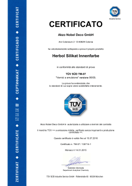
Dauner Antriebstechnik GmbH
Magnum
PARAMETRI DI FUNZIONAMENTO POMPE
General data pumps
Pressione max.
Max pressure
Cilindrata
Pompa tipo
Displacement
p1
Pump type
cm 3 /giro
cu in/rev
p2
p3
Min speed
min - 1
17,20
1.05
HDP 30•22 *
21,89
1.33
HDP 30•27
26,58
1.62
HDP 30•34
34,39
2.09
270
3900
290
4200
310
4500
HDP 30•43
43,77
2.67
260
3770
280
4060
300
4350
HDP 30•51
51,59
3.14
230
3300
260
3770
HDP 30•61
60,97
3.72
200
2900
HDP 30•73
73,47
4.48
HDP 30•82
81,29
4.96
HDP 35•50
50,77
3.09
HDP 35•63
63,46
3.87
HDP 35•71
71,92
4.38
HDP 35•80
80,39
4.90
HDP 35•90
280
4060
300
4350
320
4640
3000
400
280
4060
2500
300
230
3300
250
3625
2000
190
2750
210
3040
230
3300
1700
170
2400
190
2750
210
3040
1500
270
3900
280
4060
310
4500
250
3000
250
3625
280
4060
300
4350
90,96
5.55
230
3300
260
3770
280
4060
HDP 35•100
99,43
6.06
210
3040
240
3480
260
3770
HDP 35•112
112,12
6.84
190
2750
220
3190
240
3480
HDP 35•125
124,81
7.61
170
2400
200
2900
220
3190
I valori in tabella sono riferiti a pompe unidirezionali.
The values in the table refer to unidirectional pumps.
Pressione max. continua
Velocità min
Max speed
bar
psi
HDP 30•17 *
p1= Max. continuous pressure
Velocità max
400
2700
2500
250
* Disponibili solo nelle versioni 2 e 4
* Available only on 2 and 4 version
Pressione max. intermittente
p2= Max. intermittent pressure
Pressione max. di punta
p3= Max. peak pressure
Le pressioni max delle pompe reversibili sono inferiori del 15% rispetto a quelle riportate in tabella,
per condizioni d’impiego non citate in tabella consultare il nostro servizio tecnico commerciale.
Reversible pumps max pressures are 15% lower than those shown in table. For different working
conditions please consult our sales department.
036-010
Dauner Antriebstechnik GmbH – Industriestraße 3 – 96120 Bischberg – Trosdorf
Tel.: 09503/50008-0 – Fax: 09503/50008-49 – Email: [email protected] – www.dauner-antriebstechnik.de
Die Inhalte unserer Seiten wurden mit größter Sorgfalt erstellt. Für die Richtigkeit, Vollständigkeit und Aktualität der Inhalte können wir jedoch keine Gewähr übernehmen.
Dauner Antriebstechnik GmbH
Magnum
DETERMINAZIONE DI UNA POMPA
Design calculations for pumps
Q
[l/min]
Portata
Delivery
M
[Nm]
Coppia
Torque
P
[kW]
Potenza
Power
V
3
[cm /giro] - [cm /rev]
Cilindrata
Displacement
n
[min-1]
Velocità
Speed
[bar]
Pressione
Pressure
Δp
3
ηv= ηv (V,Δp, n)
(≈ 0,98)
Rendimento volumetrico
Volumetric efficiency
ηm= ηm (V,Δp, n)
(≈ 0,90)
Rendimento meccanico
Mechanical efficiency
ηt
(≈ 0,88)
Rendimento totale
Overall efficiency
Q= V•ηv•n•10-3
M=
Δp• V
[l/min]
[Nm]
62,8•ηm
P=
Δp•V•n
612•1000•ηt
[kW]
Nota : Nelle seguenti pagine troverete dei diagrammi che vi permetteranno di di fare dei calcoli approssimativi.
Note : Diagrams providing approximate selection data will be found on subsequent pages.
036-010
Dauner Antriebstechnik GmbH – Industriestraße 3 – 96120 Bischberg – Trosdorf
Tel.: 09503/50008-0 – Fax: 09503/50008-49 – Email: [email protected] – www.dauner-antriebstechnik.de
Die Inhalte unserer Seiten wurden mit größter Sorgfalt erstellt. Für die Richtigkeit, Vollständigkeit und Aktualität der Inhalte können wir jedoch keine Gewähr übernehmen.
Dauner Antriebstechnik GmbH
Magnum
CURVE CARATTERISTICHE POMPE HDP 30
HDP 30 gear pumps performance curves
HDP 30
Le curve sono state ottenute alla temperatura di
50°C, utilizzando olio con viscosità 36 mm2/s a
40°C e alle pressioni sotto riportate.
Each curve has been obtained at 50°C, using oil
with viscosity 36 mm2/s at 40°C and at these
pressures.
(1) 20-280 bar
(2) 20-270 bar
(3) 20-260 bar
(4) 20-230 bar
(5) 20-200 bar
(6) 20-190 bar
(7) 20-170 bar
HDP 30•17
HDP 30•22
036-010
Dauner Antriebstechnik GmbH – Industriestraße 3 – 96120 Bischberg – Trosdorf
Tel.: 09503/50008-0 – Fax: 09503/50008-49 – Email: [email protected] – www.dauner-antriebstechnik.de
Die Inhalte unserer Seiten wurden mit größter Sorgfalt erstellt. Für die Richtigkeit, Vollständigkeit und Aktualität der Inhalte können wir jedoch keine Gewähr übernehmen.
Dauner Antriebstechnik GmbH
Magnum
HDP 30•27
HDP 30•34
HDP 30•43
HDP 30•51
036-010
Dauner Antriebstechnik GmbH – Industriestraße 3 – 96120 Bischberg – Trosdorf
Tel.: 09503/50008-0 – Fax: 09503/50008-49 – Email: [email protected] – www.dauner-antriebstechnik.de
Die Inhalte unserer Seiten wurden mit größter Sorgfalt erstellt. Für die Richtigkeit, Vollständigkeit und Aktualität der Inhalte können wir jedoch keine Gewähr übernehmen.
Dauner Antriebstechnik GmbH
Magnum
HDP 30•61
HDP 30•73
HDP 30•82
036-010
Dauner Antriebstechnik GmbH – Industriestraße 3 – 96120 Bischberg – Trosdorf
Tel.: 09503/50008-0 – Fax: 09503/50008-49 – Email: [email protected] – www.dauner-antriebstechnik.de
Die Inhalte unserer Seiten wurden mit größter Sorgfalt erstellt. Für die Richtigkeit, Vollständigkeit und Aktualität der Inhalte können wir jedoch keine Gewähr übernehmen.
Dauner Antriebstechnik GmbH
Magnum
CURVE CARATTERISTICHE POMPE HDP 35
HDP 35 gear pumps performance curves
HDP 35
Le curve sono state ottenute alla temperatura di
50°C, utilizzando olio con viscosità 36 mm2/s a
40°C e alle pressioni sotto riportate.
Each curve has been obtained at 50°C, using oil
with viscosity 36 mm2/s at 40°C and at these
pressures.
(1) 20-270 bar
(2) 20-250 bar
(3) 20-230 bar
(4) 20-210 bar
(5) 20-190 bar
(6) 20-170 bar
HDP 35•50
HDP 35•63
036-010
Dauner Antriebstechnik GmbH – Industriestraße 3 – 96120 Bischberg – Trosdorf
Tel.: 09503/50008-0 – Fax: 09503/50008-49 – Email: [email protected] – www.dauner-antriebstechnik.de
Die Inhalte unserer Seiten wurden mit größter Sorgfalt erstellt. Für die Richtigkeit, Vollständigkeit und Aktualität der Inhalte können wir jedoch keine Gewähr übernehmen.
Dauner Antriebstechnik GmbH
Magnum
HDP 35•71
HDP 35•90
HDP 35•80
HDP 35•100
036-010
Dauner Antriebstechnik GmbH – Industriestraße 3 – 96120 Bischberg – Trosdorf
Tel.: 09503/50008-0 – Fax: 09503/50008-49 – Email: [email protected] – www.dauner-antriebstechnik.de
Die Inhalte unserer Seiten wurden mit größter Sorgfalt erstellt. Für die Richtigkeit, Vollständigkeit und Aktualität der Inhalte können wir jedoch keine Gewähr übernehmen.
Dauner Antriebstechnik GmbH
Magnum
HDP 35•112
HDP 35•125
036-010
Dauner Antriebstechnik GmbH – Industriestraße 3 – 96120 Bischberg – Trosdorf
Tel.: 09503/50008-0 – Fax: 09503/50008-49 – Email: [email protected] – www.dauner-antriebstechnik.de
Die Inhalte unserer Seiten wurden mit größter Sorgfalt erstellt. Für die Richtigkeit, Vollständigkeit und Aktualität der Inhalte können wir jedoch keine Gewähr übernehmen.
Dauner Antriebstechnik GmbH
Magnum
PARAMETRI DI FUNZIONAMENTO MOTORI
General data motors
Pressione max.
Max pressure
Cilindrata
Motore tipo
Displacement
p1
p2
p3
Velocità max
Velocità min
Max speed
Min speed
Motor type
cm 3 /giro
cu in/rev
bar
psi
min - 1
HDM 30•17 *
17,20
1.05
HDM 30•22 *
21,89
1.33
HDM 30•27
26,58
1.62
HDM 30•34
34,39
2.09
270
3900
290
4200
310
4500
HDM 30•43
43,77
2.67
260
3770
280
4060
300
4350
HDM 30•51
51,59
3.14
230
3300
260
3770
HDM 30•61
60,97
3.72
200
2900
HDM 30•73
73,47
4.48
HDM 30•82
81,29
4.96
HDM 35•50
50,77
3.09
HDM 35•63
63,46
3.87
HDM 35•71
71,92
4.38
HDM 35•80
80,39
4.90
HDM 35•90
280
4060
300
4350
320
4640
3000
400
280
4060
2500
300
230
3300
250
3625
2000
190
2750
210
3040
230
3300
1700
170
2400
190
2750
210
3040
1500
270
3900
280
4060
310
4500
3000
250
3625
280
4060
300
4350
90,96
5.55
230
3300
260
3770
280
4060
HDM 35•100
99,43
6.06
210
3040
240
3480
260
3770
HDM 35•112
112,12
6.84
190
2750
220
3190
240
3480
HDM 35•125
124,81
7.61
170
2400
200
2900
220
3190
I valori in tabella sono riferiti a motori unidirezionali.
The values in the table refer to unidirectional motors.
Pressione max. continua
p1= Max. continuous pressure
250
400
2700
2500
250
* Disponibili solo nelle versioni 2 e 4
* Available only on 2 and 4 version
Pressione max. intermittente
p2= Max. intermittent pressure
Pressione max. di punta
p3= Max. peak pressure
Le pressioni max dei motori reversibili sono inferiori del 15% rispetto a quelle riportate in tabella,
per condizioni d’impiego non citate in tabella consultare il nostro servizio tecnico commerciale.
Reversible motors max pressures are 15% lower than those shown in table. For different working
conditions please consult our sales department.
036-010
Dauner Antriebstechnik GmbH – Industriestraße 3 – 96120 Bischberg – Trosdorf
Tel.: 09503/50008-0 – Fax: 09503/50008-49 – Email: [email protected] – www.dauner-antriebstechnik.de
Die Inhalte unserer Seiten wurden mit größter Sorgfalt erstellt. Für die Richtigkeit, Vollständigkeit und Aktualität der Inhalte können wir jedoch keine Gewähr übernehmen.
Dauner Antriebstechnik GmbH
Magnum
DETERMINAZIONE DI UN MOTORE
Design calculations for motors
Q
[l/min]
Portata
Delivery
M
[Nm]
Coppia
Torque
P
[kW]
Potenza
Power
V
3
[cm /giro] - [cm /rev]
Cilindrata
Displacement
n
[min-1]
Velocità
Speed
[bar]
Pressione
Pressure
Δp
3
ηv= ηv (V,Δp, n)
(≈ 0,97)
Rendimento volumetrico
Volumetric efficiency
ηm= ηm (V,Δp, n)
(≈ 0,88)
Rendimento meccanico
Mechanical efficiency
ηt
(≈ 0,85)
Rendimento totale
Overall efficiency
Q=
M=
V•n•10-3
ηv
Δp•V•ηm
[l/min]
[Nm]
62,8
P=
Δp•V•n•η
[kW]
612•1000
Nota : Nelle seguenti pagine troverete dei diagrammi che vi permetteranno di di fare dei calcoli approssimativi.
Note : Diagrams providing approximate selection data will be found on subsequent pages.
036-010
Dauner Antriebstechnik GmbH – Industriestraße 3 – 96120 Bischberg – Trosdorf
Tel.: 09503/50008-0 – Fax: 09503/50008-49 – Email: [email protected] – www.dauner-antriebstechnik.de
Die Inhalte unserer Seiten wurden mit größter Sorgfalt erstellt. Für die Richtigkeit, Vollständigkeit und Aktualität der Inhalte können wir jedoch keine Gewähr übernehmen.
Dauner Antriebstechnik GmbH
Magnum
CURVE CARATTERISTICHE MOTORI HDM 30
HDM 30 gear motors performance curves
HDM 30
Le curve sono state ottenute alla temperatura di
50°C, utilizzando olio con viscosità 36 mm2/s a
40°C e alle pressioni sotto riportate.
Each curve has been obtained at 50°C, using oil
with viscosity 36 mm2/s at 40°C and at these
pressures.
(1) 20-280 bar
(2) 20-270 bar
(3) 20-260 bar
(4) 20-230 bar
(5) 20-200 bar
(6) 20-190 bar
(7) 20-170 bar
HDM 30•17
HDM 30•22
036-010
Dauner Antriebstechnik GmbH – Industriestraße 3 – 96120 Bischberg – Trosdorf
Tel.: 09503/50008-0 – Fax: 09503/50008-49 – Email: [email protected] – www.dauner-antriebstechnik.de
Die Inhalte unserer Seiten wurden mit größter Sorgfalt erstellt. Für die Richtigkeit, Vollständigkeit und Aktualität der Inhalte können wir jedoch keine Gewähr übernehmen.
Dauner Antriebstechnik GmbH
Magnum
HDM 30•27
HDM 30•34
HDM 30•43
HDM 30•51
036-010
Dauner Antriebstechnik GmbH – Industriestraße 3 – 96120 Bischberg – Trosdorf
Tel.: 09503/50008-0 – Fax: 09503/50008-49 – Email: [email protected] – www.dauner-antriebstechnik.de
Die Inhalte unserer Seiten wurden mit größter Sorgfalt erstellt. Für die Richtigkeit, Vollständigkeit und Aktualität der Inhalte können wir jedoch keine Gewähr übernehmen.
Dauner Antriebstechnik GmbH
Magnum
HDM 30•61
HDM 30•73
HDM 30•82
036-010
Dauner Antriebstechnik GmbH – Industriestraße 3 – 96120 Bischberg – Trosdorf
Tel.: 09503/50008-0 – Fax: 09503/50008-49 – Email: [email protected] – www.dauner-antriebstechnik.de
Die Inhalte unserer Seiten wurden mit größter Sorgfalt erstellt. Für die Richtigkeit, Vollständigkeit und Aktualität der Inhalte können wir jedoch keine Gewähr übernehmen.
Dauner Antriebstechnik GmbH
Magnum
CURVE CARATTERISTICHE MOTORI HDM 35
HDM 35 gear motors performance curves
HDM 35
Le curve sono state ottenute alla temperatura di
50°C, utilizzando olio con viscosità 36 mm2/s a
40°C e alle pressioni sotto riportate.
Each curve has been obtained at 50°C, using oil
with viscosity 36 mm2/s at 40°C and at these
pressures.
(1) 20-270 bar
(2) 20-250 bar
(3) 20-230 bar
(4) 20-210 bar
(5) 20-190 bar
(6) 20-170 bar
HDM 35•50
HDM 35•63
036-010
Dauner Antriebstechnik GmbH – Industriestraße 3 – 96120 Bischberg – Trosdorf
Tel.: 09503/50008-0 – Fax: 09503/50008-49 – Email: [email protected] – www.dauner-antriebstechnik.de
Die Inhalte unserer Seiten wurden mit größter Sorgfalt erstellt. Für die Richtigkeit, Vollständigkeit und Aktualität der Inhalte können wir jedoch keine Gewähr übernehmen.
Dauner Antriebstechnik GmbH
Magnum
HDM 35•71
HDM 35•80
HDM 35•90
HDM 35•100
036-010
Dauner Antriebstechnik GmbH – Industriestraße 3 – 96120 Bischberg – Trosdorf
Tel.: 09503/50008-0 – Fax: 09503/50008-49 – Email: [email protected] – www.dauner-antriebstechnik.de
Die Inhalte unserer Seiten wurden mit größter Sorgfalt erstellt. Für die Richtigkeit, Vollständigkeit und Aktualität der Inhalte können wir jedoch keine Gewähr übernehmen.
Dauner Antriebstechnik GmbH
Magnum
HDM 35•112
HDM 35•125
036-010
Dauner Antriebstechnik GmbH – Industriestraße 3 – 96120 Bischberg – Trosdorf
Tel.: 09503/50008-0 – Fax: 09503/50008-49 – Email: [email protected] – www.dauner-antriebstechnik.de
Die Inhalte unserer Seiten wurden mit größter Sorgfalt erstellt. Für die Richtigkeit, Vollständigkeit und Aktualität der Inhalte können wir jedoch keine Gewähr übernehmen.
Dauner Antriebstechnik GmbH
Magnum
DIMENSIONI UNITA’ SINGOLE CON BOCCHE LATERALI
Single unit dimensions side ports
280 Nm
Pompa tipo
Pump type
Massa
A
B
C
D
E
mm
mm
mm
mm
mm
HD. 30•17
184,5
138
15,50
HD. 30•22
187,5
141
15,80
HD. 30•27
190,5
144
16,20
HD. 30•34
195,5
149
Motore tipo
Motor type
Mass
kg
16,80
23,45
150
155
HD. 30•43
201,5
155
17,60
HD. 30•51
206,5
160
18,20
HD. 30•61
212,5
166
19,00
HD. 30•73
220,5
174
19,70
HD. 30•82
225,5
179
20,30
HD. 35•50
229,5
177
23,70
HD. 35•63
235,5
183
24,70
HD. 35•71
239,5
187
25,40
HD. 35•80
243,5
191
HD. 35•90
248,5
196
26,80
HD. 35•100
252,5
200
27,50
HD. 35•112
258,5
206
28,50
HD. 35•125
264,5
212
29,50
27,35
172
175
26,00
036-010
Dauner Antriebstechnik GmbH – Industriestraße 3 – 96120 Bischberg – Trosdorf
Tel.: 09503/50008-0 – Fax: 09503/50008-49 – Email: [email protected] – www.dauner-antriebstechnik.de
Die Inhalte unserer Seiten wurden mit größter Sorgfalt erstellt. Für die Richtigkeit, Vollständigkeit und Aktualität der Inhalte können wir jedoch keine Gewähr übernehmen.
Dauner Antriebstechnik GmbH
Magnum
DIMENSIONI UNITA’ SINGOLE CON BOCCHE POSTERIORI
Single unit dimensions rear ports
280 Nm
Pompa tipo
Pump type
Massa
A
B
C
D
E
mm
mm
mm
mm
mm
HD. 30•17
184,5
173
15,50
HD. 30•22
187,5
176
15,80
HD. 30•27
190,5
179
16,20
HD. 30•34
195,5
184
Motore tipo
Motor type
Mass
kg
16,80
23,45
150
75
HD. 30•43
201,5
190
17,60
HD. 30•51
206,5
195
18,20
HD. 30•61
212,5
201
19,00
HD. 30•73
220,5
209
19,70
HD. 30•82
225,5
214
20,30
HD. 35•50
229,5
218
23,70
HD. 35• 63
235,5
224
24,70
HD. 35•71
239,5
228
25,40
HD. 35•80
243,5
232
HD. 35•90
248,5
237
26,80
HD. 35•100
252,5
241
27,50
HD. 35•112
258,5
247
28,50
HD. 35•125
264,5
253
29,50
27,35
172
89
26,00
036-010
Dauner Antriebstechnik GmbH – Industriestraße 3 – 96120 Bischberg – Trosdorf
Tel.: 09503/50008-0 – Fax: 09503/50008-49 – Email: [email protected] – www.dauner-antriebstechnik.de
Die Inhalte unserer Seiten wurden mit größter Sorgfalt erstellt. Für die Richtigkeit, Vollständigkeit und Aktualität der Inhalte können wir jedoch keine Gewähr übernehmen.
Dauner Antriebstechnik GmbH
Magnum
POMPE MULTIPLE
Multiple pumps
Le pompe MAGNUM possono essere combinate in unità multiple tenendo presente che l’assorbimento
di potenza di ogni unità deve essere maggiore o uguale di quello della successiva. Le caratteristiche
e le prestazioni di ogni pompa sono le stesse delle singole corrispondenti, tuttavia bisogna tenere conto
dei seguenti limiti:
Le pressioni sono limitate dalla coppia trasmissibile dall’albero di trascinamento della prima pompa
e dall’albero che collega le singole pompe tra loro e possono essere determinate caso per caso con
la formula riportata sotto.
La velocità max di rotazione è determinata dalla pompa che ha velocità minore.
E’ offerta la possibilità di pompe doppie con una sola bocca di aspirazione in comune ai due elementi.
Nell’ accoppiamento MAGNUM + KAPPA e MAGNUM + serie C è standard la soluzione a stadi
separati.
MAGNUM pumps can be coupled together in combination. Where imput power requirement of each
element varies, that with the greater requirement must be at the drive shaft end, and progressively
smaller to the rear.
Features and performances are the same as for the corresponding single pumps, but pressures
must be limited by the transmissible torque of the drive shaft and connecting shafts. To have appropriate
data, use the formulae below.
The maximum rotational speed is that of the lowest rated speed of the single units incorporated.
We offer the possibility to have pumps with only one inlet port for the two elements. Combination
MAGNUM + KAPPA series and MAGNUM + C series are standard the elements sealed internally one
from another.
M
[Nm]
V
3
Δp
Coppia
Torque
[cm /giro] - [cm /rev]
Cilindrata
Displacement
[bar]
Pressione
Pressure
Rendimento meccanico
Mechanical efficiency
ηm= ηm (V,Δp, n)
3
(≈ 0,90)
M=
Δp • V
62,8• η m
[Nm]
N.B.: La coppia assorbita dall’albero della prima pompa è data dalla somma delle coppie dei singoli
stadi. Il valore così ottenuto non deve superare quello massimo ammesso per il tipo di albero prescelto
per la prima pompa.
N.B.: The torque absorbed from the shaft of the first pump results from the sum of the torques due to
all single stages. The achieved value must not exceed the maximum torque limit given for the shaft of
the first pump.
036-010
Dauner Antriebstechnik GmbH – Industriestraße 3 – 96120 Bischberg – Trosdorf
Tel.: 09503/50008-0 – Fax: 09503/50008-49 – Email: [email protected] – www.dauner-antriebstechnik.de
Die Inhalte unserer Seiten wurden mit größter Sorgfalt erstellt. Für die Richtigkeit, Vollständigkeit und Aktualität der Inhalte können wir jedoch keine Gewähr übernehmen.
Dauner Antriebstechnik GmbH
Magnum
COPPIA ASSORBITA
Absorbed torque
HDP 35
KP 20 - Gr.2 Sr.C
HDP 30
1
3
2
SCELTA DELL’ALBERO DI TRASCINAMENTO
Prendiamo in esame una pompa doppia HDP35•80+
HDP30•27. Supponendo di dover lavorare con la prima
pompa ad una pressione di 200 bar e con la seconda ad
una pressione di 150 bar, dal grafico 1 troviamo che la
coppia assorbita dalla HDP35•80 è di 284 Nm e dal grafico
2 che la HDP30•27 assorbe una coppia di 70 Nm (valore
accettabile perché non supera la coppia massima trasmissibile dal manicotto di collegamento fissata a 170 Nm, vedi
pag. 1.40 - 1.41). La coppia che dovrà quindi trasmettere
l’albero della prima pompa sarà di 284+70= 354 Nm,
valore che non deve superare quello limite ammesso
dall’albero.
DRIVE SHAFT SELECTION
Let us consider a double pump HDP35•80 + HDP30•27.
If we suppose that we have to work with the first pump at
a pressure of 200 bar and the second pump at a pressure
of 150 bar, the graph 1 shows that the torque absorbed by
HDP35•80 is 284 Nm and the graph 2 shows that the
torque absorbed by HDP30•27 is 70 Nm (acceptable value
because it does not exceed the maximum connecting shaft
torque that is 170 Nm, see page 1.40 - 1.41). The torque
to be transmitted by the first drive shaft will thus be
036-010
Dauner Antriebstechnik GmbH – Industriestraße 3 – 96120 Bischberg – Trosdorf
Tel.: 09503/50008-0 – Fax: 09503/50008-49 – Email: [email protected] – www.dauner-antriebstechnik.de
Die Inhalte unserer Seiten wurden mit größter Sorgfalt erstellt. Für die Richtigkeit, Vollständigkeit und Aktualität der Inhalte können wir jedoch keine Gewähr übernehmen.
Dauner Antriebstechnik GmbH
Magnum
DIMENSIONI POMPE MULTIPLE
Multiple pumps dimensions
280 Nm
Pompa tipo
Pump type
A
B
C
D
E
F
G
mm
mm
mm
mm
mm
mm
mm
HDP 30+HDP 30
115+H
70+H
70+H
54,5
24,5
23,45
80
HDP 35+HDP 35
139+H
82+H
82+H
60,5
26,5
27,35
98
Pompa tipo
Pump type
H
H
I
L
M
N
O
mm
mm
mm
mm
mm
mm
70
75,5
150
133,5
155
82
91,5
175
162,4
175
Vedi sotto
See below
Vedi sotto
See below
Pompa tipo
Pump type
mm
H
mm
HDP 30•17
23
HDP 35•50
38
HDP 30•22
26
HDP 35•63
44
HDP 30•27
29
HDP 35•71
48
HDP 30•34
34
HDP 35•80
52
HDP 30•43
40
HDP 35•90
57
HDP 30•51
45
HDP 35•100
61
HDP 30•61
51
HDP 35•112
67
HDP 30•73
59
HDP 35•125
73
HDP 30•82
64
036-010
Dauner Antriebstechnik GmbH – Industriestraße 3 – 96120 Bischberg – Trosdorf
Tel.: 09503/50008-0 – Fax: 09503/50008-49 – Email: [email protected] – www.dauner-antriebstechnik.de
Die Inhalte unserer Seiten wurden mit größter Sorgfalt erstellt. Für die Richtigkeit, Vollständigkeit und Aktualität der Inhalte können wir jedoch keine Gewähr übernehmen.
Dauner Antriebstechnik GmbH
Magnum
DIMENSIONI POMPE MULTIPLE HDP 35 + HDP 30
HDP 35 + HDP 30 multiple pumps dimensions
280 Nm
Pompa tipo
Pump type
Pompa tipo
Pump type
A
mm
mm
HDP 35+HDP 30
139+C
76+D
C
B
Pompa tipo
Pump type
mm
D
mm
HDP 35•50
38
HDP 30•17
23
HDP 35•63
44
HDP 30•22
26
HDP 35•71
48
HDP 30•27
29
HDP 35•80
52
HDP 30•34
34
HDP 35•90
57
HDP 30•43
40
HDP 35•100
61
HDP 30•51
45
HDP 35•112
67
HDP 30•61
51
HDP 35•125
73
HDP 30•73
59
HDP 30•82
64
036-010
Dauner Antriebstechnik GmbH – Industriestraße 3 – 96120 Bischberg – Trosdorf
Tel.: 09503/50008-0 – Fax: 09503/50008-49 – Email: [email protected] – www.dauner-antriebstechnik.de
Die Inhalte unserer Seiten wurden mit größter Sorgfalt erstellt. Für die Richtigkeit, Vollständigkeit und Aktualität der Inhalte können wir jedoch keine Gewähr übernehmen.
Dauner Antriebstechnik GmbH
Magnum
DIMENSIONI POMPE MULTIPLE HDP 30 + KP 20
HDP 30 + KP 20 multiple pumps dimensions
25 Nm
280 Nm
Le caratteristiche di funzionamento delle pompe serie KAPPA sono illustrate sul catalogo tecnico K.
The general data of KAPPA series pumps are explained on K technical catalogue.
Pompa tipo
Pump type
A
Pompa tipo
Pump type
mm
B
C
mm
mm
HDP 30•17
138
KP 20•4
HDP 30•22
141
KP 20•6,3
HDP 30•27
144
KP 20•8
HDP 30•34
149
KP 20•11,2
HDP 30•43
155
KP 20•14
146
HDP 30•51
160
KP 20•16
151,5
HDP 30•61
166
KP 20•20
158
HDP 30•73
174
KP 20•25
151
HDP 30•82
179
KP 20•31,5
161
139
141,5
27,5
144
147,5
33
48
036-010
Dauner Antriebstechnik GmbH – Industriestraße 3 – 96120 Bischberg – Trosdorf
Tel.: 09503/50008-0 – Fax: 09503/50008-49 – Email: [email protected] – www.dauner-antriebstechnik.de
Die Inhalte unserer Seiten wurden mit größter Sorgfalt erstellt. Für die Richtigkeit, Vollständigkeit und Aktualität der Inhalte können wir jedoch keine Gewähr übernehmen.
Dauner Antriebstechnik GmbH
Magnum
DIMENSIONI POMPE MULTIPLE HDP + Gr. 2 SERIE C
HDP + C series Gr.2 multiple pumps dimensions
50 Nm
280 Nm
Le caratteristiche di funzionamento delle pompe serie C sono illustrate sul catalogo tecnico CP.
The general data of C series pumps are explaned on CP technical catalogue.
Pompa tipo
Pump type
A
B
C
D
mm
mm
mm
Ve d i s o t t o
See below
HDP 30 + Gr. 2
115+E
35
Ve d i s o t t o
See below
HDP 35 + Gr. 2
139+E
41
Ve d i s o t t o
See below
Pompa tipo
Pump type
C
D
mm
mm
CPL 4,8
E
F
G
H
mm
mm
mm
mm
mm
Ve d i s o t t o
See below
Ve d i s o t t o
See below
23,45
7,55
155
Ve d i s o t t o
See below
27,35
11,55
175
Pompa tipo
Pump type
E
Pompa tipo
Pump type
mm
E
mm
HDP 30•17
23
HDP 35•50
38
HDP 30•22
26
HDP 35•63
44
CPL 9
HDP 30•27
29
HDP 35•71
48
CPL 13
HDP 30•34
34
HDP 35•80
52
HDP 30•43
40
HDP 35•90
57
HDP 30•51
45
HDP 35•100
61
HDP 30•61
51
HDP 35•112
67
HDP 30•73
59
HDP 35•125
73
HDP 30•82
64
CPL 6,2
CPL 16
47,5
56
57
65,5
CPL 20
CPL 26
63,5
67
036-010
Dauner Antriebstechnik GmbH – Industriestraße 3 – 96120 Bischberg – Trosdorf
Tel.: 09503/50008-0 – Fax: 09503/50008-49 – Email: [email protected] – www.dauner-antriebstechnik.de
Die Inhalte unserer Seiten wurden mit größter Sorgfalt erstellt. Für die Richtigkeit, Vollständigkeit und Aktualität der Inhalte können wir jedoch keine Gewähr übernehmen.
Dauner Antriebstechnik GmbH
Magnum
VERSIONI
Versions
0
1
Versione per impieghi senza carichi radiali e assiali sull’albero.
Versione per impieghi con limitati carichi
radiali e senza carichi
assiali sull’albero.
Version for applications without radial
and axial load on the
drive shaft.
Version for applications with low radial
load and without axial
load on the drive
shaft.
2
Versione speciale
con albero indipendente per impieghi
senza carichi radiali e
assiali sull’albero.
Special version with
independent shaft for
applications without
radial and axial load
on the drive shaft.
4
Versione per impieghi con carichi radiali
e assiali sull’albero.
Version for applications with radial and
axial load on the drive
shaft.
036-010
Dauner Antriebstechnik GmbH – Industriestraße 3 – 96120 Bischberg – Trosdorf
Tel.: 09503/50008-0 – Fax: 09503/50008-49 – Email: [email protected] – www.dauner-antriebstechnik.de
Die Inhalte unserer Seiten wurden mit größter Sorgfalt erstellt. Für die Richtigkeit, Vollständigkeit und Aktualität der Inhalte können wir jedoch keine Gewähr übernehmen.
Dauner Antriebstechnik GmbH
Magnum
ESTREMITA’ ALBERI DI TRASCINAMENTO
End drive shafts
32
04
SAE B cilindrico
SAE B scanalato
13 denti - 16/32 DP
radice piana centraggio
sui fianchi.
ISO 22 - 4
SAE B keyed
SAE B splined
13 teeth - 16/32 DP
flat root side fit.
SAE J 498 b
MAX 300 Nm
*
MAX 200 Nm
05
33
SAE BB scanalato
15 denti - 16/32 DP
radice piana centraggio
sui fianchi.
ISO 25 - 4
SAE BB splined
15 teeth - 16/32 DP
flat root side fit.
SAE J 498 b
SAE BB cilindrico
SAE BB keyed
MAX 450 Nm
MAX 280 Nm
*
06
*
34
SAE C scanalato
14 denti - 12/24 DP
radice piana centraggio
sui fianchi.
ISO 32 - 4
SAE C splined
14 teeth - 12/24 DP
flat root side fit.
SAE J 498 b
*
SAE C cilindrico
SAE C keyed
*
*
*
*
HD. 30 MAX 170 Nm
HD. 30 MAX 170 Nm
HD. 35 MAX 900 Nm
HD. 35 MAX 600 Nm
* Per qualsiasi estremità d’albero in caso di versione "2" e "4" HD.30 Mmax= 170 Nm - HD.35 Mmax= 350 Nm.
* For "2" and "4" version whichever end shaft HD.30 Mmax= 170 Nm - HD.35 Mmax= 350 Nm.
036-010
Dauner Antriebstechnik GmbH – Industriestraße 3 – 96120 Bischberg – Trosdorf
Tel.: 09503/50008-0 – Fax: 09503/50008-49 – Email: [email protected] – www.dauner-antriebstechnik.de
Die Inhalte unserer Seiten wurden mit größter Sorgfalt erstellt. Für die Richtigkeit, Vollständigkeit und Aktualität der Inhalte können wir jedoch keine Gewähr übernehmen.
Dauner Antriebstechnik GmbH
Magnum
FLANGE DI MONTAGGIO E TABELLA DI COMPATIBILITA’
Mounting flanges and table of compatibility
SAE A 2 FORI
SAE A 2 Holes
S1
A L B E R I D I T R A S C I N A M E N T O V E D I PA G . 1 . 3 1
Drive shafts see page 1.31
GRUPPO
Group
V E R S I O N I V E D I PA G . 1 . 3 0
Ve r s i o n s s e e p a g e 1 . 3 0
04
32
05
33
0
■
■
•
•
1
•
•
•
•
2
■
■
•
•
HD.30
06
34
•
•
■ COMBINAZIONE STANDARD - Standard combination
• COMBINAZIONE DISPONIBILE - Available combination
SAE B 2-4 FORI
SAE B 2-4 Holes
S3
A L B E R I D I T R A S C I N A M E N T O V E D I PA G . 1 . 3 1
Drive shafts see page 1.31
GRUPPO
Group
HD.30
V E R S I O N I V E D I PA G . 1 . 3 0
Ve r s i o n s s e e p a g e 1 . 3 0
04
32
05
33
0
■
■
•
•
1
■
■
•
•
2
■
■
•
4
■
■
•
06
34
•
•
•
•
•
•
■ COMBINAZIONE STANDARD - Standard combination
• COMBINAZIONE DISPONIBILE - Available combination
036-010
Dauner Antriebstechnik GmbH – Industriestraße 3 – 96120 Bischberg – Trosdorf
Tel.: 09503/50008-0 – Fax: 09503/50008-49 – Email: [email protected] – www.dauner-antriebstechnik.de
Die Inhalte unserer Seiten wurden mit größter Sorgfalt erstellt. Für die Richtigkeit, Vollständigkeit und Aktualität der Inhalte können wir jedoch keine Gewähr übernehmen.
Dauner Antriebstechnik GmbH
Magnum
FLANGE DI MONTAGGIO E TABELLA DI COMPATIBILITA’
Mounting flanges and table of compatibility
SAE C 2-4 FORI
SAE C 2-4 Holes
S8
GRUPPO
Group
A
B
HD.30
80
167,9
HD.35
98
182,8
A L B E R I D I T R A S C I N A M E N T O V E D I PA G . 1 . 3 1
Drive shafts see page 1.31
GRUPPO
Group
V E R S I O N I V E D I PA G . 1 . 3 0
Ve r s i o n s s e e p a g e 1 . 3 0
04
32
05
33
06
34
2
•
•
•
•
■
■
4
•
•
•
•
■
■
0
■
■
1
■
■
HD.30
HD.35
2
•
•
•
•
■
■
4
•
•
•
•
■
■
■ COMBINAZIONE STANDARD - Standard combination
• COMBINAZIONE DISPONIBILE - Available combination
SAE B 4 FORI
SAE B 4 Holes
S4
A L B E R I D I T R A S C I N A M E N T O V E D I PA G . 1 . 3 1
Drive shafts see page 1.31
GRUPPO
Group
HD.35
V E R S I O N I V E D I PA G . 1 . 3 0
Ve r s i o n s s e e p a g e 1 . 3 0
04
32
05
33
06
34
0
•
•
1
•
•
2
■
■
•
•
•
•
4
■
■
•
•
•
•
■ COMBINAZIONE STANDARD - Standard combination
• COMBINAZIONE DISPONIBILE - Available combination
036-010
Dauner Antriebstechnik GmbH – Industriestraße 3 – 96120 Bischberg – Trosdorf
Tel.: 09503/50008-0 – Fax: 09503/50008-49 – Email: [email protected] – www.dauner-antriebstechnik.de
Die Inhalte unserer Seiten wurden mit größter Sorgfalt erstellt. Für die Richtigkeit, Vollständigkeit und Aktualität der Inhalte können wir jedoch keine Gewähr übernehmen.
Dauner Antriebstechnik GmbH
Magnum
FLANGE DI MONTAGGIO E TABELLA DI COMPATIBILITA’
Mounting flanges and table of compatibility
SAE B 2 FORI
SAE B 2 Holes
S5
A L B E R I D I T R A S C I N A M E N T O V E D I PA G . 1 . 3 1
Drive shafts see page 1.31
GRUPPO
Group
HD.35
V E R S I O N I V E D I PA G . 1 . 3 0
Ve r s i o n s s e e p a g e 1 . 3 0
04
32
05
33
06
34
0
•
•
1
•
•
2
■
■
•
•
•
•
4
■
■
•
•
•
•
■ COMBINAZIONE STANDARD - Standard combination
• COMBINAZIONE DISPONIBILE - Available combination
036-010
Dauner Antriebstechnik GmbH – Industriestraße 3 – 96120 Bischberg – Trosdorf
Tel.: 09503/50008-0 – Fax: 09503/50008-49 – Email: [email protected] – www.dauner-antriebstechnik.de
Die Inhalte unserer Seiten wurden mit größter Sorgfalt erstellt. Für die Richtigkeit, Vollständigkeit und Aktualität der Inhalte können wir jedoch keine Gewähr übernehmen.
Dauner Antriebstechnik GmbH
Magnum
BOCCHE
Ports
L
H
K
P
BOCCHE LATERALI
SIDE PORTS
BOCCHE POSTERIORI
REAR PORTS
BOCCHE
SSS
SSM
BSPP
ODT
BSPP
ODT
PORTS
POMPA TIPO
PUMP TYPE
IN
OUT
IN
OUT
IN
OUT
IN
OUT
IN
OUT
IN
OUT
MOTORE TIPO
MOTOR TYPE
OUT
IN
OUT
IN
OUT
IN
OUT
IN
OUT
IN
OUT
IN
SC
SB
MC
MB
GF
GE
OF
OD
GE
GE
OD
OD
SD
SC
MD
MC
GG
GF
OG
OF
GF *
GE
GH
GG
OG
OF
OF
OD
GG *
GF
HD. 30•17
HD. 30•22
HD. 30•27
HD. 30•34
HD. 30•43
HD. 30•51
HD. 30•61
HD. 30•73
SE
SD
ME
MD
SE
SD
ME
MD
HD. 30•82
HD. 35•50
HD. 35•63
HD. 35•71
HD. 35•80
HD. 35•90
HD. 35•100
SF
SE
MF
ME
GL
GH
OH
OG
HD. 35•112
HD. 35•125
* NON DISPONIBILE PER POMPE E MOTORI REVERSIBILI CON DRENAGGIO ESTERNO.
* Not available for reversible pumps and motors with external drain.
036-010
Dauner Antriebstechnik GmbH – Industriestraße 3 – 96120 Bischberg – Trosdorf
Tel.: 09503/50008-0 – Fax: 09503/50008-49 – Email: [email protected] – www.dauner-antriebstechnik.de
Die Inhalte unserer Seiten wurden mit größter Sorgfalt erstellt. Für die Richtigkeit, Vollständigkeit und Aktualität der Inhalte können wir jedoch keine Gewähr übernehmen.
Dauner Antriebstechnik GmbH
Magnum
BOCCHE PER DRENAGGIO ESTERNO HD.30 - HD.35
HD.30 - HD.35 external drain ports
Le pompe e i motori reversibili tipo (R) hanno il drenaggio esterno.
The reversible pumps and motors (R) type have the external drain.
BOCCHE PER POMPE MULTIPLE
Ports for multiple pumps
L
L’aspirazione e la mandata mantengono le stesse dimensioni delle bocche
laterali delle pompe singole (vedi pag. 1.36).
Inlet and outlet ports are the same as side ports of single pumps (see page 1.36).
BOCCHE
SSS
SSM
BSPP
ODT
IN
IN
IN
IN
HDP 30
SE
ME
GG
OG
HDP 35
SF
MF
GL
OH
PORTS
L
POMPA TIPO
PUMP TYPE
La mandata mantiene le stesse dimensioni delle bocche di mandata laterali delle
pompe singole (vedi pag. 1.36).
Outlet ports are the same as outlet side ports of single pumps (see page 1.36).
Per altre combinazioni consultare il nostro servizio tecnico commerciale.
For other combinations please consult our sales departement.
036-010
Dauner Antriebstechnik GmbH – Industriestraße 3 – 96120 Bischberg – Trosdorf
Tel.: 09503/50008-0 – Fax: 09503/50008-49 – Email: [email protected] – www.dauner-antriebstechnik.de
Die Inhalte unserer Seiten wurden mit größter Sorgfalt erstellt. Für die Richtigkeit, Vollständigkeit und Aktualität der Inhalte können wir jedoch keine Gewähr übernehmen.
Dauner Antriebstechnik GmbH
Magnum
DIMENSIONI BOCCHE
Port sizes
BOCCHE FLANGIATE SAE CON FILETTATURA UNC (SSS)
SAE FLANGED PORTS UNC THREADED (SSS)
CODICE
DIMENSIONE
NOMINALE
NOMINAL SIZE
A
B
C
D
CODE
mm
mm
mm
mm
SA
1/2"
12,5
38,1
17,5
24
5/16"-18 UNC-2B
SB
3/4"
19
47,6
22,2
22
3/8"-16 UNC-2B
SC
1"
25,4
52,4
26,2
SD
1"1/4
30,5
58,7
30,2
28,5
7/16"-14 UNC-2B
SE
1"1/2
39,3
69,8
35,7
27
1/2"-13 UNC-2B
SF
2"
51
77,8
42,9
E
BOCCHE FLANGIATE SAE CON FILETTATURA METRICA (SSM)
SAE FLANGED PORTS METRIC THREAD (SSM)
CODICE
A
B
C
D
CODE
DIMENSIONE
NOMINALE
NOMINAL SIZE
mm
mm
mm
mm
MA
1/2"
12,5
38,1
17,5
MB
3/4"
19
47,6
22,2
MC
1"
25,4
52,4
26,2
MD
1"1/4
30,5
58,7
30,2
ME
1"1/2
39,3
69,8
35,7
MF
2"
51
77,8
42,9
E
M 8
22
M 10
27
M12
BOCCHE FILETTATE (BSPP)
BRITISH STANDARD PIPE PARALLEL (BSPP)
CODICE
A
CODE
DIMENSIONE
NOMINALE
NOMINAL SIZE
GD
1/2"
G1/2
GE
3/4"
G3/4
20
24,5
GF
1"
G1
22
30,5
GG
1"1/4
G11/4
24
39,3
GH
1"1/2
G11/2
26
45
GL
2"
G 2
32
56
B
C
mm
mm
18
19
036-010
Dauner Antriebstechnik GmbH – Industriestraße 3 – 96120 Bischberg – Trosdorf
Tel.: 09503/50008-0 – Fax: 09503/50008-49 – Email: [email protected] – www.dauner-antriebstechnik.de
Die Inhalte unserer Seiten wurden mit größter Sorgfalt erstellt. Für die Richtigkeit, Vollständigkeit und Aktualität der Inhalte können wir jedoch keine Gewähr übernehmen.
Dauner Antriebstechnik GmbH
Magnum
DIMENSIONI BOCCHE
Port sizes
BOCCHE FILETTATE SAE (ODT)
SAE STRAIGHT THREAD (ODT)
CODICE
DIMENSIONE
NOMINALE
NOMINAL SIZE
A
CODE
OB
1/2"
3/4"-16 UNF-2B
OD
3/4"
1"-1/16-12 UN-2B
OF
1"
1"-5/16-12 UN-2B
OG
1"1/4
1"-5/8-12 UN-2B
60
OH
1"1/2
1"-7/8-12 UN-2B
70
B
C
D
E
mm
mm
mm
mm
15
32
2,5
42
20
50
0,5
3,3
VERSIONI COPERCHIO POSTERIORE
Rear cover versions
Tutte le pompe multiple con più di due sezioni sono fornite con staffa di fissaggio 8 o 9.
All multiple pumps with more than two sections are available with bracket 8 or 9 version.
Aspirazione comune
Common inlet port
Aspirazione separata
Separated inlet port
Senza staffa di fissaggio
Without bracket
Con staffa di fissaggio
With bracket
0
9
1
8
036-010
Dauner Antriebstechnik GmbH – Industriestraße 3 – 96120 Bischberg – Trosdorf
Tel.: 09503/50008-0 – Fax: 09503/50008-49 – Email: [email protected] – www.dauner-antriebstechnik.de
Die Inhalte unserer Seiten wurden mit größter Sorgfalt erstellt. Für die Richtigkeit, Vollständigkeit und Aktualität der Inhalte können wir jedoch keine Gewähr übernehmen.
Dauner Antriebstechnik GmbH
Magnum
FLANGE INTERMEDIE E ALBERI DI COLLEGAMENTO
Shafts and intermediate flanges for connection
HD. 35 + HD. 35
Flange d’ accoppiamento
Connecting flanges
350 Nm
F0
F1
60
Albero di
collegamento
Connecting shaft
61
Albero di
collegamento
Connecting shaft
HD. 35 + HD. 30
Flangia d’ accoppiamento
Connecting flange
170 Nm
G0
G1
Flangia d’ accoppiamento
Connecting flange
HD. 35 + Gr. 2 Sr. C
I0
63
Albero di collegamento
stadi separati
Separate stages
connecting shaft
62
Albero di
collegamento
Connecting shaft
110 Nm
Flangia d’ accoppiamento
Connecting flange
I1
036-010
Dauner Antriebstechnik GmbH – Industriestraße 3 – 96120 Bischberg – Trosdorf
Tel.: 09503/50008-0 – Fax: 09503/50008-49 – Email: [email protected] – www.dauner-antriebstechnik.de
Die Inhalte unserer Seiten wurden mit größter Sorgfalt erstellt. Für die Richtigkeit, Vollständigkeit und Aktualität der Inhalte können wir jedoch keine Gewähr übernehmen.
Dauner Antriebstechnik GmbH
Magnum
FLANGE INTERMEDIE E ALBERI DI COLLEGAMENTO
Shafts and intermediate flanges for connection
HDP 30+ HDP 30
Flange d’ accoppiamento
Connecting flanges
170 Nm
M0
M1
65
Flangia d’ accoppiamento
Connecting flange
Albero di collegamento
Connecting shaft
HDP 30+ KP 20
N0
68
110 Nm
Albero di collegamento
stadi separati
Separate stages
connecting shaft
Flangia d’ accoppiamento
Connecting flange
70 Nm
N1
73
Flangia d’ accoppiamento
Connecting flange
P0
Albero di collegamento
Connecting shaft
HDP 30 + Gr. 2 Sr. C
110 Nm
67
Albero di collegamento
stadi separati
Separate stages
connecting shaft
Flangia d’ accoppiamento
Connecting flange
P1
66
Albero di collegamento
Connecting shaft
036-010
Dauner Antriebstechnik GmbH – Industriestraße 3 – 96120 Bischberg – Trosdorf
Tel.: 09503/50008-0 – Fax: 09503/50008-49 – Email: [email protected] – www.dauner-antriebstechnik.de
Die Inhalte unserer Seiten wurden mit größter Sorgfalt erstellt. Für die Richtigkeit, Vollständigkeit und Aktualität der Inhalte können wir jedoch keine Gewähr übernehmen.
Dauner Antriebstechnik GmbH
Magnum
INSTALLAZIONE
Pompa
Assicurarsi, nel caso di pompe unidirezionali, che il senso di rotazione sia coerente con quello dell’albero
dal quale deriva il moto. Assicurarsi che la flangia di montaggio realizzi un buon allineamento fra l’albero
di trasmissione e l’albero della pompa, il collegamento non deve indurre carichi radiali o assiali sull’albero
della pompa nel caso di utilizzo delle versioni 0, 1, 2.
Motore
Assicurarsi, nel caso di motori unidirezionali, che il senso di rotazione sia coerente con i collegamenti del
circuito. Assicurarsi che la flangia di montaggio realizzi un buon allineamento fra l’albero dell’utilizzo e
l’albero del motore, il collegamento non deve indurre carichi radiali o assiali sull’albero del motore nel caso
di utilizzo delle versioni 0, 1, 2.
SERBATOIO
La capacità del serbatoio deve essere in accordo con le condizioni d’esercizio dell’ impianto (~ 3 volte l’olio
in circolazione), per evitare surriscaldamenti del fluido, se necessario installare uno scambiatore. Nel
serbatoio le condotte di ritorno e aspirazione devono essere distanziate (interponendo una paratia verticale)
per evitare che l’olio di ritorno venga subito riaspirato.
TUBAZIONI
Le tubazioni devono avere un diametro nominale non inferiore a quello delle bocche della pompa o del
motore ed essere perfettamente a tenuta. Per limitare le perdite di carico, realizzare il percorso delle
tubazioni più corto possibile riducendo al minimo il numero delle resistenze idrauliche (gomiti, strozzamenti,
saracinesche). E’ consigliabile interporre sulle tubazioni un tratto di tubo flessibile, per ridurre la trasmissione di vibrazioni. Tutte le tubazioni di ritorno devono finire al di sotto del livello minimo dell’olio, per evitare
formazioni di schiuma. Prima di collegare le tubazioni togliere eventuali tappi di chiusura e assicurarsi che
siano perfettamente pulite.
FILTRAZIONE
Noi consigliamo una filtrazione su tutta la portata dell’impianto, i filtri devono essere montati rispettando le
indicazioni riportate nelle prime pagine del catalogo, sull’aspirazione delle pompe sono consentiti solo se
grossolani.
FLUIDO IDRAULICO
Impiegare fluidi idraulici conformi alle tabelle riportate nelle prime pagine del catalogo. Evitare miscele di
oli diversi che potrebbero dare origine a una decomposizione dell’olio e ridurre il suo potere lubrificante.
MESSA IN FUNZIONE
Assicurarsi che tutti i collegamenti del circuito siano esatti e che l’impianto sia in condizioni di assoluta
pulizia. Immettere l’olio nel serbatoio servendosi sempre di un filtro. Sfiatare il circuito per favorire il
riempimento dell’impianto. Tarare le valvole limitatrici di pressione al valore più basso possibile. Avviare
l’impianto per qualche istante alla minima velocità quindi sfiatare ulteriormente il circuito e verificare il livello
dell’olio nel serbatoio. Se la differenza di temperatura tra la pompa o il motore e quella del fluido supera i
10 °C, avviare e arrestare l’impianto per brevi periodi in modo da realizzare un riscaldamento progressivo.
Aumentare infine gradatamente la pressione e la velocità di rotazione fino a raggiungere i valori di esercizio
previsti che devono mantenersi entro i limiti dati a catalogo.
CONTROLLI PERIODICI - MANUTENZIONE
Mantenere la superficie esterna pulita soprattutto nella zona della tenuta dell’albero di trascinamento, la
polvere abrasiva può infatti accelerare l’usura della tenuta stessa e causare perdite. Sostituire il filtro con
regolarità per mantenere il fluido pulito. Il livello dell’olio deve essere controllato e sostituito periodicamente
a seconda delle condizioni di lavoro dell’impianto.
036-010
Dauner Antriebstechnik GmbH – Industriestraße 3 – 96120 Bischberg – Trosdorf
Tel.: 09503/50008-0 – Fax: 09503/50008-49 – Email: [email protected] – www.dauner-antriebstechnik.de
Die Inhalte unserer Seiten wurden mit größter Sorgfalt erstellt. Für die Richtigkeit, Vollständigkeit und Aktualität der Inhalte können wir jedoch keine Gewähr übernehmen.
Dauner Antriebstechnik GmbH
Magnum
INSTALLATION
Pump
The direction of rotation of single-rotation pumps must be the same as that of the drive shaft. Check that
the coupling flange correctly aligns the transmission shaft and the pump shaft, the connection do not
generate an axial or radial load on the pump shaft in the applications of 0, 1, 2 versions.
Motor
The direction of rotation of single-acting motors must match circuit connections. Check that the coupling
flange correctly aligns the user shaft and the motor shaft, the connection do not generate an axial or
radial load on the motor shaft in the applications of 0, 1, 2 versions.
TANK
Tank capacity must be sufficient for the system’s operating conditions (3 times the amount of oil in
circulation) to avoid overheating of the fluid. A heat exchanger should be installed if necessary. The
intake and return lines in the tank must be spaced apart (by inserting a vertical divider) to prevent the
return-line oil from being taken up again immediately.
LINES
The lines must have a major diameter which is at least as large as the diameter of motor or pump ports,
and must be perfectly sealed. To reduce loss of power, the lines should be as short as possible, reducing
the sources of hydraulic resistance (elbow, throttling, gate valves, etc.) to a minimum. A length of flexible
tubing is recommended to reduce the transmission of vibrations. All return lines must end below the
minimum oil level, to prevent foaming. Before connecting the lines, remove any plugs and make sure
that the lines are perfectly clean.
FILTERS
We recommend filtering the entire system flow. Filters should be fitted as indicated in the first pages of
the catalogue. Only coarse filters are recommended for pump intake.
HYDRAULIC FLUID
Use hydraulic fluid conforming to the table as specified in the first pages of the catalogue. Avoid using
mixtures of different oils which could result in decomposition and reduction of the oil’s lubricating power.
STARTING UP
Check that all circuit connections are tight and that the entire system is completely clean. Insert the oil
in the tank, using a filter. Bleed the circuit to assist in filling. Set the pressure relief valves to the lowest
possible setting. Turn on the system for a few moments at minimum speed, then bleed the circuit again
and check the level of oil in the tank. If the difference between pump or motor temperature and fluid
temperature exceeds 10 °C, rapidly switch the system on and off to heat it up gradually. Then gradually
increase the pressure and speed of rotation until the pre-set operating levels as specified in the catalogue
are attained.
PERIODICAL CHECKS - MAINTENANCE
Keep the outside surface clean especially in the area of the drive shaft seal. In fact, abrasive powder
can accelerate wear on the seal and cause leakage. Replace filters regularly to keep the fluid clean. The
oil level must be checked and oil replaced periodically depending on the system’s operating conditions.
036-010
Dauner Antriebstechnik GmbH – Industriestraße 3 – 96120 Bischberg – Trosdorf
Tel.: 09503/50008-0 – Fax: 09503/50008-49 – Email: [email protected] – www.dauner-antriebstechnik.de
Die Inhalte unserer Seiten wurden mit größter Sorgfalt erstellt. Für die Richtigkeit, Vollständigkeit und Aktualität der Inhalte können wir jedoch keine Gewähr übernehmen.
Dauner Antriebstechnik GmbH
Magnum
Come ordinare una unità singola
How to order single unit
Prima di ordinare consultare la tabella di compatibilità albero flangia e versione alle pagine 1.32 - 1.33 - 1.34
Before ordering consult shaft flange and version table compatibility at pages 1.32 - 1.33 - 1.34
HDP 30•34
S
0
– 04
S3 –
L
MC / MB –
N
Guarnizione N - V - V-Bz
vedi pag. 1.3
Seal N - V - V-Bz
see page 1.4
Pompa tipo - Motore tipo
vedi pag. 1.6 - 1.14
Pump type - Motor type
see page 1.6 - 1.14
Rotazione: S=sinistra - D=destra
R= reversibile - B=reversibile drenaggio interno
Rotation: S=left - D=right
R=reversible - B=reversible internal drain
Versione: 0 - 1 - 2 - 4 vedi pag. 1.30
Version: 0 - 1 - 2 - 4 see page 1.30
Codice albero di trascinamento 04-05-06-32-33-34 vedi pag. 1.31
Drive shaft code 04-05-06-32-33-34 see page 1.31
Codice bocca di uscita (OUT)
vedi pag. 1.36 - 1.37 - 1.38 - 1.39
Outlet port code (OUT)
see pages 1.36 - 1.37 - 1.38 - 1.39
Codice bocca di ingresso (IN)
vedi pag. 1.36 - 1.37 - 1.38 - 1.39
Inlet port code (IN)
see pages 1.36 - 1.37 - 1.38 - 1.39
Codice posizione bocche L - P - H - K vedi pag. 1.36
Port position code L - P - H - K see page 1.36
Codice flangia di montaggio S1-S3-S4-S5-S8
vedi pag. 1.32 - 1.34
Mounting flange code S1-S3-S4-S5-S8
see pages 1.32 - 1.34
036-010
Dauner Antriebstechnik GmbH – Industriestraße 3 – 96120 Bischberg – Trosdorf
Tel.: 09503/50008-0 – Fax: 09503/50008-49 – Email: [email protected] – www.dauner-antriebstechnik.de
Die Inhalte unserer Seiten wurden mit größter Sorgfalt erstellt. Für die Richtigkeit, Vollständigkeit und Aktualität der Inhalte können wir jedoch keine Gewähr übernehmen.
Dauner Antriebstechnik GmbH
Magnum
Come ordinare una unità multipla
How to order multiple units
Prima di ordinare consultare la tabella di compatibilità albero flangia e versione alle pagine 1.32 - 1.33 - 1.34
Before ordering consult shaft flange and version table compatibility at pages 1.32 - 1.33 - 1.34
HDP 35•80
S
0
- 06
S8 -
L
SE / SD - 61
G0 -
N
A
HDP
30•43
S
-
L
SD / SC - 65
M0 -
N
I
HDP
30•34
S
-
L
SC / SB -
M 9 -
N
P
A=anteriore
A=front
I=intermedia
I=intermediate
P=posteriore
P=rear
Pompa tipo
vedi pag. 1.6
Pump type
see page 1.6
Rotazione:
S=sinistra - D=destra
Rotation:
S=left - D=right
Guarnizione N - V - V-Bz
vedi pag. 1.3
Seal N - V - V-Bz
see page 1.4
Versione: 0 - 1 - 2 - 4 vedi pag. 1.30
Version: 0 - 1 - 2 - 4 see page 1.30
Coperchio posteriore vedi pag. 1.39
Rear cover see page 1.39
Codice flangia sezione precedente
Connecting flange code of the previous section
Codice albero di trascinamento
04-05-06-32-33-34 vedi pag. 1.31
Drive shaft code 04-05-06-32-33-34 see page 1.31
Codice flangia di montaggio S1-S3-S4- S5-S8
vedi pag. 1.32 - 1.34
Mounting flange code S1-S3-S4-S5-S8 see pages 1.32 - 1.34
Flangia d’ accoppiamento
vedi pag. 1.40 - 1.41
Connecting flange see pages 1.40 -1.41
Albero di collegamento vedi pag. 1.40 - 1.41
Connecting shaft see pages 1.40 - 1.41
Codice posizione bocche L - P - H - K vedi pag. 1.36
Port position code L - P - H - K see page 1.36
Codice bocca di uscita (OUT)
vedi pag. 1.36 - 1.37 - 1.38 - 1.39
Outlet port code (OUT)
see pages 1.36 - 1.37 - 1.38 - 1.39
Codice bocca di ingresso (IN) vedi pag. 1.36 - 1.37 - 1.38 - 1.39
Inlet port code (IN) see pages 1.36 - 1.37 - 1.38 - 1.39
Codice da tralasciare solo nell’ordine di unità assemblate.
Omit code only if ordering complete multiple assembly.
Come ordinare una unità multipla MAGNUM + KP 20 o serie C
How to order multiple units MAGNUM + KP 20 or C series
68
Sezione anteriore vedi codifica
unità multiple (vedi sopra)
Front section see how to order
multiple unit (see above)
N0 / KP 20•4
D
N
Guarnizione
Seal
N=buna - V=viton
Albero di collegamento vedi pag. 1.40 - 1.41
Connecting shaft see page 1.40 - 1.41
Rotazione: S=sinistra - D=destra
Rotation: S=left - D=right
Flangia d’ accoppiamento vedi pag. 1.40 - 1.41
Connecting flange see page 1.40-1.41
Pompa tipo vedi pag. 1.28 - 1.29
Pump type see pages 1.28 - 1.29
Per maggiori informazioni su pompe serie KAPPA e serie C, consultare i rispettivi cataloghi tecnici.
For more information on KAPPA and C series, consult the respective technical catalogues.
036-010
Dauner Antriebstechnik GmbH – Industriestraße 3 – 96120 Bischberg – Trosdorf
Tel.: 09503/50008-0 – Fax: 09503/50008-49 – Email: [email protected] – www.dauner-antriebstechnik.de
Die Inhalte unserer Seiten wurden mit größter Sorgfalt erstellt. Für die Richtigkeit, Vollständigkeit und Aktualität der Inhalte können wir jedoch keine Gewähr übernehmen.
Dauner Antriebstechnik GmbH
Magnum
ESEMPI DI ORDINAZIONE
Order example
Esempio d’ordine di una sezione anteriore
Order example for front section
HDP 35•80 S0-06 S8-L SE/SD-61 G0-N A
Esempio d’ordine di una sezione intermedia
Order example for intermediate section
HDP 30•43 S-L SD/SC-65 M0-N I
Esempio di ordinazione di una sezione posteriore
Order example for rear section
HDP 30•34 S-L SC/SB-M9-N P
Esempio di ordinazione di una unità tripla assemblata
Order example for assembled triple unit
HDP 35•80 S0-06 S8-L SE/SD-61 G0+30•43 L SD/SC-65 M0+30•34 L SC/SB-M9-N
La nostra politica è orientata verso il miglioramento continuo dei prodotti pertanto le caratteristiche degli stessi possono cambiare senza preavviso.
Our policy is one of continuous improvement in product. Specification of items may, therefore, be changed without
notice.
036-010
Dauner Antriebstechnik GmbH – Industriestraße 3 – 96120 Bischberg – Trosdorf
Tel.: 09503/50008-0 – Fax: 09503/50008-49 – Email: [email protected] – www.dauner-antriebstechnik.de
Die Inhalte unserer Seiten wurden mit größter Sorgfalt erstellt. Für die Richtigkeit, Vollständigkeit und Aktualität der Inhalte können wir jedoch keine Gewähr übernehmen.
Scarica