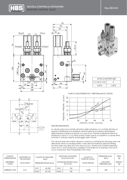
Gruppi di riduzione e misura gas
Gas pressure reducing and metering stations
Gruppi di riduzione e misura gas
Gas pressure reducing and metering stations
I gruppi di riduzione e misura
gas metano sono destinati alla
decompressione e misura del
gas naturale per alimentare le
reti di distribuzione cittadine
o direttamente le utenze
industriali e/o artigianali.
CPL CONCORDIA ha progettato
i gruppi di riduzione in modo
da eseguire le operazioni di
conduzione e manutenzione
solamente dal fronte; questo
consente l’installazione del
gruppo a parete o in prossimità
di una recinzione, riducendo le
difficoltà di posizionamento.
A richiesta sono disponibili
gruppi di riduzione a basso
livello di emissione sonora; i
gruppi possono essere forniti
completi di armadio metallico
di contenimento o di altri
manufatti prefabbricati.
Gruppo di riduzione
linea semplice
Gas pressure reducing stations
(GPRS) are used in natural gas
industry to reduce gas pressure
and measure the flow of natural
gas supplied to city networks
and commercial and industrial
customers.
CPL CONCORDIA gas pressure
reducing stations are engineered
to allow the maintenance
from front side only, the main
advantage is the installation
flexibility because the GPRS
should be installed directly onto
a wall or a fence.
Low noise GPRS and GPRS
accessories
like
aluminium
and stainless steel cabinet,
carbon steel and stainless steel
shelters and concrete shelters are
available on request.
POSIZIONE
DESCRIZIONE
ITEM
DESCRIPTION
Gruppo di riduzione gas in linea
semplice costruito in accordo alle
normative vigenti.
L’impianto è costituito da una linea
completa di filtro a cartuccia con
indicatore di intasamento, regolatore
di pressione e dispositivi di sicurezza
(valvola di blocco incorporata e/o
secondo regolatore con funzione di
monitor), valvole di intercettazione e
relativi accessori.
La linea di bypass è dotata di una valvola
di intercettazione e di una valvola di
regolazione a flusso avviato.
1
Giunto dielettrico / Insulating joint
2
Rubinetto portamanometro /
Pressure gauge valve
3
Valvola / Valve
4
Filtro a cartuccia / Cartridge filter
4,1
Indicatore di intasamento /
Clogging indicator
5
Manometro / Pressure gauge
6
6,1
Gas pressure reducing
station for distribution
networks
Single stream gas pressure reducing
station designed according to applicable
local regulations.
The GPRS consists of a reducing stream
complete of cartridge filter with
differential pressure indicator, main
regulator (active) and safety devices
(built-in slam-shut and/or stand-by
monitor regulator), on-off isolating
valves and accessories (pressure
indicators, testing valves, etc).
In order to allow an easy maintenance
a manual by-pass stream is provided,
the stream includes an on-off isolating
valve and a needle valve.
Schema di flusso e schema
P&ID and general arran
3
Regolatore di pressione monitor /
Pressure regolator monitor
4,1
5
PDI
PI
4
MAIN LINE / LINEA PRINCIPALE
6
2
2
7
2 2
8
6,1
Valvola di blocco / Slam shut valve
7
Regolatore di pressione /
Pressure regolator
8
Valvola / Valve
9
Valvola a sfera / Ball valve full bore
10
Valvola di sfioro / Relief valve
11
Giunto dielettrico / Insulating joint
12
Valvola a sfera / Ball valve
13
Valvola a spillo / Needle valve
14
Armadio / Cabinet
10
BY-PASS
12
13
2
PSV
9
2
1
14
11
Tipo regolatore
action type reg.

diretta/direct
GRC M1D 50
GRC M1D 100
GRC M2D 200
GRC M2D 300
GRC M2D 400
GRC M2D 500
GRC M2N 500
GRC M2N 800
GRC M2N 900
GRC M2N 1100
GRC M2N 1300
GRC M2N 1600
GRC M2N 2000
Pilotato/Piloted
GRC M2R 1100
GRC M2R 1500
GRC M2R 1800
GRC M2R 2100
Trivalente/Three
GRC M2T 1000
GRC M2T 1500
GRC M2T 1800
GRC M2T 2100
diretta/direct
GRC M1D 50
GRC M1D 100
GRC M2D 200
GRC M2D 300
GRC M2D 500
GRC M2D 700
GRC M2N 900
GRC M2N 1100
GRC M2N 1300
GRC M2N 1800
GRC M2N 2200
Pilotato/Piloted
GRC M2R 1500
GRC M2R 2000
INLET
min max
bar


OUTLET
bar

0,5
5
≤ 40 mbar


1
5
≤ 0,5
PORTATA
Flowrate
m3/h
A1
A
SICUREZZE
Safety
Tipo
BY-PASS
DN
ARMADIO
Cabinet
mm
50
100
200
300
400
500
500
800
900
1100
1300
1600
2000

1100
1500
1800
2100

1000
1500
1800
2100
25
25
40
50
65
65
65
80
100
100
100
125
125

100
100
125
125

100
100
125
125
GP1
GP1
G1
G1
G1,5
G1,5
G1,5
G2
G2
G2,5
G2,5
G2,5
G3

G2,5
G2,5
G2,5
G3

G2,5
G2,5
G2,5
G3
25
25x40
32
40
40
50
40
50
50
65
65
80
80

50
65
65
80

50
65
65
80
40
50
65
80
80
100
100
125
125
125
150
150
200

125
150
200
200

125
150
200
200
Bl
Bl
Bl+Mo
Bl+Mo
Bl+Mo
Bl+Mo
Bl+Mo
Bl+Mo
Bl+Mo
Bl+Mo
Bl+Mo
Bl+Mo
Bl+Mo

Bl+Mo
Bl+Mo
Bl+Mo
Bl+Mo

Bl+Mo
Bl+Mo
Bl+Mo
Bl+Mo
25
25
25
25
25
25
50
50
50
50
50

50
50
50
50

50
50
50
50
700x500x1100 H
700x500x1100 H
1400x800x1700 H
1600x800x1700 H
1600x800x1700 H
1800x900x1700 H
1800x900x1700 H
2000x1000x2000 H
2000x1000x2000 H
2400x1200x2000 H
2400x1200x2000 H
2400x1200x2000 H
2400x1200x2000 H

2000x1000x2000 H
2400x1200x2000 H
2400x1200x2000 H
2400x1200x2000 H

1600x800x1700 H
1600x800x1700 H
1800x900x1700 H
1800x900x1700 H
50
100
200
300
500
700
900
1100
1300
1800
2200

1500
2000
25
25
32
40
50
65
65
80
80
100
100

100
100
GP1
GP1
G0,5
G1
G1
G1,5
G1,5
G2
G2
G2,5
G2,5

G2
G2,5
25
25x40
32
32
40
50
50
50
65
65
80

50
65
40
50
50
65
80
100
100
100
125
150
150

125
150
Bl
Bl
Mo
Mo
Mo
Mo
Mo
Mo
Mo
Mo
Mo

Mo
Mo
25
25
25
25
25
25
25
50
50

50
50
700x500x1100 H
700x500x1100 H
1200x700x1700 H
1400x800x1700 H
1600x800x1700 H
1800x900x1700 H
1800x900x1700 H
1800x900x1700 H
2000x1000x2000 H
2400x1200x2000 H
2400x1200x2000 H

1400x800x1700 H
1600x800x1700 H
Bl = Valvola di blocco / Slam shut valve
Mo = Monitor / 2nd regulator
ema costruttivo
arrangement
GRUPPI CIVILI MAGLIATI
REDUCING STATION SINGLE LINE
INLET
FILTRO
RIDUTTORE
OUTLET

Filter
Regulator
mm
Tipo
mm
mm
INT
A-A1
mm

310
350
1000
1150
1175
1250
1300
1390
1400
1650
1700
1725
1750

1400
1600
1750
1750

950
1000
1050
1100

310
350
850
1000
1150
1250
1300
1250
1450
1550
1600

850
1000
Gruppi di riduzione e misura gas
Gas pressure reducing and metering stations
Gruppo di riduzione
doppia linea
Schema di flusso e schema costruttivo
P&ID and general arrangement
4,1
5
PDI
PI
MAIN LINE / LINEA PRINCIPALE
2
6
7
2
3
4
8
5
PDI
PI
11 2 12
2
9
10
2 2
6,1
10,1
Gruppo di riduzione gas in doppia linea costruito in accordo alle normative vigenti.
L’impianto è costituito da due linee
identiche, di cui una di servizio e una
di soccorso, complete di filtro a cartuccia con indicatore di intasamento,
regolatore di pressione e dispositivi di
sicurezza (valvola di blocco incorporata e/o secondo regolatore con funzio-
15
2 2
PSV
13
11,1
14
2
2
1
17
A1
16
A
POSIZIONE
DESCRIZIONE
ITEM
DESCRIPTION
1
Giunto dielettrico / Insulating joint
2
Rubinetto portamanometro /
Pressure gauge valve
3
Valvola / Valve
4
Filtro a cartuccia / Cartridge filter
4,1
Indicatore di intasamento /
Clogging indicator
5
Manometro / Pressure gauge
6
Regolatore di pressione monitor /
Pressure regolator monitor
6,1
Valvola di blocco / Slam shut valve
7
Regolatore di pressione /
Pressure regolator
8
Valvola / Valve
9
Valvola / Valve
10
Filtro a cartuccia / Cartridge filter
10,1
Indicatore di intasamento /
Clogging indicator
Regolatore di pressione monitor /
Pressure regolator monitor
11
11,1
Valvola di blocco / Slam shut valve
12
Regolatore di pressione /
Pressure regolator
13
Valvola / Valve
14
Valvola a sfera/ Ball valve
15
Valvola di sfioro / Relief valve
16
Giunto dielettrico / Insulating joint
17
Armadio / Cabinet
Gas pressure reducing
station for distribution
networks
Double stream gas pressure reducing
station designed according to applicable
local regulations.
The GPRS consists of two identical
reducing streams, one in operation,
the other in stand-by, each complete of
cartridge filter with differential pressure
indicator, main regulator (active) and
safety devices (built-in slam-shut and/
or stand-by monitor regulator), onoff isolating valves and accessories
(pressure indicators, testing valves,
etc).
ne di monitor), valvole di intercettazione e relativi accessori.
Tipo regolatore
Action type reg.

diretta/direct
GRC A1D 50
GRC A1D 100
GRC A2D 200
GRC A2D 300
GRC A2D 400
GRC A2D 500
GRC A2N 500
GRC A2N 800
GRC A2N 900
GRC A2N 1100
GRC A2N 1300
GRC A2N 1600
GRC A2N 2000
Pilotato/Piloted
GRC A2R 1100
GRC A2R 1500
GRC A2R 1800
GRC A2R 2100
Trivalente/Three
GRC A2T 1000
GRC A2T 1500
GRC A2T 1800
GRC A2T 2100
diretta/direct
GRC A1D 50
GRC A1D 100
GRC A2D 200
GRC A2D 300
GRC A2D 500
GRC A2D 700
GRC A2N 900
GRC A2N 1100
GRC A2N 1300
GRC A2N 1800
GRC A2N 2200
Pilotato/Piloted
GRC A2R 1500
GRC A2R 2000
INLET
min max
bar


OUTLET
bar

0,5
5
≤ 40 mbar


1
5
≤ 0,5
PORTATA
Flowrate
m3/h

50
100
200
300
400
500
500
800
900
1100
1300
1600
2000

1100
1500
1800
2100

1000
1500
1800
2100

50
100
200
300
500
700
900
1100
1300
1800
2200

1500
2000
Bl = Valvola di blocco / Slam shut valve
Mo = Monitor / 2nd regulator
GRUPPI CIVILI ANTENNA
REDUCING STATION DOUBLE LINE
INLET
FILTRO
RIDUTTORE

Filter
Regulator
mm
Tipo
mm


25
GP1
25
25
GP1
25x40
40
G1
32
50
G1
40
65
G1,5
40
65
G1,5
50
65
G1,5
40
80
G2
50
100
G2
50
100
G2,5
65
100
G2,5
65
125
G2,5
80
125
G3
80


100
G2,5
50
100
G2,5
65
125
G2,5
65
125
G3
80


100
G2,5
50
100
G2,5
65
125
G2,5
65
125
G3
80


25
GP1
25
25
GP1
25x40
32
G0,5
32
40
G1
32
50
G1
40
65
G1,5
50
65
G1,5
50
80
G2
50
80
G2
65
100
G2,5
65
100
G2,5
80


100
G2
50
100
G2,5
65
OUTLET
mm

40
50
65
80
80
100
100
125
125
125
150
150
200

125
150
200
200

125
150
200
200

40
50
50
65
80
100
100
100
125
150
150

125
150
SICUREZZE
Safety
Tipo

Bl
Bl
Bl+Mo
Bl+Mo
Bl+Mo
Bl+Mo
Bl+Mo
Bl+Mo
Bl+Mo
Bl+Mo
Bl+Mo
Bl+Mo
Bl+Mo

Bl+Mo
Bl+Mo
Bl+Mo
Bl+Mo

Bl+Mo
Bl+Mo
Bl+Mo
Bl+Mo

Bl
Bl
Mo
Mo
Mo
Mo
Mo
Mo
Mo
Mo
Mo

Mo
Mo
ARMADIO
Cabinet
mm

700x500x1100 H
1000x600x1700 H
1400x800x1700 H
1600x800x1700 H
1600x800x1700 H
1800x900x1700 H
2000x1000x2000 H
2000x1200x2000 H
2000x1200x2000 H
2400x1400x2400 H
2400x1400x2400 H
2400x1400x2400 H
3000x1500x2300 H

2000x1200x2000 H
2400x1200x2000 H
2400x1200x2000 H
3000x1500x2300 H

1800x1200x2000 H
1800x1200x2000 H
2000x1500x2300 H
2000x1500x2300 H

700x500x1100 H
700x500x1100 H
1200x700x1700 H
1400x700x1700 H
1600x800x1700 H
1800x900x1700 H
2000x1000x2000 H
2000x1200x2000 H
2000x1200x2000 H
2400x1400x2400 H
2400x1400x2400 H

1400x1000x2000 H
1800x1200x2000 H
INT
A-A1
mm

310
350
1000
1150
1175
1250
1300
1390
1400
1650
1700
1725
1750

1400
1600
1750
1750

900
1000
1050
1100

310
350
850
1000
1150
1250
1300
1250
1450
1550
1600

850
1000
Gruppi di riduzione e misura gas
Gas pressure reducing and metering stations
Gruppo riduzione
industriale
Schema di flusso e schema costruttivo
P&ID and general arrangement
4,1
5
PDI
PI
MAIN LINE / LINEA PRINCIPALE
6
2
3
7
5
PDI
PI
10
2
8
2 2
6,1
4
9,1
Gruppo di riduzione e misura gas costruito in accordo alle normative vigenti.
L’impianto prevede due linee di regolazione, con valvola di blocco incorporata, di cui una di soccorso all’altra, e sistema di misura completo di
contatore volumetrico e convertitore
di volumi PTZ.
Verniciatura secondo nostro standard o
2 2
11
10,1
9
RK
TT
17
12
FIT
18
13
13 15
2 DN
5 DN
2
1
PSV
13 13
14
2
19
A1
16
A
POSIZIONE
DESCRIZIONE
ITEM
DESCRIPTION
1
Giunto dielettrico / Insulating joint
2
Rubinetto portamanometro /
Pressure gauge valve
3
Valvola / Valve
4
Filtro a cartuccia / Cartridge filter
4,1
Indicatore di intasamento /
Clogging indicator
5
Manometro / Pressure gauge
6
Regolatore di pressione monitor /
Pressure regolator monitor
6,1
Valvola di blocco / Slam shut valve
7
Valvola / Valve
8
Valvola / Valve
9
Filtro a cartuccia / Cartridge filter
9,1
Indicatore di intasamento /
Clogging indicator
Regolatore di pressione monitor /
Pressure regolator monitor
10
10,1
Valvola di blocco / Slam shut valve
11
Valvola / Valve
12
Contatore / Flow meter
13
Valvola / Valve
13,1
Disco cieco-forato / Blind disc
14
Valvola a sfera / Ball valve
15
Valvola di sfioro / Relief valve
16
Giunto dielettrico / Insulating joint
17
Correttore di volumi / Flow computer
18
Tasca termometrica per PT100 /
Thermometer pocket for PT100
19
Armadio / Cabinet
Gas pressure reducing
station for industrial
and/or commercial use
Gas pressure reducing station for
industrial and/or networks.
Gas
pressure
reducing
station
designed according to applicable local
regulations.
The GPRS consists of two identical
reducing streams with built-in slamshut, one in operation, the other in
stand by, and a metering system with
turbine gas meter and PTZ volume
corrector. GPRS painting is available
according to our standard or to
customer specifications.
a specifica del cliente.
Tipo
Type

GRI M1D 100
GRI M1D 250
GRI M1D 400
GRI M1N 650
GRI M1N 1000
GRI M1N 2000
GRI A1D 100
GRI A1D 250
GRI A1D 400
GRI A1N 650
GRI A1N 1000
GRI A1N 2000
GRI M1D 100
GRI M1D 250
GRI M1D 400
GRI M1D 650
GRI M1N 1000
GRI M1N 2000
GRI A1D 100
GRI A1D 250
GRI A1D 400
GRI A1D 650
GRI A1N 1000
GRI A1N 2000
GRUPPI INDUSTRIALI
INDUSTRIAL REDUCING STATION
P. INLET
P.OUT n°LINEE PORTATA INLET
FILTRO RIDUTTORE DN IN
min max
n° line Flowrate
Filter  Regulator
Flow

3
bar
bar
M/A
m /h
mm
tipo
mm
mm
100
25
G0,5
25x40
50
250
50
G1
40
80
1 linea
400
65
G1,5
40
80
single
650
80
G2
50
100
line
1000
100
G2,5
65
150
2000
125
G3
80
200
≤ 40
0,5
5
mbar
100
25
G0,5
25x40
50
250
50
G1
40
80
2 linee
400
65
G1,5
40
80
double
650
80
G2
50
100
line
1000
100
G2,5
65
150
2000
125
G3
80
200
100
25
G0,5
25x40
50
250
40
G1
32
80
1 linea
400
50
G1
40
80
single
650
65
G1,5
50
100
line
1000
80
G2
50
150
2000
100
G2,5
80
150
1
5
≤ 0,5
100
25
G0,5
25x40
50
250
40
G1
32
80
2 linee
400
50
G1
40
80
double
650
65
G1,5
50
100
line
1000
80
G2
50
150
2000
100
G2,5
80
150
Bl = Valvola di blocco / Slam shut valve
MISURA  SICUREZZE BY-PASS
ARMADIO
Meeter
Safety
Cabinet
tipo
tipo
DN
mm
G65
1000x600x1700 H
G250
25
1200x700x1700 H
G250
25
1200x700x1700 H
Bl
G400
25
1400x800x1700 H
G650
50
1800x900x2000 H
G1600
50
3000x1500x2300 H
G65
50
1200x700x1700 H
G250
50
1400x800x1700 H
G250
50
1600x800x1700 H
Bl
G400
50
1800x1200x1700 H
G650
100
2400x1400x2400 H
G1600
150
3000x1500x2300 H
G65
1000x600x1700 H
G160
25
1200x700x1700 H
G250
25
1200x700x1700 H
Bl
G400
25
1400x800x1700 H
G650
25
1800x900x2000 H
G1000
50
1800x900x2000 H
G65
50
1200x700x1700 H
G160
50
1600x800x1700 H
G250
50
1600x800x1700 H
Bl
G400
50
1800x1200x1700 H
G650
100
2400x1200x2000 H
G1000
100
2400x1200x2000 H
CPL CONCORDIA Soc. Coop.
IMBR0408-P - ITA/ING
CPL CONCORDIA COMUNICAZIONE
via A. Grandi, 39 - 41033 Concordia s./S (MO) - ITALY - tel. +39.0535.616.111 - fax +39.0535.616.300
[email protected] - www.cpl.it
Scaricare