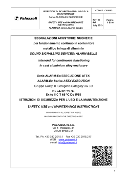
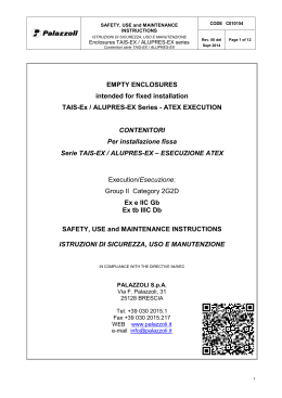
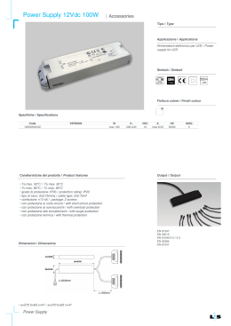
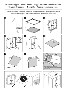
SAFETY, USE and MAINTENANCE INSTRUCTIONS
CODE C010153
ISTRUZIONI DI SICUREZZA, USO E MANUTENZIONE
Enclosures TAIS-EX with type of protection nR
Rev. 00
Contenitori TAIS-EX con modo di protezione nR
March 2013
Page
1 of 13
ENCLOSURES WITH TYPE OF PROTECTION nR
intended for fixed installation
TAIS-Ex Series - ATEX EXECUTION
CONTENITORI CON MODO DI PROTEZIONE nR
Per installazione fissa
Serie TAIS Ex – ESECUZIONE ATEX
Execution/Esecuzione:
Group II Category 3G 2D
Ex nR IIC Gc
Ex tb IIIC Db IP66
SAFETY, USE and MAINTENANCE INSTRUCTIONS
ISTRUZIONI DI SICUREZZA, USO E MANUTENZIONE
IN COMPLIANCE WITH THE DIRECTIVE 94/9/EC
PALAZZOLI S.p.A.
Via F. Palazzoli, 31
25128 BRESCIA
Tel. +39 030 2015.1 Fax +39 030 2015.217
WEB www.palazzoli.it
e-mail [email protected]
1
The Palazzoli enclosures of the TAIS-Ex in ATEX execution with type of
protection nR, comply to the provisions of the community Directive 94/9/EC
(ATEX). The equipments comply fully or for the individual applied parts to
the following harmonized standards:
Directive 94/9/CE
Direttiva 94/9/EC
Standard
Norma
Date
Data
EN 60079-0
2009
EN 60079-15
2010
EN 60079-31
2009
Directive 2006/95/CE
Direttiva 2006/95/CE
Standard
Date
Norma
Data
EN 60529
1991
EN 60529/A1
2000
EN 61439-1
2011
I contenitori di derivazione della serie TAIS Ex in esecuzione ATEX sono
conformi ai requisiti della direttiva 94/9/EC (ATEX) Le apparecchiature
rispettano completamente o per le single parti alle seguenti normative
armonizzate:
Title
Titolo
Explosive atmospheres - Part 0: Equipment - General requirements
Atmosfere esplosive - Parte 0: Apparecchiature - Prescrizioni generali
Explosive atmospheres - Part 15: Equipment protection by type of protection "n"
Atmosfere Esplosive - Parte 15: Apparecchiature con modo di protezione "n"
Explosive atmospheres - Part 31: Equipment dust ignition protection by enclosure “t”
Atmosfere Esplosive - Parte 31: Apparecchi con modo di protezione “t” destinati ad essere utilizzati in presenza di
polveri combustibili
Title
Titolo
Gradi di protezione degli involucri (Codice IP)
Degrees of protection provided by enclosure (IP code)
Apparecchiature assiemate di protezione e di manovra per bassa tensione (quadri BT) Parte 1: Regole
generali
Low-voltage switchgear and controlgear assemblies – Part 1: General rules
LIST OF PALAZZOLI ENCLOSURES WITH TYPE OF PROTECTION nR TAIS-Ex SERIES COVERED BY THIS DOCUMENT
ELENCO DEI CONTENITORI CON MODO DI PROTEZIONE nR TAIS Ex COPERTE DAL PRESENTE DOCUMENTO
Code
Codice
532240EX
532242EX
532244EX
External dimensions
Dimensioni esterne
Enclosure Contenitore 125x185x125
Enclosure Contenitore 250x185x125
Enclosure Contenitore 380x185x125
MARKINGS OF ENCLOSURES “nR” - MARCATURE DEI CONTENITORI “nR”
PALAZZOLI
xxxxxxEX
II 3G
0051
TÜV IT xx ATEX xxx U
2013 Wxx
Ex nR IIC Gc
II 2D Ex tb IIIC Db IP66
Legend\Legenda:
xxxxxxEX
Palazzoli product code
CE marking in reference to the ATEX Directive 94/9/EC, applied
together with the EC-type examination procedure as per Annex
0051
VII of Directive 94/9/EC
Electrical apparatus constructed and tested for use in an
explosive atmosphere, in accordance with Annex II of Directive
94/9/EC
2013 Wxx
Data production: Year and week of production, in accordance with
Directive 94/9/EC (Annex II)
Current – hour
Additional technical information, for example the equipment rated
reference current, voltage, etc.
voltage - ~ poles
II
Group II. Equipment intended for use in places with presence of
explosive atmosphere, other than underground sites, mines,
tunnels, etc., identified according to the criteria as per article 1
and Annex I of Directive 94/9/EC (ATEX)
3G
3 = Category 3: Equipment designed to be capable of functioning
in conformity with the operated parameters established by the
manufacturer and ensuring a normal level of protection
G = Equipment intended for use in the presence of gas
Equipment suitable for installation in Zone 2
2D
2 = Category 2: Equipment designed to be capable of functioning
in conformity with the operated parameters established by the
manufacturer and ensuring a high level of protection
D = Equipment intended for use in the presence of combustible
dust. Equipment suitable for installation in Zone 21
Ex
Equipment designed and realized in accordance with harmonized
standards EN 60079 series (for presumption of conformity to
94/9/EC), which provides a level of protection against explosive
atmospheres ignition suitable for the installation in the declared
Zone.
nR
Electrical apparatus protected by restricted-breathing enclosure
“nR” (in accordance with the harmonized standard EN 60079-15),
that is designed to restrict the entry of gases, vapours and mists,
intended for use in presence of gas or flammable vapours.
IIC
Group II. Equipment intended for use in places with presence of
explosive gas atmosphere other than mines susceptible to fire
damps Group Subdivision IIC: a typical gas is hydrogen
Gc
Level of protection “c” - EPL “Gc”: the equipment is not a source
of ignition in normal operations and suitable for the installation in
Zone 2.
Codice prodotto Palazzoli
Marcatura CE in riferimento alla direttiva ATEX 94/9/EC, applicata
contestualmente alla procedura di esame di tipo EC secondo
allegato VII della direttiva 94/9/EC
Apparato elettrico costruito e testato per essere utilizzato in
atmosfera esplosiva, conformemente all’allegato II della direttiva
94/9/EC
Data di produzione: anno e settimana di produzione,
conformemente all’allegato II della direttiva 94/9/EC
Informazioni tecniche addizionali, per esempio la corrente
nominale, la tensione etc.
Apparecchiatura per Gruppo II, per utilizzo in presenza di
atmosfera esplosiva diversa da siti sotterranei, miniere, tunnel etc.
identificata secondo i criteri dell’articolo 1 e allegato I della
direttiva 94/9/EC (ATEX)
3 = Categoria 3: apparecchiatura progettata per funzionare in
conformità ai parametri operative stabiliti dal costruttore e
assicurando un livello di protezione normale.
G = apparecchiatura intesa per l’utilizzo in presenza di gas
Apparecchiatura adatta all’utilizzo in Zona 2.
2 = Categoria 2: apparecchiatura progettata per funzionare in
conformità ai parametri operative stabiliti dal costruttore e
assicurando un livello di protezione alto.
D = apparecchiatura intesa per l’utilizzo in presenza di polveri
combustibili. Apparecchiatura adatta all’utilizzo in Zona 21.
Apparecchiatura progettata e costruita in accordi con le norme
armonizzate della serie EN 60079 (per presunzione di conformità
alla direttiva 94/9/EC), che garantisce un livello di protezione
contro le atmosfere esplosive adatto all’installazione nelle zone
dichiarate.
Apparato elettrico protetto da custodia a respirazione limitata “nR”
(in accordo alla normative armonizzata EN 60079-15), che è
progettata per limitare l’ingresso di gas, vapori e nebbie, intesa
per l’uso in presenza di gas o vapori infiammabili
Gruppo II: apparecchiatura intesa per usi in luoghi con presenza
di atmosphere esplosive gassose diverse dalle miniere di gas
grisou Gruppo suddivisione IIC: un gas tipico è l’idrogeno.
Livello di protezione “c” – EPL “Gc”: l’apparecchiatura non è una
sorgente di innesco nel funzionamento normale ed è adatto a
installazione in zona 2.
2
tb
Electrical apparatus protected against explosive dust atmosphere
ignition by an enclosure providing dust ingress protection and a
means to limit surface temperatures (type of protection “t” in
accordance with the harmonized standard EN 60079-31).
IIIC
Group III. Equipment intended for use in places with presence of
explosive dust atmosphere other than mines susceptible to fire
damps. Group Subdivision IIIC: conductive dust
Db
level of protection “b” (EPL “Db”: the equipment is not a source of
ignition in normal operations or during expected malfunctions) and
suitable for the installation in Zone 21
IP66
Level of protection against solid foreign bodies. First characteristic
numeral 6 : dust-tight
Level of protection against water. Second characteristic numeral
6: protected against powerful jetting
NB:
The Atex Marking is referred at the ambient temperature standard range of 20°C≤Ta≤40°C
1.
Zones definition according to Directive 1999/92/EC
Definizione delle zone secondo la Directive 1999/92/EC
In places and for types of installation subject to Directive 99/92/EC
the employer must classify the zones on the basis of Annex I of the
same Directive as regards the danger of the formation of explosive
atmospheres due to the presence of gas or dust.
Apparecchiatura elettrica protetto contro le atmosfere di polveri
esplosive da una custodia con protezione all’ingresso di polvere e
limitazione della temperatura superficiale (modo di protezione “t”
secondo la norma armonizzata EN 60079-31).
Gruppo III. Apparecchiatura per utilizzo in presenza di atmosfere
con polvere esplosiva diversa da miniere suscettibili a gas grisou.
Suddivisione IIIC: polveri conduttive.
Livello di protezione “b” (EPL “Db”: l’apparecchiatura non è una
sorgente di innesco durante il normale utilizzo o in presenza di un
guasto prevedibile) e adatta all’installazione in Zona 21.
Livello di protezione contro l’ingresso di corpi estranei solidi.
Primo numero caratteristico 6: protetto contro l’ingresso della
polvere. Livello di protezione contro l’ingresso di acqua. Secondo
numero caratteristico 6: protezione contro getti potenti
NB:
La marcatura ATEX è riferita al range di temperatura ambiente
20°C≤Ta≤40°C
In luoghi e per tipi di installazione soggetti alla direttiva 99/92/EC il datore di lavoro
deve classificare le zone sulla base dell’allegato I della direttiva in riferimento al
pericolo di formazione di atmosfera esplosiva di gas o polvere.
Zone classification as per Directive 1999/92/EC:
Zone 0
Zone 20
Zone 1
Zone 21
Zone 2
Zone 22
A place in which an explosive atmosphere consisting of a
mixture with air of flammable substances in the form of gas,
vapour or mist is present continuously or for long periods or
frequently.
A place in which an explosive atmosphere in the form of a
cloud or combustible dust is present continuously, or for
long periods of frequently.
A place in which an explosive atmosphere consisting of a
mixture of air and inflammable substances in the form of
gas, vapour or mist is likely to occur in normal operation
occasionally.
A place in which an explosive atmosphere in the form of a
cloud or combustible dust is likely to occur in normal
operation occasionally.
A place in which an explosive atmosphere consisting of a
mixture of air and inflammable substances in the form of
gas, vapour or mist is not likely to occur in normal operation
but, if it does occur, will persist for a short period only.
A place in which an explosive atmosphere in the form of a
cloud or combustible dust is not likely to occur in normal
operation but, if it does occur, will persist for a short period
only.
Area in cui è presente in permanenza o per lunghi periodi o
spesso un'atmosfera esplosiva consistente in una miscela di
aria e di sostanze infiammabili sotto forma di gas, vapore o
nebbia.
Area in cui è presente in permanenza o per lunghi periodi o
spesso un'atmosfera esplosiva sotto forma di nube di polvere
combustibile nell'aria.
Area in cui durante le normali attività è probabile la formazione
di un'atmosfera esplosiva consistente in una miscela di aria e di
sostanze infiammabili sotto forma di gas, vapore o nebbia.
Area in cui occasionalmente durante le normali attività è
probabile la formazione di un'atmosfera esplosiva sotto forma di
nube di polvere combustibile nell'aria.
Area in cui durante le normali attività non è probabile la
formazione di un'atmosfera esplosiva consistente in una
miscela di aria e di sostanze infiammabili sotto forma di gas,
vapore o nebbia e, qualora si verifichi, sia unicamente di breve
durata.
Area in cui durante le normali attività non è probabile la
formazione di un'atmosfera esplosiva sotto forma di nube di
polvere combustibile e, qualora si verifichi, sia unicamente di
breve durata.
Installation suitability table as per Annex II § B Directive 1999/92/EC
Tabella di idoneità di installazione come da allegato II § B Direttiva 1999/92/EC
Product Category according
to Directive 94/9/EC
for Group II
DUST
GAS
Categoria di prodotto
POLVERE
secondo Direttiva
1999/92/EC Gruppo II
G
Zone 0
1
D
Zone 20
G
Zone 1
2
D
Zone 21
G
Zone 2
3
D
Zone 22
TEMPERATURE CLASS TABLE (for gas atmosphere)
TABELLA DI CLASSI DI TEMPERATURA (per atmosfere gassose)
Maximum Surface
Temperature (°C)
Massima temperature
superficiale
Temperature Class
Classe di temperatura
450
300
200
135
100
85
T1
T2
T3
T4
T5
T6
WARNING!!
before starting the installation check that the classification of the zones has
been carried out correctly with reference to Directive 1999/92/EC
(For example using harmonized standards EN 60079-10-1 for gas and/or
EN 60079-10-2 for presence of combustible dust)
ATTENZIONE!!
Prima di installare l’apparecchiatura, verificare che la classificazione delle
aree sia stata eseguita correttamente in accordo alla Direttiva 1999/92/CE
(Per esempio utilizzando le norme armonizzate EN 60079-10-1 per gas e/o
EN 60079-10-2 per la presenza di polvere combustibile)
WARNING!!
Do not install the enclosures in places classified as Zone 0, Zone 20 and
Zone 1.
The enclosures can only be installed if completely intact.
Ordinary and extraordinary maintenance operations can only be performed
by qualified and skilled personnel.
ATTENZIONE!!
Non installare i contenitori di derivazione serie “TAIS EX” in aree classificate
Zona 0, Zona 20 e Zona 1
I contenitori di derivazione serie “TAIS EX” possono essere installate solo
se completamente integre.
Operazioni di manutenzione ordinaria e straordinaria possono essere
3
The enclosures must under no circumstances be modified unless specified
in this instruction.
The enclosures are not suitable for installation in places with an ambient
temperature out of range
-20°C≤Ta≤40°C
Comply with the instructions given on the labels affixed to the enclosures.
For the use of enclosures in aggressive environments, contact
Palazzoli directly
WARNING!!
Installations of electrical systems in hazardous areas shall be carried out by
personnel trained on the applicable code of practice, national rules and/or
international standards
(for example EN 60079-14 – Explosive atmospheres - Part 14: Electrical
Installations design, selection and erection)
eseguite solo da personale qualificato e specializzato.
I contenitori di derivazione serie “TAIS EX” non devono essere in nessuna
circostanza modificate, tranne per quanto specificato in queste istruzioni.
I contenitori di derivazione serie “TAIS EX” non sono possono essere
installate in luoghi con temperatura ambiente fuori dal seguente intervallo di
temperature: -20°C≤Ta≤40°C.
Rispettare le istruzioni riportate sulle etichette apposte sulle pareti della
custodia dei contenitori di derivazione serie “TAIS EX”.
Per l’uso dei contenitori di derivazione serie “TAIS EX” in ambienti
aggressivi, contattare direttamente Palazzoli
ATTENZIONE!!
L’installazione di impianti elettrici in zone con pericolo di esplosione deve
essere effettuata da personale esperto, formato e addestrato alla regola
dell’arte, alle leggi, norme nazionali e / o internazionali applicabili.
(per esempio EN 60079-14 - Atmosfere esplosive - Parte 14:
Progettazione, scelta e installazione degli impianti elettrici)
TABLE OF ZONES WHERE THE PALAZZOLI ENCLOSURES CAN BE INSTALLED
TABELLA DELLE ZONE DOVE I CONTENITORI POSSONO ESSERE INSTALLATE
94/9/EC Group and Category
94/9/EC Grouppo e Categoria
II 3G 2D
Before installing the Enclosures ensure that:
a)
in places with an atmosphere with the presence of combustible
dust, the ignition temperature of the dust is greater than the
temperature indicated in the marking according to hazardous
areas installations rules (EN 60079-14);
b)
in places with an atmosphere with the presence of gas, the
ignition temperature of the gas is greater than Temperature
Class given in the marking according to hazardous areas
installations rules (EN 60079-14).
2.
GAS
GAS
DUST
POLVERE
Zone 2
Zone 22
Zone 21
Prima di procedere all’installazione dei Contenitori di derivazione serie
TAIS Ex assicurarsi che:
a)
nei luoghi con atmosfera esplosiva per la presenza di polvere
combustibile, la temperatura di innesco della polvere sia
superiore alla temperatura riportata in marcatura, in accordo
alle regole di installazione in aree pericolose (EN 60079-14).
b)
nei luoghi con atmosfera esplosiva per la presenza di gas, la
temperatura di innesco del gas sia superiore a quella
specificata dalla classe di temperatura riportata in
marcatura, in accordo alle regole di installazione in aree
pericolose (EN 60079-14).
TECHNICAL DATA
DATI TECNICI
The equipment is realized by a non-metallic enclosure.
The enclosures are suitable to withstand an impact (mechanical danger) as
follows:
Risk of mechanical danger
Part of enclosure
Parts of Enclosure
High
Maximum Energy Impact
7J
Enclosures are provided by internal connection screws for the connection of
an earthing conductor.
The types of protection and degree of protection are guaranteed by a
gasket joints.
The good condition of any gaskets shall be verified on every opening
of enclosure.
The equipment is designed and realized with entries into enclosure
indicated at clause 3 in this document.
Le apparecchiature sono realizzate in custodia non metallica.
Le custodie sono capaci di sopportare un impatto (pericolo meccanica)
come segue:
Rischio meccanico
Parti della custodia
Parti della custodia
Alto
Massima energia d’impatto
7J
Le custodie sono provviste di morsetto interno per un conduttore di terra.
Il tipo e il grado di protezione sono garantiti da una guarnizione.
Il buono stato di conservazione di tutte le guarnizioni deve essere
verificato ad ogni apertura della custodia.
L’apparecchiatura è progettata e prodotta con gli ingressi in custodia indicati
nel capitolo 3 del presente documento.
TECHNICAL INFORMATION
INFORMAZIONI TECNICHE
Insulation class – Classe di isolamento
II
Ambient temperature for use – Temperatura ambiente di utilizzo
-20°C≤Ta≤40°C
Degree of protection – Grado di protezione
IP66
No. ingress into enclosure / type
See clause Vedi capitolo 4
N. di ingressi in custodia e tipo
Type of screw
Tipo di filetto
M4
M5
M6
FASTENERS TECHNICAL DATA
up to diameter M6 (EQUIPMENT)
DATI TECNICI DEI FILETTI fino a M6 (APPARECCHIATURA)
Minimum tightening torque
Minima coppia di serraggio
[Nm]
2
2.5
3
TERMINALS CAPACITY
CAPACITA’ DI CONNESSIONE DEI MORSETTI
Type
Tipo
Mimum cross-sectional area
Minima sezione
2
[mm ]
Internal hearting terminal
Terminale terra interna
1
Maximum crosssectional area
Massima sezione
[mm2]
4
4
Application
Cable gland mounting M16x1,5
CABLE GLAND /BLANKING ELEMENT TECHNICAL DATA: TIGHTENING TORQUE
DATI TECNICI PRESSACAVI E TAPPI: COPPIA SERRAGGIO
Minimum tightening torque
Maximum tightening torque
Applicazione
Minima coppia di serraggio
Massima coppia di Serraggio
[Nm]
[Nm]
Pressacavo M16x1,5 (montaggio)
3
4
Cable gland mounting M20x1,5
Pressacavo M20x1,5 (montaggio)
5
Cable gland mounting M25x1,5
Pressacavo M25x1,5 (montaggio)
7
9
Cable gland mounting M32x1,5
Pressacavo M32x1,5 (montaggio)
12
14
Cable gland mounting M40x1,5
Pressacavo M40x1,5 (montaggio)
20
22
Cable gland on cable M16x1,5
Pressacavo M16x1,5 (su cavo)
3
4
Cable gland on cable M20x1,5
Pressacavo M20x1,5 (su cavo)
5,5
7
Cable gland on cable M25x1,5
Pressacavo M25x1,5 (su cavo)
8
10
Cable gland on cable M32x1,5
Pressacavo M32x1,5 (su cavo)
12
14
Cable gland on cable M40x1,5
Pressacavo M40x1,5 (su cavo)
15
17
The equipmemt shall be installed according to this instructions.
This equipment is intended for fixed installing.
It shall be installed in vertical position.
3.
6
L’apparecchiatura deve essere installata conformemente alle presenti
istruzioni.
L’apparecchiatura è intesa per installazione fissa e deve essere
installata in posizione verticale.
OVERALL DIMENSIONS AND MOUNTING POSITIONS
INGOMBRI E POSIZIONI DI MONTAGGIO
532240EX
5
532242EX
6
532244EX
7
Enclosures must be installed according to this instruction
These Enclosures are intended for fixed use only..
4.
I contenitori devono essere installate secondo questa istruzione.
Questi prodotti sono intesi esclusivamente per installazione fissa
ENTRIES INTO ENCLOSURES
INGRESSI IN CUSTODIA
ENTRIES INTO ENCLOSURE
INGRESSI IN CUSTODIA
The enclosures TAIS EX series with type of protection nR are provided
without any holes.
The user is allowed to drill holes in the walls to enable mounting of cable
glands.
.
Code
Codice
External dimensions
Dimensioni esterne
532240EX
532242EX
532244EX
125x185x125
250x185x125
380x185x125
I contenitori TAIS EX con modo di protezione nR sono forniti privi di fori.
L’utente può praticare fori per montare pressacavi
Maximum number of cable glands Massimo numero di pressacavi
Long side
Lato lungo
M16
M20
M25
M32
M40
M16
8
6
3
2
2
4
14
12
5
4
3
8
24
22
9
7
6
8
M20
3
6
6
Short side
Lato corto
M25
2
3
3
M32
1
2
2
M40
1
2
2
Cable glands shall be in accordance with the specific type of protection of
the enclosure.
I pressacavi devono essere in accordo con lo specifico modo di protezione
dei contenitori.
The enclosures may be used to make sockets assemblies with TAIS EX
interlocked sockets. In this case cable glands selection and assembly
procedure shall be made following TAIS EX interlocked sockets instructions.
I contenitori possono essere utilizzati per realizzare quadri prese utilizzando
prese interbloccate TAIS EX.
In questo caso la scelta dei pressacavi e le modalità di assemblaggio
dovranno essere come specificato nelle istruzioni di sicurezza delle prese.
.
5.
GENERAL CONDITIONS FOR SAFE USE
CONDIZIONI GENERALI PER UN USO SICURO
Assembly and start-up must only be done by experienced and
authorised personnel, according to the applicable code of practice,
national rules and/or international standards and on the basis of
these instructions
Montaggio e messa in servizio devono essere eseguiti solo da
personale autorizzato ed esperto, in accordo allo stato dell’arte,
regolamenti e leggi nazionali e/o norme internazionali e in osservanza
di queste istruzioni.
•
•
Position the equipment so that they are easily accessible for cleaning
and maintenance operations.
Install the equipment as far away as possible from heat sources or
areas subject to sudden temperature changes.
Avoid zones where there is the risk of impact with moving parts
when:
o
the impact energy could be higher than 7 J
Avoid covering the Enclosures with additional thickness of paint or
other substances, including dust layers, so that heat dissipation
reducing.
•
•
•
Before start-up the installation, verify that the enclosure is correct closed
and positioned according to these instructions
(see clause 5, 3 and 2).
•
•
•
Posizionare l’apparecchio in modo tale da essere facilmente
accessibili per operazioni di pulizia e manutenzione.
Installare l’apparecchio il più lontano possibile da sorgenti di calore o
zone soggette a sbalzi di temperatura.
Evitare zone in cui vi sia il rischio di impatto con parti in movimento,
quando:
o
l’energia di impatto potrebbe essere superiore a 7 J
Evitare di ricoprire la custodia con spessori aggiuntivi di vernici o altre
sostanze, inclusi strati di polvere, tali da ridurne la dissipazione
termica.
Prima di iniziare l’installazione, verificare che la custodia sia chiusa in modo
corretto e posizionata in accordo a queste istruzioni (si veda par. 5, 3 e 2)
6.
SPECIFIC CONDITION FOR SAFE USE NECESSARY TO MAINTAIN THE TYPES OF PROTECTION
CONDIZIONI SPECIFICHE PER L’USO SICURO, NECESSARIE AL MANTENIMENTO DEI MODI DI PROTEZIONE
•
Every screw shall be tightened with the torque according to this
document (see clause 2), to :
o
maintain the degree of protection (IP code) and
consequentially the type of protection Ex “tb”;
o
maintain the type of protection Ex “nR”.
•
Drilling holes is allowed according to maximum numbers as in clause
3. Proper tools shall be used; the use of Palazzoli set of tools
538410is recommended.
Cable glands shall be in accordance with the specific type of
protection of the enclosure. The enclosures may be used to make
sockets assemblies with TAIS EX interlocked sockets. In this case
cable glands selection and assembly procedure shall be made
following TAIS EX interlocked sockets instructions.
•
•
•
•
•
•
•
The minimum degree of protection (IP code) of the entries into
enclosure or cable glands shall be at least the same or higher than
the degree of protection indicated on the equipment marking.
The mounting of the entries into enclosure or cable glands shall be in
accordance to the following:
o
The mounting of cable glands shall be carried out with the
tightening torque in accordance to the component
instruction manual.
o
The mounting of the cable glands and/or entries shall be
carried out to maintain the types of protection of the
equipment.
o
The tightening torque shall be applied on the lock nuts of
the cable glands and/or entries, inside the enclosure. The
parts of the cable glands and/or entries outside the
enclosure shall be maintained in fixed position during the
tightening operation to avoid any gaskets damage.
•
Ogni vite deve essere serrata con coppia adeguata come da
capitolo 2 sul presente documenti per:
o
Mantenere il grado di protezione IP e
conseguentemente il modo di protezione Ex “tb”;
o
Mantenere il modo di protezione Ex “nR”.
E’ possibile praticare fori nelle pareti del contenitore, in numero
massimo prescritto in capitolo 3. Si devono usare utensili adatti; l’uso
del set di frese Palazzoli 538410 è raccomandato.
I pressacavi devono essere in accordo con lo specifico modo di
protezione dei contenitori. I contenitori di derivazione possono essere
utilizzati per realizzare quadri prese utilizzando prese interbloccate
TAIS EX. In questo caso la scelta dei pressacavi e le modalità di
assemblaggio dovranno essere come specificato nelle istruzioni di
sicurezza delle prese.
Il minimo grado di protezione IP degli ingressi in custodia/pressacavi
deve essere uguale o superiore al grado di protezione dichiarato sui
dati di targa dell’apparecchiatura.
Il montaggio degli ingressi in custodia/pressacavi deve rispettare
quanto segue:
o
Il montaggio dei pressacavi deve avvenire con coppie di
serraggio secondo le istruzioni del componente.
o
Il montaggio dei pressacavi presenti nella confezione della
presa deve avvenire in modo da mantenere il modo di
protezione dell’apparecchiatura
o
La coppia di serraggio deve essere applicata al dado del
pressacavo/ingresso all’interno della custodia, mentre le
parti esterne del pressacavo devono rimanere ferme
durante il serraggio per evitare di danneggiare la
guarnizione.
o
8
7.
CONNECTIONS OF EARTHING OR BONDING CONDUCTORS.
CONNESSIONE DEI CONDUTTORI DI MESSA A TERRA O DI COLLEGAMENTO EQUIPOTENZIALE DELLE MASSE
•
•
The equipment does not require earthing.
The equipment is provided with an internal connection terminal for
earthing, for earthing of circuits load if required by relevant code of
practice.
The conductors must be equipped with ring terminal.
Tighten the screw of the earthing terminal with the tightening torque
indicated in clause 2 of this document.
•
•
8.
•
•
•
•
L’apparecchiatura non richiede messa a terra.
L’apparecchiatura è provvista di morsetto di terra interno per
l’eventuale connessione del circuito di terra dell’impianto se previsto
dalla regola d’arte.
I conduttori devono avere terminale ad occhiello.
Il morsetto di terra deve essere serrato come da capitolo 2 del
presente documento.
INSTALLATION:
INSTALLAZIONE
Installation procedure:
•
Unscrew the four screws to unlock the cover
•
Fit the cable gland to the base box
•
Fix the base box to the wall, using the special external holes
•
Fit the cover to the box (see tightening torque given on clause 2)
Procedura di installazione:
•
Svitare le quattro viti
•
Inserire il pressacavo sulla cassetta
•
Montare la cassetta a muro con gli appositi fori esterni.
•
Connettere il coperchio alla cassetta avvitando le due viti
superiori (coppie come da capitolo 2).
Installation of components that produce heat in the box (including wires and
connections) shall be made providing that the total heat is lower than the
maximum heat dissipation of the boxes, as in following table
L’installazione di componenti che possono produrre calore (compresi i cavi
e le connessioni) deve essere fatta assicurandosi che il calore totale
prodotto sia inferiore al massimo calore dissipabile come da tabella
seguente:
Code
Codice
532240EX
532242EX
532244EX
Maximum heat dissipation / Massimo calore dissipabile
External dimensions
Max power dissipation allowed
Dimensioni esterne
Massima Potenza termica dissipabile
GAS
125x185x125
8W
250x185x125
8W
380x185x125
9W
Inside the Junction Boxes is permitted:
- cable passage, with cross sectional areas and rating current in accordance
with this instruction;
- connections made using terminals complying with EN 60947-7-1, EN
60947-7-2 and EN 60999-1. Only the installation the terminals on DIN rail is
allowed;
- connections made using sparking devices such as RCDs, MCBs, relays,
etc.. Only the installation the devices on DIN bars is allowed.
Thermal power shall not exceed the maximum power posted in the table
above.
Holes for cable glands shall be made providing a distance of 5 mm between
two cable glands or between a cable gland and the edge is maintained.
9.
Max power dissipation allowed
Massima Potenza termica dissipabile
DUST
17 W
22 W
24 W
All’interno delle scatole di derivazione è consentito:
- il passaggio cavi (cassetta infilaggio), nel rispetto di sezione e correnti
nominali definite in queste istruzioni;
- effettuare collegamenti usando morsetti di derivazione, unicamente del
tipo conforme a EN 60947-7-1, EN 60947-7-2 e EN 60999-1, da montarsi
esclusivamente su barra DIN;
- effettuare collegamenti usando componenti di tipo scintillante quali
interruttori magnetotermici, differenziali, relè , ecc., da montarsi
esclusivamente su barra DIN.
Devono essere rispettate le potenze massime dissipabili della cassetta
come da tabella superiore.
I fori per I pressacavi devono essere fatti in modo che si mantenga una
distanza di 5 mm tra due pressacavi e tra ogni pressacavo e il bordo.
INSTALLATION: ASSEMBLED SOCKET OUTLETS
INSTALLAZIONE: QUADRI PRESE
TAIS EX enclosures nR may be assembled in distribution boards. of one
and two sockets.
I contenitori di derivazione TAIS EX possono essere assemblati a formare
quadri prese di una o due prese.
The protection rating and the consequent certification of the distribution
board are guaranteed if the holes are drilled with the proper set of cup
shaped milling cutters code 538410 (TAIS series) as per the instructions
supplied with the product.
Instruction for a correct construction of the distribution boards may be found
in the interlocked sockets TAIS EX safety instructions.
Il grado di protezione del quadro e conseguentemente la certificazione Ex
dello stesso sono garantite solo se I fori sono praticati con frese appropriate
codice 538410 (serie TAIS) come da istruzioni fornite con le scatole.
Le istruzioni per un corretto montaggio dei quadri prese sono disponibili nel
libretto istruzioni delle prese bloccate TAIS EX.
Terminals in the box must be in the exact number of the connected cables,
do not leave unused terminals.
I morsetti nella scatola devono essere in numero uguale ai cavi da
connettere, non lasciare morsetti inutilizzati.
To make assemblies these instructions shall be applied together with
the Socket instructions
Per la realizzazione di quadri le presenti istruzioni vanno applicate
insieme a quelle delle prese.
9
10. CONDITION IN SERVICE, MAINTENANCE AND REPAIR
CONDIZIONI DI SERVIZIO, MANUTENZIONE E RIPARAZIONE
10.1. GENERALS
GENERALITA’
Inspection and maintenance of the Enclosures
must only be carried out by experienced and authorised personnel, in
accordance with the applicable code of practice, national rules and/or
international standards (e.g. EN 60079-17)
Verifiche e manutenzioni sui contenitiori TAIS EX di Palazzoli
devono essere eseguite solo da personale di riconosciuta esperienza
ed autorizzato, in accordo con la regola dell’arte, regolamenti nazionali
e/o norme internazionali applicabili (es. EN 60079-17)
Repair of the Enclosures Palazzoli is not allowed to the customer.
Contact Palazzoli for repair
La riparazione da parte del cliente dei contenitori TAIS EX di Palazzoli
è vietata. Contattare Palazzoli per la riparazione.
WARNING!!
The components upon which the types of protection depends must be
verified during service
ATTENZIONE!!
I componenti da cui dipende il modo di protezione devono essere
verificati in servizio
WARNING!!
DO NOT OPEN THE ENCLOSURE AND DON’T MAKE MAINTENANCE
WHEN ENERGIZED
DO NOT OPEN AND DON’T MAKE MAINTENANCE WHEN AN
EXPLOSIVE ATMOSPHERE MAY BE PRESENT
ATTENZIONE!!
NON APRIRE L’APPARECCHIO E NON ESEGUIRE OPERAZIONI DI
MANUTENZIONE QUANDO IN TENSIONE
NON APRIRE E NON ESEGUIRE OPERAZIONI DI MANUTENZIONE
QUANDO PUO’ ESSERE PRESENTE UN’ATMOSFERA ESPLOSIVA
10.2. MAINTENANCE
MANUTENZIONE
Maintenance is required for guarantee the level of protection provided by
the types of protection of this equipment. Periodical verifications are
required. The following operations shall be carried out with the frequency
indicated in the table.
Operation required
Operazione
Check that the gaskets
- are not damaged
- are in place
- the thickness is not compromised by
compression
Controllare che le guarnizioni
- non siano danneggiate
- siano in corretta posizione
- abbiano spessore non compromesso dalla
compressione
Check that the screws are in place, free of
corrosion
Controllare che le viti siano in corretta posizione e
non corrose
Check that the screws are tight with correct torque
Controllare che le viti siano serrate con la corretta
coppia
Check the security of entries and/or cable glands
Controllare la sicurezza di ingressi e pressacavi
Sono richiesti operazioni di manutenzione al fine di garantire il livello di
protezione fornito dai modi di protezione con cui questa apparecchiatura è
realizzata. Sono richieste verifiche periodiche. Le operazioni di seguito
indicate devono essere eseguite con la frequenza riportata in tabella.
Frequency
Frequenza
Each time the enclosure is opened and
reclosed
Ogni volta la custodia viene aperta e richiusa
Each time the enclosure is reclosed
Ogni volta la custodia viene aperta e richiusa
Annually and each time the enclosure is
opened and reclosed
Tight with the torque according to this document (see
clause 2)
Annualmente e ogni volta la custodia viene
aperta e richiusa
Annually each time the enclosure is opened
and reclosed
Annualmente e ogni volta la custodia viene
aperta e richiusa
Serrare le viti con la coppia indicate in capitol 2.
Depending on the frequency of dust deposits
Check the condition of the enclosure:
(enclosure is not damaged)
Each time the enclosure is opened and
reclosed
Annually
In case of impact
Annualmente e ogni volta la custodia viene
aperta e richiusa
In caso di impatto
- Frequency (according to IEC 60079-17):
o after installation dopo installazione
o during maintenance with frequency at
least six month durante la
manutenzione massimo ogni sei mesi
Restricted breathing testing of the interlocked
socket-outlets (see clause 10.3)
Prova di respirazione limitata (vedi paragrafo 10.3)
In caso di guasto contattare il costruttore per il
ricambio
In case of fault contact manufacturer for substitution
In caso di guasto contattare il costruttore per il
ricambio
In zone with presence of combustible dusts, check
if a dust layer is present on upper and plane
surfaces
In zone ove è presente polvere combustibile,
controllare se uno strato di polvere è presente sulle
superfici superiori.
Controllare le condizioni della custodia (non
danneggiata)
Action
Azione
In case of fault contact manufacturer for substitution
In funzione della frequenza della formazione di
depositi.
In case of fault and the substitution is necessary, the
choose of components according to clause 3 and 5 of
this document
In caso di guasto e necessità di sostituzione,
scegliere I component come da capitoli 3 e 5 del
presente documento.
Clean periodically the surfaces and remove the dust
layer. In case of frequent deposit limiting the thickness
of the layer to less than 5 mm
Pulire periodicamente rimuovendo lo strato di polvere.
In caso di depositi frequenti limitare lo spessore del
deposito a meno di 5 mm.
In case of fault contact manufacturer for substitution
In caso di guasto contattare il costruttore per la
sostituzione.
In case of fault substitute gaskets or the cable glands
and perform a new test.
If problem cannot be solved contact manufacturer.
In caso di guasto sostituire le guarnizioni e/o i
pressacavi e ripetere il test.
In caso di nuovo esito negativo contattare il
costruttore.
10
10.3. RESTRICTED BREATHING INSTRUCTIONS
PROVA DI RESPIRAZIONE LIMITATA
When assembled in distribution boards, as test port the plug-socket joint
part of enclosure shall be used to carry out the Test of restricted-breathing
properties.
For conducting the test a special plug as “restricted-breathing test plug”
shall be used (see interlocked sockets TAIS EX safety instructions)
Quando montate in quadri presa, come punto di test di respirazione limitata
si deve utilizzare la bocca presa.
When used as Ex components, a cable gland may be used as test port.
Quando utilizzate come componenti Ex, è possibile usare un pressacavo
come porta di test.
- Test procedure (according to EN 60079-15):
o The test shall be conduct without presence of explosive atmosphere
o The testing plug shall be in accordance with type of socket of the
socket outlet installed
o Insert the plug in accordance with clause 5 and tighten the screw ring
until the final fixed position (no particular torque is specified as long
as the rotation is complete)
o Connect the pressure air circuit to the test plug by a dedicated pipe
on the plug
o Verify that any sealed component is tightened in accordance with this
instruction
o Apply a negative pressure of 3 kPa (3 mbar).
o Stop the application of the negative pressure
o Verify that the time interval required for return to half the initial value
shall be not less than 90 s
Per l’esecuzione del test una speciale attrezzatura “finta spina” deve essere
usata (si rimanda alle istruzioni delle prese interbloccate TAIS EX)
- Procedura di test (secondo EN 60079-15):
o Condurre il test in assenza di atmosfera esplosiva
o Scegliere la spina di test in funzione del tipo di presa
o Inserire la spina di test come da capitol 5 e serrare la ghiera fino a
posizione finale (non è prescritta una specifica coppia di serraggio)
o Connettere il circuito aria alla spina di test con apposite tubo
o Verificare che tutti i componenti siano correttamente serrati come da
presente istruzione
o Applicare una pressione negative di 3 kPa (3 mbar).
o Fermare l’ applicazione della pressione negative
o Verificare che l’intervallo di tempo richiesto per tornare alla metà
della pressione iniziale non sia meno di 90 secondi.
11
ATTESTATO DI CONFORMITA'
ATTESTATION OF CONFORMITY
Il sottoscritto, Dr. Ing. Luigi Moretti, rappresentante il seguente costruttore
The undersigned, Dr. Ing. Luigi Moretti, representing the following manufacturer
Palazzoli S.p.A
25128 BRESCIA – Italy – Via F. Palazzoli, 31
Tel. +39 30 2015.1 Fax +39 30 2015.217
http://www.palazzoli.it E-mail: [email protected]
Dichiara qui di seguito che il prodotto: herewith declares that the product:
CONTENITORI CON MODO DI PROTEZIONE nR serie TAIS-EX
ENCLOSURES WITH TYPE OF PROTECTION nR TAIS-EX series
Con le seguenti principali caratteristiche:With the following main features:
Descrizione Description
Codice Code
Contenitori vuoti in materiale termoindurente
Empty enclosure in thermosetting material
Vedi pag 2 delle Istruzioni di sicurezza rev 00 maggio 2013
See page 2 of the Safety instruction rev. 00 may 2013
Code
External dimensions [mm]
532240EX
125x185x125
532242EX
250x185x125
532244EX
380x185x125
EPL
Gc
Db
Gc
Db
Gc
Db
Rated Power [W]
8
17
8
22
9
24
CARATTERISTICHE TECNICHE / Technical Data
Classe Isolamento / Insulating class
Temperatura ambiente / Ambient Temperature range
Grado di protezione (codice IP) / Degree of protection (IP code)
II
-20°C ≤ Ta ≤ + 40°C
IP66
Soddisfa i Requisiti definiti dalle seguenti Direttive: Satisfies the Requirements defined by following Directives:
94/9/CE
ATEX / Atex
2006/95/CE
BASSA TENSIONE / LVD
2011/65/UE
RoHS / RoHS
2012/19/UE
RAEE / WEEE
e che sono state applicate tutte le norme e/o specifiche tecniche indicate a pagina 2.
and that the standards and/or technical specifications listed at page 2 have been applied.
marcatura dei prodotti product marking
PALAZZOLI
xxxxxxEX
II 3G
0051
TÜV IT xx ATEX xxx U
2013 Wxx
Ex nR IIC Gc
II 2D Ex tb IIIC Db IP66
Ai sensi della Direttiva 94/9/CE, l’apparecchiatura è oggetto del certificato di esame CE del tipo (allegato III) N.:
According to Directive 94/9/EC, above mentioned equipment is subject of EC-type examination certificate (annex III) No.
TÜV IT xx ATEX XXX U
emesso da / issued by:
TÜV ITALIA S.r.l.
Via Giosuè Carducci, 125 edificio 23 20099 Sesto San Giovanni (MI)
Organismo Notificato N. / Notified Body No.: 0948
Ultime due cifre dell'anno in cui è stata apposta la marcatura CE: 13
Last two digits of the year in which the CE marking was affixed: 13
Brescia, xx/xx/2013
Il Legale Rappresentante
12
ATTESTATO DI CONFORMITA'
ATTESTATION OF CONFORMITY
Norme e/o specifiche tecniche applicate
standards and/or technical specifications applied
Direttiva 94/9/CE
Directive 94/9/EC
Norma
Standard
Data
Date
Titolo
Title
EN 60079-0
2009
Atmosfere esplosive - Parte 0: Apparecchiature - Prescrizioni generali
Explosive atmospheres - Part 0: Equipment - General requirements
EN 60079-15
2010
EN 60079-31
2009
Direttiva 2006/95/CE
Directive 2006/95/CE
Norma
Data
Standard
Date
EN 60529
1991
EN 60529/A1
2000
EN 61439-1
2011
Atmosfere Esplosive - Parte 15: Apparecchiature con modo di protezione "n"
Explosive atmospheres - Part 15: Equipment protection by type of protection "n"
Atmosfere Esplosive - Parte 31: Apparecchi con modo di protezione “t” destinati ad
essere utilizzati in presenza di polveri combustibili
Explosive atmospheres - Part 31: Equipment dust ignition protection by enclosure “t”
Titolo
Title
Gradi di protezione degli involucri (Codice IP)
Degrees of protection provided by enclosure (IP code)
Apparecchiature assiemate di protezione e di manovra per bassa tensione (quadri
BT) Parte 1: Regole generali
Low-voltage switchgear and controlgear assemblies – Part 1: General rules
13
Scaricare