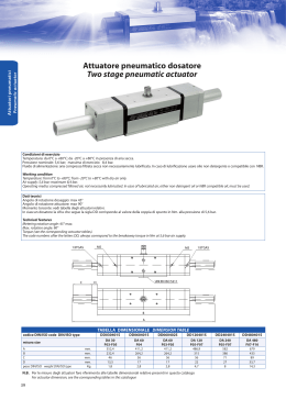
Attuatore pneumatico DOSATORE
versione DIN/ISO 5211 DIN 3337
Two stage pneumatic actuator
DIN/ISO 5211 DIN 3337
A1
CONDIZIONI DI ESERCIZIO
Temperatura: da 0°C a +80°C; da -20°C a +80°C in
presenza di aria secca.
Pressione nominale: 5,6 bar; massima di esercizio
8,4 bar.
Fluido di alimentazione: aria compressa filtrata secca
non necessariamente lubrificata. In caso di lubrificazione usare olio non detergente o compatibile con
NBR.
DATI TECNICI
1/8” ISO 228
1/8” ISO 228
Angolo di rotazione dosaggio: max 45°
Angolo di rotazione attuatore: max 90°
Momento torcente: vedi tabella degli attuatori relativi.
In ciascun dosatore la cifra che segue la sigla DD
corrisponde al valore della coppia di spunto in Nm.
alla pressione di 5,6 bar.
WORKING CONDITION
Temperature: from 0°C to +80°C; from -20°C to
+80°C with dry air only.
Air supply: 5,6 bar; maximum 8,4 bar.
Operating media: compressed filtered air, not necessarily lubricated.
In case of lubricated air, either non detergent oil or
NBR compatible oil, must be used.
TECHNICAL FEATURES
Metering rotation angle: 45° max.
Max. rotation angle: 90°
Torque (see the corresponding actuator tables).
The code numbers after the letters DD, always correspond to the breakaway torque in Nm at 5,6 bar air
supply.
TABELLA DIMENSIONALE DIMENSION TABLE
codice DIN/ISO code DIN/ISO type
misura size
A
B
C
D
peso DIN/ISO weight DIN/ISO type
mm.
mm.
mm.
mm.
Kg.
DD030401S
DA 30
352,4
232,4
46
13,5
1,8
DD060401S
DA 60
411,2
264,2
56
17
2,8
DD120401S
DA 120
486,9
212,9
56
22
4,7
DD240401S
DA 240
582
386
71
27
8
N.B. Per le misure degli attuatori fare riferimento alle tabelle dimensionali relative presenti in questo catalogo
For actuator dimension, see the corresponding tables in this catalogue
A1.17
DD480401S
DA 480
679
433
89
33,7
14,3
Schema di funzionamento Working plane
protezione
protection
protezione
protection
A1
corsa di regolazione
stroke adjustment
E2
corsa di regolazione
stroke adjustment
E1
CONDIZIONI GENERALI DI UTILIZZO E PRINCIPIO DI FUNZIONAMENTO GENERAL USE AND WORKING CONDITION
UTILIZZO:
Riempitura-Dosaggio di materie liquide o semisolide tramite il dispositivo di ponderazione.
Attuatore a doppia azione per dosaggi grossolani o fini.
ESECUZIONE:
Con attuatore a doppio effetto a norma DIN/ISO 5211 DIN 3337 oppure in esecuzione Standard.
USE:
Filling and metering of fluids or solids-mix materials by means of a special metering
device. Double acting actuator for fine or rough metering.
EXECUTION:
With DIN/ISO 5211 DIN 3337 or Standard double acting pneumatic actuator.
METODO DI LAVORO:
Il modello base é l’attuatore OMAL. Ad esso sono stati aggiunti due cilindri al cui
interno, i pistoni solidali ad un asta, la spingono longitudinalmente facendo da fermo
ai pistoni dell’attuatore impedendo così la completa rotazione del meccanismo ed
incidendo sulla portata totale della valvola. Il dispositivo funziona tramite le due elettrovalvole E1 = 5/2; E2 =3/2. Dove E1 comanda l’attuatore mentre E2 i due cilindri
esterni. Con riferimento alle elettrovalvole nel disegno vediamo alcuni esempi:
con VALVOLA TUTTA CHIUSA (0°) avremo:
E1: A in pressione B allo scarico; E2: B1 allo scarico.
Con VALVOLA TUTTA APERTA (90°) regolazione grossolana avremo:
E1: A allo scarico e B in pressione; E2: B1 allo scarico.
Al raggiungimento del valore previsto es. 90% del riempimento totale del contenitore, il segnale di grossolano (valvola tutta aperta) viene escluso e l’aria, passando
per E2 e successivamente cambiando la posizione di E1, raggiunge i pistoni esterni
i quali, muovendosi, eseguono l’angolo di chiusura desiderato, es. 30° (regolazione
fine), provocando così la riduzione voluta della portata.
Con VALVOLA APERTA es. 30° regolazione fine avremo:
E1: A in pressione B allo scarico; E2: B1 in pressione.
Questa posizione intermedia e la relativa portata della valvola verrà riprodotta con
assoluta fedeltà e precisione ad ogni ripetizione del procedimento.
N.B. la regolazione voluta può variare da 0° a 45° tramite il controdado D.
Quando il valore teorico combacerà con quello effettivo, verrà escluso il segnale di
regolazione fine che si trova su E2 (B1 allo scarico); l’attuatore comincerà a muoversi ottenendo così la chiusura totale della valvola. Con ciò è da ritenersi concluso il
procedimento di Riempitura-Dosaggio.
WORKING SYSTEM:
The basic model consists of an Omal double acting actuator, equipped with two
additional cylinders whose inner-pistons, by means of a stroke adjustment device,
stop the rotating angle of the actuator to a pre-set position, preventing it from a complete rotation and influencing the total valve flow pressure.
This device is driven by two solenoid valves.
E1 = 5/2; E2 =3/2. E1 drives the actuator, while E2 drives the two external cylinders.
Some examples referring to the valves in the drawing above:
- with a completely CLOSED VALVE (0°) You will have:
E1: air supply in A, exhausts in B
E2: exhausts in B1.
- with a completely OPEN VALVE (90°) rough metering You will have:
E1: exhausts in A, air supply in B
E2: exhausts in B1.
When You reach the desired level, e.g. 90% of the total filling, the rough signal (completely open valve) will turn off and the air, flowing through E2 and then changing
the position of E1, will get to the external pistons which will move to the desired
rotating angle, e.g. 30° (fine metering), consequently reducing the total valve flow..
With an OPEN VALVE, e.g. 30° fine metering, You will have:
E1: air supply in A, exhaust in B;
E2: air supply in B1
This intermediate position and the corresponding valve flow pressure will be reproduced, whenever you repeat the process.
NOTE: Thanks to control “D”, the desired metering can range from 0° to 45°.
When the desired level is the same as the actual one, the fine-metering signal on E2
(exhaust in B1) will turn off; the actuator will start moving and make the valve close,
completely. Now the filling and metering process is over.
IN CONCLUSIONE:
Il dispositivo OMAL può essere installato ovunque sia richiesto di fornire esattamente le stesse quantità per lunghi cicli di lavoro.
CONCLUSION:
“OMAL” device can be assembled wherever you need to furnish exactly the same
quantities in long working cycles.
A1.18
Attuatore pneumatico doppio effetto “DA”
Double acting pneumatic actuator “DA” type
SCHEMA DI FUNZIONAMENTO WORKING PLANE
foro hole A
A1
foro hole B
presa per valvola valve drive
presa per valvola valve drive
Immettendo aria nel foro A di alimentazione, i pistoni si muovono
verso il centro e si ha una rotazione antioraria, la posizione finale è
quella rappresentata nel disegno
Immettendo aria nel foro B di alimentazione, i pistoni si muovono
verso l’esterno e si ha una rotazione oraria, la posizione finale è
quella rappresentata nel disegno
Supplying air through the air connection A, the pistons move
towards the center in an anticlockwise direction. The above drawing
shows the final position.
Supplying air through the air connection B, the pistons move
outwards in a clockwise direction. The above drawing shows the
final position.
ATTUATORE CON REGOLAZIONE-ISTRUZIONI PER L’ UTILIZZO ACTUATOR WITH STROKE ADJUSTMENT-INSTRUCTIONS
tappo cap
A) Immettere aria nel foro “D” in modo che i pistoni
(part. n°1) si vengano a trovare in posizione di finecorsa verso i tappi.
B) Togliere il controdado (part. n°3) agendo sulla chiave C.
C) Togliere l’aria di alimentazione.
D) Con una chiave a brugola agire sulle viti (part. n°2)
ed effettuare la regolazione desiderata.
N.B. la regolazione standard arriva ad un massimo di
10° da 80° a 90°.
Altre regolazioni disponibili a richiesta.
E) Mettere aria nel foro “D”, verificare che entrambe le
viti (part. n°2) siano a battuta contro i pistoni.
F) Mettere il controdado (part. n°3) munito di O-ring
(part. n°4) per la tenuta tra dado e tappo.
tappo cap
chiave key C
A1.19
A) Supply air through the air connection D so that the
pistons (Part. 1) move to the end-stroke position,
towards the caps.
B) Remove the counter nut (part. 3) acting on the C
key.
C) Shut off the air supply.
D) Adjust the end stroke as desired, acting on the
screws (part 2) with an hexagonal key.
Note: maximum adjusting stroke 10°, ranging from 80°
to 90°.
Other regulations on request.
E) Supply air through the air connection D and check
that both screws stop the pistons.
F) Screw the counter-nut (part 3) and its o-ring (part 4)
to keep nut and cap tight.
Attuatore pneumatico semplice “SR”
Spring return pneumatic actuator “SR” type
SCHEMA DI FUNZIONAMENTO WORKING PLANE
foro hole A1
A1
foro hole B1
presa per valvola valve drive
presa per valvola valve drive
Senza pressione di alimentazione, nella versione semplice effetto, l’attuatore torna automaticamente in posizione di riposo compiendo una
rotazione oraria e la posizione finale è quella rappresentata nel disegno. Sul foro A1 è consigliato montare un filtrino onde evitare che polvere o particelle solide possano entrare nella camera del cilindro.
Immettendo aria nel foro B1 di alimentazione, i pistoni si muovono
verso l’esterno comprimendo le molle, si ha una rotazione antioraria e
la posizione finale è quella rappresentata nel disegno
Without air supply, the spring return actuator returns to its resting position, rotating in a clockwise direction. The drawing shows its final position.
We suggest assembling a small filter on the air connection A1 to prevent dust and particles from getting into the cylinder chamber.
Supplying air through the air connection B1, the pistons move
outwards pressing the springs. An anticlockwise rotation takes place
and the final position is shown above.
ATTUATORE CON REGOLAZIONE-ISTRUZIONI PER L’ UTILIZZO ACTUATOR WITH STROKE ADJUSTMENT-INSTRUCTIONS
tappo cap
tappo cap
A) Verificare che le molle siano in posizione di riposo
osservando la chiave dell’albero (part. n°1) come da
disegno e controllando che nel foro “D” non ci sia pressione.
B) Togliere i controdadi (part. n°2) agendo sulla chiave
C.
C) Con un cacciavite avvitare le viti (part. n°3) in senso
orario ed effettuare la regolazione desiderata.
N.B. la regolazione arriva ad un massimo di 10° da
80° a 90°.
D) Immettere aria nel foro “D” e verificare che entrambe le viti (part. n°3) siano a battuta contro i pistoni
(part. n°5).
E) Bloccare i controdadi (part. n°2) muniti di O-ring
(part. n°4) per la tenuta tra controdado, tappo e vite.
A) The springs must be at rest position, the shaft (part.
1) must be as shown in the drawing. Air connection D
must not be supplied with air.
chiave key C
B) Remove the counter-nuts (part. 2), acting on C key.
C) By means of a screwdriver turn screws (part. 3) in a
clockwise direction until you obtain the requested endstroke regulation.
Note: maximum adjusting stroke 10°, ranging from 80°
to 90°.
D) Supply connection D with air pressure and check
that both adjusting screws (part. 3) stop the pistons
(part. 5).
E) Screw the counter-nuts (part. 2) and their O-ring
(part. 4) to keep nut and cap tight.
A1.20
Scaricare