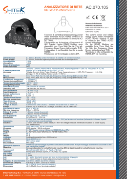
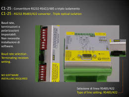
140 CONVERTITORI DI MISURA MEASUREMENT TRANSDUCERS Generalità 142 General characteristics CONVERTITORI DI MISURA 142 MEASUREMENT TRANSDUCERS Convertitori di Corrente 143 Current transducers Convertitori di Tensione 143 Voltage transducers Convertitori del Fattore di Potenza 144 Power Factor transducers Convertitori di Potenza Attiva o Reattiva Monofase 145 Single-phase Active or Reactive Power transducers Convertitori di Potenza Attiva o Reattiva Trifase - 3 fili 146 Three-phase Active or Reactive Power transducers - 3 wires Convertitori di Potenza Attiva o Reattiva Trifase - 4 fili 147 Three-phase Active or Reactive Power transducers - 4 wires CONVERTITORI DI MISURA - Vero valore efficace 148 MEASUREMENT TRANSDUCERS - True RMS CONVERTITORI DI MISURA PER CC 149 DC MEASUREMENT TRANSDUCERS Convertitori di Corrente 149 Current transducers Convertitori di Tensione 150 Voltage transducers CONCENTRATORE DISPOSITIVI RS485 152 RS485 CONCENTRATOR Esempio di utilizzo gruppo di misura remoto 153 Example of remote measurement group use 141 CONVERTITORI DI MISURA MEASUREMENT TRANSDUCERS Il convertitore di misura è un dispositivo che assicura l’acquisizione centralizzata dei dati in modo veloce ed affidabile anche a distanza, soddisfacendo la crescente necessità di tenere sotto controllo la produzione, la distribuzione e l’utilizzazione dell’energia elettrica. Forniscono in uscita un segnale in corrente continua indipendente dal carico (corrente impressa) direttamente proporzionale al segnale di ingresso. Un circuito elettronico accuratamente concepito, conferisce ai convertitori Revalco una grande affidabilità di funzionamento cui consegue una alta linearità, elevata precisione, esteso campo di misura, insensibilità alle variazioni di temperatura ed alle vibrazioni, ridotto assorbimento di potenza dal circuito sotto misura. I convertitori Revalco sono realizzati in modo che tutte le principali uscite richieste dal mercato siano già presenti in ciascuno di essi, lasciando al cliente la possibilità di scegliere l’uscita necessaria al momento, semplicemente variando la disposizione dei minidip presenti sotto lo sportello posto nella parte superiore della custodia. Norme: EN61010-1; EN60688; EN61000-6-4; EN61000-6-2 The transducer is a device that measures a given electrical parameter, which is then through electronic circuitry, converted to a DC signal, which is directly proportional to the input, to allow remote indication without loss of accuracy. The Revalco range of transducers, having galvanic separation between Input and Output, has been developed to a high specification giving the user, confidence with the Accuracy and Linearity over a wide range of measured parameters. Having Low Power Consumption while being unaffected by any changes in Temperature, Vibration or Load, ensures this range is suitable for many applications in the Power Monitoring and Distribution fields. Revalco transducers have been designed with the ever changing needs of the market in mind. Each item has incorporated the ability to select any of the recognised outputs of both DC mA and DC V by simple selection of minidip keys located under a removable section of the upper case wall Standards: EN61010-1; EN60688; EN61000-6-4; EN61000-6-2 % OUTPUT DATI PER ORDINARE ORDERING DATA The three phase active and reactive power transducers are calibrated with the following standard values: % INPUT 0 50 100 Current input 5A and the primary values are selectable by minidips Voltage input 400V On request it is possible to calibrate the transducers with the following parameters which must be indicated when ordering: Current input 1A % OUTPUT Voltage input: 100/√3/V, 110/√3V, 100V, 110V, 230V, 440V, 500V 100 % OUTPUT % OUTPUT When ordering, the end scale value must be indicated 60 100 100 100 100 50 50 100 100 0 50 50 0 OS % INPUT % INPUT 20 20 % INPUT % INPUT OSD DS 100 100 5050 100 50 100 % INPUT 100 130 50 70100 00 INPUT %% INPUT Onda sinusoidale, fattore di forma 1,11 Onda sinusoidale parzializzata (SCR) Sinusoidal wave, factor form 1,11 Partial sinusoidal wave form (SCR) % OUTPUT 50 70 70 0 50 50 0 0 50 50 100 100 50- 20 - 20 - 20 - 20 % INPUT 100 100 % INPUT 70 100 130 % INPUT 0 0 Onda sinusoidale distorta Doppia semionda 0 -100-100 50 % OUTPUT 100 50 % OUTPUT % OUTPUT 100 100 -100 0 60 100 130 130 % INPUT % INPUT Onda % INPUTquadra 100 Double half-wave form 100 % INPUT D1 100 100 %% OUTPUT OUTPUT % OUTPUT 50 50 100 100 100 100 6050 100 20 0 5050 50 50 100 100 INPUT - 200 %% INPUT 70 130 - 20 %% INPUT 0 0 5050 100 INPUT % INPUT 0 100 50 100 130 0 100 % INPUT D2 -100 100 0 100 0 0 D3 % OUTPUT 50 100 1005050100 100 130 70 100 100 % INPUT 0 0 % INPUT % INPUT 0 100 2020 20 -100-100 %% INPUT INPUT 100 % INPUT -100 % OUTPUT 100 100 100 D4 60 - 30 - 300 0 100 100 100 100 20 0 50 % INPUT % INPUT % INPUT -100 100 100 00 -100 -100 -100 130 70 70 100 130 % INPUT 100 20 0 60 %%OUTPUT OUTPUT 100 100 100 -100-100 0 0 -50 -50 5050 0 50 50 % INPUT % INPUT 50 100 100 50 100 % INPUT - 20 -50 - 20-50 70 130 100 0 0 % INPUT 130100 130 % INPUT 0 70 100 70 % INPUT -100-100 100 D7 %%OUTPUT OUTPUT %%INPUT INPUT 0 50 50 00 50 5 - 20 - 20 -50 -50 -100 -100 D9 OUTPUT %% OUTPUT %% OUTPUT OUTPUT % OUTPUT 100 100 100 % INPUT 100 100 100 50 6060 60 100 100 -100 100 100 INPUT %% INPUT INPUT 70 130 % INPUT 130100%130 100 % INPUT 70 0 70100 -50 0 % INPUT % INPUT 0 0 100 50 100 100 130 7070 130% INPUT 130 70 %% INPUT 0 0 100 INPUT 100 % INPUT 0 -50 100 -100 -100 100 % INPUT -100 -100 -1000 0 - 30 0 0 100 INPUT %% INPUT 100 INPUT 100 INPUT 100% % 0 100 % INPUT 0 % INPUT 50 20 % OUTPUT Torsion value of screws M4 is 2,0 Nm. 100 Torsion value of screws M3 is 0,5 Nm. 20 -100 -50-50 -100-100 -100 100 % INPUT -500 0 00 0 0 %INPUT INPUT 100 5050 % 100 % INPUT 50 100 %INPUT INPUT % 100 100 50 50 -50 -100 -100 -100 100 100 100 6060 60 50 0 0 -100 -100 0 2020 INPUT INPUT % INPUT 0 100 % INPUT 50100 100100% % -100 -100 -100 -1000 0 0 - 30 - 30 - 30 0 0- 30 100 % INPUT %% INPUT INPUT 100 0100 % INPUT 100 % INPUT 20 100 50 100 0 %INPUT INPUT % -100 - 300 0 -100 % OUTPUT % OUTPUT % OUTPUT 100 100 100 60 50 0 100 % INPUT %% OUTPUT OUTPUT % OUTPUT 100 100 100 % OUTPUT 100 2020 20 100 0 100 100 0 -100 20 20 100 00 50 %% OUTPUT OUTPUT % OUTPUT 100 100100100 60 50 SCREWS TORQUE VALUES % OUTPUT %% OUTPUT OUTPUT % OUTPUT 100 100 100 100 -100 %% OUTPUT OUTPUT % OUTPUT % OUTPUT -50 -100 -50-50 100 100 0 50 % INPUT % INPUT -100 100 0 100 100 -50 % OUTPUT %OUTPUT OUTPUT % % OUTPUT %OUTPUT OUTPUT % 100 100 100 10060100 100 -100 20 20 - 30 - 300 -100 Il valore di torsione delle viti M4 è di 2,0 Nm. 50 20 5050 50 50 Il valore 50di50torsione delle viti M3 è di 0,5 Nm. OUTPUT %%OUTPUT 50 100 100 -100 COPPIA DI SERRAGGIO VITI MORSETTI OUTPUT %% OUTPUT %% OUTPUT OUTPUT % OUTPUT 100 100 100 100 100 50 % INPUT 00 100 100 % INPUT 100 % INPUT %% INPUT - 20 100 INPUT - 20 50 100 % INPUT - 205050 100 -100 - 20 - 20 - 20 0 00 -030 D13 % OUTPUT 100 %OUTPUT OUTPUT % 100 100 100 20 2050 5050 -100-100 D12 % OUTPUT % OUTPUT % OUTPUT 100 6010060 100 100 50 -100-100 D11 %% OUTPUT % OUTPUT OUTPUT %% OUTPUT OUTPUT % 100 OUTPUT 100 100 %% OUTPUT OUTPUT % 100 OUTPUT 100 100 -100 2020- 30 0 200 0 0 D10 %% OUTPUT % OUTPUT OUTPUT %% INPUT INPUT 100 % INPUT - 30 - 30 0 0- 30 20 100 0100 142 7 Square wave form % OUTPUT % OUTPUT 100 100 100 %% OUTPUT OUTPUT % OUTPUT 50 -50 0 -100 0 % INPUT % INPUT 70 100 130 100 Distorted sinusoidal wave form %% OUTPUT % OUTPUT OUTPUT 100 100 100 %% OUTPUT OUTPUT % OUTPUT % OUTPUT 50 % OUTPUT -100 -50 1000 100 50 20 20 0 0 % OUTPUT % OUTPUT % OUTPUT % OUTPUT OUTPUT %% OUTPUT 20 -100 0 % INPUT 100 100 100 100 20 20 20 % INPUT 70 130 100 130 % INPUT 0 0 70 100 100 % INPUT 0 100 0 OQ % OUTPUT % OUTPUT % OUTPUT % OUTPUT % OUTPUT 100 100 % OUTPUT 100 100 100 60 60 100 % INPUT 70 100 130 % OUTPUT % OUTPUT % OUTPUT OUTPUT %% OUTPUT % OUTPUT 50 70 130 70 100 100 130 % INPUT % INPUT 0 0 0 OSP 0 WAVEFORM AND LINEARITY DIAGRAMS BETWEEN INPUTS AND OUTPUTS 100 100 0 0 20 % OUTPUT % OUTPUT 20 100 0 50 50 FORME D’ONDA DI INGRESSO E DIAGRAMMI DELLA LINEARITA’ TRA INGRESSI ED USCITE 100 50 I convertitori trifase di potenza attiva e reattiva sono tarati con i seguenti valori standard: Ingresso in corrente 5A e primari selezionabili tramite minidip Ingresso in tensione 400V A richiesta è possibile tarare i convertitori con i seguenti parametri che andranno quindi indicati in fase d’ordine: Ingresso corrente 1A Ingresso tensione: 100/√3/V, 110/√3V, 100V, 110V, 230V, 440V, 500V % OUTPUT % OUTPUT % OUTPUT In fase d’ordine indicare anche il% OUTPUT fondo scala 100 100 % OUTPUT 100 %% INPUT INPUT 100 % INPUT 50 0 50 100 % INPUT 100 % INPUT % INPUT - 30 0 DIMENSIONI IN mm DIMENSIONS in mm 58 58 1 Modulo DIN 1 DIN Module 45 85 85 45 58 58 105 17,5 85 85 45 45 35 La dimensione 105 mm corrisponde a 6 moduli DIN The 105 mm dimension corresponds to 6 DIN modules La dimensione 35 mm corrisponde a 2 moduli DIN The 35 mm dimension corresponds to 2 DIN modules 52,5 La dimensione 52,5 mm corrisponde a 3 moduli DIN The 52,5 mm dimension corresponds to 3 DIN modules CONVERTITORI DI CORRENTE CURRENT TRANSDUCERS AUTOALIMENTATI SELF SUPPLIED 1CORIAA5 20 1CORIAA1 20 1CORIAA5 10 1CORIAA1 10 - VALORI NOMINALI DI INGRESSO / NOMINAL INPUT VALUES5A 1A 5A 1A - VALORI NOMINALI IN USCITA / NOMINAL OUTPUT VALUES 20 mA DC 20 mA DC 10 V DC 10 V DC - CARICO RESISTIVO / RESISTIVE LOAD300Ω300Ω>10kΩ>10kΩ - CAMPO DI MISURA / MEASURING RANGE 0 ÷ In - CLASSE DI PRECISIONE / ACCURACY CLASS1 - SOVRACCARICO / OVERLOAD Permanente / Permanent: 1,2 In Istantaneo / Instantaneous: 10 In 1 sec. - TEMPO DI RISPOSTA / RESPONSE TIME ≤ 300 ms - RESIDUO ALTERNATO / ALTERNATED RESIDUAL ≤ 2% - FREQUENZA DI FUNZIONAMENTO / OPERATING FREQUENCY 50/60 Hz - AUTOCONSUMO / BURDEN 3 VA - SEPARAZIONE GALVANICA TRA INGRESSI ED USCITE 2kV per 1min a 50Hz GALVANIC SEPARATION BETWEEN INPUTS AND OUTPUTS 2kV for 1min at 50Hz - TEMPERATURA DI FUNZIONAMENTO / OPERATING TEMPERATURE 0 °C ÷ +55 °C - FORME D’ ONDA DI INGRESSO / INPUT WAVE FORM OS - DIMENSIONI / DIMENSIONS 2 moduli DIN / 2 DIN modules - PESO / WEIGHT kg. 0,25 - Dati tecnici diversi da quelli indicati possono essere considerati su richiesta specifica Different technical characteristic can be considered, under specific requests (10V DC) 20 mA DC Signal input (A) CONVERTITORI DI TENSIONE VOLTAGE TRANSDUCERS AUTOALIMENTATI SELF SUPPLIED 1CORUAA 1CORUAA1CORUAA 1CORUAA1CORUAA1CORUAA 100 20 100R3 20 230 20 100 10 100R3 10 230 10 (10V DC) 20 mA DC - VALORI NOMINALI DI INGRESSO NOMINAL INPUT VALUES 100V100:√3V230V 100V100:√3V230V - VALORI NOMINALI IN USCITA NOMINAL OUTPUT VALUES 20 mA DC 20 mA DC 20 mA DC 10 V DC 10 V DC 10 V DC - CARICO RESISTIVO300Ω300Ω300Ω>10kΩ>10kΩ>10kΩ - CAMPO DI MISURA / RESISTIVE LOAD 0 ÷ In - CLASSE DI PRECISIONE / MEASURING RANGE1 - SOVRACCARICO / ACCURACY CLASS Permanente / Permanent: 1,2 In Istantaneo / Instantaneous: 10 In per 1 sec. - TEMPO DI RISPOSTA / RESPONSE TIME ≤ 300 ms - RESIDUO ALTERNATO / ALTERNATED RESIDUAL ≤ 2% - FREQUENZA DI FUNZIONAMENTO / OPERATING FREQUENCY 50/60 Hz - AUTOCONSUMO / BURDEN 3 VA - SEPARAZIONE GALVANICA TRA INGRESSI ED USCITE 2kV per 1min a 50Hz GALVANIC SEPARATION BETWEEN INPUTS AND OUTPUTS 2kV for 1min at 50Hz Signal input (V) - TEMPERATURA DI FUNZIONAMENTO / OPERATING TEMPERATURE 0 °C ÷ +55 °C - FORME D’ ONDA DI INGRESSO / INPUT WAVE FORM OS - DIMENSIONI / DIMENSIONS 2 moduli DIN / 2 DIN modules - PESO / WEIGHT kg. 0,25 - Dati tecnici diversi da quelli indicati possono essere considerati su richiesta specifica Different technical characteristic can be considered, under specific requests 143 CONVERTITORI DEL FATTORE DI POTENZA POWER FACTOR TRANSDUCERS ALIMENTAZIONE SEPARATA EXTERNAL AUXILIARY SUPPLY Convertitore provvisto di separazione galvanica tra ingressi ed uscite, e dalla possibilità di selezionare l’uscita necessaria al momento tra le otto previste (±1, ±5, ±10 VCC e ±1, ±5, ±10, ±20, 4/20 mA CC). E’ anche possibile selezionare il tipo di conversione necessario tra: - proporzionale all’angolo di fase, con l’uscita da 1 mA CC (in gradi) per l’inserzione con uno strumento lettore analogico. - proporzionale al cos φ con l’uscita da ±1, ±5, ±10, ±20, 4/20 mA e ±1, ±5, ±10 V per tutti gli altri usi The transducer have galvanic separation between inputs and outputs and the capability to offer multiple choice by terminal selection and 8 outputs (±1, ±5, ±10 VDC and ±1, ±5, ±10, ±20, 4/20 mA DC). It is also possible to select the required conversion between: - proportional to the phase angle, with output 1mA DC (in degrees) for connection with an analogue measuring instrument. - proportional to cos φ with output ±1, ±5, ±10, ±20, ±4/20 mA and ±1, ±5, ±10 V for all other use 1CORFP10 Monofase / Single phase 1CORFP20 Trifase, equilibrato a 3 fili / Three phase, balanced load, 3 wires - ALIMENTAZIONE AUSILIARIA (separata) AUXILIARY SUPPLY (separate) 230V AC standard 230V / 400V AC standard - VALORI NOMINALI DI INGRESSO tensione: 230V AC 50/60 Hz tensione: 400V AC 50/60 Hz corrente: 5A (1A nei modelli 1CORFP...B) corrente: 5A (1A nei modelli 1CORFP...B) NOMINAL INPUT VALUES VOLTAGE 230V AC 50/60 Hz 400V AC 50/60 Hz current: 5A (1A on 1CORFP...B type) current: 5A (1A on 1CORFP...B type) - VALORI NOMINALI IN USCITA (selezionabili) NOMINAL OUTPUT VALUES (selectable) ±1, ±5, ±10 VDC ±1, ±5, ±10, ±20, 4/20 mA DC - CARICO RESISTIVO / RESISTIVE LOAD 700Ω max - CLASSE DI PRECISIONE / ACCURACY CLASS0,5 - CAMPO DI MISURA / MEASURING RANGE 0,5 (cap) - 1 - 0,5 (ind) standard - SOVRACCARICO / OVERLOAD Permanente / Permanent: 2 In / 1,2 Un - Istantaneo / Instantaneous: 10 In / 2 Un per 1 sec - TEMPO DI RISPOSTA / RESPONSE TIME ≤ 300 ms - RESIDUO ALTERNATO / ALTERNATED RESIDUAL ≤ 1% - AUTOCONSUMO / BURDEN tensione / voltage circuit ≤ 1VA corrente / current circuit ≤ 0,8VA alim. ausiliaria / power supply ≤ 4VA - SEPARAZIONE GALVANICA TRA INGRESSI ED USCITE isolamento tra ingressi, uscite, alimentazione aux 2kV per 1min a 50Hz isolamento tra tutti i circuiti e la massa: 4kV per 1min a 50Hz - GALVANIC SEPARATION BETWEEN INPUTS AND OUTPUTS insulation between inputs, outputs, power supply 2kV for 1min at 50Hz insulation between the all circuits and earth 4kV for 1min at 50Hz 0 °C ÷ +55 °C - TEMPERATURA DI FUNZIONAMENTO/ OPERATING TEMPERATURE - FORME D’ ONDA DI INGRESSO / INPUT WAVE FORM OS - OSD (schemi / schemes D10, D2) - DIMENSIONI / DIMENSIONS 6 moduli DIN / 6 DIN modules 0,50 - PESO / WEIGHT kg. USCITE SOLO POSITIVE SELEZIONABILI - Dati tecnici diversi da quelli indicati possono essere considerati su richiesta specifica Different technical characteristic can be considered, under specific requests 1CORFP10 1CORFP20 La selezione delle uscite deve essere eseguita spostando i minidip in funzione della necessità del momento, secondo il seguente schema: se é stata selezionata una uscita in Volt, é necessario collegare i morsetti n°13 e n°15; mentre é necessario collegare i morsetti n°13 e n°14 se l’uscita selezionata é in milliampére. Per alimentare lo strumento a 230V collegare il morsetto comune n°22 ed il morsetto n°23; mentre per alimentarlo a 400V collegare il morsetto comune n°22 ed il morsetto n°24. The selection of the required output is achieved by adjusting the minidip keys as described in the following diagram: where a Voltage output is required connection is by terminal Nos, 13 and 15 and for Current output connect to terminal Nos, 13 and 14. The auxiliary Power Supply is achieved by: use terminal 22 as the common connection; for 230V USCITE POSITIVE E NEGATIVE SELEZIONABILI connect to Terminal 23; for 400V connect to Terminal 24 SELECTABLE POSITIVE ONLY OUTPUTS 230V 4÷20, ±20, ±10, ±5, ±1 mA DC C ±10, ±5, ±1 V DC 400V SELECTABLE POSITIVE AND NEGATIVE OUTPUTS I- C+ V- 13 14 15 20 2 8 1 5A L1 N N S1 S2 P1 P2 22 23 24 SIGNAL CONVERSION SELECTION SELEZIONE CONVERSIONE SEGNALE V proportional phase angle proportional cosϕ all'angolo di fase proporzionaletoal cosϕ CONVERSIONproporzionale SIGNAL SELECTION to Output forinserzione insertion Output forinserzione insertion Uscitainindegree, gradi, per Uscitainindegree, gradi, per withstrumento analoguelettore instrument withstrumento analoguelettore instrument con analogico con analogico not linear divisions linear divisions andamento scala non lineare andamento scala lineare proportional to phase angle Output in degree, for insertion with analogue instrument not linear divisions proportional to cosϕ Output in degree, for insertion with analogue instrument linear divisions 144 CONVERTITORI DI POTENZA ATTIVA O REATTIVA MONOFASE SINGLE PHASE ACTIVE OR REACTIVE POWER TRANSDUCERS ALIMENTAZIONE SEPARATA EXTERNAL AUXILIARY SUPPLY Convertitore provvisto di separazione galvanica tra ingressi ed uscite, caratterizzato dalla possibilità di essere alimentato sia a 230V che a 400V collegando gli appositi morsetti, e dalla possibilità di selezionare l’uscita necessaria al momento, tra le otto previste (1-5-10 VCC e 1-5-10-20-4/20 mA CC), semplicemente selezionandola tramite il minidip incorporato. Di serie la taratura viene così fornita: 100V, 5A = 500 W (var); 230V, 5A = 1000 W (var); 400V, 5A = 2000 W (var) These transducers have the galvanic separation between inputs and outputs, and have the capability to offer multiple choice auxiliary supply of ( 230V, 400V) by terminal selection and 8 Outputs (1-5-10 VDC and 1-5-10-20-4/20 mA DC), by minidip key located under a removable section of the upper case wall and by terminal selection. The standard calibration is: 100V, 5A = 500 W (var); 230V, 5A = 1000 W (var); 400V, 5A = 2000 W (var) Potenza Attiva / Active Power Potenza Reattiva / Reactive Power 1CORPA101CORPA10485 1CORPR10 1CORPR10485 • • - Uscite selezionabili valori positivi e negativi / SELECTABLE BIDIRECTIONAL OUTPUTS - Uscite selezionabili valori positivi e negativi con uscita seriale RS485 SELECTABLE BIDIRECTIONAL OUTPUTS WITH serial OUTPUT RS485 • - PROTOCOLLO MODBUS SLAVE RTU / MODBUS SLAVE RTU PROTOCOL • - VALORI NOMINALI IN USCITA (selezionabili) / NOMINAL OUTPUT VALUES (selectable) ±1, ±5, ±10 VDC ±1, ±5, ±10, ±20, 4/20 mADC - ALIMENTAZIONE AUSILIARIA (separata) / AUXILIARY SUPPLY (separate) 230V / 400V CA standard - VALORI NOMINALI DI INGRESSO / NOMINAL INPUT VALUES tensione / voltage: 230V standard - corrente / current: 5A (1A su richiesta / on request ) - CARICO RESISTIVO / RESISTIVE LOAD 700Ω max - CAMPO DI MISURA / MEASURING RANGE 0 ÷ Pn (0 ÷ Qn) - TARATURA STANDARD / STANDARD CALIBRATION 100V,5A=500W (var) 230V,5A=1000W (var) 400V,5A=2000W (var) - CLASSE DI PRECISIONE / ACCURACY CLASS 0,5 - FREQUENZA DI FUNZIONAMENTO / OPERATING FREQUENCY 50 - 60 Hz - SOVRACCARICO / OVERLOAD Permanente / Permanent : 2 In / 1,2 Un Istantaneo / Instantaneous : 10 In / 2 Un per 1 sec. - TEMPO DI RISPOSTA / RESPONSE TIME ≤ 300 ms - RESIDUO ALTERNATO / ALTERNATED RESIDUAL ≤ 1% - AUTOCONSUMO / BURDEN tensione / voltage circuit ≤ 1VA corrente / current circuit ≤ 0,8VA alim. ausiliaria / power supply ≤ 4VA - SEPARAZIONE GALVANICA TRA INGRESSI ED USCITE isolamento tra ingressi, uscite, alimentazione aux 2kV per 1min a 50Hz isolamento tra tutti i circuiti e la massa: 4kV per 1min a 50Hz - GALVANIC SEPARATION BETWEEN INPUTS AND OUTPUTS insulation between inputs, outputs, power supply 2kV for 1min at 50Hz insulation between the all circuits and earth 4kV for 1min at 50Hz - TEMPERATURA DI FUNZIONAMENTO/ OPERATING TEMPERATURE 0 °C ÷ +55 °C - FORME D’ ONDA DI INGRESSO / INPUT WAVE FORM OS - OSD (schemi / schemes D10, D2) - DIMENSIONI / DIMENSIONS 6 moduli DIN / 6 DIN modules - PESO / WEIGHT kg. 0,50 USCITE SOLO POSITIVE SELEZIONABILI - Dati tecnici diversi da quelli indicati possono essere considerati su richiesta specifica. Il software é fornito gratuitamente sul nostro sito internet www.revalco.it Different technical characteristic can be considered, under specific requests. The software is available, free of charge, on our internet address www.revalco.it 1CORPA10 / 1CORPR10 1CORPA10485 / 1CORPR10485 La selezione delle uscite deve essere eseguita spostando i minidip in funzione della necessità del momento, secondo il seguente schema: se é stata selezionata una uscita in Volt, é necessario collegare i morsetti n°13 e n°15; mentre é necessario collegare i morsetti n°13 e n°14 se l’uscita selezionata é in milliampére. Per alimentare lo strumento a 230V collegare il morsetto comune n°22 ed il morsetto n°23; mentre per alimentarlo a 400V collegare il morsetto comune n°22 ed il morsetto n°24. The selection of the required output is achieved by adjusting the minidip keys as described in the following diagram: where a Voltage output is required connection is by terminal Nos, 13 and 15 and for Current output connect to terminal Nos, 13 and 14. The auxiliary Power Supply is achieved by: use terminal 22 as the common connection; 230V SELEZIONABILI connect to Terminal 23; for 400V connect to Terminal 24 USCITE POSITIVE E for NEGATIVE SELECTABLE POSITIVE ONLY OUTPUTS I- C+ N 20 2 8 5A L1 N SELECTABLE POSITIVE AND NEGATIVE OUTPUTS V- 13 14 15 1 S1 S2 P1 P2 ±10, ±5, ±1 V DC 400V I- C+ V- 13 14 15 22 23 24 2 1 5A V L1 N 145 S1 S2 P1 P2 230V C 400V RS485 C ±10, ±5, ±1 V DC 4÷20, ±20, ±10, ±5, ±1 mA DC 230V 4÷20, ±20, ±10, ±5, ±1 mA DC 17 18 N 20 22 23 24 8 12 V CONVERTITORI DI POTENZA ATTIVA O REATTIVA TRIFASE 3 FILI THREE PHASE ACTIVE OR REACTIVE POWER TRANSDUCERS 3 WIRES ALIMENTAZIONE SEPARATA EXTERNAL AUXILIARY SUPPLY Convertitore provvisto di separazione galvanica tra ingressi ed uscite, caratterizzato dalla possibilità di essere alimentato sia a 230V che a 400V collegando gli appositi morsetti, e dalla possibilità di selezionare l’uscita necessaria al momento, tra le otto previste (1-5-10 VCC e 1-5-10-20-4/20 mA CC), semplicemente selezionandola tramite il minidip incorporato. Di serie la taratura viene così fornita: 100V, 5A = 1000 W (var); 230V, 5A = 2000 W (var); 400V, 5A = 4000 W (var) These transducers have the galvanic separation between inputs and outputs, and have the capability to offer multiple choice auxiliary supply of ( 230V, 400V) by terminal selection and 8 Outputs (1-5-10 VDC and 1-5-10-20-4/20 mA DC), by minidip key located under a removable section of the upper case wall and by terminal selection. The standard calibration is: 100V, 5A = 1000 W (var); 230V, 5A = 2000 W (var); 400V, 5A = 4000 W (var) Sistema equilibrato Sistema non equilibrato senza neutro senza neutro (Aron) Balanced load Unbalanced load without neutral without neutral (Aron) 1CORPA201CORPA20485 1CORPA30 1CORPA30485 1CORPR201CORPR20485 1CORPR30 1CORPR30485 Potenza Attiva / Active Power Potenza Reattiva / Reactive Power - Uscite selezionabili valori positivi e negativi SELECTABLE BIDIRECTIONAL OUTPUTS • • • • - Uscite selezionabili valori positivi e negativi con uscita seriale RS485 SELECTABLE BIDIRECTIONAL OUTPUTS WITH serial OUTPUT RS485 • • - PROTOCOLLO MODBUS SLAVE RTU / MODBUS SLAVE RTU PROTOCOL • • - VALORI NOMINALI IN USCITA (selezionabili) / NOMINAL OUTPUT VALUES (selectable) ±1, ±5, ±10 VDC ±1, ±5, ±10, ±20, 4/20 mADC - ALIMENTAZIONE AUSILIARIA (separata) / AUXILIARY SUPPLY (separate) 230V / 400V AC standard - VALORI NOMINALI DI INGRESSO / NOMINAL INPUT VALUES tensione / voltage : 400V standard - corrente / current : 5A (1A su richiesta / on request ) - CARICO RESISTIVO / RESISTIVE LOAD 700Ω max - CAMPO DI MISURA / MEASURING RANGE 0 ÷ Pn (0 ÷ Qn) - TARATURA STANDARD / STANDARD CALIBRATION 100V,5A=1000W (var) 230V,5A=2000W (var) 400V,5A=4000W (var) - CLASSE DI PRECISIONE / ACCURACY CLASS0,5 FREQUENZA DI FUNZIONAMENTO / OPERATING FREQUENCY 50 - 60 Hz - SOVRACCARICO / OVERLOAD Permanente / Permanent: 2 In / 1,2 Un - Istantaneo / Instantaneous: 10 In / 2 Un per 1 sec - TEMPO DI RISPOSTA / RESPONSE TIME ≤ 300 ms - RESIDUO ALTERNATO / ALTERNATED RESIDUAL ≤ 1% - AUTOCONSUMO / BURDEN tensione / voltage circuit ≤ 1VA corrente / current circuit ≤ 0,8VA alim. ausiliaria / power supply ≤ 4VA - SEPARAZIONE GALVANICA TRA INGRESSI ED USCITE isolamento tra ingressi, uscite, alimentazione aux 2kV per 1min a 50Hz isolamento tra tutti i circuiti e la massa: 4kV per 1min a 50Hz - GALVANIC SEPARATION BETWEEN INPUTS AND OUTPUTS insulation between inputs, outputs, power supply 2kV for 1min at 50Hz insulation between the all circuits and earth 4kV for 1min at 50Hz - FORME D’ ONDA DI INGRESSO / INPUT WAVE FORM OS - OSD (schemi / schemes D10, D2) - TEMPERATURA DI FUNZIONAMENTO/ OPERATING TEMPERATURE 0 °C ÷ +55 °C - DIMENSIONI / DIMENSIONS 6 moduli DIN / 6 DIN modules - PESO / WEIGHT kg. 0,50 - Dati tecnici diversi da quelli indicati possono essere considerati su richiesta specifica. Il software é fornito gratuitamente sul nostro sito internet www.revalco.it Different technical characteristic can be considered, under specific requests. The software is available, free of charge, on our internet address www.revalco.it 1CORPA20.... / 1CORPR20.... 1CORPA30.... / 1CORPR30.... POSITIVEdel SELEZIONABILI La selezione delle uscite deve essere eseguita spostando i minidip in funzioneUSCITE dellaSOLO necessità momento, secondo il seguente schema: se é stata selezionata una uscita in Volt, é necessario collegare i morsetti n°13 e n°15; mentre é necessario collegare i morsetti n°13 e n°14 se l’uscita selezionata é in milliampére. Per alimentare lo strumento a 230V collegare il morsetto comune n°22 ed il morsetto n°23; mentre per alimentarlo a 400V collegare il morsetto comune n°22 ed il morsetto n°24. The selection of the required output is achieved by adjusting the minidip keys as described in the following diagram: where a Voltage output is required connection is by terminal Nos, 13 and 15 and for Current output connect to terminal Nos, 13 and 14. The auxiliary Power Supply is achieved by: use terminal 22 as the common connection; for 230V connect to Terminal 23; for 400V connect to Terminal 24 1CORPA20 1CORPR20 V20 24÷20, ±20, ±10, ±5, ±1 mA 8DC ±10, ±5, ±1 V DC S2 P1 ±10, ±5, ±1 V DC 17 18 20 8 8 5A S1 S2 S1 P1 S2 P2 P1 P2 5A 10 12 12 V V L2 2 1 1CORPR20 / 1CORPR20485 5A L1 L2 L3 S1 S2 P1 P2 17 18 I- C+ 20 13 14 15 8 10 1 2 5 6 5A 5A V 1CORPA20 / 1CORPA20485 L1 L2 L3 146 4/20,±10, ±20,±5,±10, ±1 V±5,DC±1 mA DC ±10, ±5, ±1 V DC 400V 1CORPA30485 L2 1CORPR30485 V- 22 23 24 12 C ±10, ±5, ±1 V DC 400V SELECTABLE POSITIVE AND NEGATIVE OUTPUTS C S1 S2 S1 S2 P1 P2 P1 P2 20 22 23 24 8 12 V 1CORPR30 / 1CORPR30485 20 5A C+ S1I- S2 VC+ IV- L1 L2 L3 P1 P2 5A S1 S2 P1 P2 5A L1 L1 L2 L2 L3 L3 22 23 24 24/20, ±20, ±10, 5 ±5, 6 ±1 mA8DC 1 230V 4÷20, ±20, ±10, ±5, ±1 mA DC 22 23 24 13 14 15 2 2 230V 1CORPA20485 VC+ I1CORPR20485 V P2 13 14 15 1 1 L1 L1 L2 L2 L3 L3 V- 4÷20, ±20, ±10, ±5, ±1 mA DC 400V RS485 I- 230V 12 C V- 13 14 15 to terminal 20 L1 L2 L3 S1 10 I- C+ 22 23 24 RS485 5A C+ 1CORPA30 1CORPR30 SELECTABLE POSITIVE ONLY OUTPUTS 400V C ±10, ±5, ±1 V DC RS485 RS485 13 14 15 1 USCITE POSITIVE E NEGATIVE SELEZIONABILI to terminal 20 I- C+ 230V 4÷20, ±20, ±10, ±5, ±1 mA DC 400V C ±10, ±5, ±1 V DC 5A S1 5A S2 S1 5A S2 S1 P1 S2 P2 S1 P1 S2 P2 P1 P2 P1 P2 C C 230V12 230V 400V 400V V L2 L2 V V To terminal 20 To terminal 20 230V 4÷20, ±20, ±10, ±5, ±1 mA DC 1CORPA30 / 1CORPA30485 CONVERTITORI DI POTENZA ATTIVA O REATTIVA TRIFASE 4 FILI THREE PHASE ACTIVE OR REACTIVE POWER TRANSDUCERS 4 WIRES ALIMENTAZIONE SEPARATA EXTERNAL AUXILIARY SUPPLY Convertitore provvisto di separazione galvanica tra ingressi ed uscite, caratterizzato dalla possibilità di essere alimentato sia a 230V che a 400V collegando gli appositi morsetti, e dalla possibilità di selezionare l’uscita necessaria al momento, tra le otto previste (1-5-10 VCC e 1-5-10-20-4/20 mA CC), semplicemente selezionandola tramite il minidip incorporato. Di serie la taratura viene così fornita: 100V, 5A = 1000 W (var); 230V, 5A = 2000 W (var); 400V, 5A = 4000 W (var) These transducers have the galvanic separation between inputs and outputs, and have the capability to offer multiple choice auxiliary supply of ( 230V, 400V) by terminal selection and 8 Outputs (1-5-10 VDC and 1-5-10-20-4/20 mA DC), by minidip key located under a removable section of the upper case wall and by terminal selection. The standard calibration is: 100V, 5A = 1000 W (var); 230V, 5A = 2000 W (var); 400V, 5A = 4000 W (var) Sistema equilibrato Sistema non equilibrato con neutro con neutro Balanced load Unbalanced load with neutral with neutral 1CORPA401CORPA40485 1CORPA50 1CORPA50485 1CORPR401CORPR40485 1CORPR50 1CORPR50485 Potenza Attiva / Active Power Potenza Reattiva / Reactive Power - Uscite selezionabili valori positivi e negativi SELECTABLE BIDIRECTIONAL OUTPUTS • • • • - Uscite selezionabili valori positivi e negativi con uscita seriale RS485 SELECTABLE BIDIRECTIONAL OUTPUTS WITH serial OUTPUT RS485 • • - PROTOCOLLO MODBUS SLAVE RTU / MODBUS SLAVE RTU PROTOCOL • • - VALORI NOMINALI IN USCITA (selezionabili) / NOMINAL OUTPUT VALUES (selectable) ±1, ±5, ±10 VDC ±1, ±5, ±10, ±20, 4/20 mADC - ALIMENTAZIONE AUSILIARIA (separata) / AUXILIARY SUPPLY (separate) 230V / 400V AC standard tensione / voltage : 400V standard - corrente / current : 5A (1A su richiesta / on request ) - VALORI NOMINALI DI INGRESSO / NOMINAL INPUT VALUES - CARICO RESISTIVO / RESISTIVE LOAD 700Ω max - CAMPO DI MISURA / MEASURING RANGE 0 ÷ Pn (0 ÷ Qn) - TARATURA STANDARD / STANDARD CALIBRATION 100V,5A=1000W (var) 230V,5A=2000W (var) 400V,5A=4000W (var) - CLASSE DI PRECISIONE / ACCURACY CLASS0,5 FREQUENZA DI FUNZIONAMENTO / OPERATING FREQUENCY 50 - 60 Hz - SOVRACCARICO / OVERLOAD Permanente / Permanent: 2 In / 1,2 Un - Istantaneo / Instantaneous: 10 In / 2 Un per 1 sec - TEMPO DI RISPOSTA / RESPONSE TIME ≤ 300 ms - RESIDUO ALTERNATO / ALTERNATED RESIDUAL ≤ 1% - AUTOCONSUMO / BURDEN tensione / voltage circuit ≤ 1VA corrente / current circuit ≤ 0,8VA alim. ausiliaria / power supply ≤ 4VA - SEPARAZIONE GALVANICA TRA INGRESSI ED USCITE isolamento tra ingressi, uscite, alimentazione aux 2kV per 1min a 50Hz isolamento tra tutti i circuiti e la massa: 4kV per 1min a 50Hz - GALVANIC SEPARATION BETWEEN INPUTS AND OUTPUTS insulation between inputs, outputs, power supply 2kV for 1min at 50Hz insulation between the all circuits and earth 4kV for 1min at 50Hz - FORME D’ ONDA DI INGRESSO / INPUT WAVE FORM OS - OSD (schemi / schemes D10, D2) - TEMPERATURA DI FUNZIONAMENTO/ OPERATING TEMPERATURE 0 °C ÷ +55 °C - DIMENSIONI / DIMENSIONS 6 moduli DIN / 6 DIN modules - PESO / WEIGHT kg. 0,50 - Dati tecnici diversi da quelli indicati possono essere considerati su richiesta specifica. Il software é fornito gratuitamente sul nostro sito internet www.revalco.it Different technical characteristic can be considered, under specific requests. The software is available, free of charge, on our internet address www.revalco.it 1CORPA40.... / 1CORPR40.... 1CORPA50.... / 1CORPR50.... La selezione delle uscite deve essere eseguita spostando i minidip in funzione della necessità del momento, secondo il seguente schema: se é stata selezionata una uscita in Volt, é necessario collegare i morsetti n°13 e n°15; mentre é necessario collegare i morsetti n°13 e n°14 se l’uscita selezionata é in milliampére. USCITE SOLO POSITIVE SELEZIONABILI Per alimentare lo strumento a 230V collegare il morsetto comune n°22 ed il morsetto n°23; mentre per alimentarlo a 400V collegare il morsetto comune n°22 ed il morsetto n°24. The selection of the required output is achieved by adjusting the minidip keys as described in the following diagram: where a Voltage output is required connection is by terminal Nos, 13 and 15 and for Current output connect to terminal Nos, 13 and 14. The auxiliary Power Supply is achieved by: use terminal 22 as the common connection; for 230V connect to Terminal 23; for 400V connect to Terminal 24 230V C ±10, ±5, ±1 V DC I- C+ 13 14 15 20 2 8 1 5A L1 L2 L3 N S1 S2 P1 P2 13 14 15 17 18 2 3 4 5A 5 6 5A 20 22 23 24 8 10 5A S2 S1 S2 S1 S2 P1 P2 P P2 P1 P2 1CORPA50485 1CORPR50485 22 23 24 I- C+ 12 V 4÷20, ±20, ±10, ±5, ±1 mA DC ±10, ±5, ±1 V DC 400V 1CORPA40485 1CORPR40485 20 N S1 230V C 400V V- 13 14 15 L1 L2 L3 N V- I- C+ SELECTABLE POSITIVE AND NEGATIVE OUTPUTS V RS485 I- SELECTABLE POSITIVE ONLY OUTPUTS 1CORPA50 1CORPR50 1 ±10, ±5, ±1 V DC C+ USCITE POSITIVE E NEGATIVE SELEZIONABILI 22 23 24 4÷20, ±20, ±10, ±5, ±1 mA DC C ±10, ±5, ±1 V DC 1CORPA40 1CORPR40 V- 230V 4÷20, ±20, ±10, ±5, ±1 mA DC 400V 230V C 400V RS485 4÷20, ±20, ±10, ±5, ±1 mA DC V- 13 14 15 N 17 18 20 22 23 24 5 8 10 147 1 2 5A 8 2 1 V 5A 3 4 5A 6 5A V 12 CONVERTITORI DI MISURA - VERO VALORE EFFICACE MEASUREMENT TRANSDUCERS - TRUE RMS MONOFASE - ALIMENTAZIONE SEPARATA SINGLE PHASE - EXTERNAL AUXILIARY SUPPLY - Auxiliary power supply: see table - Selectable output nominal values 1-5-10VDC and 1-5-10-20-4/20 mADC - Input nominal values: see table ±1, ±5, ±10 VDC and ±1, ±5, ±10, ±20, 4/20 mA DC - Response time ≤ 300 ms / Resistive load: 700Ω - Class 0,5 - Dimensions: 2 DIN modules - Transparent sealable front cover - Alimentazioni ausiliarie come da tabella - Valori nominali in uscita (selezionabili)1-5-10VCC e 1-5-10-20-4/20 mACC - Valori nominali di ingresso come da tabella: ±1, ±5, ±10 VDC and ±1, ±5, ±10, ±20, 4/20 mA DC - Tempo di risposta ≤ 300 ms / Carico resistivo: 700Ω - Classe 0,5 - Dimensioni: 2 moduli DIN - Sportello frontale trasparente sigillabile Convertitori di corrente / Current transducers Convertitori di tensione / Voltage transducers Convertitori di frequenza / Frequency transducers Alimentazione / Power supply 24VAC Alimentazione / Power supply 110VAC Alimentazione / Power supply 22...36VAC - 19...70VDC Alimentazione / Power supply 44...130VAC - 70...240VDC 230 230 230 24 110 -P1 -P2 1COR2A... • 1COR2V... • • • • • • • • 1 C O R 2 A 1COR2F... • • • • • • 2 3 0 - 1 A C identificativo / identification unità misura / measuring unit A = convertitore di corrente / current transducer V = convertitore di tensione / voltage transducer F = convertitore di frequenza / frequenc transducer alimentazione / power supply -24 = 24VAC 110 = 110VAC 230 = 230VAC -P1 = 22...36VAC e / and 19...70VDC -P2 = 44...130VAC e / and 70...240VDC A ingresso convertitore di corrente (le misure -1AC e -5AC sono effettuate tramite TA interno) Current transducer input (-1AC and -5AC measurements are made by internal CT) -1AC=1A AC -5AC=5A AC -5DC=5A DC -10DC=10A DC -60MV=60mV DC ( oppure / or -100MV / -150MV / -300MV) V ingresso convertitore di tensione in CA o CC / Voltage transducer input in AC or DC -500V=500V -100V=100V -110V=110V -150V=150V -250V=250V 100R3V=100V: √3 110R3V=110V: √3 F ingresso convertitore di frequenza / Frequency transducer input 4555=45/55 Hz 4565=45/65 Hz AC/DC Signal input (V or Hz) Power supply Power Power supply POSITIVEsupply / NEGATIVE SELECTABLE OUTPUTS POSITIVE SELECTABLE OUTPUTS 1 2 3 4 5 6 7 8 9 10 1 2 3 4 5 6 7 8 9 10 1 2 3 4 5 6 7 8 9 10 1 2 3 4 5 6 7 8 9 10 4(-) 12(0) mA 20(+) POSITIVE / NEGATIVE SELECTABLE OUTPUTS POSITIVE SELECTABLE OUTPUTS 1 2 3 4 5 6 7 8 9 10 1 2 3 4 5 6 7 8 9 10 AC Signal input (A) mA DC mA DC mA DC mA DC mA DC + + - - 1 2 3 4 5 6 7 8 9 10 1 2 3 4 5 6 7 8 9 10 + - + DC Signal input (mV) V DC V DC V DC mA DC mA DC mA DC mA DC mA DC 4(-) 12(0) mA 20(+) V DC V DC V DC mA DC mA DC mA DC mA DC mA DC V DC V DC V DC 1COR2V... 1COR2F... 1COR2A... 148 CONVERTITORI DI MISURA PER CC DC MEASUREMENT TRANSDUCERS Per l’impiego di questi dispositivi nel settore fotovoltaico occorre prestare la massima attenzione alla “verifica dei limiti di sovratemperatura di un quadro stringa completo e soggetto al carico statisticamente rilevato sul campo” (Norma di riferimento CEI EN 61439). IN FASE D’ORDINE CHIEDERE LE NOTE TECNICHE DI INSTALLAZIONE! During the installation of these devices in photovoltaic sector, it is necessary to pay the maximum attention to “verification of over-temperature limits in a complete strings panel and subjected to the load statistically obtained on the net” (Standard CEI EN 61439). WHEN ORDERING PLEASE ASK FOR THE INSTALLATION TECHNICAL NOTES! PRECAUZIONI DI INSTALLAZIONE / INSTALLATION PRECAUTIONS : Distanziare i convertitori se la temperatura interna del quadro elettrico è superiore ai 40°C; eventualmente inserendo tra di essi uno o piu distanziali (ns. cod. 55PSDSCOR1). Increase the distance of transducers if the temperature inside the cabinet is higher than 40°C; eventually by inserting between them one or more spacers (our code 55PSDSCOR1). Utilizzare i cavi di collegamento senza i capicorda. Use the connection cables without terminals head. CONVERTITORI DI CORRENTE CURRENT TRANSDUCERS USCITA 4/20mA OUTPUT 4/20mA VERO VALORE EFFICACE / TRUE RMS NON A VERO VALORE EFFICACE / NOT TRUE RMS - AUTOCONSUMO / BURDEN 1CORIC1-10A 1CORIC1-15A 1CORIC1-20A 1CORIC1-25A 32mA -> vuoto / No load, 36 mA -> 4mA; 41 mA -> 12mA; 47mA -> 20mA 1CORIC1-Ab 1CORIC1-4Ab 50mA -> vuoto / No load 70mA -> 20mA Auxiliary supply - VALORI DI INGRESSO (mono o bipolare da specificare in fase d’ordine) INPUT VALUES (single or bipolar to specify when ordering) 10A DC 15ADC 20A DC 25A DC 15ADC 4ADC - SHUNT INTERNO (resistenza) / INTERNAL SHUNT (resistance) 3 mΩ 3 mΩ 2 mΩ 1 mΩ 3 mΩ - POTENZA DISSIPATA / DISSIPATION POWER 0,3 W 0,675 W 0,8 W 0,625 W 0,675 W - CARICO RESISTIVO / RESISTIVE LOAD 500Ω max 300Ω max - CLASSE DI PRECISIONE / ACCURACY CLASS 1% 2% - SEPARAZIONE GALVANICA (isolamento tra ingressi, uscite, alimentazione aux) 2kV per 1min a 50Hz 1,5kV per 1min a 50Hz GALVANIC SEPARATION (insulation between inputs, outputs and power supply) 2kV for 1min at 50Hz 1,5kV for 1min at 50Hz - ALIMENTAZIONE AUSILIARIA / AUXILIARY SUPPLY 24VDC +/- 10% - CORRENTE MASSIMA PER 1 sec / MAXIMUM CURRENT FOR 1 sec 60A - TEMPO DI RISPOSTA / RESPONSE TIME 1 sec - TEMPERATURA DI FUNZIONAMENTO / TEMPERATURE -5 °C ÷ +55 °C - DIMENSIONI / DIMENSIONS 1 modulo DIN / 1 DIN module - PESO / WEIGHT kg. 0,27 - FILTRO STAbILIZZAZIONE LETTURA / READING FILTER SI / YES - NORME / STANDARDS CE, EN61010-1, EN60688, EN61000-6-4, EN61000-6-2 - SERRAGGIO MORSETTI / TERMINALS TORQUE 0,5 Nm Max - INDICATORI DI STATO / FUNCTIONING INDICATORS Led Giallo (misura in corso): lampeggia durante la misura della corrente di ingresso; Led verde (uscita attiva): lampeggia durante la conversione del valore di corrente Yellow led (actual measure): it flashes during the measurement of input current; Green led (active output): it flashes while the current value is converting Nei modelli ...AB il led della misura in corso è di colore verde / On ...AB models, the led of actual measure is green Measure input (A DC) + + - 1CORIC1-10A / 1CORIC1-15A 1CORIC1-20A / 1CORIC1-25A 1CORIC1-Ab / 1CORIC1-4Ab + Output 4/20mA 149 USCITA RS485 indirizzo e velocità impostabili da minidip frontale VERO VALORE EFFICACE / TRUE RMS OUTPUT RS485 Address and speed selectable by frontal minidip 1CORIC1-10A-RS1CORIC1-15A-RS 1CORIC1-20A-RS 1CORIC1-25A-RS - VALORI DI INGRESSO (mono o bipolare da specificare in fase d’ordine) 10A DC 15ADC 20A DC 25A DC INPUT VALUES (single or bipolar to specify when ordering) - SHUNT INTERNO (resistenza) / INTERNAL SHUNT (resistance) 3 mΩ 3 mΩ 2 mΩ 1 mΩ - POTENZA DISSIPATA / DISSIPATION POWER 0,3 W 0,675 W 0,8 W 0,625 W - ALIMENTAZIONE AUSILIARIA / AUXILIARY SUPPLY 24VDC +/- 10% - AUTOCONSUMO / BURDEN70mA - CORRENTE MASSIMA PER 1 sec / MAXIMUM CURRENT FOR 1 sec 60A - CARICO RESISTIVO / RESISTIVE LOAD500Ω max - CLASSE DI PRECISIONE - TEMPO DI RISPOSTA / ACCURACY CLASS - RESPONSE TIME 1% - 1 sec - SEPARAZIONE GALVANICA (isolamento tra ingressi, uscite, alimentazione aux) 2kV per 1min a 50Hz GALVANIC SEPARATION (insulation between inputs, outputs and power supply) 2kV for 1min at 50Hz - TEMPERATURA DI FUNZIONAMENTO / TEMPERATURE -5 °C ÷ +55 °C - DIMENSIONI - PESO/ DIMENSIONS - WEIGHT kg. 1 modulo DIN / 1 DIN module - 0,27 - FILTRO STABILIZZAZIONE LETTURA / READING FILTER SI / YES CE, EN61010-1, EN60688, EN61000-6-4, EN61000-6-2 - NORME / STANDARDS - INDICATORI DI STATO Led Giallo (misura in corso): lampeggia durante la misura della corrente di ingresso FUNCTIONING INDICATORS Yellow led (actual measure): it flashes during the measurement of input current - MAX 32 DISPOSITIVI SULLO STESSO ANELLO PER NUMERI MAGGIORI UTILIZZARE RIPETITORI OPPURE CONCENTRATORE RS485 MAX 32 DEVICES ON THE SAME RING, FOR MORE QUANTITIES USE REPEATERS OR RS485 CONCENTRATOR + Selezione del numero di nodo MODBUS in binario / Selection of binary MODBUS node number Measure input (A DC) Address Dip 8 Dip 7 Dip 6 Dip 5 Dip 4 Dip 3 Dip 2 Dip 1 1 OFF OFF OFFOFF OFF OFF OFF ON 24 OFF OFFOFFON ON OFF OFF OFF 253 ON ON ONON ON ON OFF ON Selezione della velocità RS485 / Selection of RS485 speed Speed (bps) 9600 19200 38400 57600 115200 Dip 12 Dip 11 Dip 10 Dip 9 OFFOFFOFF OFF OFFOFFOFF ON OFFOFF ON OFF OFFOFF ON ON OFFONOFFOFF Auxiliary supply Nota: la selezione di nodo 0 non può essere usata (il modulo non risponde). Note: node 0 selection cannot be used ( module doesn’t answer) + + Output RS485 MODBUS RTU CONVERTITORI DI TENSIONE VOLTAGE TRANSDUCERS USCITA 4/20mA OUTPUT 4/20mA VERO VALORE EFFICACE / TRUE RMS 1CORUC1-600V1CORUC1-1K2V - VALORI DI INGRESSO monopolare / INPUT VALUES single pole 600 VDC max 1200 VDC max - ALIMENTAZIONE AUSILIARIA / AUXILIARY SUPPLY 24VDC +/- 10% - AUTOCONSUMO / BURDEN 32mA -> vuoto / No load; 36 mA -> 4mA; 41 mA -> 12mA; 47mA -> 20mA - CARICO RESISTIVO / RESISTIVE LOAD500Ω max - CLASSE DI PRECISIONE / ACCURACY CLASS1% - TEMPO DI RISPOSTA / RESPONSE TIME 1 sec - SEPARAZIONE GALVANICA (isolamento tra ingressi, uscite, alimentazione aux) 2kV per 1min a 50Hz GALVANIC SEPARATION (insulation between inputs, outputs and power supply) 2kV for 1min at 50Hz - TEMPERATURA DI FUNZIONAMENTO / TEMPERATURE -5 °C ÷ +55 °C - DIMENSIONI / DIMENSIONS 1 modulo DIN / 1 DIN module - PESO / WEIGHT kg. 0,27 - FILTRO STABILIZZAZIONE LETTURA / READING FILTER SI / YES - NORME / STANDARDS CE, EN61010-1, EN60688, EN61000-6-4, EN61000-6-2 - SERRAGGIO MORSETTI / TERMINALS TORQUE 0,5 Nm Max - INDICATORI DI STATO / FUNCTIONING INDICATORS Led Giallo (misura in corso): lampeggia durante la misura della tensione di ingresso; Led verde (uscita attiva): lampeggia durante la conversione del valore di tensione Yellow led (actual measure): it flashes during the measurement of input voltage; Green led (active output): it flashes while the voltage value is converting + + + + - - - + Output 4/20mA TDVR 1K2/600 Auxiliary supply + Output 4/20mA 150 - 1CORUC1-1K2V 1CORUC1-600V - Auxiliary supply Input 600VDC 1200VDC USCITA RS485 indirizzo e velocità impostabili da minidip frontale OUTPUT RS485 Address and speed selectable by frontal minidip VERO VALORE EFFICACE / TRUE RMS 1CORUC1-600V-RS1CORUC1-1K2V-RS - VALORI DI INGRESSO monopolare / INPUT VALUES single pole 600 VDC max 1200 VDC max - ALIMENTAZIONE AUSILIARIA / AUXILIARY SUPPLY 24VDC +/- 10% - AUTOCONSUMO / BURDEN 80 mA - CARICO RESISTIVO / RESISTIVE LOAD500Ω max - CLASSE DI PRECISIONE / ACCURACY CLASS1% - TEMPO DI RISPOSTA / RESPONSE TIME 1 sec - SEPARAZIONE GALVANICA (isolamento tra ingressi, uscite, alimentazione aux) 2kV per 1min a 50Hz GALVANIC SEPARATION (insulation between inputs, outputs and power supply) 2kV for 1min at 50Hz - TEMPERATURA DI FUNZIONAMENTO / TEMPERATURE -5 °C ÷ +55 °C - DIMENSIONI / DIMENSIONS 1 modulo DIN / 1 DIN module - PESO / WEIGHT kg. 0,27 - FILTRO STABILIZZAZIONE LETTURA / READING FILTER SI / YES - NORME / STANDARDS CE, EN61010-1, EN60688, EN61000-6-4, EN61000-6-2 - SERRAGGIO MORSETTI / TERMINALS TORQUE 0,5 Nm Max - INDICATORI DI STATO / FUNCTIONING INDICATORS Led giallo (uscita attiva): lampeggia durante la conversione del valore di tensione / Yellowled (active output): it flashes while the voltage value is converting - MAX 32 DISPOSITIVI SULLO STESSO ANELLO PER NUMERI MAGGIORI UTILIZZARE RIPETITORI OPPURE CONCENTRATORE RS485 MAX 32 DEVICES ON THE SAME RING, FOR MORE QUANTITIES USE REPEATERS OR RS485 CONCENTRATOR + + Input 600VDC + Output RS485 MODBUS RTU Output RS485 MODBUS RTU TDVR 1K2/600 + - - + Auxiliary supply - 1CORUC1-1K2V-RS + - Auxiliary supply 1CORUC1-600V-RS - 1200VDC Selezione del numero di nodo MODBUS in binario / Selection of binary MODBUS node number Selezione della velocità RS485 / Selection of RS485 speed Dip 7 Dip 6 Dip 5 Dip 4 Dip 3 Dip 2 Dip 1 Address Dip 8 1 OFF OFF OFFOFF OFF OFF OFF ON 24 OFF OFFOFFON ON OFF OFF OFF 253 ON ON ONON ON ON OFF ON Speed (bps) 9600 19200 38400 57600 115200 Nota: la selezione di nodo 0 non può essere usata (il modulo non risponde). Note: node 0 selection cannot be used ( module doesn’t answer) 151 Dip 12 Dip 11 Dip 10 Dip 9 OFFOFFOFF OFF OFFOFFOFF ON OFFOFF ON OFF OFFOFF ON ON OFFONOFFOFF CONCENTRATORE DISPOSITIVI RS485 - 1RCD1485 RS485 CONCENTRATOR - 1RCD1485 Concentratore di impulsi da 2 a 32 dispositivi in un’unica seriale RS485 - ALIMENTAZIONE AUSILIARIA 24VCC +/- 10% - CONSUMO 80mA -INGRESSO seriale RS485 MODBUS RTU SLAVE con indirizzo e velocità di trasmissione impostabili da minidip frontale -USCITA seriale RS485 (9600 Bps) MODBUS RTU master verso i convertitori (max 32) - SEPARAZIONE GALVANICA (isolamento tra le due RS485); 2kV per 1min a 50Hz (trasformatore alta frequenza) - TEMPERATURA DI FUNZIONAMENTO -5 °C ÷ +55 °C - DIMENSIONI / PESO kg. 1 modulo DIN / 0,27 - CONTROLLO DATI Software CRC -NORME EN 61010-1, EN 60688, EN 61000-6-4, EN 61000-6-2 - INDICATORI DI STATO Rosso = TX master, Giallo = RX master, Verde = TX slave, Blu = RX slave 1RCD1485 Impulses concentrator for 2 .... 32 devices in one sole serial output RS485 - AUXILIARY SUPPLY 24VDC +/- 10% - BURDEN 80mA -INPUT serial RS485 MODBUS RTU SLAVE with address and transmission speedy selectable by a frontal minidip -OUTPUT serial RS485 (9600 Bps) MODBUS RTU master to the transducers (max 32) - GALVANIC SEPARATION (insulation between RS485); 2kV for 1min at 50Hz (high frequency transformer) -TEMPERATURE -5 °C ÷ +55 °C - DIMENSIONS / WEIGHT kg. 1 DIN module / 0,27 - DATA CONTROL Software CRC -STANDARDS CE, EN 61010-1, EN 60742, EN 61000-6-4, EN 61000-6-2 - FUNCTIONING INDICATORS Red = TX master, Yellow = RX master, Green = TX slave, Blue = RX slave 1CORUC1-RS 1CORIC1-20-RS Maesure 1 -B Maesure 2 1CORIC1-15-RS 1CORIC1-10-RS Maesure 3 Maesure 32 Auxiliary supply Auxiliary supply Auxiliary supply Auxiliary supply + + - - - +A RS485 + - RS485 + - RS485 + RS485 -B Auxiliary supply +A Master RS485 Selezione del numero di nodo MODBUS in binario / Selection of binary MODBUS node number Selezione della velocità RS485 / Selection of RS485 speed Address Dip 8 Dip 7 Dip 6 Dip 5 Dip 4 Dip 3 Dip 2 Dip 1 OFF OFF OFFOFF OFF OFF OFF ON 1 24 OFF OFFOFFON ON OFF OFF OFF 253 ON ON ONON ON ON OFF ON Speed (bps) 9600 19200 38400 57600 115200 Nota: la selezione di nodo 0 non può essere usata (il modulo non risponde). Note: node 0 selection cannot be used ( module doesn’t answer) 152 Dip 12 Dip 11 Dip 10 Dip 9 OFFOFFOFF OFF OFFOFFOFF ON OFFOFF ON OFF OFFOFF ON ON OFFONOFFOFF Current transducer, string 32 Up to 32 current and / or voltage modules concentrated in one sole serial RS485 Current transducer, string 8 Current transducer, string 7 Current transducer, string 6 Current transducer, string 5 Current transducer, string 1 BUS RS485 GLOBAL MODBUS RTU Current transducer, string 4 - It is possible to combine several current and/or voltage modules up to 32 units maximum with the scope to realize one local measurement unit. - Not necessarily these modules need to be matched; they can be deployed in an area and then concentrated on the global bus. - A concentrator module collects inside it, automatically, all measurement data present on the local bus and makes them available, all together, on the global bus having as reference only one modbus address. - The measures collection system can be a mix of local units concentrated, and individual modules up to the saturation of modbus addresses. - The whole system can be designed flexibly, modified at any time, easily expanded or supplemented in subsequent times - Modules allow the removal or installation also in the presence of auxiliary power Current transducer, string 3 - E’possibile combinare moduli di corrente e/o tensione fino ad un massimo di 32 allo scopo di realizzare una unita’ locale di misura. - Non necessariamente questi moduli devono essere affiancati. Possono essere distribuiti in una zona e poi concentrati verso il bus globale. - Un modulo concentratore raccoglie al suo interno, automaticamente, tutti i dati di misura presenti sul bus locale e li rende disponibili, tutti assieme, sul bus globale avendo come riferimento un solo indirizzo modbus. - Il sistema di raccolta misure puo’ essere un mix di unita’ locali concentrate e moduli singoli fino alla saturazione degli indirizzi modbus. - L’ intero sistema puo’ essere progettato in modo elastico, modificato in qualsiasi momento, espanso in modo semplice o completato in tempi successivi. - I moduli permettono la rimozione o l’ installazione a caldo (in presenza di alimentazione ausiliaria). Current transducer, string 2 EXAMPLE OF REMOTE MEASUREMENT GROUP USE Voltage transducer, parallel of strings ESEMPIO DI UTILIZZO GRUPPO DI MISURA REMOTO 1RCD1485 concentrator for devices RS485 Auxiliary + supply - BUS RS485 - LOCAL MODBUS RTU LINE 1 - Auxiliary + supply - BUS RS485 - LOCAL MODBUS RTU 1RCD1485 concentrator for devices RS485 Auxiliary + supply - BUS RS485 - LOCAL MODBUS RTU Current transducer, string 32 Current transducer, string 8 Current transducer, string 7 Current transducer, string 6 Current transducer, string 5 Current transducer, string 4 Current transducer, string 3 Current transducer, string 2 Current transducer, string 1 Voltage transducer, parallel of strings Current transducer, string 32 Current transducer, string 8 Current transducer, string 7 Current transducer, string 6 Current transducer, string 5 Current transducer, string 4 Current transducer, string 3 Current transducer, string 2 1RCD1485 concentrator for devices RS485 Up to 32 current and / or voltage modules concentrated in one sole serial RS485 Auxiliary + supply Up to 32 current and / or voltage modules concentrated in one sole serial RS485 1RCD1485 concentrator for devices RS485 Current transducer, string 1 Voltage transducer, parallel of strings Current transducer, string 32 Current transducer, string 8 Up to 32 current and / or voltage modules concentrated in one sole serial RS485 Current transducer, string 7 Current transducer, string 6 Current transducer, string 5 Current transducer, string 4 Current transducer, string 3 Current transducer, string 2 Current transducer, string 1 Voltage transducer, parallel of strings BUS RS485 - GLOBAL MODBUS RTU - UP TO 25 STATIONS BUS RS485 - LOCAL MODBUS RTU LINE 2 BUS RS485 - LOCAL MODBUS RTU Auxiliary supply + supply - BUS RS485 - LOCAL MODBUS RTU Auxiliary + supply - BUS RS485 - LOCAL MODBUS RTU - Sistema di acquisizione dati da remoto fino a 250 gruppi di misura (2x125) Data acquisition system from remote, up to 250 measures groups (2x125) 153 Current transducer, string 32 Current transducer, string 8 Current transducer, string 7 Current transducer, string 6 Current transducer, string 5 Current transducer, string 4 Current transducer, string 3 Current transducer, string 2 Current transducer, string 1 Voltage transducer, parallel of strings Current transducer, string 8 Current transducer, string 7 Current transducer, string 32 1RCD1485 concentrator for devices RS485 Up to 32 current and / or voltage modules concentrated in one sole serial RS485 Auxiliary - Current transducer, string 6 Up to 32 current and / or voltage modules concentrated in one sole serial RS485 1RCD1485 concentrator for devices RS485 + Current transducer, string 5 Current transducer, string 4 Current transducer, string 3 Current transducer, string 2 Current transducer, string 1 Voltage transducer, parallel of strings Current transducer, string 1 Voltage transducer, parallel of strings BUS RS485 - GLOBAL MODBUS RTU - UP TO 25 STATIONS
Scaricare