☰
Esplorare
registrati
Iscriviti
Caricare
×
Scaricare
senza categoria
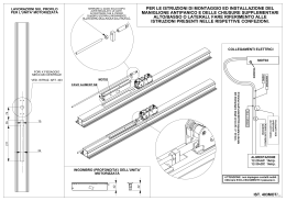
Scheda di posa
Modulo Motorizzato
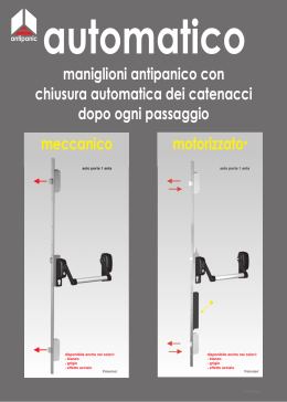
Automatico e motorizzato.cdr
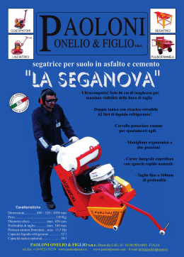
depliant seganova - paolonipesaro.it
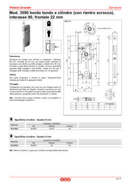
interasse 90, frontale 22 mm
Progetto Sicurezza
A056-I TWIST BSP