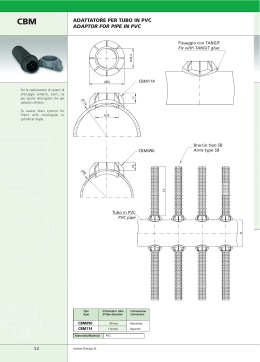
Nozioni di Impiantistica
IMPIANTISTICA • INSTALLATION
Notes concerning the study and the realisation of a system
Nozioni di Impiantistica
IMPIANTISTICA • INSTALLATION
Notes concerning the study and the realisation of a system
NOZIONI DI IMPIANTISTICA
NOTES ON INSTALLATION
La tubazione SISTEM-AIR è composta da PVC antistatico e
autoestin-guente, costruita per garantire il perfetto accoppiamento
tra tubazioni e raccordi.
In particolare le tubazioni sono:
Autoestinguenti, Antistatiche, Calibrate con spessori compresi tra
2,2 mm per la tubazione Ø 50 mm, e 3 mm per i Ø 63/80/100 mm.
Le nostre tubazioni sono di tipo a giunzione ad incollaggio con speciale
colla autosaldante a freddo. Le sue particolari caratteristiche tecniche
garantiscono una perfetta tenuta dei componenti incollati.
La corretta predisposizione e un’installazione della rete tubiera
garantisce il corretto funzionamento dell'impianto e per questo è da
considerarsi senza dubbio la fase più importante per ottenere l'ottimale
funzionamento di un impianto d'aspirapolvere centralizzato.
Si consiglia a tutti gli operatori di osservare scrupolosamente le
indicazioni sottoriportate al fine di semplificare le operazioni della
stesura della rete tubiera ed ottenere un funzionamento ottimale
dell'impianto, mantenendo così inalterate le prestazioni nel tempo.
The SISTEM-AIR piping is made up of antistatic, self-extinguishing
PVC, built to guarantee a perfect combination between piping and
connections.
In particular, the piping is:
Self-extinguishing, Antistatic, Calibrated, with thickness of
between 2.2mm for Ø 50 mm diameter and 3mm for Ø 63/80/100
mm diameter.
All connections of the piping network are glued together with
special self-adhesive cold glue. Its particular technical
characteristics ensure that the glued parts stick perfectly.
The correct setting and installation of the piping network ensures
that the system works properly and this is why it is undoubtedly
considered the most important stage for obtaining optimum
running of the centralised vacuum system.
We advise all operators to stick rigidly to the advice provided in
order to simplify the operations for compiling the piping network
and ensure optimum running of the system, thus keeping a steady
performance over time.
Taglio della tubazione e corretta unione dei raccordi
Cut of the piping and proper joining of connectors
Per ottenere un corretto taglio delle tubazioni utilizzare ESCLUSIVAMENTE l'attrezzo tagliatubi.
In order to cut the pipes properly, use ONLY cylindrical pipe
cutting tool.
La tubazione deve SEMPRE essere posizionata correttamente:
deve sempre combaciare con la battuta del raccordo.
The pipes should ALWAYS be placed correctly: they should
always be inserted till it reaches the ledge.
Taglio CORRETTO e Posizionamento ERRATO
RIGHT cut and WRONG positioning
Attrezzo CORRETTO
Proper equipment
Taglio CORRETTO e Posizionamento CORRETTO
RIGHT cut and RIGHT positioning
Esempi di ERRATO taglio della tubazione
Examples of WRONG pipe cutting
Strumenti di taglio NON idonei.
UNSUITABLE tool for cutting
Esempio di taglio effettuato con strumenti non appropriati.
Example of cut made with an unsuitable tool
Installazione ERRATA
WRONG installation
Attrezzo ERRATO
WRONG equipment
82
www.sistemair.it
rif. 01-2005 ITA/ING
Nozioni di Impiantistica
Incollaggio delle tubazioni ai raccordi
Gluing the piping to the connectors
La fase di incollaggio delle tubazioni ai raccordi è da considerarsi senza
dubbio la fase più delicata dell'impianto d'aspirapolvere centralizzato, in
quanto, se non eseguita correttamente, può generare perdita di carico
all'impianto, causando nel tempo sedimentazione del prodotto aspirato
all'interno delle tubazioni poste sotto traccia. L'operazione corretta consiste
nello spalmare il collante solo sulla tubazione o sulla parte maschio del
raccordo. Questo fa si che all'innesto della tubazione nel raccordo la colla
in eccedenza possa fuoriuscire creando un'ulteriore anello di tenuta. Se
l'operazione fosse svolta al contrario, cioè spalmando il collante sulla
femmina del raccordo all'innesto della tubazione nel raccordo, la colla in
eccedenza cadrebbe all'interno della tubazione.
The stage of gluing the piping to the connectors is without a doubt the
most delicate stage of the central vacuum system because if it is not
carried out properly, there could be a loss in flow of the system. Overtime,
this would cause sedimentation of the vacuumed product inside the piping
located into chase. The operation is carried out properly by spreading the
glue only on the piping or on the male part of the connector. This ensures
that when the piping is fitted to the connector, any excess glue will overflow
creating an extra hold ring. If the operation were to be done the other way
round, that is, spreading the glue onto the female part of the connector,
the excess glue would drip inside the piping when it is fitted to the connector.
Colla
Glue
IMPIANTISTICA • INSTALLATION
Notes concerning the study and the realisation of a system
Installazione CORRETTA
CORRECT Installation
Raggio di curvatura
Radius of the curve
Il raggio di curvatura della rete tubiera posta in esecuzione esterna, o
posta sotto traccia, deve necessariamente essere eseguita con
raccordi di tipo a 45° che garantiranno il minor sforzo possibile di
passaggio dell'aria aspirata, ES: una curva a 90° si può eseguire in
due differenti modi, il primo con un raccordo curvo maschio femmina
ed uno femmina femmina, il secondo con un raccordo curvo femmina
femmina, un pezzetto di tubazione, un altro raccordo curvo femmina
femmina.
Minori saranno i raccordi curvi installati nell'impianto, e maggiore sarà
la velocità dell'aria aspirata, e migliore la resa finale dell'impianto di
aspirapolvere centralizzato.
45°
45°
The radius of the curve of the piping network located externally or into
chase, must be done with 45° connectors that will guarantee as little
force as possible of passing vacuumed air, e.g.: a 90° curve can be
made in two different ways, firstly with a male female and female
female curve connector; secondly with a female female curve
connector, a small piece of pipe and another female female curve
connector.
The fewer curve connectors installed in the system the greater the
speed of the vacuumed air and the better the final performance of the
centralised vacuum system will be.
Installazione CORRETTA
CORRECT Installation
Giunzione lineare della tubazione
Linear junction of the pipe
La giunzione della tubazione deve essere eseguita con l'apposito
raccordo manicotto a doppio battente; il battente presente in tutta la
raccorderia con marchio Sistem-Air è l'elemento che garantisce il
combaciare della tubazione al raccordo. Perchè la tubazione possa
fare perfettamente battuta con i raccordi e non presentare nessun
gradino all'interno delle tubazioni, è INDISPENSABILE eseguire il
taglio con l'apposito attrezzo tagliatubi. Ciò garantirà un taglio preciso,
lineare ed esente da bave.
The junction of the piping must be made with the appropriate double
stop coupling connector; the stop found in all the connectors with a
Sistem-Air label is the element that ensures the piping combines with
the connector. To ensure the piping fits perfecting with the connectors
and there are no gaps inside the piping, it is ESSENTIAL to cut it with
the appropriate tool. This will ensure an exact, linear cut with no burr.
rif. 01-2005 ITA/ING
www.sistemair.it
Battuta interna
Perfect internal fit
Installazione CORRETTA
CORRECT Installation
83
Nozioni di Impiantistica
IMPIANTISTICA • INSTALLATION
Notes concerning the study and the realisation of a system
Senso di aspirazione
Direction of suction
Per la diramazione di più punti presa aspiranti usare i raccordi a derivazione
di tipo a 45° femmina femmina, oppure derivazione a 45° maschio femmina:
questo raccordo viene impiegato sia per la derivazione di un punto presa sullo
stesso piano che per l'esecuzione di colonne montanti in stabili su più livelli. È
fondamentale che la derivazione venga sempre installata correttamente
rispetto al senso di aspirazione dell'impianto (vedi figura). L'errata
installa-zione della derivazione causerà un inevitabile intasamento
dell'impianto.
For the branching of more inlet valve points, use the female female 45° derivation
connectors, or male female 45° derivation. This connector is used both for the
derivation of a socket pipe line on the same floor and for the stable implementation
of upright pipes on several floors. It is essential that the derivation is always
installed correctly in relation to the system’s direction of suction. (see figure)
The incorrect installation of the derivation will inevitably block the system.
Senso di aspirazione
Direction of suction
Alla centrale
to the central
vacuum unit
Installazione CORRETTA
CORRECT Installation
Operazioni particolari
Special operations
Durante le fasi d'installazione vi può capitare di incontrare ostacoli che non si
possono scavalcare a causa della mancanza di livello del sottofondo: questo
problema può essere ovviato con un cosiddetto sottopassaggio.
Il sottopassaggio deve essere eseguito con un raccordo curvo a 45° maschio
femmina; un raccordo a 45° femmina femmina, un pezzetto di tubazione,
un'altra curva a 45° maschio femmina, una curva a 45° femmina femmina.
Questa operazione deve essere eseguita il minor numero possibile di volte
sullo stesso impianto, in quanto creerebbe una grossa forzatura nella velocità
dell'aria aspirata.
During installation you may encounter obstacles that cannot be overcomed
because the foundation is not properly levelled: this problem can be resolved with
a so called underground passage.
The underground passage should be done with a male female 45° curve
connector, a female female 45° connector, a small piece of pipe, another male
female 45°'a1 elbow connector and another female female 45° elbow connector.
This operation should be carried out as few times as possible on the same system,
as it would produce a considerable strain on the speed of the vacuumed air.
Installazione CORRETTA
CORRECT Installation
Giunto di dilatazione
Expansion joint
In condizioni impiantistiche come nel caso della figura sotto riportata, l'attenzione va rivolta alle dilatazioni del terreno: SISTEM-AIR risolve questo problema utilizzando appositi giunti di dilatazione (vedi capitolo "Impiantistica")
da installarsi: uno subito all'uscita delle tubazioni dalla prima struttura, ed un
secondo prima dell'ingresso nella seconda struttura.
La tubazione posta nel terreno dovrà essere coibentata al fine di ridurre al
minimo la condensa all'interno della tubazione, che al contatto con la
polvere aspirata potrebbe creare incrostazioni.
Under system conditions like those shown in the figure below, attention should focus
on expansion of the ground: SISTEM-AIR resolves this problem by using special
expansion joints (see chapter on “Installation”) to be installed: one right at the outlet
of the piping in the first structure and a second one before the inlet of the second
structure. The piping located in the ground should be insulated in order to reduce
condensation inside the piping as much as possible, as this could create incrustation
if it were to come into contact with the dust.
Giunto di dilatazione
Expansion joint
84
www.sistemair.it
rif. 01-2005 ITA/ING
Nozioni di Impiantistica
Contropresa universale a raccordo curvo
Standard mounting plate with elbow connector
Contropresa universale a raccordo diritto
La contropresa universale a raccordo curvo, di soli 7 cm di spessore,
può essere installata in qualsiasi tipo di parete. La contropresa è dotata
di raccordo curvo che ruota su se stesso a 360° al fine di potersi innestare al raccordo in qualsiasi punto esso si trovi.
IMPORTANTE: la contropresa deve sempre essere installata a filo intonaco.
La contropresa universale a raccordo dritto è da considerarsi un
componente adatto per tutte quelle realizzazioni particolari (ristrutturazioni, contropareti, pareti mobili ecc.).
IMPORTANTE: la contropresa deve sempre essere installata a filo intonaco.
Standard mounting plate with straight connector
The standard mounting plate with elbow connector, only 7cm thick, can be
installed in any kind of wall.
The mounting plate is fitted with an elbow connector that rotates at 360°
in order to position itself to the connector, wherever it may be.
IMPORTANT: the mounting plate should always be installed flat into the wall.
The standard mounting plate with straight connector should be
regarded as a suitable part for all those unusual jobs (restoration,
false walls, partitions etc.).
IMPORTANT: the mounting plate should always be installed flat into
the wall.
Installazione CORRETTA
CORRECT Installation
Installazione CORRETTA
CORRECT installation
Fissaggio della contropresa a raccordo curvo
Fitting the mounting plate with elbow connector
Fissaggio della contropresa a raccordo diritto
Fitting the mounting plate with straight connector
L'operazione di fissaggio nella muratura o in esterno della contropresa
a raccordo curvo, richiede la massima precisione per evitare che al
montaggio della presa aspirante, gli elementi di tenuta non aderiscano
perfettamente. Particolare importante è che la scatola della contropresa sia bene a filo intonaco.
L'operazione di fissaggio nella muratura o in esterno della contropresa
a raccordo dritto, richiede la massima precisione per evitare che al
montaggio della presa aspirante, gli elementi di tenuta non aderiscano
perfettamente. Particolare importante è che la scatola della contropresa
sia bene a filo intonaco.
Fitting the mounting plate with elbow connector to the wall or outside
requires maximum precision so that when the inlet valve is fitted, the
holding elements adhere perfectly. It is especially important the
mounting plate box is completely flat into the wall.
Fitting the mounting plate with straight connector to the wall or
outside requires maximum precision so that when the inlet valve is
fitted, the holding elements adhere perfectly. It is especially
important the mounting plate box is completely flat into the wall.
Installazione ERRATA
WRONG installation
Installazione ERRATA
WRONG installation
rif. 01-2005 ITA/ING
IMPIANTISTICA • INSTALLATION
Notes concerning the study and the realisation of a system
www.sistemair.it
85
Nozioni di Impiantistica
IMPIANTISTICA • INSTALLATION
Notes concerning the study and the realisation of a system
Esempio di connessioni base
Example of base connections
O
ALT
RE
NA
CO
SIZIONAE
. PO INTO IR E
NB O PR RI
ZE
A FILN COEZ
NO PP TO RE
N TA AN VE
CO IMPIAPOL TO
ZA
LIZ
IR
SP
D'A NTRA
CE
Esempio di connessioni base per il completamento di un punto presa.
Example of base connection to install the inlet valve.
4
O
ALT
1
RE
NA
CO
SIZIONAE
. PO INTO IR E
NB O PR RI
ZE
A FILN COEZ
NO PP TO RE
N TA AN VE
CO IMPIAPOL TO
IR LIZZA
SP
D'A NTRA
CE
3
1
2
5
1
art.
Descrizione prodotto
Product description
1
1850.0
Tubo PVC Ø 50 mm sp. 2,2
PVC pipe Ø 50 mm, thick 2,2
2
4050.1
Derivazione PVC 45° F.F.F. Ø 50 mm
PVC derivation 45° F.F., Ø 50 mm
3
3050.0
Curva PVC 45° M.F. Ø 50 mm
PVC elbow 45° M.F., Ø 50 mm
4
1450.0
Contropresa universale R.C. c/coperchio Standard mounting plate, straight connector with cover
5
9016.7
Guaina elettrica preinfilata 2x1 25 mt
pre-wired conduit 2x1, 25 mt
5
9016.0
Guaina elettrica preinfilata 2x1 50 mt
pre-wired conduit 2x1, 50 mt
5
9016.1
Guaina elettrica preinfilata 2x1 100 mt
pre-wired conduit 2x1 100 mt
Esempio di collegamento delle prese aspiranti
Example of connection to inlet valves
Contropresa rettangolare a
muro
Rectangular mounting
plate chased in the wall
Morsetti
Clamps
Presa aspirante SISTEM-AIR
SISTEM AIR inlet valve
Placca elettrica (non fornita)
Decorative frame (not provided)
IR
M-A
TE
SIS
CU
86
N
00
09
02
www.sistemair.it
rif. 01-2005 ITA/ING
Nozioni di Impiantistica
Esempio di impianto civile in struttura abitativa su tre livelli
Example of domestic system on three floors
Esempio di impianto dimensionato per l'utilizzo massimo di un solo
operatore per piano (NB: tutti gli impianti della serie civile hanno
una sola contemporaneità di lavoro).
Example of sized system to be used by only one operator at the
most on each floor (NB: all the systems in the domestic range can
only have one operator at a time).
L'impianto in oggetto è realizzato in struttura di tipo civile su tre
diversi livelli, il dimensionamento delle tubazioni aspiranti sarà
esclusivamente di ø 50 mm sia per quanto riguarda la colonna
montante che per quanto riguarda le distribuzioni di piano. Il
posizionamento delle bocchette aspiranti deve tenere conto che la
tubazione flessibile usata per le pulizie sarà di metri 7: è quindi
importante nella fase di posizionamento delle bocchette aspiranti
che si valutino le difficoltà che gli arredi possono creare e non
dimenticare anche di poter raggiungere balconi, terrazzi, ed ogni
altra superficie.
Si raccomanda di eseguire la scelta della centrale aspirante in
base alla metratura della superficie da pulire, al fine di garantire la
massima durata e le migliori prestazioni nel tempo.
The system in question is created in a domestic structure on three
floors. The piping will be exclusively ø 50 mm both as regards the
upright pipe and the distribution on each floor. The position of the
vacuum openings should take into consideration the fact that the
hose used for cleaning is 7 metres: it is therefore important when
positioning the vacuum openings to consider the problems that
furniture might cause and not forget to add balconies, terraces
and other surface areas.
The central vacuum units should be selected according to the
surface area to be cleaned, in order to ensure long life and the
best performance over time.
IMPIANTISTICA • INSTALLATION
Notes concerning the study and the realisation of a system
STUDIO
STUDY
CAMERA
ROOM
A
A
BAGNO
BATHROOM
SOGGIORNO
LIVING ROOM
A
BAGNO
BATHROOM
WC
WC
CAMERA
ROOM
SPOGLIATOIO
CHANGING ROOM
A
A
A
CAMERA
ROOM
CUCINA
KITCHEN
PIANTA PIANO PRIMO
PLAN OF FIRST FLOOR
PIANTA PIANO TERRENO
PLAN OF GROUND FLOOR
MAGAZZINO
STOCK ROOM
GARAGE
GARAGE
A
IMPIANTI
SYSTEMS
LEGENDA
DESCRIPTION
MAGAZZINO
STOCK ROOM
A
Tubazione in PVC ø 50 mm
Ø 50 mm PVC pipe network
LAVANDERIA
LAUNDRY
A
Linea Microinterruttore
Micro switch line
A
A
RIMESSA
STOREROOM
A
A
CENTRALE TERMICA
CENTRAL HEATING AREA
Colonna Montante
Vertical pipe
SERRA
WINTER
GARDEN
PIANTA PIANO INTERRATO
PLAN OF BASEMENT FLOOR
rif. 01-2005 ITA/ING
Punto Presa Aspirante
Inlet valve
www.sistemair.it
Centrale aspirante
Central vacuum unit
87
IMPIANTISTICA • INSTALLATION
Impiantistica
IMPIANTISTICA
INSTALLATION
Ambito di installazione:
Installation area:
Il materiale impiantistico SISTEM-AIR in materiale PVC è adatto a
tutte le installazioni di impianti di aspirazione centralizzata e si
può dividere in 4 categorie di prodotto:
- Tubazione di colore grigio Ø 50 mm con spessore 2,2 mm,
Ø 63 - Ø 80 - Ø 100 con spessore 3 mm
- Raccordi di colore grigio Ø 50 mm con spessore 2,2 mm,
Ø 63 - Ø 80 - Ø 100 con spessore 3 mm
- Guaina elettrica di colore grigio con inseriti N. 2 conduttori da 1 mm2
- Collante speciale autosaldante per la giunzione delle tubazioni
ai raccordi
The SISTEM-AIR installation material in PVC is suitable for all kinds
of central vacuum systems and can be divided into four product
categories:
- Grey Ø 50 mm, 2.2 mm thick . Ø 63 - Ø 80 - Ø 100mm, 3.0 mm
thick piping
- Grey Ø 50 mm, 2.2 mm thick. Ø 63 - Ø 80 - Ø 100mm, 3.0 mm
thick connectors
- Grey conduit with 2, 1mm2 conductors inserted.
- Special self-adhesive glue to join the piping to the connectors.
IMPIANTISTICA • INSTALLATION
Installation
Particular characteristics of the product:
Particolarità distintive di prodotto:
Prodotti di impiantistica di qualità e robustezza, rispondenti alle più
severe omologazioni e certificazioni di qualità e sicurezza, atta a
soddisfare le più esigenti richieste impiantistiche.
- Tubazione in PVC ridotta al minimo carico statico.
- Tubazione di colore grigio a normativa Uni.
- Tubazione di tipo rigido, con raccordi ad ampio raggio di curvatura.
- Raccordi con tacche di riferimento angolare per un corretto
accoppiamento tra tubazioni e raccordi.
- Materiale plastico PVC saldabile a freddo con incollatura tramite
collante speciale.
- Materiale in PVC resistente al fuoco secondo la classe di resistenza
M1 e norme CEI.
- Guaina elettrica preinfilata grigia Ø 16 mm dotata di marcatura CE,
IMQ, adatta ad ambienti ordinari e particolari, dove sia necessario
l’uso di un prodotto atossico.
- Certificazione Istituto Italiano dei Plastici per rispondenza alle norme UNI.
Quality, sturdy system products that meet with the strictest safety
and quality homologations and certifications that satisfy even the
most difficult system requirements.
- PVC piping with static load reduced to a minimum.
- UNI approved grey piping.
- Rigid piping with connectors that have a wide radius of curving.
- Connectors with angular reference notches for a correct coupling
between piping and connectors.
- PVC plastic material that can be welded cold using a special glue.
- Fire resistant PVC material in compliance with M1 resistance cat.
and IEC regulations.
- Grey Ø 16 mm pre-wired conduit with CE, IMQ labelling, suitable
for ordinary and unusual environments where you need to use non
toxic products.
- Certification from the Italian Institute of Plastics in compliance with
UNI regulations.
Main characteristics:
Caratteristiche:
Tubazione di tipo rigido con raccordi ad ampio raggio di curvatura
Materiale plastico PVC saldabile a freddo con incollatura a mezzo
collante speciale
Certificazione Istituto Italiano dei Plastici (I.I.P. num. 261) per
rispondenza alle norme UNI
Rispondenza alla resistenza al fuoco secondo norma CEI 23-29
Criteri di scelta della rete tubiera:
La tubazione e i raccordi in PVC sono idonei a tutti i tipi di installazione di impianti di aspirazione centralizzata.
Dove esistono particolari problemi di resistenza meccanica o si
installano tubi a vista fuori traccia si possono utilizzare tubi di
alluminio.
Rigid piping with connectors that have a wide radius of curving.
PVC plastic material that can be welded cold using a special glue.
Certification from the Italian Institute of Plastics in compliance with
UNI regulations.
Fire resistant PVC material in compliance with CEI 23-29 regulations.
Criteria for choosing the piping network:
The PVC piping and connectors are suitable for all kinds of centralised
vacuum system installations.
Aluminium piping can be used where there are particular mechanical
resistance problems, or, when installing visible piping.
Technical note
Nota tecnica
When it is necessary to cross an external section with a rigid pipeline
it is opportune to prepare a suitable isolation with the addition of
expansion joints (art. 5050.0)
Quando si renda necessario l'attraversamento di un tratto esterno
con la tubazione rigida è opportuno disporre un adeguato isolmento
dello stesso con l'aggiunta di giunti di dilatazione (art. 5050.0).
Any other material would jeopardise the system’s warranty and could
create blocking in the piping network.
Avvertenza
Warning
Il materiale impiantistico tipo tubo e raccordi sono espressamente
concepiti e realizzati per l'aspirazione centralizzata.
Utilizzare il materiale impiantistico dedicato realizza impianti con
massima garanzia di prestazione e sicurezza di non intasamento.
Materiali diversi pregiudicano la garanzia di impianto e possono
creare intasamenti alla rete tubiera.
The installation material, such as pipes and connectors, has been
specifically designed and created for central vacuuming.
Using the specific installation material allows you to create systems
with a maximum guarantee on performance and the assurance that
it will not block.
rif. 01-2005 ITA/ING
www.sistemair.it
89
Materiale impiantistico
IMPIANTISTICA • INSTALLATION
Installation material
MATERIALE IMPIANTISTICO
INSTALLATION MATERIAL
Tubazione rigida e raccordi in PVC costruiti appositamente per impianti
di aspirapolvere centralizzati, al fine di creare un perfetto accoppiamento
fra tubazione e raccordi; i raccordi sono forniti solo a 45° per permettere
il miglior fluire dell’aria senza creare la possibilità di intasamento
dell’impianto.
Rigid PVC piping and connectors especially designed for central
vacuum systems with a view to create a perfect fit between the piping
and connectors; only 45° connectors are provided to allow for the
best air flow possible without creating the possibility of the system
blocking.
NB: E’ importantissimo che la tubazione in PVC rigido venga
tagliata utilizzando l’apposito strumento (tagliatubi) e che venga
garantita la tenuta fra le giunzioni utilizzando il collante speciale
SISTEM-AIR in abbondante quantità, spalmato sul maschio e
mai sulla femmina del raccordo.
N.B.: it is extremely important that the rigid PVC piping is cut
using the appropriate tool (pipe cutter) and that the hold between
the joints is guaranteed by using the special SISTEM AIR glue
in abundance, spreading it on the male and never on the female
connector.
Tubazione in PVC
PVC piping
IMBALLO m
PACKING m
ARTICOLO
ARTICLE
DESCRIZIONE
DESCRIPTION
1850.0
TUBO PVC ø 50 spessore mm 2,2 (barre da m 2,5)
PVC PIPE (2.5 m bars) ¿ 50, thick 2.2 mm
25
1863.0
TUBO PVC ø 63 spessore mm 3 (barre da m 2,5)
PVC PIPE (2.5 m bars) ¿ 63, thick 3 mm
25
1880.0
TUBO PVC ø 80 spessore mm 3 (barre da m 2,5)
PVC PIPE (2.5 m bars) ¿ 80, thick 3 mm
10
1810.0
TUBO PVC ø 100 spessore mm 3 (barre da m 2,5)
PVC PIPE (2.5 m bars) ¿ 100, thick 3 mm
10
Tubazione in alluminio
Aluminium piping
IMBALLO m
PACKING m
ARTICOLO
ARTICLE
DESCRIZIONE
DESCRIPTION
1850.0A
TUBO ALLUMINIO LEGA 6060 ø 50 (m 3)
ALUMINIUM ALLOY PIPE ¿ 50 (3 m bars)
9
1863.0A
TUBO ALLUMINIO LEGA 6060 ø 63 (m 3)
ALUMINIUM ALLOY PIPE ¿ 63 (3 m bars)
9
Curve 45° in pvc
45° elbow in PVC
90
IMBALLO pz.
PACKING pc.
ARTICOLO
ARTICLE
DESCRIZIONE
DESCRIPTION
3050.0
CURVA PVC 45° maschio/femmina ø 50
PVC elbow 45° male/female ¿ 50 mm
60
3063.0
CURVA PVC 45° maschio/femmina ø 63
PVC elbow 45° male/female ¿ 63 mm
30
3080.0
CURVA PVC 45° maschio/femmina ø 80
PVC elbow 45° male/female ¿ 80 mm
1
3010.0
CURVA PVC 45° maschio/femmina ø 100
PVC elbow 45° male/female ¿ 100 mm
1
3050.1
CURVA PVC 45° femmina/femmina ø 50
PVC elbow 45° male/female ¿ 50 mm
60
3063.1
CURVA PVC 45° femmina/femmina ø 63
PVC elbow 45° male/female ¿ 63 mm
30
3080.1
CURVA PVC 45° femmina/femmina ø 80
PVC elbow 45° male/female ¿ 80 mm
1
3010.1
CURVA PVC 45° femmina/femmina ø 100
PVC elbow 45° male/female ¿ 100 mm
1
www.sistemair.it
rif. 01-2005 ITA/ING
Materiale impiantistico
MATERIALE IMPIANTISTICO
INSTALLATION MATERIAL
Derivazione 45° in PVC
45° derivation in PVC
IMBALLO pz.
PACKING pc.
ARTICOLO
ARTICLE
DESCRIZIONE
DESCRIPTION
4050.0
DERIVAZIONE PVC 45° maschio/femmina/femmina ø 50
PVC DERIVATION 45° male/female/female ¿ 50
20
4063.0
DERIVAZIONE PVC 45° maschio/femmina/femmina ø 63
PVC DERIVATION 45° male/female/female ¿ 63
15
4080.0
DERIVAZIONE PVC 45° maschio/femmina/femmina ø 80
PVC DERIVATION 45° male/female/female ¿ 80
1
4010.0
DERIVAZIONE PVC 45° maschio/femmina/femmina ø 100
PVC DERIVATION 45° male/female/female ¿ 100
1
4050.1
DERIVAZIONE PVC 45° femmina/femmina/femmina ø 50
PVC DERIVATION 45° male/female/female ¿ 50
20
4063.1
DERIVAZIONE PVC 45° femmina/femmina/femmina ø 63
PVC DERIVATION 45° male/female/female ¿ 63
15
4080.1
DERIVAZIONE PVC 45° femmina/femmina/femmina ø 80
PVC DERIVATION 45° male/female/female ¿ 80
1
4010.1
DERIVAZIONE PVC 45° femmina/femmina/femmina ø 100
PVC DERIVATION 45° male/female/female ¿ 100
1
IMPIANTISTICA • INSTALLATION
Installation material
Manicotti in PVC per giunzioni lineari
PVC coupling for linear junctions
IMBALLO pz.
PACKING pc.
ARTICOLO
ARTICLE
DESCRIZIONE
DESCRIPTION
1150.1
MANICOTTO PVC CON BATTENTE ø 50
¿ 50 PVC STOP COUPLING
100
1163.1
MANICOTTO PVC CON BATTENTE ø 63
¿ 63 PVC STOP COUPLING
40
1180.1
MANICOTTO PVC CON BATTENTE ø 80
¿ 80 PVC STOP COUPLING
1
1110.1
MANICOTTO PVC CON BATTENTE ø 100
¿ 100 PVC STOP COUPLING
1
Aumenti eccentrici in PVC
PVC pipe adapter
IMBALLO pz.
PACKING pc.
ARTICOLO
ARTICLE
DESCRIZIONE
DESCRIPTION
6063.3
AUMENTO ECCENTRICO ø 50/63
ADAPTOR ¿ 50/63
1
8080.3
AUMENTO ECCENTRICO ø 63/80
ADAPTOR ¿ 63/80
1
1010.3
AUMENTO ECCENTRICO ø 80/100
ADAPTOR ¿ 80/100
1
Giunti di dilatazione in PVC
PVC expansion joints
IMBALLO pz.
PACKING pc.
ARTICOLO
ARTICLE
DESCRIZIONE
DESCRIPTION
5050.0
GIUNTO DI DILATAZIONE ø 50
¿ 50 EXPANSION JOINT
1
5050.2
GIUNTO DI DILATAZIONE ø 63
¿ 63 EXPANSION JOINT
1
rif. 01-2005 ITA/ING
www.sistemair.it
91
Materiale impiantistico
IMPIANTISTICA • INSTALLATION
Installation material
MATERIALE IMPIANTISTICO
INSTALLATION MATERIAL
Tappi a vite in PVC per ispezioni
PVC screw caps for inspecting
IMBALLO pz.
PACKING pc.
ARTICOLO
ARTICLE
DESCRIZIONE
DESCRIPTION
5050.1
TAPPO A VITE PER ISPEZIONE ø 50
¿ 50 PVC INSPECTION SCREW CAP
1
6063.1
TAPPO A VITE PER ISPEZIONE ø 63
¿ 63 PVC INSPECTION SCREW CAP
1
8080.1
TAPPO A VITE PER ISPEZIONE ø 80
¿ 80 PVC INSPECTION SCREW CAP
1
1010.1
TAPPO A VITE PER ISPEZIONE ø 100
¿ 100 PVC INSPECTION SCREW CAP
1
Griglia di sfiato aria
Air vent grate
IMBALLO pz.
PACKING pc.
ARTICOLO
ARTICLE
DESCRIZIONE
DESCRIPTION
5050.4
GRIGLIA DI SFIATO ø 50
¿ 50 EXHAUST VENT
1
5063.4
GRIGLIA DI SFIATO ø 63
¿ 63 EXHAUST VENT
1
Silenziatore di sfiato aria
Air vent silencer
IMBALLO pz.
PACKING pc.
ARTICOLO
ARTICLE
DESCRIZIONE
DESCRIPTION
110001
SILENZIATORE DI SFIATO UNIVERSALE IN PVC ø 50 / 2”
STANDARD PVC SILENCER ¿ 50 / 2
1
Collante speciale per tubazioni in PVC
Special glue for PVC piping
IMBALLO pz.
PACKING pc.
ARTICOLO
ARTICLE
DESCRIZIONE
DESCRIPTION
9225.1
COLLA SPECIALE g 250 con pennello
250g of SPECIAL GLUE with brush
5
9225.2
COLLA SPECIALE g 500 con pennello
500g of SPECIAL GLUE with brush
5
9500.0
COLLA SPECIALE g 500 senza pennello
500g of SPECIAL GLUE without brush
4
Guaina elettrica preinfilata da 2x1 mm2
pre-wired conduit 2x1 mm2
92
IMBALLO pz.
PACKING pc.
ARTICOLO
ARTICLE
DESCRIZIONE
DESCRIPTION
9016.7
GUAINA ELETTRICA PREINFILATA mm2 2x1 (25 m)
PRE-WIRED CONDUIT 2x1 mm2 (25m)
1
9016.0
GUAINA ELETTRICA PREINFILATA mm2 2x1 (50 m)
PRE-WIRED CONDUIT 2x1 mm2 (50m)
1
9016.1
GUAINA ELETTRICA PREINFILATA mm2 2x1 (100 m)
PRE-WIRED CONDUIT 2x1 mm2 (100m)
1
www.sistemair.it
rif. 01-2005 ITA/ING
Materiale impiantistico
MATERIALE IMPIANTISTICO
INSTALLATION MATERIAL
Valvole a sfera di sezionamento manuale
Ball valves for manual division
IMBALLO pz.
PACKING pc.
ARTICOLO
ARTICLE
DESCRIZIONE
DESCRIPTION
2050.0
VALVOLA A SFERA DI SEZIONAMENTO MANUALE ø 50
BALL VALVES FOR MANUAL DIVISION ¿ 50
1
2050.1
VALVOLA A SFERA DI SEZIONAMENTO MANUALE ø 63
BALL VALVES FOR MANUAL DIVISION ¿ 63
1
2050.2
VALVOLA A SFERA DI SEZIONAMENTO MANUALE ø 80
BALL VALVES FOR MANUAL DIVISION ¿ 80
1
2050.3
VALVOLA A SFERA DI SEZIONAMENTO MANUALE ø 100
BALL VALVES FOR MANUAL DIVISION ¿ 100
1
IMPIANTISTICA • INSTALLATION
Installation material
Manicotti tagliafuoco
Fire stop coupling
IMBALLO pz.
PACKING pc.
ARTICOLO
ARTICLE
DESCRIZIONE
DESCRIPTION
1150.3
MANICOTTO TAGLIAFUOCO ø 50
FIRE STOP COUPLING ¿ 50
1
1163.2
MANICOTTO TAGLIAFUOCO ø 63
FIRE STOP COUPLING ¿ 63
1
1180.2
MANICOTTO TAGLIAFUOCO ø 80
FIRE STOP COUPLING ¿ 80
1
Tappo prova impianti
Screw cap for testing installation
IMBALLO m
PACKING pc.
ARTICOLO
ARTICLE
DESCRIZIONE
DESCRIPTION
5050.5
TAPPO PROVA IMPIANTI SERIE CIVILE
SCREW CAP FOR TESTING DOMESTIC SYSTEM INSTALLATIONS
rif. 01-2005 ITA/ING
www.sistemair.it
5
93
Impiantistica
IMPIANTISTICA • INSTALLATION
Installation
CARATTERISTICHE TECNICHE MATERIALE IMPIANTISTICO
TECHNICAL CHARACTERISTICS OF THE INSTALLATION MATERIAL
TUBAZIONI
PIPING
Ø 50 x 2.2 mm, Ø 63 x 3 mm, Ø 80 x 3 mm, Ø 100 x 3 mm.
Tubazioni in PVC (cloruro di polivinile non plastificato, PVC-U) per
aspirazione di aria.
Tubazioni autoestinguenti, di classe 1 secondo classificazione materiali
del D.M.26.06.1984 in base a metodi di prova ISO 1182, UNI 8457.
Colore grigio.
Conformità alle normative:
Tubi Ø 50 – Capitolato basato su ex UNI 7443:1985 + F.A. 178:1987
Certificazione P.I.I.P. rilasciata dall’istituto Italiano dei Plastici.
Tubi Ø 63-80-100 – UNI EN 1329:2000
Certificazione I.I.P. rilasciata dall’istituto Italiano dei Plastici.
Marchio di conformità applicato: Piip/c 261.
Le tubazioni rigide a sezione circolare SISTEM-AIR sono destinate
all’utilizzo di impianti di aspirazione centralizzata e allo scarico non
in pressione o a ventilazione compressa.
Idonee per giunti ad incollaggio.
Ø 50x2.2 mm, Ø 63x3 mm, Ø 80 x3 mm, Ø 100x3 mm.
PVC piping (non plastic polyvinyl chloride, PVC-U) for air suction.
Self-extinguishing piping, cat. 1 according to material classification
in the D.M 26.06.1984 (Ministerial Degree) based on ISO 1182, UNI
8457 test methods.
Grey colour
Compliance with legislation:
Ø 50 pipes – Specification based on former UNI 7443:1985 + F.A.
178:1987
P.I.I.P. certification issued by the Italian Institute of Plastics.
Ø 63-80-100 pipes - UNI EN 1329:2000
P.I.I.P. certification issued by the Italian Institute of Plastics.
Applied compliance label: Piip/c 261.
The SISTEM AIR rigid piping with circular section is for use on
centralised vacuum systems and for discharge that is not under
pressure or compressed ventilation.
Ideal for glued joints.
RACCORDI
CONNECTORS
Raccorderia in PVC, per aspirazione di aria.
I raccordi sono a diametro di accoppiamento calibrato, per ottenere
la massima precisione di accoppiamento con le tubazioni.
Disponibile in molteplici forme ed innesti, nei diametri Ø 50 , Ø 63 ,
Ø 80 , Ø 100, oltre ai molteplici accessori.
Colore: grigio.
Autoestinguente.
Grado di resistenza al fuoco: classe di comportamento secondo le
norme RSN - M1 (qualità di standard superiore nel campo di resistenza
al fuoco da parte di materiale plastico)
PVC connectors for air suction.
The connectors have a calibrated coupling diameter to obtain the
best coupling with the piping.
Available in numerous forms and connections, in Ø 50 , Ø 63 , Ø 80,
Ø 100 diameters as well as the numerous accessories.
Colour: grey.
Self-extinguishing.
Fire resistance level: behavioural category according to RSN-M1
legislation (superior standard quality in the field of plastic fire resistance)
GUAINA ELETTRICA PREINFILATA
PRE-WIRED CONDUIT
Guaina elettrica isolante,protettiva, pieghevole preinfilata.
Diametro Ø 16 mm, colore grigio.
Marcatura CE , IMQ.
Certificazione IMQ.
Conforme alle seguenti normative:
-EN 50086-1:1993
-EN 50086-2-2:1995 + A11:1998
Prodotti conformi ai requisiti essenziali della direttiva B.T. 73/23/CEE
e successive modifiche.
Tubo con classificazione base Cl.3422, corrugato, NON propagante
la fiamma.
Ulteriore classificazione Cl.32-0-010.
Prodotto esente da alogeni in conformità alle norme:
CEI EN 50267-2-1:1999 e CEI EN 50267-2-2:1999.
Questo tipo di guaine è adatto per tutti quei luoghi dove siano richieste
le caratteristiche di atossicità e non emissioni di fumi o gas tossici.
Documenti di riferimento:
CEI EN 50267-1:1999 – Class. CEI 20-37/2-0 – F.5325
CEI EN 50267-2-1:1999 – Class. CEI 20-37/2-1 – F.5326
Equivalente a IEC 60754-1
CEI EN 50267-2-2:1999 – Class. CEI 20-37/2-2 – F.5327
Equivalente a IEC 60754-2.
Idonei per i casi in cui siano richieste particolari resistenze meccaniche
agli urti:
Resistenza allo schiacciamento (tubo): Classe 3 medio (superiore a
750 N su 5 cm a +20°C)
Resistenza all’urto (tubo): Classe 3 medio (2 joule a –5°C)
Temperatura minima d’esercizio (tubo): Classe 2 (-5°C)
Temperatura massima di esercizio (tubo): Classe 1 (+60°C)
Per i cavi:
I fili conduttori sono certificati IMQ, di colore rosso, tipo No7VK, non
propagante l’incendio, con sezione 1mm2,
Normative:
CEI 20-20, 20-22, 20-37
CEI-UNEL 35752
CENELEC HD 21
94
Pre-wired, protective, folding insulating conduit.
Grey with Ø 16 mm diameter.
CE, IMQ labelling.
IMQ certification.
Complies with the following regulations:
-EN 50086-1:1993
-EN 50086-2-2:1995 +A11:1998
Products conform to the essential requirements found in the B.T.
73/23/CEE directive and later changes.
Pipe with C1 base classification. 3422, corrugated, DOES NOT
propagate flames.
Further classification C1.32-0-010.
Product has no halogen as required by law:
IEC EN 50267-2-1:1999 and IEC EN 50267-2-2:1999.
This kind of conduit is suitable for all those places requiring non toxic
characteristics and non emission of fumes or toxic gases.
Reference document:
IEC EN 50267-1:1999 -Cat. IEC 20-37/2-0- F. 5325
IEC EN 50267-2-1:1999-Cat. IEC 20-37/2-1- F. 5326
The same as IEC 60754-1
IEC EN 50267-2-2:1999-Cat. IEC 20-37/2-2- F. 5327
The same as IEC 60754-2.
Suitable in cases where particular mechanical resistance is needed.
Crush resistance (pipe): Cat. 3 average (greater than 750 N on 5 cm
at +20°C)
Blow resistance (pipe): Cat. 3 average (2 joules at -5°C)
Minimum working temperature (pipe): Cat. 2 (-5°C)
Maximum working temperature (pipe): Cat. 1 (+60°C)
For the cables:
The conduction wires are IMQ certified, red and No7VK type, do not
propagate fire, with 1 mm2 section
Legislation:
IEC 20-20, 20-22, 20-37
IEC-UNEL 35752
CENELEC H D 21
www.sistemair.it
rif. 01-2005 ITA/ING
Impiantistica
MANICOTTI TAGLIAFUOCO
FIRE FIGHTING COUPLINGS
Da applicare in tutti quei casi in cui i locali sono sottoposti a
normative antincendio.
Classe di resistenza al fuoco: REI 180 certificata (180 min).
I manicotti tagliafuoco sono impiegati per sigillare gli attraversamenti
di tubi in tecnopolimero (PVC, PE, PP,..) in compartimentazioni antincendio.
A temperatura di circa 150°C il materiale interno intumescente inizia
ad espandersi aumentando il proprio volume di circa 10 volte, sviluppando una notevole pressione sufficiente ad attivare il sistema di
chiusura resistente al fuoco che garantisce la tenuta dei gas combusti.
Leggere attentamente le schede di sicurezza prodotti prima dell’utilizzo.
Per il loro utilizzo i manicotti tagliafuoco devono essere usati in conformità dei certificati di resistenza al fuoco sia come numero, sia
come orientazione e sia come sistema di fissaggio.
To be applied everywhere that fire prevention legislation
is in effect.
Fire resistance cat.: REI 180 certified (180 min).
The fire fighting couplings are used to seal the crossings of engineering
resin pipes (PVC, PE, PP,..) in fire prevention compartments.
At a temperature of approx. 150°C, the internal intumescent material
starts to expand thus increasing its own volume by about 10 times,
developing a considerable pressure, enough to activate the fire
resistance closure system that keeps in burning gases.
Read the safety instructions before use.
To use them, the fire stop couplings must be used in compliance
with fire resistance certificates both in number and orientation as well
as fixing system.
IMPIANTISTICA • INSTALLATION
Installation
COLLANTI
GLUE
Collanti adesivi certificati a base di PVC disciolto in solvente.
Componenti di base: resine in PVC.
Componenti speciali: solventi organici.
Effettua un saldatura della giunzione incollata.
Gli incollaggi effettuati possiedono la stessa resistenza agli agenti
chimici e le stesse proprietà meccaniche del PVC rigido.
La sua viscosità controllata permette una facile applicazione senza
colature.
Ideale per giunzioni longitudinali di tubi in PVC rigido, assemblaggi
di tubi e raccordi in PVC.
rif. 01-2005 ITA/ING
Certified PVC based glue dissolved in solvent.
Basic ingredients: PVC resins.
Special ingredients: organic solvents.
Solder the glued junction.
Gluing is equally resistant to chemical agents and has the same
mechanical properties as hard PVC.
Its controlled viscosity means it can easily be applied without gluing.
Ideal for longitudinal junctions on hard PVC pipes and the assembling
of PVC pipes and connectors.
www.sistemair.it
95
Kit impiantistici
IMPIANTISTICA • INSTALLATION
Installation kit
KIT IMPIANTISTICI
INSTALLATION KIT
Il kit impiantistico comprende tutto il necessario per la realizzazione
della predisposizione di un impianto di aspirazione centralizzata. I kit
impiantistici sono fra loro abbinabili al fine di ottenere la quantità di
punti presa che si desiderano installare. (Esempio: un impianto da 8
punti presa può essere realizzato sommando n.1 kit a 3 punti presa +
1 kit a 5 punti presa; in alternativa possono essere utilizzati n. 2 kit a 4
punti presa).
La lista del materiale contenuto nel kit può essere verificato nelle
tabelle di seguito riportate.
N.B. Il kit impiantistico è realizzato con il fine di semplificare al
massimo l'acquisto del materiale per predisposizione impianto.
Per impianti su edifici a pianta regolare, è infatti possibile
avere a disposizione tutto il materiale con la certezza di poter
portare a termine la rete tubiera senza ulteriori aggiunte di
materiale impiantistico.
Avvertenza
Nei kit impiantisitici è compreso il solo materiale d'installazione, le
prese aspiranti fanno parte del completamento dell'impianto e
sono quindi da scegliere a parte nella apposita sezione catalogo.
96
The installation kit includes everything needed to fit a central vacuum
system. The installation kits can be combined to obtain the number
of sockets you wish to install.
(e.g.: an 8 inlets system can be created by combining 1 kit with 3 inlets
+ 1 kit with 5 inlets; alternatively, 2 kits with 4 inlets can be used).
The list of material contained in the kit can be checked in the tables
below.
N.B. the installation kit is made with a view to simplifying the
purchase of material for fitting the system, as much as possible.
For systems in buildings with standard layout, it is possible to
have all the material available with the certainty of being able to
complete the piping network without further additional installation
material.
Warning
Only the installation material is included in the kit because the inlet
valves are part of the system and should therefore be selected from
the right section of the catalogue.
www.sistemair.it
rif. 01-2005 ITA/ING
Kit impiantistici
Kit impiantistici con controprese rettangolari (articolo 1450.0)
Installation kit with rectangular mounting plates (parts no. 1450.0)
Art./Art.
1450.0
Art./Art.
1850.0
Art./Art.
3050.0
Art./Art.
3050.1
Art./Art.
4050.1
Art./Art.
1150.1
ARTICOLO Punti presa Contropresa Tubo PVC
N°
m
ARTICLE
RC Pz.
No. of inlets Elbow connecto PVC pipe
(m)
(Pieces)
Curva MF
Pz.
Elbow MF
(pieces)
Curva FF
Pz.
Elbow FF
(pieces)
Derivazione
FF Pz.
Derivation FF
(pieces)
Manicotto
Pz.
Coupling
(pieces)
Art./Art.
5050.4
Art./Art.
9225.1
TO
AL
Griglia sfiato Guaina elettrica Colla speciale
Pz.
m
Pz.
Vent grate
Conduit Special glue
(pieces)
(m)
(pieces)
7030.3
3
3
20
9
12
2
9
1
25
1
7030.4
4
4
28
12
16
3
12
1
37,5
1
7030.5
5
5
36
15
20
4
15
1
50
1
IMPIANTISTICA • INSTALLATION
Installation kit
Kit impiantistici con controprese quadrate (articolo 1450.4B)
Installation kit with square mounting plates (parts no. 1450.4B)
Art./Art.
1450.4B
Art./Art.
1850.0
Art./Art.
3050.0
Art./Art.
3050.1
Art./Art.
4050.1
Art./Art.
1150.1
ARTICOLO Punti presa Contropresa Tubo PVC
N°
m
ARTICLE
RC Pz.
No. of
Elbow connecto PVC pipe
sockets
(m)
(Pieces)
Curva MF
Pz.
Elbow MF
(pieces)
Curva FF
Pz.
Elbow FF
(pieces)
Derivazione
FF Pz.
Derivation FF
(pieces)
Manicotto
Pz.
Coupling
(pieces)
Art./Art.
5050.4
Art./Art.
9225.1
Griglia sfiato Guaina elettrica Colla speciale
Pz.
m
Pz.
Vent grate
Conduit
Special glue
(pieces)
(m)
(pieces)
7030.3E
3
3
20
9
12
2
9
1
25
1
7030.4E
4
4
28
12
16
3
12
1
37,5
1
7030.5E
5
5
36
15
20
4
15
1
50
1
rif. 01-2005 ITA/ING
www.sistemair.it
97
CONTROPRESE E PRESE ASP. • MOUNTING PLATES ND INLET VALVES
Scarica