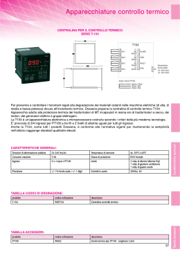
HPUG : UNITÀ DI CONTROLLO MOTORE AD ALTE PRESTAZIONI PER MOTORI A 2 E 4 TEMPI
La HPUG e' una centralina di Controllo Motore derivata dalla ECUG e dedicata alla gestione di motori anche complessi a 2 e 4 Tempi ad
Iniezione Elettronica. La HPUG può controllare motori fino a 2 Cilindri. In alcune condizioni e' anche possibile gestire motori fino ad 4
cilindri. Data la grande flessibilità della HPUG le diverse configurazioni applicative sono proposte attraverso diversi Firmware applicativi,
configurazioni Hardware e diverse configurazioni di pinout.
•
HPUG Hardware e K1RACExx Firmware sono dedicati alla gestione di
applicazioni Auto.
•
HPUG Hardware e K2RACExx Firmware sono dedicati alla gestione di
applicazioni Moto.
Su tutti i dispositivi della famiglia HPUG l'accesso alle Variabili, Tabelle e Piani di calibrazione e' possibile con i diritti Basic del software
Maya senza l'utilizzo di Licenze avanzate. I dispositivi della famiglia HPUG vengono forniti senza mappa. File di mappa a titolo
esemplificativo sono distribuiti se disponibili.
Scheda Tecnica HPUG rev.01 © 2010 by Athena Evolution
Electrical and CPU Data
Power:
•
•
•
•
Nominal supply voltage 13,5 V
Supply voltage range 6 to 18 V
M ax Current Sink without Loads <200
<200 mA
CPU 32 Bit RISC 50 MHz
Inputs:
•
•
•
•
•
•
1 Input for Inductive Crankshaft Sensor (Trigger
(Trigger Wheel)
1 HallHall- effect Camshaft Sensor
2 HallHall-effect Wheel Speed Sensors
Internal Barometric Pressure Sensor
3 Digital Inputs :
o
Tipover
o
Sidestand
o
Map Change
6 Analog Inputs :
o
TPS1
o
TPS2
o
MAP
o
LAMBDA
o
AIR TEMPERATURE
o
ENGINE TEMPERATURE
Scheda Tecnica HPUG rev.01 © 2010 by Athena Evolution
Output:
Output:
•
•
•
•
•
•
•
•
2 Low Side Injector Power Stage
2 IGBT Ignition Coil Power Stage
2 Low Side Power Stage for Direct control of Cooling Fan and Fuel Pump
1 Low Side Power Stage for Custom Function
1 HH-Bridge 5A for EXUP
EXUP control
1 Stepper Motor Driver
6 Low Side protected Power Stages :
o
ECR Relay Driver
o
Light Relay Driver [1]
o
Tachometer
o
MIL Lamp
o
Solenoid 1
o
Solenoid 2
1 Protected Sensors Supply Voltage (5V )
Communications Interfaces:
Interfaces:
•
1 RS232
System Layout
•
•
•
•
Trigger Wheels : NN- 2, NN-2 with CAM Reference, NN- 2 on Camshaft,NCamshaft,N- 1, NN -1 with
with CAM Reference, NN -1 on Camshaft, Renix
alpha/n and/or MAP compensated
Load indicated by Throttle Position (“TPS
( TPS”)
TPS ) and/or MAP
Cam sensor elimination with sequential injection and ignition (depend on the engine layout)
Standard Functions [*]
•
Ignition and Injection timing configurable parameters over 32 x 16 calibration setpoints
(1 or 2) Main fuel injection time
o
o
(1) Fuel correction per cylinder
o
(1or 2) EndEnd -ofof-Injection timing
o
(1 or 2) Main ignition timing
o
(1) Ignition timing correction per cylinder
Scheda Tecnica HPUG rev.01 © 2010 by Athena Evolution
•
•
•
•
•
•
•
•
•
•
Compensation
Com pensation provided for
o
Battery Voltage
o
Engine and Air Temperature
o
Barometric Pressure
Acceleration and Deceleration Correction for Injection, Ignition and Bypass Valve
Cranking fuel adjustment table
Adjustable engine speed limiter
Closed loop lambda control
control (narrow band or wide band externally amplified)
Adjustable cooling fan control
Adjustable Load calibration table points
Adjustable RPM calibration table points
Configurable for air and engine temperature and lambda Sensors
End of Line Calibration:
Using
Using the appropriate tool, setting the following parameters is possible witout the need to flash the entire calibrations:
•
•
•
•
TPS Limits
Overall Injection and Ignition correction
Chassis and Engine identification number and Assembly date
Unlocking Code
Special Features
F eatures and Functions
•
•
Vehicle “Safe
Safe Operation”
Operation control (tilt, etc)
“Dual Calibration”
Calibration Maps
[*] Calibration Plane, Tables and Variables are different accessible depending on Maya License type
Mating Connector and Terminal
•
48 Ways CMC MOLEX Female Housing
Scheda Tecnica HPUG rev.01 © 2010 by Athena Evolution
The following Pinout descriptions are different Pinout configurations to be used with different Hardware/Firmware devices. To avoid any
doubt please refere to the website documentation where schematic and pinout documentation are updated every time a new version is
available.
HPUG PIN Layout for K1RACE Firmware Family
PIN #
ECUG Standard Function
A1
B1
C1
D1
E1
F1
G1
H1
J1
K1
STEPPER D
STEPPER A
STEPPER B
STEPPER C
GNDPOW2
VBB1 Key
VBB2 ECR
5V VREF
ECR Relay
SOLENOID 1
L1
M1
PUMP
FAN
A2
B2
C2
D2
E2
F2
G2
H2
J2
K2
GNDINJ
TAIR
LAMBDA
MAP
MAPCHANGE
SIDESTAND
SPEED1/GEARCUT
GND
LIGHT Relay
MIL Lamp
L2
M2
DC1 (+)
DC2 (-)
Note
PIN #
ECUG Standard Function
Note
12 Volts Ignition Switch
12 Volts After ECR Relay
Protected 5 Volts
ECR Relay
2 Amps Output Low Freq. PWM
A3
B3
C3
D3
E3
F3
G3
H3
J3
K3
INJ1
TPS2/GEAR POSITION
TPS1
NC
SPEED2
SCAM
TIPOVER
GND
NEUTRAL LAMP
TACHO
High Impedance Injector Driver
Analog 0 to 5V (Active Type Sens.)
Analog 0 to 5V (Active Type Sens.)
NC
Frequence 0 to 5V (12 V Protected)
Frequence 0 to 5V (12 V Protected)
Digital 0 to 5V (12 V Protected)
4 Amps (8 Amp Peak)
4 Amps (8 Amp Peak)
L3
M3
GNDC
GNDIGN
INJ2
SMOT (+)
SMOT (-)
TENG
NC
RX
TX
PRG
GNDPOW1
GNDPOW1
High Impedance Injector Driver
VRS Sensor (+)
VRS Sensor (-)
Analog 0 to 5V (Passive Type Sens.)
NC
Communication and Programming
Communication and Programming
Communication and Programming
2 Amps Output Low Freq. PWM
2 Amps Output Low Freq. PWM
A4
B4
C4
D4
E4
F4
G4
H4
J4
K4
5 Amps Full "H" Bridge
5 Amps Full "H" Bridge
L4
M4
COIL2
COIL1
Inductive Coils Driver
Inductive Coils Driver
Stepper Motor
Stepper Motor
Stepper Motor
Stepper Motor
Drive
Drive
Drive
Drive
Analog 0 to 5V (Passive Type Sens.)
Analog 0 to 5V (Lambda Type)
Analog 0 to 5V (Active Type Sens.)
Digital 0 to 5V (12 V Protected)
Digital 0 to 5V (12 V Protected)
Frequence 0 to 5V (12 V Protected)
In rosso sono riportate le modifiche rispetto la versione OEM
Scheda Tecnica HPUG rev.01 © 2010 by Athena Evolution
Applicazione K1RACExx
2 Amps Output Low Freq. PWM
2 Amps Output Low Freq. PWM
HPUG PIN Layout for K2RACE Firmware Family
PIN #
ECUG Standard Function
A1
B1
C1
D1
E1
F1
G1
H1
J1
K1
STEPPER D
STEPPER A
STEPPER B
STEPPER C
GNDPOW2
VBB1 Key
VBB2 ECR
5V VREF
ECR Relay
PUMP RELAY
L1
M1
SOLENOID 1
SOLENOID 2
A2
B2
C2
D2
E2
F2
G2
H2
J2
K2
GNDINJ
TAIR
LAMBDA
MAP
MAPCHANGE
SIDESTAND
SPEED1/GEARCUT
GND
LIGHT Relay
MIL Lamp
L2
M2
DC1 (+)
DC2 (-)
Note
PIN #
ECUG Standard Function
Note
12 Volts Ignition Switch
12 Volts After ECR Relay
Protected 5 Volts
ECR Relay
2 Amps Output
A3
B3
C3
D3
E3
F3
G3
H3
J3
K3
INJ1
TPS2
TPS1
PTPS1
SPEED2
SCAM
TIPOVER
GND
FAN RELAY
TACHO
High Impedance Injector Driver
Analog 0 to 5V (Active Type Sens.)
Analog 0 to 5V (Active Type Sens.)
Analog 0 to 5V (Active Type Sens.)
Frequence 0 to 5V (12 V Protected)
Frequence 0 to 5V (12 V Protected)
Digital 0 to 5V (12 V Protected)
4 Amps (8 Amp Peak)
4 Amps (8 Amp Peak)
L3
M3
GNDC
GNDIGN
INJ2
SMOT (+)
SMOT (-)
TENG
PTPS2
RX
TX
PRG
GNDPOW1
GNDPOW1
High Impedance Injector Driver
VRS Sensor (+)
VRS Sensor (-)
Analog 0 to 5V (Passive Type Sens.)
Analog 0 to 5V (Active Type Sens.)
Communication and Programming
Communication and Programming
Communication and Programming
2 Amps Output Low Freq. PWM
2 Amps Output Low Freq. PWM
A4
B4
C4
D4
E4
F4
G4
H4
J4
K4
6 Amps Full "H" Bridge
6 Amps Full "H" Bridge
L4
M4
COIL2
COIL1
Inductive Coils Driver
Inductive Coils Driver
Stepper
Stepper
Stepper
Stepper
Motor Drive
Motor Drive
Motor Drive
Motor Drive
Analog 0 to 5V (Passive Type Sens.)
Analog 0 to 5V (Lambda Type)
Analog 0 to 5V (Active Type Sens.)
Digital 0 to 5V (12 V Protected)
Digital 0 to 5V (12 V Protected)
Frequence 0 to 5V (12 V Protected)
In rosso sono riportate le modifiche rispetto la versione OEM
Scheda Tecnica HPUG rev.01 © 2010 by Athena Evolution
Applicazione K2RACExx
2 Amps Output
2 Amps Output Low Freq. PWM
Scarica