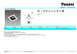
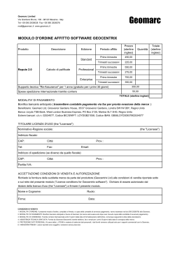
AVVERTENZE GENERALI/GENERAL INFORMATION
AEB Alternative Fuel Electronics
via dell’industria 20 42025 - Cavriago - Italy
ph. +39 0522 494401 - +39 0522 494414 (tech. assistance) - fax. +39 0522 494410
www.aeb.it - [email protected] - [email protected]
Dove fissare la Centralina / Where to install the control unit:
- LONTANO da possibili INFILTRAZIONI D’ACQUA.
- FAR from any WATER LEAKAGE
MP6C
- LONTANO da ECCESSIVE FONTI DI CALORE (esempio collettori di scarico).
- FAR from EXCESSIVE HEAT SOURCES (such as exhaust manifolds).
6 CYL. INJECTION CONTROL UNIT OBD
INSTALLATION MANUAL
- LONTANO dai CAVI DELL’ALTA TENSIONE.
- FAR from HIGH-VOLTAGE CABLES.
Fare delle buone connessioni elettriche evitando l’uso dei “RUBACORRENTE”.
Si tenga presente che la migliore connessione elettrica è la saldatura debitamente
isolata.
Create efficient electrical connections without using any “POWER TAPS”.
Properly insulated soldering is the most effective type of electrical connection.
Avvisare il cliente che in caso di rottura del fusibile dell’impianto a GAS, il Sistema ripristina i collegamenti dei dispostivi a cui è collegato. Si sconsiglia
vivamente di sostituire il fusibile con un’altro di amperaggio maggiore, cio’ puo’ provocare danni irreparabili.
Advise the customer that if the GAS system fuse burns, the connections of the devices to
which it is connected will be restored. It is strongly recommended not to replace the fuse
with another one with a higher amperage rating since it may cause irreparable damage.
Non aprire per nessun motivo la scatola della Centralina soprattutto con il motore in
moto o il quadro inserito, onde evitare danni irreparabili.
Si declina ogni responsabilità per danni a cose e persone derivati dalla manomissione
del proprio dispositivo da parte di personale non autorizzato con la conseguente perdita
di GARANZIA.
Do not open the Control Unit box for any reason, especially when the engine is running or the key
is in the ignition, to avoid irreparable damage.
Will not be held responsible for damage to property or injuries to persons if unauthorised
L’architettura dal sistema prevede l’utilizzo di un Relay esterno. Se non presente sul cablaggio
o in caso di sostituzione utilizzarne uno con le seguenti caratteristiche: 12V, 30A, contatto N.A.
The architecture of the system includes the use of an external relay. If not present in the wiring or
in the case of replacement use one with the following features: 12V, 30A, N.A. contact.
Specifiche tecniche / Technical specifications
Tensione di alimentazione / Supply voltage
Vbatt=10÷16V
Temperatura di funzionamento / Operating temperature
-40÷110°C
Fusibile di protezione / Protection fuse
MAX 15A
Assorbimento di corrente con attuatori disattivi / Current absorption Imax ≤0.5A
with the actuators disabled
Assorbimento di corrente in modalità standby / Current absorption Istandby ≤10 µA
in standby mode
Attuatori gestiti / Actuators managed
Uscita fili elettrovalvole gas / Wire output gas solenoid valves
Fino a 6 iniettori con caratteristiche:
Imax= 6A, Vbat max= 16V
up to 6 injectors with the following characteristics:
Imax=6A, Vbat max=16V
Pmax=25W, Imax=2A (potenza e corrente massima per ogni uscita con due uscite attive)
----------------------------------------------------Pmax=50W, Imax=4A (potenza e corrente massima con solo una uscita attiva)
Pmax=25W, Imax=2A (power and maximum
current for each output with two outputs enabled)
----------------------------------------------------Pmax=50W, Imax=4A (power and maximum
current with just one output enabled)
2-16
MP6C_AEB Rev. 111114-0
Il presente documento non può essere riprodotto né portato a conoscenza di terzi senza autorizzazione della ditta A.E.B. S.p.A.
This document may not be reproduced or made known to any third party without permission of the company AEB S.p.A.
SCHEMA DI MONTAGGIO PT GAS MAP/ ASSEMBLY PT GAS MAP DIAGRAM
COME FISSARE LA CENTRALINA / HOW TO INSTALL THE CONTROL UNIT
INSTALLAZIONE
ERRATA
INSTALLAZIONE
ERRATA
INSTALLAZIONE
CORRETTA
INCORRECT
INSTALLATION
INCORRECT
INSTALLATION
CORRECT
INSTALLATION
PRESSIONE
COLLETTORI (MAP)
PRESSURE
MANIFOLD (MAP)
RIDUTTORE
PRESSURE
REGULATOR
tyco
USCITA
GAS
SENSORE DI
PRESSIONE MAP E
TEMPERATURA GAS
GAS PRESSURE,
TEMPERATURE AND
MAP SENSOR
OUT
GAS
tyco
COLLETTORI DI
ASPIRAZIONE
INTAKE MANIFOLD
ATTENZIONE
WARNING
Fissare il cablaggio della
centralina in modo appropriato
(per esempio tramite fascetta) ad un
supporto nel vano motore per ridurre
al minimo le vibrazioni trasmesse alla
centralina
NO
Fix the wiring
control unit appropriately
(for example with clamp) to a support
in the engine compartment to reduce
vibration trasmitted to the ECU
tyco
OK
MP6C_AEB Rev. 111114-0
3-16
4-16
MP6C_AEB Rev. 111114-0
Il presente documento non può essere riprodotto né portato a conoscenza di terzi senza autorizzazione della ditta A.E.B. S.p.A.
Il presente documento non può essere riprodotto né portato a conoscenza di terzi senza autorizzazione della ditta A.E.B. S.p.A.
This document may not be reproduced or made known to any third party without permission of the company AEB S.p.A.
This document may not be reproduced or made known to any third party without permission of the company AEB S.p.A.
CONNETTORE
CENTRALINA GAS
tyco
PRESA PER
INTERFACCIA SERIALE
4 3 2 1
SENSORI
STANDARD A.E.B.
200
100
OPZIONALE
VIOLA
SONDA
LAMBDA 1
GRIGIO
300
MASSA
OPZIONALE
VIOLA/NERO
0
BIANCO
COLLEGAMENTO
GIRI MOTORE
SONDA
LAMBDA 2
GRIGIO/NERO
4X
MARRONE
1X
VERDE
1
INGRESSO GAS
RAIL INIETTORI
GAS 3 CILINDRI
RELE’ DI POTENZA
NERO
BIANCO
1/2
4/4
INIETTORI
BENZINA
VERDE
MASSA
BLU/BIANCO
COLLETTORI
D’ASPIRAZIONE
+
ELETTROVALVOLA
SERBATOIO
-
+12V SOTTO CHIAVE
BIANCO-ROSSO
NERO
ARANCIO
CABLAGGIO STACCA
INIETTORI BENZINA
AL SENSORE
TEMPERATURA ACQUA
ATTENZIONE!
Rispettare la sequenza dei
collegamenti, i fili BLU e BLUNERO devono
essere in corrispondenza
dell’iniettore gas marcato A, gli
altri di seguito come in figura.
I FILI DA INTERROMPERE
SONO I NEGATIVI
INIETTORI.
VERDE
NERO
VERDE-NERO
ROSSO
2
1
ELETTROVALVOLA
RIDUTTORE
ROSSO-NERO
BLU
BLU
NERO
BLU-NERO
1
1
8
9
16
GIALLO/GRIGIO
VERDE
FUSIBILE
MAX 15A
ATTENZIONE
IL CABLAGGIO RAIL INJ GAS CON
NASTRO ROSSO E IL CABLAGGIO
STACCA INIETTORI CON NASTRO
ROSSO VANNO ABBINATI SULLA
STESSA BANCATA
INGRESSO GAS
INIETTORI
BENZINA
NASTRO ROSSO
COLLETTORI
D’ASPIRAZIONE
ROSSO/NERO
NERO
BATTERY
MASSA
2
GIALLO/VERDE
+
E
RAIL INIETTORI
GAS 3 CILINDRI
G
CONNESSIONI PRESA OBD
(VEDERE PAGINA DEDICATA)
1
COMMUTATORE
F
2
NASTRO ROSSO
1
G
R
2
0
2
SENSORI STANDARD
0÷90 OHM
MASSA PER
SENSORE DI
LIVELLO
1
VERDE NON COLLEGARE
SENSORE DI PRESSIONE,
TEMPERATURA GAS E MAP
VERDE
A
2
BIANCO
B
1
C
BIANCO
MASSA
2
SENSORI STANDARD
A.E.B. TIPO 1050
7X
RPM
CABLAGGIO STACCA
INIETTORI BENZINA
VERDE
VERDE-NERO
ROSSO
ROSSO-NERO
BLU
BLU-NERO
ATTENZIONE!
Rispettare la sequenza dei
collegamenti, i fili BLU e BLUNERO devono
essere in corrispondenza
dell’iniettore gas marcato E, gli
altri di seguito come in figura.
I FILI DA INTERROMPERE
SONO I NEGATIVI
INIETTORI.
GAS CONTROLLER CONNECTOR
tyco
SERIAL INTERFACE SOCKET
4 3 2 1
OPTIONAL
VIOLET
A.E.B. STANDARD
SENSORS
200
100
OXYGEN
SENSOR 1
GRAY
300
GND
OPTIONAL
VIOLET/BLACK
0
WHITE
ENGINE RPM
REFERENCE
OXYGEN
SENSOR 2
GRAY/BLACK
4X
BROWN
1X
GREEN
7X
RPM
1
STANDARD SENSORS
0÷90 OHM
WHITE
1/2
GAS PRESSURE, TEMPERATURE
AND MAP SENSOR
GREEN
GAS INLET
LEVEL
SENSOR
GND
POWER RELE’
3 CYLINDERS GAS
RAIL INJECTORS
BLACK
4/4
PETROL
INJECTORS
GREEN
GND
BLUE/WHITE
FUEL TANK
SOLENOID VALVE
INTAKE
MANIFOLD
+
BLACK
WHITE-RED
+12 VOLT WITH IGNITION KEY
ORANGE
WARNING!
THE CONNECTOR OF THE GAS
INJECTOR A MUST
CORRESPOND TO THE BLUE WIRE
OF THE PETROL
CUT-INJECTOR CABLE.
THE WIRES TO INTERRUPT ARE
INJECTORS NEGATIVE WIRES.
PETROL CUT-INJECTOR CABLE
WATER TEMPERATURE SENSOR
GREEN
BLACK
GREEN-BLACK
RED
BLUE
2
1
PRESSURE REGULATOR
SOLENOID VALVE
RED-BLACK
BLUE
BLACK
BLUE-BLACK
1
8
9
16
YELLOW/GREY
GREEN
FUSE
MAX 15A
RED/BLACK
GND
3 CYLINDERS GAS
RAIL INJECTORS
PETROL
INJECTORS
INTAKE
MANIFOLD
RED STRIP
PETROL CUT-INJECTOR CABLE
BATTERY
E
GAS INLET
BLACK
-
+
1
OBD CONNECTION
(SEE PAGE DEDICATED)
WARNING
RAIL INJ GAS WIRING WITH RED STRIP
AND CUT INJECTORS WIRING WITH RED
STRIP MUST BE COMBINED ON THE
SAME BANK
2
YELLOW/GREEN
1
G
F
2
CHANGE OVER SWITCH
RED STRIP
1
G
R
2
0
2
DO NOT LINK GREEN WIRE
A
1
WHITE
B
2
GND
1
C
WHITE
2
A.E.B. STANDARD
SENSORS TYPE 1050
GREEN
GREEN-BLACK
RED
RED-BLACK
BLUE
BLUE-BLACK
WARNING!
THE CONNECTOR OF THE GAS
INJECTOR E MUST
CORRESPOND TO THE BLUE WIRE
OF THE PETROL
CUT-INJECTOR CABLE.
THE WIRES TO INTERRUPT ARE
INJECTORS NEGATIVE WIRES.
COLLEGAMENTO DEL CABLAGGIO STACCA INIETTORI
CONNECTION OF THE CUT INJECTOR WIRING
Come verificare il corretto collegamento del cablaggio stacca iniettori
How to check the correct connection of the cut injector wiring
Per verificare l’ottimale collegamento del cablaggio stacca iniettori occorre verificare prima di tutto,
sul connettore dell’iniettore benzina, su quale PIN arriva il positivo degli iniettori.
Per identificare quale dei due fili sia il positivo, seguire queste istruzioni:
- staccare tutti i connettori dagli iniettori;
- prendere un multimetro impostarlo per la lettura della tensione in continua;
- mettere il puntale negativo a massa;
- mettere il puntale positivo in uno dei due contatti del cablaggio iniettori;
- inserire il quadro e controllare immediatamente se arrivano +12 volt.
Se arrivano i +12 volt, questo è il positivo.
ATTENZIONE: il +12 volt iniettori su alcune vetture potrebbe essere temporizzato quindi
dopo alcuni secondi dall’accensione del quadro potrebbe venire a mancare. Consigliamo
di verificare la polarità di tutti i connettori del cablaggio iniettori, in modo da verificare
che tutti siano polarizzati allo stesso modo.
To check the correct connection of the cut injector wiring, you must first check, on the petrol injector
connector, on what PIN the injector positive is connected.
To identify which of the two wires is positive, do the following:
- detach all the connectors from the injectors;
- set a multimeter to measure DC voltage;
- put the negative probe to ground;
- put the positive probe into one of the two pins of the injector wiring;
- insert the key into the ignition and immediately check the multimeter reading.
If the multimeter reads +12 volts, that pin is the positive.
WARNING: the injector +12 volt on some cars might be timed; therefore the reading might
disappear a few seconds after the ignition is turned on. Check the polarity of all injector
wiring connectors to make sure that they are all polarised in the same way.
Per installare il cablaggio stacca iniettori occorre tagliare i fili negativi degli iniettori benzina, seguendo
l’ordine riportato in figura.
È molto importante il verso di collegamento, i fili rigati NERI vanno verso la centralina d’iniezione
benzina, gli altri verso gli iniettori.
The WHITE-RED wire should be connected to any of the injector positives.
Il filo BIANCO-ROSSO va collegato a uno qualsiasi dei positivi iniettori.
MP6C_AEB Rev. 111114-0
To install the cut injector wiring, cut the negative wires of the petrol injectors in the order indicated
in the figure.
The connection direction is very important. The BLACK striped wires should be installed toward the
petrol injection control unit and the others toward the injectors.
9-16
10-16
MP6C_AEB Rev. 111114-0
Il presente documento non può essere riprodotto né portato a conoscenza di terzi senza autorizzazione della ditta A.E.B. S.p.A.
Il presente documento non può essere riprodotto né portato a conoscenza di terzi senza autorizzazione della ditta A.E.B. S.p.A.
This document may not be reproduced or made known to any third party without permission of the company AEB S.p.A.
This document may not be reproduced or made known to any third party without permission of the company AEB S.p.A.
DESCRIZIONE DEI COLLEGAMENTI ALLA PRESA OBD
DESCRIPTION OF THE CONNECTIONS MADE ON THE OBD CONNECTOR
Questa Nuova Generazione di centraline GAS, attraverso la connessione alla presa OBD della vettura, permette
l’acquisizione di informazioni utili alla corretta messa a punto del veicolo.
Attraverso l’apposito software di collegamento della centralina GAS al PC, si potranno visualizzare alcuni parametri
di carburazione acquisiti dalla centralina BENZINA, quali:
• Correttori di carburazione (Fast e Slow).
• Tensione sulla sonda lambda posteriore.
Through connection to the vehicle’s OBD socket, this new generation of GAS control units makes it possible to acquire information useful for properly setting up the vehicle.
Several carburetion parameters acquired from the PETROL control unit can be seen using the special software for
connecting the GAS control unit to the PC, such as:
• Carburetion calibrators (Fast and Slow).
• Voltage on the rear lambda probe.
Munirsi di un tester palmare (COD. AEB214), e controllare il codice di connessione che viene restituito.
Nel caso in cui il palmare rilevi una connessione di tipo 1, 2, o 3, procedere come schematizzato in Figura 1.
Nel caso in cui il palmare rilevi una connessione di tipo 6, 7, 8 o 9, procedere come schematizzato in Figura 2.
Connect a hand-held tester (CODE AEB214), and check the type of connection.
If the tester reads connection types 1,2, or 3, proceed by following the diagram in figure 1.
If the tester reads connection types 6,7,8 or 9, proceed by following the diagram in figure 2.
ATTENZIONE: Nel caso in cui il tester palmare (COD. AEB214) rilevi altri tipi di connessione, non collegare nessun tipo di segnale.
ATTENTION: If the tester (CODE AEB214) reads a type of connection that is not stated above, do not
connect to any of the signals.
DESCRIZIONE CONNESSIONE
TYPE OF CONNECTION
Connessione tipo 1
ISO 9141-2
Connection type 1
ISO 9141-2
Connessione tipo 2
KWP-2000 Fast Init
Connection type 2
KWP-2000 Fast Init
Connessione tipo 3
KWP-2000 Slow Init
Connection type 3
KWP-2000 Slow Init
TIPO DI CONNESSIONE
PIN7
PIN7
Conettore OBD
vista frontale
CONNECTION DETAILS
1
8
9
16
FIG.1
OBD Connector
seen frontal
Connettere il cavo di colore VERDE al segnale proveniente dal PIN N°7 della presa OBD posta sull’autovettura.
ATTENZIONE: I cavi di colore GIALLO-VERDE e GIALLO-GRIGIO sono da isolare e non collegare.
1
8
9
16
FIG.1
Connect the GREEN wire to the signal found on PIN 7 of the OBD connector.
ATTENTION: The YELLOW-GREEN and YELLOW-GREY wires must be isolated and not connected.
DESCRIZIONE CONNESSIONE
TYPE OF CONNECTION
Connessione tipo 6
CAN Standard 250 Kbps
Connection type 6
CAN Standard 250 Kbps
Connessione tipo 7
CAN Extended 250 Kbps
Connection type 7
CAN Extended 250 Kbps
Connessione tipo 8
CAN Standard 500 Kbps
Connection type 8
CAN Standard 500 Kbps
Connessione tipo 9
CAN Extended 500 Kbps
Connection type 9
CAN Extended 500 Kbps
TIPO DI CONNESSIONE
PIN6
PIN6
1
Conettore OBD
vista frontale
8
FIG.2
OBD Connector
seen frontal
16
9
1
8
9
16
FIG.2
PIN14
PIN14
Connettere il cavo di colore GIALLO-VERDE al segnale proveniente dal PIN N°6 della presa OBD posta sull’autovettura ed il cavo di colore GIALO-GRIGIO al segnale proveniente dal PIN N°14 della medesima presa.
ATTENZIONE: Il cavo di colore VERDE è da isolare e non collegare.
MP6C_AEB Rev. 111114-0
CONNECTION DETAILS
11-16
Connect the YELLOW-GREEN wire to the signal found on PIN 6 and the wire YELLOW-GREY to PIN 14 of the
OBD connector.
ATTENTION: The GREEN wire must be isolated and not connected
12-16
MP6C_AEB Rev. 111114-0
Il presente documento non può essere riprodotto né portato a conoscenza di terzi senza autorizzazione della ditta A.E.B. S.p.A.
Il presente documento non può essere riprodotto né portato a conoscenza di terzi senza autorizzazione della ditta A.E.B. S.p.A.
This document may not be reproduced or made known to any third party without permission of the company AEB S.p.A.
This document may not be reproduced or made known to any third party without permission of the company AEB S.p.A.
FUNZIONAMENTO DEL COMMUTATORE
CHANGEOVER SWITCH OPERATION
Descrizione del funzionamento
Il commutatore che viene fornito nel kit dispone di un pulsante, 7 led luminosi e un cicalino inter
no.
LED GIALLO
FUNZIONAMENTO
A BENZINA
4 LED VERDI
LIVELLO
CARBURANTE
YELLOW LED PETROL
OPERATION
4 GREEN
LEDS - FUEL
LEVEL
PULSANTE
BUTTON
RED LED –
EMPTY TANK
RESERVE
LED VERDE
FUNZIONAMENTO
A GAS
SEGNALAZIONE
DIAGNOSI
LED ROSSO
RISERVA
GREEN LED GAS OPERATION
WITH
DIAGNOSTIC
SIGNAL
BUTTON
PULSANTE
This is used to select either the petrol or the gas fuel supply. Press the button one time to switch to
gas and press it again to return to petrol.
FUNZIONI LED VERDE
Rapid flashing – the control unit is prepared to start with petrol and switch automatically to GAS.
Steady on with yellow LED off – Gas operation.
Serve per selezionare il tipo di alimentazione, Benzina o Gas; premendolo si passerà da un tipo di
carburante all’altro.
Lampeggio veloce con led giallo fisso - la centralina è predisposta per l’avviamento a Benzina
ed il passaggio automatico a GAS.
Acceso fisso con led giallo spento - funzionamento a GAS.
FUNZIONI LED ROSSO + 4 LED VERDI
Indicatore di livello carburante; led ROSSO riserva, mentre i 4 led VERDI forniscono l’indicazione del livello carburante (1/4, 2/4, 3/4, 4/4). L’indicatore è acceso solo quando è selezionata la
modalità gas.
FUNZIONI LED GIALLO
Acceso fisso con led Verde spento - funzionamento a BENZINA.
Acceso fisso con led Verde lampeggiante - la centralina è predisposta per l’avviamento a Benzina
ed il passaggio automatico a GAS.
PASSAGGIO A BENZINA PER BASSA PRESSIONE GAS
Quando il commutatore è in riserva e la pressione del gas scende al di sotto di un valore prestabilito,
la centralina commuta automaticamente a benzina. Questo viene fatto per evitare che il motore possa
girare con una carburazione troppo magra danneggiando così il catalizzatore. Prima di ripassare la
vettura a Gas effettuare il rifornimento. Il passaggio a Benzina per bassa pressione Gas viene
segnalato dal commutatore con l’accensione del led GIALLO funzionamento a Benzina, l’accensione
alternata del LED ROSSO indicatore e dei 4 LED VERDI e con l’avviso acustico del cicalino interno.
Per riportare il commutatore al funzionamento normale è necessario premere una volta il PULSANTE,
rimarrà acceso il LED GIALLO per indicare che la vettura sta funzionando a Benzina ed il cicalino
smette di suonare.
MP6C_AEB Rev. 111114-0
Operating description
The changeover switch supplied with the kit has one button, 7 LEDs and an internal buzzer.
13-16
GREEN LED FUNCTIONS
RED LED + 4 GREEN LED FUNCTIONS
Fuel level indicator; reserve RED LED, while the 4 GREEN LEDS indicate the fuel level (1/4, 2/4,
3/4, 4/4). The indicator is illuminated only when the gas mode is selected.
YELLOW LED FUNCTIONS
Steady on with Green LED off – PETROL operation.
Steady on with flashing Green LED – the control unit is prepared to start with petrol and
switch automatically to Gas.
LOW GAS PRESSURE PETROL CHANGEOVER
When the changeover switch indicates the fuel tank is in reserve and the gas pressure drops below a
set value, the control unit automatically switches over to gas. This prevents the engine from running
with an excessively lean carburetion, thus damaging the catalyser. Before returning to gas operation, fill up. The changeover switch signals the changeover to petrol due to low gas pressure by
activating the internal buzzer, illuminating the YELLOW petrol operation LED and by illuminating the
RED LED in an alternating pattern with the 4 GREEN LEDS. To make the changeover switch return to
normal operation press the BUTTON one time; the YELLOW LED will remain on to indicate that the
car is operating with petrol and the buzzer turns off.
14-16
MP6C_AEB Rev. 111114-0
Il presente documento non può essere riprodotto né portato a conoscenza di terzi senza autorizzazione della ditta A.E.B. S.p.A.
Il presente documento non può essere riprodotto né portato a conoscenza di terzi senza autorizzazione della ditta A.E.B. S.p.A.
This document may not be reproduced or made known to any third party without permission of the company AEB S.p.A.
This document may not be reproduced or made known to any third party without permission of the company AEB S.p.A.
CONTRATTO DI LICENZA D’USO
USER LICENCE AGREEMENT
Leggere con attenzione le seguenti condizioni generali.
Si precisa che le seguenti condizioni si intendono integralmente conosciute ed accettate
al momento dell’utilizzo del prodotto.
Read the following general conditions carefully.
The user shall be deemed to be fully acquainted with the following conditions and to have
accepted them at the time of the software usage.
Oggetto del contratto
A.E.B. S.p.A. conserva la proprietà sul software (d’ora d’innanzi denominato “PROGRAMMA”) contenuto all’interno del prodotto A.E.B. da Voi acquistato.
Con la vendita del prodotto A.E.B. S.p.A. non cede alcun diritto sul PROGRAMMA ,ma solo la facoltà
di utilizzo quale utente finale dello stesso, secondo le modalità di cui alle presenti condizioni generali
e secondo le ulteriori condizioni e avvertenze presenti nel manuale d’uso.
A.E.B. S.p.A. è la sola titolare dei diritti di privativa sul PROGRAMMA, dei diritti morali e di utilizzazione economica, ivi compresi il diritto di riproduzione, traduzione, adattamento, trasformazione,
modificazione e distribuzione, sotto qualsiasi forma e senza limitazione alcuna, compresa la vendita
e la locazione anche di sue copie e delle sue versioni modificate od aggiornate.
A.E.B. S.p.A. è, altresì, titolare del diritto di proprietà su tutti i codici oggetto e su tutti i codici sorgente del PROGRAMMA.
Tutte le tecniche, gli algoritmi e i procedimenti contenuti nel Programma e nella relativa documentazione sono informazioni riservate di proprietà di A.E.B. S.p.A..
Il Licenziatario non potrà in alcun modo disporre dei codici oggetto e di codici sorgente, né farne oggetto di licenza o consentirne l’elaborazione, o impegnarne od altrimenti trasferire o in qualsivoglia
altro modo rendere disponibile a terzi il PROGRAMMA sia a titolo oneroso che gratuito.
Il Licenziatario non potrà concedere in locazione o in leasing il PROGRAMMA o parte di esso.
Scope of the agreement
A.E.B. S.p.A. retains ownership of the software (herein referred to as “PROGRAM”) required to use
the A.E.B. product you have purchased.
A.E.B. S.p.A. does not assign any rights to the PROGRAM through the sale of this product, but solely
the right of use as the end user of the said product, in accordance with the modalities described in
these general conditions and subject to further conditions and cautions given in the user manual.
A.E.B. S.p.A. is the sole holder of all copyright and other rights of the PROGRAM, the moral rights
and the rights of economic use, including the right of reproduction, translation, adaptation, transformation, modification and distribution, in any form and with no restrictions whatsoever, including the
sale and the lease of its copies and of modified or updated versions.
A.E.B. S.p.A. is also the holder of the intellectual property rights to all the object codes and to all
the source codes for the PROGRAM.
All the techniques, algorithms and procedures contained in the PROGRAM and in the associated documentation are considered confidential and property of A.E.B. S.p.A.
The Licensee may not dispose in any way of the object codes or source codes, or include them as
part of a licence, or allow them to be processed, pledged or otherwise transferred, or in any way to
make the PROGRAM available to third parties whether for sale or for free.
The Licensee shall not hire or lease the PROGRAM or any part of it.
Utilizzo del PROGRAMMA
Il Licenziatario non potrà riprodurre, tradurre, adattare, trasformare, modificare il PROGRAMMA o
qualsiasi parte in esso contenuta, né potrà incaricare terzi di eseguire tali attività.
Il Licenziatario non potrà copiare, nemmeno parzialmente, i manuali relativi al PROGRAMMA e l’eventuale materiale aggiuntivo (diagrammi logici o di flusso, ecc.) e non potrà consentirne l’uso a
terzi.
Il Licenziatario non potrà decodificare, decompilare, disassemblare, modificare o tradurre il PROGRAMMA, salvo quanto espressamente previsto da norme inderogabili di legge.
Il PROGRAMMA è concesso in licenza d’uso quale prodotto unitario.
Le sue singole parti componenti non possono essere separate per l’utilizzo in ambienti di elaborazione distinti o da parte di soggetti diversi dal Licenziatario.
In nessun caso A.E.B. S.p.A. sarà ritenuto responsabile dei danni diretti ed indiretti (inclusi il danno
per perdita o mancato guadagno o risparmio, o interruzione dell’attività, perdita di informazioni o
dati) derivante da una non corretta installazione del software o da un suo utilizzo non conforme alle
indicazioni riportate nel manuale d’istruzione.
Dal momento di interruzione della licenza o dallo scioglimento, per qualsiasi ragione verificatosi, del
presente contratto, rimane fermo il divieto d’uso, duplicazione o manipolazione del PROGRAMMA; il
Licenziatario sarà altresì tenuto ad osservare l’obbligo di confidenzialità per 5 anni dalla cessazione
del presente contratto.
Use of the PROGRAM
The Licensee may not reproduce, translate, adapt, transform, modify the PROGRAM or any part of
its contents, nor may it engage third parties to perform the said activities.
The Licensee may not copy, even in part, the manuals relating to the PROGRAM and any additional
material (logical diagrams or flow charts, etc.) and may not consent to their use by third parties.
The Licensee may not decodify, decompile, disassemble, modify or translate the PROGRAM, except
as expressly provided under mandatory statutory regulations.
This user licence is granted for the PROGRAM as a single product.
Its individual component parts may not be divided for use in separate processing environments or
by parties other than the Licensee.
Under no circumstances shall A.E.B. S.p.A. be liable for direct and indirect damage (including damage through loss of earnings or savings, or interruptions to activities, loss of information or data)
deriving from the incorrect installation of the software or from any use that does not comply with
the indications given in the user manual.
Any interruption to the licence or the cancellation of this agreement, for whatever reason this occurs, shall not detract from the prohibition to use, duplicate or tamper with the PROGRAM; the
Licensee will also undertake to observe the obligation of confidentiality for 5 years after the date
when this agreement expires.
Marchio
Tutti i marchi registrati e non, come ogni segno distintivo o denominazione, apposto sul PROGRAMMA e sulla relativa documentazione, restano di proprietà di A.E.B. S.p.A. senza che dalla stipulazione
del presente contratto derivi al Licenziatario alcun diritto sui medesimi.
Terzi, collaboratori e dipendenti del Licenziatario
Il Licenziatario si obbliga a far sì che quanti (dipendenti, collaboratori, clienti, fornitori, agenti)
hanno accesso al PROGRAMMA si vincolino al rispetto di tutti gli impegni qui assunti dallo stesso
Licenziatario.
Resta inteso che il Licenziatario rimane responsabile per qualsiasi inadempimento ascrivibile a coloro che hanno avuto accesso al PROGRAMMA.
Foro competente
Foro competente a conoscere delle controversie relative all’interpretazione ed applicazione del presente contratto è il foro di Reggio Emilia.
Legge applicabile
La legge applicabile al presente contratto è la legge italiana.
Per quanto non espressamente disciplinato troveranno applicazione le norme del codice civile italiano.
La nullità di una o più condizioni contenute nella presente licenza d’uso non comporterà in principio
la nullità dell’intero contratto.
MP6C_AEB Rev. 111114-0
15-16
Trademark
All trademarks, whether registered or not, and all distinctive signs or names used to mark the PROGRAM and the associated documentation shall remain the property of A.E.B. S.p.A. and the Licensee
shall derive no rights to the latter by entering into this agreement.
Third parties and the Licensee’s collaborators and employees
The Licensee undertakes to ensure that all persons (employees, collaborators, clients, suppliers,
agents) with access to the PROGRAM are bound to observe all the obligations assumed herein by
the Licensee.
It is hereby understood that the Licensee will be liable for any breach attributable to those individuals who have been given access to the PROGRAM.
Court with jurisdiction
The court with jurisdiction to settle any disputes concerning the construal and application of this
agreement will be the Court of Reggio Emilia.
Applicable law
This contract will be governed by Italian law.
In the event of any aspect not expressly provided for herein, reference will be made to the provisions of the Italian Civil Code.
The nullity of one or more conditions of this user license will not, in principle, determine the nullity
of the entire agreement.
16-16
MP6C_AEB Rev. 111114-0
Il presente documento non può essere riprodotto né portato a conoscenza di terzi senza autorizzazione della ditta A.E.B. S.p.A.
Il presente documento non può essere riprodotto né portato a conoscenza di terzi senza autorizzazione della ditta A.E.B. S.p.A.
This document may not be reproduced or made known to any third party without permission of the company AEB S.p.A.
This document may not be reproduced or made known to any third party without permission of the company AEB S.p.A.
Scaricare