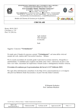
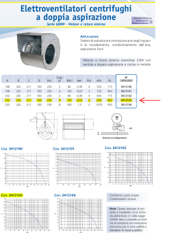
MasterPlant per refrigerazione e condizionamento MasterPlant for Refrigeration and Air-Conditioning Manuale d’uso User manual Vogliamo farvi risparmiare tempo e denaro! Vi assicuriamo che la completa lettura di questo manuale vi garantirà una corretta installazione ed un sicuro utilizzo del prodotto descritto. We wish to save you time and money! We can assure you that a thorough reading of this manual will guarantee correct installation and safe use of the product described. INDICE INTRODUZIONE........................................................................................................................................... 2 1.0 LA RETE SERIALE ................................................................................................................................ 2 1.1 RETE SERIALE RS485 (REFRIGERAZIONE)................................................................................................ 2 1.2 RETE SERIALE RS485 (CONDIZIONAMENTO) ............................................................................................. 3 1.3 RETE SERIALE RS422 (REFRIGERAZIONE)................................................................................................ 3 1.4 RETE SERIALE RS422 (CONDIZIONAMENTO) ............................................................................................. 3 2.0 REALIZZARE LE RETI........................................................................................................................... 4 2.1 LA RETE GLOBALE ............................................................................................................................... 4 2.2 MASTERPLANT IN LOCALE .................................................................................................................. 5 Rete RS485............................................................................................................................................ 5 Rete RS422............................................................................................................................................ 6 2.3 MASTERPLANT IN REMOTO................................................................................................................. 7 2.4 RETE CON GATEWAY........................................................................................................................... 8 2.5 L'INDIRIZZAMENTO DELLE PERIFERICHE ........................................................................................... 9 2.6 ELEMENTI DELLE RETI........................................................................................................................12 3.0 IL SOFTWARE DI SUPERVISIONE.......................................................................................................18 3.1 INTRODUZIONE....................................................................................................................................18 3.2 INSTALLAZIONE E AVVIO DI MASTERPLANT .....................................................................................18 3.3 CONFIGURAZIONE DI MASTERPLANT................................................................................................18 Configurazione del “Network”.................................................................................................................22 Configurazione dello “Scheduler” ...........................................................................................................26 Utilizzo di MasterPlant su computer remoto e locale. .............................................................................30 MasterPlant: barra di menù....................................................................................................................30 3.4 GENERALITA` DELLE FINESTRE DEI SUPERVISORI..........................................................................34 3.5 LE FINESTRE DI REPORT E DEGLI ALLARMI .....................................................................................38 Finestra di “Report” ...............................................................................................................................38 Finestra dei “Messaggi d’allarme”. .........................................................................................................39 4.0 MESSAGGI DI PCSLAVE......................................................................................................................40 5.0 REALIZZAZIONE DEI CAVI ..................................................................................................................41 6.0 INSTALLAZIONE DELLA SCHEDA MULTISERIALE ............................................................................44 7.0 RICERCA ED ELIMINAZIONE DEI GUASTI ..........................................................................................45 8.0 LISTA CODICI .......................................................................................................................................47 MasterPlant INTRODUZIONE MasterPlant è il nuovo programma di supervisione che permette di monitorare tutti i controlli Carel predisposti per la comunicazione seriale. MasterPlant opera in ambiente Windows per sfruttare la semplicità d’uso delle finestre e la standardizzazione dei comandi e dei menù. MasterPlant è proposto in due versioni: per impianti di refrigerazione e per impianti di condizionamento dell’aria. MasterPlant permette di centralizzare tutti i parametri di funzionamento degli impianti di refrigerazione commerciale e industriale (supermercati, celle, celle di stagionatura) che necessitano di un monitoraggio continuo per motivi di sicurezza, efficienza e rispetto delle normative di conservazione degli alimenti. La versione di MasterPlant per condizionamento permette di controllare tutti i parametri di funzionamento degli impianti di condizionamento nei quali è necessario una verifica continua delle grandezze igrometriche e di temperatura come per esempio in ambienti telematici, sale di controllo CED, impianti di raffreddamento dell’acqua. Tutto questo si attua mediante l’utilizzo di: • dispositivi di segnalazione (fax, sirena, report su carta e su file, connessione a MasterPlant su stazione PC remota, messaggi SMS); • registrazione e stampa normalizzata dei grafici dei valori di temperatura, umidità e pressione rilevati, stato dei dispositivi; • modifica semplice, intuitiva e sicura dei parametri dei controlli. Seguendo le indicazioni di questo manuale potrete: 1. realizzare correttamente la rete prescelta; 2. installare senza problemi sul vostro PC MasterPlant; 3. impostare facilmente MasterPlant per vostre esigenze. 1.0 LA RETE SERIALE MasterPlant può gestire anche contemporaneamente due differenti modalità di comunicazione tra PC e controlli Carel (linee seriali RS422 e RS485). MasterPlant controlla fino a quattro linee seriali ognuna configurabile nei due modi previsti. Di seguito vengono presentate tutte le modalità di connessione degli strumenti specifiche per le due reti. 1.1 RETE SERIALE RS485 (REFRIGERAZIONE) Di seguito sono elencate le caratteristiche di questa modalità di connessione: la rete ha bisogno solo di due fili più schermo (AWG20 / 22) per collegare gli strumenti per ogni linea si possono collegare fino a 200 strumenti predisposti la velocità di trasferimento dei dati è sempre a 19200 baud alcuni modelli di IR32 hanno implementata di fabbrica, a bordo, la scheda seriale Questi sono tutti gli strumenti che possono essere collegati alla rete seriale RS485 con due fili e schermo. Tutti i controlli per refrigerazione IR32 / IRDR / IR96; I controlli per refrigerazione IR32xEM: IR32*EM*00 Controlli universali IR32 / IRDR; Controlli per refrigerazione IR MPX; Controlli per refrigerazione plug-in; pCO (scheda 8 ingressi) 1 con software standard per la gestione di centrali frigorifere 3 Figura 1: Esempio di rete compressori (cod. EPSTDIFC2A) RS485 pCO (scheda 8 ingressi)1 con software standard per la gestione di celle di stagionatura (cod. EPSTDICS00); 1 pCO (scheda 8 ingressi) con software standard per la gestione di inseritore universale (cod. EPSTDIIU0A). 1 Usare schede pCO con codd. PCOB000A21 e PCOB000B21 Cod. Carel +030221210 - Rel. 1.1 - 06/06/00 2 MasterPlant 1.2 RETE SERIALE RS422 (REFRIGERAZIONE) La rete RS422 è più complessa da realizzare ma permette di collegare Macroplus e pCO direttamente alla rete, altri strumenti come IR32, CR72, Frigobase hanno bisogno di una scheda di interfaccia (ISA72, ASM2). Questi sono tutti gli strumenti che possono essere collegati alla rete seriale RS422 Controlli per refrigerazione IR32 / IRDR / IR96; Controlli universali IR32 / IRDR; Controlli universali CR72; Controlli per refrigerazione FRIGOBASE; Macroplus con software standard per la gestione di unità chiller 4 compressori (cod. EP000ICH00); (cod. EPSTDISN00); Macroplus con software standard per la gestione di utenze frigo Macroplus con software standard per la gestione di centrali frigo 5 compressori (cod. EPSTDIFC12); pCO con software standard per la gestione di centrali frigorifere 3 compressori (cod. EPSTDIFC2A); (cod. EPSTDICS00); pCO con software standard per la gestione di celle di stagionatura (cod. EPSTDIIU0A); pCO con software standard per la gestione di inseritore universale 1.3 RETE SERIALE RS485 (CONDIZIONAMENTO) Questi sono tutti gli strumenti che possono essere collegati alla rete seriale RS485 con due fili e schermo. Controlli universali IR32 / IRDR; Controlli per chiller µCHILLER e µCHILLER compact; Controlli per chiller µAC; pCO (scheda 8 ingressi)2 con software standard per la gestione di impianti di condizionamento (codd. EPSTD*CZ00, EPSTD*CZU0, EPSTDECGUA) pCO (scheda 8 ingressi)2 con software standard per la gestione di roof-top (cod. EPSTD*RT0A); pCO (scheda 8 ingressi)2 con software standard per la gestione di chiller con pompa di calore (cod. EPSTD*HP0A). 1.4 RETE SERIALE RS422 (CONDIZIONAMENTO) Di seguito indichiamo gli strumenti che possono essere collegati alla rete RS422. Controlli universali IR32 / IRDR; Controlli universali CR72; Controlli per chiller µCHILLER standard; Controlli per armadi di condizionamento MACROBASE + CDD; Controlli per umidificatori AFS: CDC, CDD, CDH, CDP, CDT, CDA; Macroplus con software standard per la gestione di unità chiller 4 compressori (cod. EP000*CH02). pCO con software standard per la gestione di unità Roof-Top (cod. EPSTD*RT0A) pCO con software standard per la gestione di unità per condizionamento - con opzione umidità e non (cod. EPSTD*CZ00), (cod. EPSTD*CZU0), (cod. EPSTD*CG0A); pCO con software standard per la gestione di unità chiller con pompa di calore (cod. EPSTD*HP0A); LEGENDA CT: terminatore di linea DV: Box di derivazione (compreso di cavo per la periferica) C1: cavo box/box CV: convertitore seriale RS232 / RS422 nd: controlli, interfacce ISA72, interfacce ASM2 Figura 2: Esempio schematico di rete RS422 2 Usare schede pCO con codd. PCOB000A21 e PCOB000B21. Cod. Carel +030221210 - Rel. 1.1 - 06/06/00 3 MasterPlant 2.0 REALIZZARE LE RETI 2.1 LA RETE GLOBALE Gli elementi costitutivi della rete sono: MasterPlant sul PC di supervisione locale è MasterPlant locale direttamente collegato agli strumenti da monitorare ed è in grado di gestire stampante, fax e un modem. MasterPlant remoto MasterPlant sul PC di supervisione remoto si collega tramite modem ad una installazione locale. Vedi Masterplant in remoto. Gateway è collegato ad una rete RS422 di supervisione e ad un modem via cavo seriale standard RS232 per entrare in comunicazione con MasterPlant su computer di supervisione remoto. Vedi rete con Gateway . Cod. Carel +030221210 - Rel. 1.1 - 06/06/00 4 MasterPlant 2.2 MASTERPLANT IN LOCALE In questa situazione il computer di supervisione è posizionato nell'installazione (tipicamente in una "sala controllo"). Installando un modem / fax è possibile trasferire tutti i dati e gli allarmi verso MasterPlant su PC remoto, oppure inviare dei fax o dei messaggi SMS, in caso d’allarme, a dei numeri preselezionati. Rete RS485 Componenti della rete RS485 • Computer di supervisione IMPORTANTE: il driver per la gestione delle linee seriali che viene installato con MasterPlant disabilita le porte seriali interne della COM3 alle successive. Non utilizzare quindi i modem interni o i modem sulle schede PCMCIA, vedi i seguenti paragrafi: • Scheda multiseriale (opzionale); • Cavi a sei fili di tipo telefonico (solo per IRDR, IR96); • Connettore a T per cavi tipo telefonico / doppini ritorti (solo per IRDR, IR96) • KIT Convertitore RS485 • Cavo di connessione RS485 • Controlli3 Realizzazione della rete RS485 Figura 3: Connessione convertitore RS232/485 - rete Utilizzare il cavo seriale fornito nel Kit convertitore RS232 / RS485 per Figura 4: Connessione IR32 - rete connettere il convertitore alla porta seriale del computer o della scheda multiseriale. Eventualmente frapporre l’adattatore 9/25 fornito nel kit. Collegare al convertitore i due fili del cavo per rete e la calza come da Fig.3. Collegare tutti gli strumenti alla rete come Fig. 4 e Fig.5. Per collegare i controlli IRDR e IR96 usare la morsettiera del connettore a T e cavo tipo telefonico 6 vie. Attenzione: 1. rispettare scrupolosamente la polarità dei fili D+ e D-; Figura 5: Connessione IRDR / IR96 - rete 2. la lunghezza massima della rete non deve essere superiore a 1000 m; le diramazioni non devono essere superiori a 5 m; 3. non realizzare biforcazioni della linea: collegamenti a stella; 4. tutti gli strumenti in rete devono essere alimentati da un proprio alimentatore d’isolamento (tranne per i modelli IRDR con 1 o 2 uscite digitali). Il secondario non deve essere collegato a terra; 5. in corrispondenza del morsetto più lontano dal convertitore Figura 6: Collocazione resistenze di fine linea seriale RS232 / RS485 inserire la resistenza da 120Ω ¼ W, fornita, tra i contatti D+ e D-; fare riferimento a Fig.6 6. evitare scrupolosamente che i cavi della linea di rete corrano in prossimità o, peggio, nella stessa canalina dei cavi di potenza. 3 Attenzione: per il collegamento del pCO in rete RS485 riferirsi al manuale (cod.+030221850) del pCO 5 Cod. Carel +030221210 - Rel. 1.1 - 06/06/00 MasterPlant Rete RS422 Componenti della rete RS422 • Computer di supervisione IMPORTANTE: il driver per la gestione delle linee seriali che viene installato con MasterPlant disabilita le porte seriali interne dalla COM3 alle successive. Non utilizzare quindi i modem interni o i modem sulle schede PCMCIA. Non installare schede audio or schede network cards, le quali potrebbero interferire con la scheda multiseriale, vedi: • Scheda multiseriale (opzionale); • Cavo di connessione RS422; • Convertitore seriale RS232/RS422; • Cavo per convertitore seriale RS232/RS422 • Box di derivazione per RS422; • Terminatore di linea; • Interfaccia ISA72; • Interfaccia ASM2; • Cavi a 6 fili di tipo telefonico; • Connettore a T per cavi tipo telefonico / doppini ritorti; • Resistenze di fine linea sulla rete dell’ISA72; • Cavo seriale RS232 - ISA72; • Controlli4. Carel consiglia vivamente l’utilizzo di connettori a T e di cavi Carel che garantiscano la corretta polarità e la qualità dei contatti. Figura 7: Rete ISA72 in RS422 Figura 8: Rete ISA72 in RS232 Realizzazione della rete RS422 Utilizzare il cavo per convertitore seriale per connettere il convertitore seriale RS232 / RS422 alla porta seriale del computer o della scheda multiseriale. Figura 9: Connettore a T sulla rete ISA72 con Collegare al convertitore la box di derivazione per RS422 con il resistenze di fine linea cavo di connessione RS422. Alla box di derivazione collegare, con un cavo di connessione RS422, i controlli (Macroplus, pCO) o le interfacce (ISA72, ASM2) desiderati. Dalla box di derivazione partire con un terzo cavo di connessione RS422 verso una ulteriore derivazione oppure se la derivazione è l’ultima della rete, innestare un terminatore di linea. Lunghezza massima della rete RS422 = 1000m. Ù controlli Realizzazione della rete ISA72 La scheda di interfaccia ISA72 può essere collegata in rete RS422 ad una box di derivazione. In questo modo si possono collegare fino a 16 ISA72 per ogni linea, max. 200 controlli (vedi anche Fig. 7. Si consiglia di utilizzare più linee seriali quando il numero degli strumenti è molto alto). La ISA72 può essere anche collegata direttamente alla seriale del PC locale: massimo una ISA72 per linea, massimo 15 controlli misti. Fig. 8. 4 ATTENZIONE: per il collegamento del pCO in rete RS422 riferirsi al manuale (cod.+030221850) del pCO 6 Cod. Carel +030221210 - Rel. 1.1 - 06/06/00 MasterPlant Collegare con cavo tipo telefonico 6 vie la ISA72 a un connettore a T per cavi telefonici. Da qui ripartire con cavo tipo telefonico verso lo strumento da collegare e con cavo ritorto a 3 coppie con schermo Figura 10: Rete RS422 con modem e stampante verso il connettore a T successivo. Nell’ultimo LEGENDA connettore a T inserire le resistenze di fine linea CT: terminatore di linea Box di derivazione per RS422 della rete dell’ISA72 (vedi Fig.9). Lunghezza DV: C1: cavo derivazione / derivazione massima della rete ISA72 = 300 m. Se la CV: convertitore seriale RS232 / RS422 lunghezza della rete ISA72 è inferiore ai 100 m è nd: Macroplus, pCO, ISA72, ASM2 possibile utilizzare cavo di tipo telefonico per collegare tra loro i connettori a T, anche se CAREL consiglia sempre l’uso di cavi ritorti e schermati, e il rispetto della corrispondenza cavo-morsetto indicato in Fig. 9 e in Tabella 4. Attenzione: 1. la lunghezza massima della rete RS422 non deve essere superiore a 1000 m; 2. la lunghezza massima della rete di collegamento dell’ISA72 agli strumenti non deve essere superiore a 300 m; le connessioni effettuate tramite cavo tipo telefonico non devono essere complessivamente superiori a 100m; 3. non realizzare biforcazioni della linea (collegamenti a stella); 4. tutti gli strumenti in rete devono essere alimentati da un proprio alimentatore d’isolamento (tranne per i modelli IRDR con 1 o 2 uscite digitali e per i CR72). Il secondario non deve essere collegato a terra; 5. nella rete dell’ISA72, in corrispondenza del connettore a T più lontano dalla ISA72, inserire le resistenze di fine linea da 120Ω ¼ W, morsetti 1-2 e 4-5; fare riferimento a (Figura ); 6. nella rete 422 in corrispondenza dell’ultimo box di derivazione usare il terminatore di linea (Figura 10). 7. evitare scrupolosamente che i cavi della linea di rete corrano in prossimità o, peggio, nella stessa canalina dei cavi di potenza. 2.3 MASTERPLANT IN REMOTO MasterPlant su PC remoto, tramite l'utilizzo di un modem e di una comune linea telefonica, dialoga fino a 1000 installazioni locali, che possono essere: • MasterPlant su computer di supervisione locale; • Gateway (massimo 200). Componenti per MasterPlant in remoto Gli strumenti necessari per realizzare la rete di Supervisione Remota CAREL sono relativi ai seguenti paragrafi: • Computer di supervisione; • Cavo di collegamento; • Modem LEGENDA: CT= terminatore di linea DV= Box di derivazione C1= cavo box / box C2= cavo box/periferica C3= cavo box /convertitore MO= Modem PCL= PC Locale PCR= PC Remoto (n)d= controllo Macroplus, pCO, o interfaccia ISA72, ASM2 Cod. Carel +030221210 - Rel. 1.1 - 06/06/00 7 MasterPlant 2.4 RETE CON GATEWAY Il Gateway è un “concentratore di dati” in sostituzione per alcune funzioni del MasterPlant su PC locale. Il Gateway permette infatti di raccogliere i parametri (senza però gestirne uno Figura 1: Rete RS422 con Gateway storico) e gli allarmi per un massimo di 16 unità tra LEGENDA: controlli (Macroplus, pCO) o interfacce (ISA72, CT= terminatore di linea DV= Box di derivazione ASM2). Utilizzando un modem ad esso collegato, C1= cavo box / box permette la comunicazione con un MasterPlant su C2= cavo box/periferica PC Remoto. Da PC Remoto sarà poi possibile MO= Modem C11= cavo collegamento Gateway / box di derivazione modificare i parametri dei vari strumenti collegati (n)d= controllo Macroplus, pCO, o interfaccia ISA72, ASM2 al Gateway e registrare tutte le situazioni d’allarme intervenute. La presenza di un relè permette la segnalazione degli allarmi anche tramite altre modalità (sirena, combinatore telefonico, ecc.). La Tabella 1 indica gli indirizzi delle variabili d’allarme dei controlli gestiti da MasterPlant per refrigerazione. La Tabella 2 indica gli indirizzi delle variabili d’allarme dei controlli gestiti da MasterPlant per condizionamento. Fare riferimento a questa tabella per la configurazione del Gateway (vedi manuale Gateway). Strumento Macroplus per Centrali frigorifere Macroplus per Chiller 4 compressori pCO per Centrali Frigorifere pCO per Celle di Stagionatura pCO per Inseritore Universale Frigobase plug-in Cr72 IR32 / IR96 / IRDR refrigerazione IR32 / IRDR universale Indice inferiore 13 15 50 19 11 1a - 25b 18 4 8 8 Indice superiore 51 15 51 19 11 12a - 36b 24 8 13 13 Tabella 1: Indice degli allarmi per Gateway controlli per refrigerazione Strumento Macroplus per Chiller 4 compressori pCO per Standard Roof-Top pCO per Standard Condizionatori pCO per Chiller con Pompa di Calore MicroChiller MicroChiller compact µAC Macrobase + CDD CDC, CDD, CDH, CDP, CDT CDA Cr72 IR32 / IRDR universale Indice inferiore 15 26 22 20 9a - 20b - 27c - 33d 5a - 18b 1 1a - 9b - 33c - 51d 1a - 9b 1a - 9b 4 8 Indice superiore 15 26 22 20 14a - 24b - 30c - 36d 16a - 22b 1 7a - 16b - 40c - 52d 7a - 16b 5a - 16b 8 13 Tabella 2 Indice degli allarmi per Gateway controlli per condizionamento Cod. Carel +030221210 - Rel. 1.1 - 06/06/00 8 MasterPlant Componenti per rete con Gateway Gli accessori necessari per la realizzazione di una rete completa sono relativi ai seguenti paragrafi: • Controlli; • Gateway; • Cavo programmazione Gateway • Cavo di collegamento per modem; • Modem; • Cavo di collegamento Gateway Attenzione: da non confondere con il Cavo di connessione RS422 • Cavo di connessione RS533; • Box di derivazione; • Terminatore di linea; • Interfaccia ISA72; • Cavi a 6 fili di tipo telefonico; • Connettore a T per cavi tipo telefonico / doppini ritorti; • Resistenze di fine linea sulla rete dell’ISA72; • Controlli Attenzione: seguire le avvertenze come per la rete RS422 pag. 9. 2.5 L'INDIRIZZAMENTO DELLE PERIFERICHE Tutti gli strumenti collegati alla rete devono avere un indirizzo per poter essere univocamente riconosciuti da MasterPlant. Qui di seguito viene spiegato come indirizzare gli strumenti collegati alle reti RS485 e RS422. Indirizzamento strumenti rete RS485 Gli indirizzi della rete RS485 possono andare da 1 a 199 per ogni linea. • Strumenti di controllo per refrigerazione e universali IR32 / IRDR / IR96 con schedine seriali codd. IR32SER00E / IRDRSER00E: l’indirizzo si ottiene sommando all’indirizzo impostato nello strumento (parametro H0 nei controlli per refrigerazione, parametro C32 nei controlli universali) un “offset” ottenuto posizionando i microinterruttori sulla schedina stessa. Vedi Figura 12: Offset realizzato con microinterruttori Fig. 12. • Controlli per refrigerazione IR32xE: Controlli con schedina seriale incorporata. Impostare il parametro H0 con un valore da 1 a 199. • Controlli per refrigerazione IR MPX: Controlli con schedina seriale incorporata. Impostare il parametro H0 con un valore da 1 a 199 nelle unità Master. Per quanto riguarda la modalità di collegamento di questi strumenti, fare riferimento al foglio istruzioni dello stesso. • Controlli pCO: impostare nella apposita maschera l’indirizzo da 1 a 199. • µ chiller compact. • µ AC • µ chiller • controlli PJ32: impostare il parametro H0 = 1..199. Indirizzamento strumenti rete RS422 Gli indirizzi della rete RS422 possono andare da 1 a 200 per ogni linea. Gli strumenti CR72, IR32, IRDR, IR96 devono essere collegati alla scheda di interfaccia ISA72 che, opportunamente configurata, permette di incrementare il numero di indirizzi assegnabili agli strumenti stessi. Cod. Carel +030221210 - Rel. 1.1 - 06/06/00 9 MasterPlant 1 ... 8 DL1 DL2 DL3 422 DL4 Reset B7 B8 B6 B1 232 Figura 13: ISA72 Nel caso si abbiano soluzioni con controlli “misti” bisogna impostare l’indirizzo (H0) degli IR32, IRDR per refrigerazione, IR96 se presenti, maggiore dell’indirizzo degli altri controlli [CR72 (C29), IR universali (C32)] collegati alla stessa ISA72 (indirizzo comunque non maggiore di 15). Ogni ISA72 è dotata di una serie di 8 microinterruttori che permettono di fissare un offset da sommare agli indirizzi degli strumenti collegati a tale ISA per creare indirizzi maggiori di 16 e comunque compresi entro 200. I microinterruttori seguono la codifica binaria con i seguenti pesi: Figura 14: Microinterruttori ISA72 microinteruttore n.1 microinteruttore n.2 microinteruttore n.3 microinteruttore n.4 microinteruttore n.5 microinteruttore n.6 microinteruttore n.7 microinteruttore n.8 peso 1 peso 2 peso 4 peso 8 peso 16 peso 32 peso 64 peso 128 Per ottenere un qualsiasi offset compreso tra 0 e 200 è sufficiente posizionare su ON i microinterruttori con il peso adatto in modo tale che la somma dei pesi dia l'offset desiderato. Esempio: per ottenere un offset uguale a 13 bisogna muovere su ON i microinteruttori n. 4, 3, 1 con i relativi pesi 8 + 4 + 1 = 13. Esempio di collegamento con ISA e IR32 refrigerazione: Se in una rete si vogliono collegare 20 IR32 per refrigerazione occorrono due ISA72. La prima ISA72 ha tutti i microinterruttori in posizione OFF per avere l'offset uguale a 0 e gli IR32 devono avere un indirizzo progressivo da 1 a 15 in modo tale che l'effettivo indirizzo dato dalla somma dell'offset + l'indirizzo degli IR32 sia: • indirizzo IR32 n.1 + offset ISA72 n1 = 1+0 = 1 • indirizzo IR32 n.2 + offset ISA72 n1 = 2+0 = 2 • ...... • indirizzo IR32 n.15 + offset ISA72 n1 = 15+0 = 15 La seconda ISA72 deve avere i microinterruttori da 1 a 4 in posizione ON (offset = 15) e gli indirizzi degli IR32 ugualmente in progressione da 1 a 5 in modo che la somma dell'offset della seconda ISA72 con gli indirizzi di questi IR32 sia: • indirizzo IR32 n.1 + offset ISA72 n2 = 1+15 = 16 • indirizzo IR32 n.2 + offset ISA72 n2 = 2+15 = 17 • ..... • indirizzo IR32 n.5 + offset ISA72 n2 = 5+15 = 20. Il risultato delle somme sulla colonna di destra rappresenta quindi il vero indirizzo di ogni IR32 da utilizzare nella configurazione del supervisore. Controllo per condizionamento/refrigerazione CR72 Il parametro che rappresenta l'indirizzo è C29 e gli indirizzi utilizzabili vanno da 1 a 16. Per produrre indirizzi superiori utilizzare l’offset impostabile sulla ISA72. L'interfaccia seriale dei CR72 va collegata all'ISA72. Il CR72 può essere collegato solo in rete RS422 Controllo per refrigerazione IR32/IRDR refrigerazione/IR96 Il parametro che rappresenta l'indirizzo è H0 e gli indirizzi utilizzabili vanno da 1 a 15. Per produrre indirizzi superiori utilizzare l’offset impostabile sulla ISA72. L'interfaccia seriale degli IR32 va collegata all'ISA72. Controllo per condizionamento/refrigerazione IR32 / IRDR universale Cod. Carel +030221210 - Rel. 1.1 - 06/06/00 10 MasterPlant Il parametro che rappresenta l'indirizzo è C32 e gli indirizzi utilizzabili vanno da 1 a 15. Per produrre indirizzi superiori utilizzare l’offset impostabile sulla ISA72. L'interfaccia seriale degli IR32 va collegata all'ISA72. Controllo per condizionamento µCHILLER Il parametro che rappresenta l'indirizzo è HA e gli indirizzi utilizzabili vanno da 1 a 15. Per produrre indirizzi superiori utilizzare l’offset impostabile sulla ISA72. L'interfaccia seriale del µCHILLER va collegata all'ISA72 in rete RS422. Cod. Carel +030221210 - Rel. 1.1 - 06/06/00 11 MasterPlant Controllo per condizionamento µchiller Per collegare µCHILLER alla rete RS485 è necessaria la scheda MCHSER4850, sulla quale è possibile produrre indirizzi superiori utilizzando l’offset impostabile nello stesso modo indicato per le schede seriali IRXXSER00E. Controllo per condizionamento µCHILLER Compact Il parametro che rappresenta l'indirizzo è HA e gli indirizzi utilizzabili vanno da 1 a 199. Il µCHILLER Compact può essere collegato solo in rete RS485. Controllo per condizionamento µAC Il parametro che rappresenta l'indirizzo è Ho e gli indirizzi utilizzabili vanno da 1 a 200. Il µAC può essere collegato solo in rete RS485. Controllo condizionamento / refrigerazione Macroplus / pCO In ogni Macroplus / pCO c'è una maschera apposita per l'impostazione del numero di identificazione. Fare riferimento al manuale dell'applicativo per individuare la posizione della maschera. Macroplus può essere collegato solo in rete RS422. Controllo per condizionamento Chillbase, Macrobase + CDD, CDA, CDC, CDD, CDH, CDP, CDT Per ogni interfaccia ASM2 è collegabile un solo controllo Chillbase, oppure un controllo per armadi di condizionamento Macrobase +CDD, oppure i controlli per umidificatori AFS sopracitati (un per ogni ASM2). L'indirizzo si imposta per mezzo dei microinterruttori posti sulla ASM2. Gli indirizzi utilizzabili vanno da 1 a 15. Fare riferimento alla documentazione della ASM2. Il Chillbase può essere collegato solo in rete RS422. Controllo per refrigerazione Frigobase Per ogni interfaccia ASM2 sono collegabili 2 Frigobase impostando l'indirizzo per mezzo dei microinterruttori della ASM2. Gli indirizzi utilizzabili vanno da 1 a 15. Fare riferimento alla documentazione della ASM2. Per distinguere i due Frigobase di una unica ASM bisogna muovere i tre ponticelli sul retro della scheda Frigobase n.2. Accertarsi quindi che i ponticelli del Frigobase n.1 siano in posizione 0 mentre i ponticelli del Frigobase n.2 siano in posizione 1. Il Frigobase può essere collegato solo in rete RS422. Plug-in Il parametro che rappresenta l’indirizzo è H0 e gli indirizzi utilizzabili vanno da 1 a 199. Questo strumento può essere collegato solo alla rete RS485. Disponibile solo per modelli TOP. 2.6 ELEMENTI DELLE RETI Tutti gli accessori necessari per la realizzazione delle reti di supervisione CAREL sono presentati qui di seguito. Gli schemi per la costruzione dei cavi sono a REALIZZAZIONE DEI CAVI. Computer di supervisione Per l’installazione di MasterPlant su PC di supervisione locale o remoto, si consiglia di utilizzare un computer compatibile 100% IBM con le seguenti minime caratteristiche. • PC Pentium 133 Mhz • Windows95/98 • RAM 32 MB; • Hard disk con 10 MB liberi per l’installazione e approssimativamente 6 MB per ogni strumentino connesso; • floppy drive da 3,5" 1.44 MB; • tastiera; • mouse; • scheda video e monitor VGA; • porta seriale RS232; • modem esterno (quando necessario). AVVERTENZA: non installare schede audio o schede di rete che potrebbero interferire con la scheda multiseriale (quando presente); non installare alcun modem interno, non funzionerebbe. Se necessario installare un modem esterno da collegare alla porta seriale disponibile, comunque non sulla multiseriale. Cod. Carel +030221210 - Rel. 1.1 - 06/06/00 12 MasterPlant Convertitore seriale RS232/RS422 cod. CONV422CL1 Converte lo standard di trasmissione dati RS232 del computer nello standard RS422 adottato dalla rete CAREL consentendo il collegamento dei controlli CAREL ad una porta seriale RS232 del computer. Ad ogni porta seriale COM libera si può associare una linea di rete cui possono essere connesse fino a più di 16 periferiche5, con un limite massimo di 200 controlli (vedi oltre). Cavo per convertitore seriale RS232/RS422 cod. 98C161C003 connettore lato computer 25 poli cod. 98C161C004 connettore lato computer 9 poli Cavo di collegamento tra il computer ed il convertitore con due codici: per connettore lato PC a 9 oppure 25 poli. Lunghezza massima 2,5 m. Cavo di connessione RS422 cod. 98C145C024 É un particolare cavo adatto alla trasmissione dati del tipo AWG24 a 6 fili, schermato e con filo di continuità. CAREL fornisce questo cavo provvisto di connettore 9 vie e con lunghezza standard di 10 m. É utilizzabile per le connessioni tra le box di derivazione, tra convertitore seriale RS232/RS422 e box di derivazione e tra box di derivazione e periferiche. Box di derivazione per RS422 (Kit box + cavo) cod. 98C145C034 Box di derivazione che permette il collegamento di ogni periferica alla linea seriale. All'ultima box di derivazione va connesso un terminatore di linea. La box di derivazione viene fornita con un cavo della lunghezza di 2.5 m, da utilizzare per connettere la box alla periferica. Terminatore di linea cod. 98C145C025 All'ultima box di derivazione di ogni linea seriale va connesso un piccolo dispositivo elettronico che permette di chiudere la linea, in modo da eliminare gli effetti negativi delle riflessioni. Interfaccia ISA72 cod. ISA7200001 L’interfaccia seriale ISA72 permette il collegamento dei seguenti strumenti , alla rete di supervisione CAREL: • CR72; • IR32 / IRDR per refrigerazione e universali; • IR96. • µ Chiller Ciascuna ISA72 supporta: • fino a 16 CR72, o IR32 / IRDR universali, oppure • fino a 15 IR32 / IRDR refrigerazione, IR96,µ Chiller, oppure • fino a 15 controlli “misti” (16 se non si utilizzano IR32 / IRDR refrigerazione, IR96, µ Chiller) I LED posti sulla scheda consentono di verificare lo stato della comunicazione tra MasterPlant e gli strumenti collegati alla ISA72 stessa. 5 Acceso Spento DL 1 verde non usato non usato Lampeggia non usato DL 2 verde DL 3 verde DL 4 rosso Alimentazione OK Assenza comunicazione verso i Assenza comunicazione verso il Mancanza alimentazione controlli supervisore ISA72 in comunicazione verso ISA72 in comunicazione verso il Autotest della ISA72 in corso gli strumenti supervisore Tabella 3: Descrizione dei LED dell'ISA72 Per periferiche si intendono: Macroplus, pCO, ISA72, ASM2 Cod. Carel +030221210 - Rel. 1.1 - 06/06/00 13 MasterPlant Sulla scheda sono presenti tre connettori a pettine (pin B7 B7 B7 B7 B8 B8 B8 B8 strip) per la selezione della velocità di comunicazione tra la B6 B6 B6 B6 ISA72 e il computer di supervisione.Nella Fig. 15 vengono (A) 1200 (B) 1200 (C) 2400 (D) 4800 indicate le modalità di impostazione della velocità di Figura 15: Impostazione della velocità della ISA72 comunicazione. Prima di modificare la posizione di fabbrica (B) del ponticello e di conseguenza la velocità di comunicazione, assicurarsi che sulla stessa linea non siano presenti altre periferiche con velocità diverse (Macroplus e pCO) e che il supervisore sia impostato correttamente (Vedi Fig. 21 Finestra Local Setup). Cavi a 6 fili di tipo telefonico cod. S90CONN000 S90CONN001 S90CONN002 1,5 m; 3 m; 0,8 m. 1 ÷ 6 ALTO Figura 16: Cavo tipo telefonico 6 vie BASSO 1 ÷ 6 Gli strumenti IR32, IRDR, IR96, CR72 possono essere connessi all’ISA72 usando cavi tipo telefonico a 6 fili. Carel fornisce questi cavi in tre misure. Cavi di lunghezza diversa sono a cura del cliente. Attenzione: come si vede in Fig. 16, un connettore è girato di 180°. La rete deve essere chiusa tramite un terminatore di linea (Vedi oltre). Connettore a T per cavi tipo telefonico / doppini ritorti (cod. TCONN60000) Questo connettore (Fig. 17) permette di creare una derivazione sulla linea alla ISA72 verso gli strumenti. A questo connettore si possono collegare sia cavi telefonici, sia cavi a tre doppini ritorti con le modalità della Tabella 4. 120 Ω Morsetto 0 1 2 3 4 5 6 Funzione Earth Data Data + Gnd Clock Clock + Gnd Connessione Schermo Prima coppia 6 5 120 Ω 4 3 2 1 0 Ground (terza coppia) Seconda coppia Ground (terza coppia) Figura 17: Connettore a T sulla rete ISA72 con terminatore di linea Tabella 4: Schema connessione coppie di doppini Resistenze di fine linea sulla rete dell’ISA72 Per realizzare questo terminatore deve essere usato un connettore a T. Vedi Fig. 17. La connessione deve essere fatta usando due resistenze del valore di 120 Ω a 1/4 W: una collegata tra i morsetti 1-2 (Data+ e Data-) e l’altra tra 4-5 (Clock+ e Clock-). Vedi Tabella 4. Questo terminatore di linea va posto nel punto della rete più lontano dalla scheda ISA72. Cavo seriale RS232 - ISA72 cod. 98C353P003 È possibile collegare direttamente al computer una ISA72 attraverso questo cavo di 2,5 m. Ricordarsi di cambiare in posizione RS232 il ponticello B1 al centro della ISA72 (Fig. 13: ISA72). Fare riferimento a REALIZZAZIONE DEI CAVI per la realizzazione dello stesso. Lunghezza max. 10 m, schermato. Cod. Carel +030221210 - Rel. 1.1 - 06/06/00 14 MasterPlant ASM2 cod. ASM2/A0000 (MasterPlant per refrigerazione) L’interfaccia ASM2 consente l’allacciamento ad un sistema di supervisione CAREL, tramite linea seriale RS422, dei regolatori di temperatura FRIGOBASE. Ogni ASM2 supporta massimo 2 Frigobase purché allocati nello stesso quadro (Cavo connessione ASM2 / Frigobase fornito con lunghezza di 1,5 m). cod. ASM2000000, (MasterPlant per condizionamento) L’interfaccia ASM2000000 consente l’allacciamento ad un sistema di supervisione CAREL, tramite linea seriale RS422, dei regolatori di umidità CDA, CDC, CDD, CDH, CDP, CDT, e dei controlli per condizionamento MacroBase + CDD. Controlli (MasterPlant per la refrigerazione) I controlli che possono essere gestiti dal supervisore MasterPlant per refrigerazione sono: Controlli IR32 refrigerazione / universale Codice scheda seriale (opzionale) per rete RS422 cod. IR32SER000 per rete RS485 cod. IR32SER00E IR96 (per refrigerazione) per rete RS422 cod. IRDRSER000 per rete RS485 cod. IRDRSER00E IRDR refrigerazione / universale per rete RS422 cod. IRDRSER000 per rete RS485 cod. IRDRSER00E IR32xEM (per refrigerazione) predisposto solo per rete RS485 IR MPX (per refrigerazione) predisposto solo per rete RS485 plug-in (per refrigerazione solo modelli Top) PJOPZ48500 (solo per rete RS485) CR726 (tutti i codici tranne i seguenti: CR72130000 e CR72230000) CR72SER000 (solo rete RS422) FRIGOBASE ASM2/A0000 (solo rete RS422) Macroplus con software standard per unità chiller 4 compressori MNEWRS4220 (solo rete RS422) (cod. EP000ICH00) Macroplus con software standard per utenze frigorifere (cod. EPSTDISN00) MNEWRS4220 (solo rete RS422) Macroplus con software standard per centrali frigo 5 compressori MNEWRS4220 (solo rete RS422) (cod. EPSTDIFC12) pCO* con software standard per centrali frigorifere 3 compressori per rete RS422 cod. PCOSER0000 (cod. EPSTDIFC2A) per rete RS485 cod. PCOSER4850 pCO* con software standard per celle di stagionatura (cod. per rete RS422 cod. PCOSER0000 EPSTDICS00) per rete RS485 cod. PCOSER4850 pCO* con software standard per inseritore universale (cod. per rete RS422 cod. PCOSER0000 EPSTDIIU0A); per rete RS485 cod. PCOSER4850 Tabella 5: Controlli (MasterPlant per la refrigerazione) 6 AVVERTENZA: per i modelli CR72*00000, CR72*10000, CR72*20000, i valori dei seguenti parametri devono rimanere quelli di default: C05=°C (unità di misura), C06=1 (numero di decimali). Per quanto riguarda il codice CR72*40000 i valori dei seguenti parametri devono rimanere quelli di default: C05=°C (unità di misura), C06=1 (numero di decimali) C10=-1.1 (tipo d’ingresso in tensione), C11=0 (valore corrispondente alla minima tensione ammissibile), C12=100 (valore corrispondente alla massima tensione ammissibile). * ATTENZIONE: Nel caso in cui vengano utilizzate le schedine di comunicazione per rete RS485 è indispensabile usare schede pCO a 8 ingressi. 15 Cod. Carel +030221210 - Rel. 1.1 - 06/06/00 MasterPlant Controlli (MasterPlant per il condizionamento) I controlli che possono essere gestiti dal sistema di supervisione MasterPlant per condizionamento sono: Controlli Codice scheda seriale (opzionale) IR32 universale per rete RS422 cod. IR32SER000 per rete RS485 cod. IR32SER00E IRDR universale per rete RS422 cod. IRDRSER000 per rete RS485 cod. IRDRSER00E CR726 (tutti i codici tranne i seguenti: CR72130000 e CR72SER000 (solo rete RS422) CR72230000) microchiller MTASERIAL0 (solo rete RS422) microchiller compact MCHSMLSER0 (solo rete RS485) µAC MAC2SER0000 (solo rete RS485) MACROBASE + CDD ASM2000000 (solo rete RS422) Controlli per umidità CDA, CDC, CDD, CDH, CDP, CDT ASM2000000 (solo rete RS422) Macroplus con software standard per la gestione di unità chiller 4 MNEWRS4220 (solo rete RS422) compressori (cod. EP000*CH02). pCO con software standard per la gestione di unità Roof-Top per rete RS422 cod. PCOSER0000 (cod. EPSTD*RT0A) per rete RS485 cod. PCOSER4850 Pco* con software standard per la gestione di unità per per rete RS422 cod. PCOSER0000 condizionamento - con opzione umidità e non - (codd. per rete RS485 cod. PCOSER4850 EPSTD*CZ00, EPSTD*CZU0, EPSTDECGUA) pCO* con software standard per la gestione di unità chiller per rete RS422 cod. PCOSER0000 reversibile (cod. EPSTD*HP0A) per rete RS485 cod. PCOSER4850 Tabella 6: Controlli (MasterPlant per il condizionamento Gateway cod. GATEWAY000 Il Gateway "raccoglie" i dati delle periferiche (massimo 16 strumenti per ogni Gateway), li converte in segnali adatti alla trasmissione via modem e li invia verso MasterPlant su PC di supervisione remoto. Deve essere programmato tramite PC e a questo proposito CAREL fornisce il software di inizializzazione ed il relativo cavo di collegamento (si veda il paragrafo successivo, il manuale Gateway e il capitolo RETE CON GATEWAY). Cavo programmazione Gateway cod. 98C429P006 connettore verso computer 25 poli 98C429P005 connettore verso computer 9 poli Questo cavo viene utilizzato per collegare il Gateway ad un PC per permetterne la configurazione. Cavo collegamento Gateway - derivazione a T per RS422 Attenzione: da non confondere con il Cavo di connessione RS422 cod. 98C136C004. Questo cavo viene utilizzato per collegare il Gateway alla derivazione a T. É un cavo particolare (vedi capitolo REALIZZAZIONE DEI CAVI) adatto alla trasmissione dati del tipo AWG24 a 6 fili, schermato e con filo di continuità. CAREL fornisce questo cavo provvisto di connettore 9 vie e con lunghezza standard di 5 m. *AVVERTENZA: Nel caso in cui vengano utilizzate le schedine di comunicazione seriale RS485 è indispensabile utilizzare schede pCO a 8 ingressi 16 Cod. Carel +030221210 - Rel. 1.1 - 06/06/00 MasterPlant Cavo di collegamento per modem a cura del cliente Cavo di collegamento seriale tra il computer ed il modem; fare riferimento al capitolo REALIZZAZIONE DEI CAVI per la realizzazione dello stesso (in ogni caso si tratta di un cavo seriale standard per personal computer), tipicamente viene fornito con il modem. Lunghezza massima 10 m. ATTENZIONE: alcuni adattatori 25/9 che si trovano normalmente in commercio (tipo quelli utilizzati per collegare i mouse ) non sono adatti per il collegamento dei modem, in quanto non utilizzano tutti i 9 pin presenti. KIT Convertitore RS485-RS232 cod. PC485KIT00 Il kit contiene: • Convertitore RS485-RS232: il collegamento tra gli strumenti Carel che usano la comunicazione RS485 e il PC è reso possibile utilizzando questo convertitore. La connessione alla rete RS485 avviene attraverso un connettore estraibile a tre contatti (i segnali di trasmissione, di ricezione e lo schermo). Lo stato delle linee di trasmissione (TX), ricezione (RX) e di alimentazione (PWR) è indicato da tre LED. • Cavo di collegamento per modem: cavo seriale standard per collegare il lato RS232 del convertitore RS485-RS232 (femmina) e la porta RS232 (maschio) del PC. • Trasformatore 220 Vac-12 Vac, 3VA: serve per alimentare il convertitore RS485-RS232. • Adattatore 9/25: è un adattatore da frapporre tra la porta seriale a 9 pin del computer (RS232) e il cavo seriale per il convertitore RS485-RS232 con 25 pin. È possibile utilizzare questo adattatore anche per il collegamento di un modem alla porta seriale del computer. • Resistenze di terminazione: resistenze da 120Ω ¼W. Una resistenza va inserita alla fine della linea RS485. Vedi Fig. 6. Cavo di connessione RS485 È un particolare cavo adatto alla trasmissione dati del tipo AWG20 / AWG22 a 2 fili a coppia ritorta, schermato. CAREL non fornisce questo cavo (vedi sezione REALIZZAZIONE DEI CAVI). È utilizzabile per le connessioni tra Convertitore RS232/RS485 e periferiche. Modem a cura del cliente. I modem utilizzati da CAREL sono con protocollo standard Hayes a range esteso di comandi. La modalità di trasmissione è la seguente: • 1200 - 19200 baud • 8 bit dati • 2 bit di stop • nessuna parità Modem consigliati sono: USRobotics® Sportster® 14.400 / 28.800; Trust® AE1414 IMPORTANTE: il driver per la gestione delle linee seriali che viene installato con MasterPlant disabilita le porte seriali interne dalla COM3 alle successive. Non utilizzare quindi i modem interni o i modem sulle schede PCMCIA. Scheda multiseriale cod. MULTISER40 La scheda multiseriale è indispensabile qualora si debbano utilizzare nel computer di supervisione locale più porte seriali di quelle in dotazione al PC. La scheda deve essere propriamente configurata e installata all’interno del computer. Fare riferimento ad INSTALLAZIONE DELLA SCHEDA MULTISERIALE. Cod. Carel +030221210 - Rel. 1.1 - 06/06/00 17 MasterPlant 3.0 IL SOFTWARE DI SUPERVISIONE 3.1 INTRODUZIONE MasterPlant interroga ciclicamente (“polling”) le periferiche mantenendo il suo database continuamente aggiornato. La trasmissione è ottimizzata in quanto vengono inviate solo le variabili i cui valori sono cambiati rispetto all'interrogazione precedente. Il tempo di ciclo di interrogazione è in funzione del numero di periferiche (massimo 800) collegate in rete. MasterPlant permette in qualsiasi momento l'aggiornamento del numero strumenti connessi in rete; in questo modo è possibile configurare la rete da parte dello stesso operatore. Il software riceve, mostra, memorizza e attiva delle procedure personalizzabili per tutti gli allarmi rilevati dalle periferiche. Sarà inoltre possibile eseguire una stampa degli allarmi rilevati in due diversi modi: 1. stampa immediata di tutti gli allarmi rilevati fino al momento in cui la si esegue; 2. stampa di ogni singolo allarme a fronte dell’allarme stesso. É disponibile anche la stampa dei grafici delle grandezze rilevate dalle sonde connesse ai regolatori. MasterPlant su PC remoto, una volta effettuato il collegamento via modem, permette di modificare setpoint e parametri relativi alle varie unità connesse a MasterPlant su PC locale o al Gateway. Il PC remoto, non essendo connesso permanentemente al computer locale e quindi alle periferiche, non può eseguire la memorizzazione dei dati storici. Questi possono essere trasferiti via modem da PC locale a PC remoto per la visualizzazione su singole schermate e quindi per la stampa. 3.2 INSTALLAZIONE E AVVIO DI MASTERPLANT Predisposizione del monitor Predisporre il monitor in modalità grafica 640x480x65536 colori (16bit) per avere la migliore visualizzazione. Per fare ciò aprire il pannello di controllo di Windows, fare doppio click sull’icona Schermo e scegliere Impostazioni. AVVERTENZA: Se è stata già installata una versione precedente di Carel MasterPlant è necessario eliminare la vecchia directory contenente il programma prima di avviare una nuova installazione di Carel MasterPlant. Non reinstallare il supervisore sovrascrivendo la vecchia directory. CD e dischetti di installazione di MasterPlant Figura a - Predisposizione del video Cod. Carel +030221210 - Rel. 1.1 - 06/06/00 MasterPlant può essere installato direttamente dal CD se il computer dispone di un lettore CD, altrimenti da un qualsiasi computer dotato di lettore CD è possibile creare i dischetti di installazione da usare nel computer senza lettore. 18 MasterPlant Installazione di MasterPlant da CD: Con l’inserzione del CD nel lettore, automaticamente il programma di installazione si avvia richiamando il browser internet predefinito. È consigliato l’uso di Internet Explorer 4.0 o successivi. Viene presentata una pagina di introduzione al MasterPlant. Scegliere la lingua della pagina (italiano - inglese) facendo click sul simbolo della bandiera. Sul lato sinistro sono presenti tre menu a tendina per: 1. l’installazione di MasterPlant per refrigerazione da CD nella lingua desiderata 2. l’installazione di MasterPlant per condiziona-mento da CD nella lingua desiderata 3. creazione dei dischetti di installazione di MasterPlant per i computer senza lettore CD Figura b - Videata iniziale programma di installazione 1. Scegliere MasterPlant per refrigerazione (Figura b, punto ) o condizionamento (Figura b, punto ) nella lingua desiderata. Fare click sul relativo pulsante “INSTALLA” 2. Nella finestra che compare successivamente (Figura c), scegliere di eseguire il programma (prima opzione), non salvarlo. Fare click su “Ok” 3. La successiva finestra di avviso (Figura d) chiede conferma per l’esecuzione del programma di installazione. Fare click su “Si” 4. A questo punto inizia la copia dei file sul computer. La finestra successiva richiede la cartella di destinazione. Quella predefinita è C:\MPLANT che si consiglia di mantenere. Nella stessa finestra viene richiesto di specificare se si vuole installare MasterPlant per PC locale o per PC remoto. MasterPlant su PC locale avverte che l’installazione preclude l’uso delle schede PCMCIA (PC portatili) e dei modem interni eventualmente installati, in quanto MasterPlant sostituisce il driver per porte seriali COM. Se non si vuole continuare l’installazione premere il tasto “Annulla” quando compare il messaggio di avviso di quanto sopra. c Figura c - Finestra di scelta dell'esecuzione dell'installazione Figura d - Conferma dell'installazione Cod. Carel +030221210 - Rel. 1.1 - 06/06/00 19 d MasterPlant Installazione di MasterPlant da dischetti floppy: 1. Per creare i dischetti è necessario selezionare nel menù a tendina, (Figura b, punto ) il MasterPlant che si vuole installare. Fare click sul tasto “CREA” Servono quattro dischetti floppy vuoti su cui riversare i file di installazione. Etichettare e numerare i dischi da 1 a 4. 2. Viene presentata una nuova pagina con la lista dei dischi da preparare (Figura e). Fare click sul primo disco da creare “Disk1.exe”. Devono essere creati tutti quattro i dischi. 3. Compare la finestra (Figura c) dove scegliere la prima opzione: esegui l’applicazione, non salvare il file. Fare click su “Ok” 4. La successiva finestra di avviso (Figura d) chiede Figura e - Selezione del disco conferma per l’esecuzione del programma di copia. Fare click su “Si” 5. Viene presentata la finestra di Figura f. È richiesta la destinazione della copia dei file. Scrivere A: che indica l’unità a dischetti e fare click su OK. 6. Ripetere le operazioni dal punto 2 per i dischetti rimanenti. e Quando tutti quattro i dischetti sono pronti procedere come segue: • • • • Figura f - Destinazione dei file copiati Inserire il dischetto etichettato come numero 1 Fare click sul pulsante “Avvio” e scegliere la voce “Esegui” Scrivere A:SETUP e fare click su “OK” Seguire le istruzioni sullo schermo. Vedi il punto 4 del capitolo “Installazione di MasterPlant da CD” Al termine dell’installazione chiudere tutte le applicazioni e riavviare il computer. La chiave hardware allegata al pacchetto MasterPlant deve essere inserita sulla porta parallela del PC (connettore al quale viene solitamente collegata la stampante). Procedura per l’esecuzione di MasterPlant su PC Locale - Remoto. Una volta eseguita con successo l’installazione e riavviato il computer, cliccando sul pulsante “Avvio” compare nella sezione “Programmi” l’icona MasterPlant locale o remoto. Fare doppio click con il mouse sull’icona e il programma verrà eseguito. Importante: È possibile avviare automaticamente il programma di supervisione all’accensione del PC (procedura utile al ritorno da una situazione di black-out in mancanza dell’operatore): copiare l’icona del programma di supervisione nel gruppo “Esecuzione automatica”. Fare eventualmente riferimento alle istruzioni e all’aiuto in linea di Windows. Cod. Carel +030221210 - Rel. 1.1 - 06/06/00 20 MasterPlant 3.3 CONFIGURAZIONE DI MASTERPLANT Configurare MasterPlant significa “informare” il programma su: il numero di linee seriali utilizzate il numero e il tipo di strumenti da controllare (Macroplus, pCO, IR32, CR72 ecc.); la configurazione dei parametri per la comunicazione via modem nella connessione tra MasterPlant su PC remoto e PC locale i dispositivi d’allarme collegati Una volta effettuato il collegamento fisico dei vari strumenti (Macroplus, pCO, IR32, CR72 ecc.) nella rete di supervisione ed aver assegnato loro l’indirizzo (in modo univoco), si può procedere alla configurazione del supervisore. Qui di seguito è raffigurata la prima schermata del MasterPlant per PC locale: Figura 18: finestra principale del MasterPlant Come accedere alla configurazione di MasterPlant (sia per PC locale che per PC remoto): fermare l’esecuzione del programma scegliendo la voce “Run - end” della barra di menù (Fig. 19) che compare nella parte alta della schermata. Al primo avvio MasterPlant non è ancora configurato, non prestare attenzione agli eventuali messaggi di errore; impostare la password per uscire (ore e minuti scritti di seguito; es. se sono le 11.25 scrivere 1125; ore e minuti sono visibili sulla barra sul fondo dello schermo). Questo semplice accorgimento è stato introdotto per evitare, in modo semplice ma completamente sicuro, uscite accidentali da parte di persone non addette; scegliere la voce “Config” nella barra di menù (Fig. 19). Dal menù a tendina che compare scegliere “Network”. Figura 19: Barra del menù principale Cod. Carel +030221210 - Rel. 1.1 - 06/06/00 21 MasterPlant Configurazione del “Network” Scegliendo Network nella voce Config si entra nella finestra di configurazione con il menù di Fig. 20. Da questa finestra sarà possibile impostare le caratteristiche di tutte le linee come tipo di rete (RS422 o RS485), strumenti collegati (Macroplus, pCO, IR32, CR72 ecc.) oltre alla configurazione del modem. Figura 21: Barra menù finestra Configurazione Setup (per PC locale) Scegliendo nel menù di configurazione (Fig. 20). La voce Setup si entra nella finestra di LocalSetup (Fig. 21): Selezioni della finestra LocalSetup: Impostazione della porta seriale dedicata alla linea specificata a lato, se la rete locale è in RS485 selezionare il baud rate a 19200, se la rete locale è in RS422, selezionare il baud rate a 1200. Vedere Fig. 15. Selezione del tipo di rete collegato “RS232/422”, “RS485”. Figura 21: Finestra Local Setup Titolo della finestra del supervisore. Se abilitato, a fronte di un allarme, il PC locale chiama il PC remoto. Porta seriale alla quale viene collegato il modem (se si seleziona la voce None il modem non viene utilizzato e non è possibile collegarsi al PC Remoto). Velocità di trasmissione dei dati via modem (1200, 2400, ecc.) Numero di squilli per rispondere alla chiamata del modem del PC Remoto. Numero di identificazione del PC remoto. Password del PC Remoto. Numero di telefono del modem del PC Remoto. Exit È il tasto per salvare ed uscire da questa impostazione di configurazione. c d e f g h i j k l Setup (per PC remoto) Figura 22: Finestra di configurazione supervisore remoto Come per MasterPlant su PC locale, scegliere dalla barra di menu di configurazione (Fig. 20) la voce Setup; si entra così nella finestra Remote Setup. Cod. Carel +030221210 - Rel. 1.1 - 06/06/00 22 MasterPlant Selezioni del menù Remote Setup: c d e f g h i j k l Selezione del nodo (installazione) da 1 a 200. Numero di identificazione del nodo. Deve corrispondere all’ident del nodo dell’installazione locale. Password per il collegamento con PC locale (la password deve essere la medesima per installazione locale e per PC remoto). Numero di telefono del modem collegato all’installazione locale. Selezione del tipo di nodo: PC Gateway / pCO Modem. Selezione della porta seriale del PC alla quale viene collegato il modem. Impostazione della velocità di trasmissione dei dati via modem (1200, 2400, etc.). Numero di squilli associati al modem dell’installazione locale. È il testo del logo che compare nell’intestazione del supervisore. È il tasto per uscire da questa impostazione di configurazione. Units (sia per PC locale che per PC remoto): Specificare la linea da impostare facendo clic con il mouse su uno dei pulsanti sul margine inferiore della finestra (Fig.24): Nel caso di MasterPlant su PC remoto specificare anche il Nodo. Nella finestra del Network (Fig. 24) appare la rete relativa alla linea selezionata. Scegliendo nel menù di configurazione (Fig. 20) la voce Units si entra nella finestra Network configuration (Fig. 23). Per un corretto funzionamento del supervisore è indispensabile che posizione e tipo di utenza di ogni linea su PC locale abbiano l’esatta corrispondenza nella configurazione del nodo su PC remoto. c d Lista degli strumenti collegati alla rete. Linea di indicazione dell’indirizzo dello strumento nella rete: le cifre da sinistra indicano: il numero del nodo locale, la linea dove è collegato lo strumento e l’indirizzo dello strumento. Impostazione del tipo di strumento (Master Plant per refrigerazione)7: ---per nessun tipo di utenza o per deselezionare l’utenza presente IR_32 per i controlli IR32 / IRDR refrigerazione, IR96; IR32UN_T per i controlli IR32 / IRDR universale (con sonde di temperatura) IR32UN_P per i controlli IR32 / IRDR universale (con trasduttori di pressione) IR32UN_H per i controlli IR32 / IRDR universale (con sonde di umidità) IRMPX per i controlli IR MPX refrigerazione plug-in per i controlli plug-in per refrigerazione CR72 per il controllo CR72; e 7 Vedere anche la tabella relativa ai controlli connettibili alle due tipologie di rete. 23 Cod. Carel +030221210 - Rel. 1.1 - 06/06/00 Figura 23: Finestra Configurazione MasterPlant FRIGOBASE CHIL_MP2 CELLA CFP_NC CFP_NCP INSGRD e Impostazione del tipo di strumento (MasterPlant condizionamento)8 ---IR32UN_T IR32UN_P IR32UN_H CR72 MCHILLER MCH_CMPT MB_CDD MAC CDA CD_GEN CHILL_MP2 CDZ _PCO RTOP_PCO HP_PCO f per il controllo FRIGOBASE; per la gestione di unità chiller 4 compressori con controllo Macroplus. per la gestione di celle di stagionatura con controllo PCO; per la gestione di centrali frigorifere con controllo Macroplus; per la gestione di centrali frigorifere con controllo pCO; per la gestione dell’inseritore universale con controllo pCO; per nessun tipo di utenza o per deselezionare un’utenza preesistente per i controlli IR32 / IRDR universale (con sonde di temperatura) per i controlli IR32 / IRDR universale (con trasduttori di pressione) per i controlli IR32 / IRDR universale (con sonde di umidità) per il controllo CR72; per il controllo di unità µChiller; per il controllo di unità µChiller compact; per i controlli MacroBase + CDD; per i controlli µAC; per il regolatore di umidità CDA; per i regolatori di umidità CDC, CDD, CDH, CDP, CDT; per la gestione di unità chiller 4 compressori con controllo Macroplus. per la gestione di unità di condizionamento (con umidità e non) con controllo pCO; per la gestione di Roof-Top con controllo pCO; per la gestione di unità chiller reversibile con controllo pCO; Etichetta personalizzabile per la descrizione del tipo di utenza. Questo (Fig. 24) potrebbe essere un esempio di configurazione di linea seriale. Per vedere tutti gli strumenti configurati in una linea, in gruppi di 32 controlli, selezionare col mouse le linguette in basso a destra: Importante: Nel PC locale tutte le linee configurate, cioè le linee cui sia presente almeno uno strumento, DEVONO essere associate (vedi capitolo Setup ) ad una porta seriale COM. Accertarsi di avere un numero sufficiente di porte seriali a disposizione per tutte le linee ed eventualmente per il modem. Print Figura 24: Configurazione di una rete sia per PC locale che per PC remoto). Con la voce “Print” (Fig. 20), viene stampata la finestra della rete di Network così come è stata configurata. Exit (sia per PC locale che per PC remoto). A questo punto nella barra di menù di configurazione (Fig. 20), con il comando “Exit” si può uscire dalla finestra di configurazione salvando (Save & exit) oppure no (Exit without saving) l’impostazione creata. 8 Vedere Tabella 6: Controlli (MasterPlant per il condizionamento) Cod. Carel +030221210 - Rel. 1.1 - 06/06/00 24 MasterPlant Disabilitazione degli strumenti nel network Premendo due volte il tasto sinistro del mouse con il puntatore posto sopra il testo che compare al fianco del LED di stato dello strumento (vedi Fig. 25), si accede alla finestra di Fig. 26. Questa finestra permette di impostare la visualizzazione nel network di una delle grandezze proposte al punto (nel caso specifico l’esempio è riferito ad un IR32 per refrigerazione). Selezionando “Apply to all ...” al punto , la grandezza scelta al punto apparirà in tutti gli strumenti appartenenti a quel tipo (es. per tutti gli IR32 per refrigerazione). Se questa voce non sarà selezionata, la visualizzazione scelta al punto sarà valida solo per questo strumento. Selezionando “Disable unit ” al punto è possibile disabilitare lo strumento dal network (evitando l’acquisizione dei dati e degli allarmi ad esso relativo). Questa funzione può essere utile per preparare la rete ad un eventuale futuro inserimento dello strumento. Con il tasto “Unit ident ” (punto ) è possibile selezionare rapidamente la visualizzazione dell’ident (cioè dell’indirizzo). c d c c e Figura 25 f Figura 26: visualizzazione dell’ident Avvertenza: Quando sia necessario aggiungere ulteriori strumenti ad una rete già in esercizio, aver cura di assegnare loro indirizzi maggiori di quelli degli strumenti presenti, evitando quindi di frapporre i nuovi strumenti a quelli precedentemente configurati. Cod. Carel +030221210 - Rel. 1.1 - 06/06/00 25 MasterPlant Configurazione dello “Scheduler” (sia per PC locale che per PC remoto): Con MasterPlant è possibile creare uno schedulatore di allarmi con il compito di eseguire determinate azioni con due diverse modalità: • ciclicamente in relazione a fasce orarie predefinite • a fronte di determinati eventi (situazioni d’allarme predefinite) in determinati periodi della giornata. Per accedere alla configurazione dello scheduler, dalla barra di menu di Fig. 19 scegliere “Config” e dal menu a tendina scegliere “Scheduler”. A questo punto comparirà la finestra relativa alla configurazione dello schedulatore. Nell’ “Event scheduler” è possibile definire: classi di allarmi (alarm set ), fasce orarie (time set ) insiemi di azioni (action set ); rif. Fig. 27. È possibile costruire un elenco di disposizioni per cui: • alcuni insiemi di azioni, • attivi soltanto durante certe fasce orarie, • siano eseguiti a fronte dell’attivazione di una classe di allarmi. A Scegliendo il comando Scheduling appare una finestra (Fig. 27) B C dove è possibile aggiungere condizioni di esecuzione di eventi nella seguente forma: se (If...) un allarme appartenente ad una classe di allarmi Figura 27 Finestra schedulatore eventi diventa attivo durante (While...) una fascia oraria , devono essere eseguiti (Do...) gli eventi elencati in un insieme di azioni . La finestra va completata scegliendo tra insiemi preventivamente selezionati. Una volta completata la selezione premere il tasto Add per registrare le scelte. I menù a tendina permettono di scegliere gli insiemi predefiniti: insieme degli allarmi predefiniti (if...); insieme delle fasce orarie predefinite (While...); insieme delle di azioni predefinite (Do...); con riferimento alla Fig. 27, premendo un tasto (A o B o C) si possono definire gli insiemi associati al menu corrispondente. Classi di allarmi (If) d f h c e g c d e f g h f Premendo il tasto A relativo alla linea degli allarmi If è possibile visionare tutti gli allarmi forniti dalla rete di supervisione Fig. 28. È possibile selezionare con il mouse (i tasti shift e ctrl permettono di selezionare segmenti estesi di allarmi) tutti gli allarmi omogenei secondo i vostri criteri di scelta. È necessario dare un nome specifico alla scelta fatta salvandola il tasto Save o rimuovendola se precedentemente salvata con il tasto Remove. Le due voci che compaiono in basso servono a: “On alarm activation” l’attivazione dell’evento è legata all’instaurarsi di una situazione d’allarme; Figura 28 Finestra allarmi schedulatore “On alarm reset” l’attivazione dell’evento è legata al rientro della situazione d’allarme. Selezionando le voci così come riportato in Fig. 28, l’evento viene attivato sia al fronte degli allarmi che al reset degli stessi. Cod. Carel +030221210 - Rel. 1.1 - 06/06/00 26 MasterPlant Fasce orarie (While) Con riferimento alla Fig. 27, premendo il tasto B relativo alla linea delle fasce orarie While (Fig. 27) è possibile selezionare periodi di tempo di interesse particolare. In Fig. 29 è rappresentata la selezione di tutti i giorni feriali, 24 ore al giorno. Anche in questo caso, come per le classi di allarmi è possibile dare un nome alle singole parti del giorno o a periodi specifici tra due date fisse. È possibile selezionare delle fasce orarie con due diversi scopi: 1. fascia legata ad un evento: se l’evento avviene all’interno della fascia selezionata, allora viene compiuta l’azione configurata; 2. azione legata alla sola fascia oraria: se nella finestra di Figura 29: Finestra fasce orarie dello schedulatore Fig. 27 l’azione da compiere non è legata ad alcun evento ma solo ad una fascia oraria, l’azione viene compiuta ogni qualvolta ci si trova all’interno della fascia stessa (es. se seleziono in Fig. 29 il giorno venerdì alle ore 18.00 e configuro una certa azione, tutti i venerdì alle ore 18.00 tale azione verrà eseguita senza la necessità che esista una situazione d’allarme - cioè un evento). g Insiemi di azioni (Do) Con riferimento alla Fig. 27, premendo il tasto C relativo alla linea azioni da fare Do ( della Fig. 27) è possibile selezionare insiemi di comandi che devono essere eseguiti. Nella Fig. 30 vengono evidenziati alcuni punti comuni a tutte e tre le sezioni di azioni selezionabili nome dell’azione o delle azioni da eseguire; permette di salvare con il nome immesso al punto le azioni da compiere consente di eliminare dalla lista delle azioni l’azione selezionata al punto ; indica la porta seriale utilizzata dal modem o Figura 30 Finestra generale delle azioni dal fax modem nel caso l’azione preveda l’utilizzo di queste periferiche; rappresenta il ritardo che intercorre tra il rilevamento dell’evento (if...) e l’azione da compiere (Do...). Nel caso in cui l’evento venga a decadere durante questo ritardo (rientro dell’allarme) l’azione non verrà eseguita; permette la simulazione di un evento in modo da eseguire l’azione selezionata. È quindi utilizzabile come test per le azioni selezionate. h c d e f c c g h Cod. Carel +030221210 - Rel. 1.1 - 06/06/00 27 MasterPlant Di seguito vengono elencate tutte le azioni configurabili: Fig. 31 Azioni dello schedulatore - sezione 1. Log to file: memorizza l’avvenuto allarme su un file di testo con estensione .log importabile con fogli elettronici quali MS Excel o simili Print alarm: stampa il messaggio d’allarme, data e ora. Selezionando la voce “form feed” sarà possibile la stampa di una pagina per ogni allarme (al fronte di salita o al rientro, a seconda della configurazione). Al contrario se “form feed” non è selezionato, la pagina viene stampata solo dopo essere stata riempita dagli allarmi. Figura 31: Finestra Azioni dello schedulatore - sezione 1 Dial remote: a seconda che il supervisore sia su PC locale o su PC remoto si hanno due diversi significati per questa voce: • con PC locale questa funzione abilita la chiamata automatica con il PC remoto in caso d’allarme o se impostato da schedulatore. • con PC remoto è possibile richiedere un collegamento con uno o più nodi (PC locale, Gateway, pCO con scheda per modem etc.) a fronte di una richiesta da fascia oraria. Activate... permette la visualizzazione di una finestra di messaggio per indicare in maniera più evidente la presenza di uno o più allarmi. premendo il tasto Hide, si nasconde temporaneamente la maschera e nello stesso istante il sistema registra nel report degli eventi l’avvenuta acquisizione senza password (cioè da operatore “non competente”). Ogni 20 minuti la finestra ricompare se non è stata inserita la password e premuto il tasto OK; indica data e ora del primo allarme rilevato (o il primo avvenuto dopo un eventuale acquisizione da operatore “competente”); indica data e ora dell’ultimo allarme rilevato; in questa casella, l’operatore specializzato, inserendo la password (1234) e premendo il tasto OK, elimina la maschera di “notifica allarme”e, contemporaneamente, nel report degli eventi viene segnalato l’avvenuto “aknowledgement con inserimento della password”. c d e f n o p q Cod. Carel +030221210 - Rel. 1.1 - 06/06/00 28 MasterPlant Fig. 32 Azioni dello schedulatore - sezione n° 2 Send a Fax to: invia un fax con l’indicazione dell’allarme con data, ora e strumento al numero di fax inserito nella casella adiacente (*) Print report: stampa dei report predefiniti tra quelli presenti (funzione prevista non ancora abilitata). Send SMS to: permette l’invio di un messaggio SMS (short messaging system) ad un numero predefinito. SMS Setup: nel caso in cui si vogliano spedire Figura 32 Finestra Azioni dello schedulatore - sezione 2 dei messaggi a telefoni GSM sarà necessario configurare il programma di invio dei messaggi stessi (Fig. 33). User: è il numero telefonico al quale mandare il messaggio. Message: è il testo del messaggio (massimo 160 caratteri). È possibile utilizzare i seguenti codici (%codice%) per la composizione del messaggio: • %NodeDescr% = inserisce automaticamente la descrizione del nodo chiamante (da PC Figura 33: configurazione messaggi per GSM Locale); • %AlarmDescr% = inserisce automaticamente la descrizione dell’allarme; • %UnitDescr% = inserisce automaticamente la descrizione dell’unità chiamante; • %AlarmDate% = inserisce automaticamente data e ora dell’allarme; Server: consente di selezionare (tra quelli presenti) il server per il collegamento tra rete fissa e rete GSM; c d e f (*) Avvertenza: se il numero non è diretto (centralino) è necessario inserire la cifra per uscire, seguita da una virgola prima del numero. Code: Selezione del prefisso del server GSM: • none: chiamata locale; • national: chiamata con prefisso di zona; • international: chiamata con prefisso internazionale. Digit...: Cifra eventualmente da comporre per ottenere la linea esterna (es. 0) Serial Port: porta seriale utilizzata dal modem per il collegamento al server GSM; Debug...: in questa finestra compaiono i comandi forniti al modem per collegarsi alla rete GSM. Si possono così verificare eventuali errori durante il collegamento; Send: funzione riservata; Hung up: funzione riservata. Questi ultimi due comandi possono essere utilizzati dall’utente in affiancamento ad un tecnico nel caso fossero riscontrati dei problemi di collegamento tra rete fissa e rete mobile. Cod. Carel +030221210 - Rel. 1.1 - 06/06/00 29 MasterPlant Fig. 34 Azioni dello schedulatore - sezione n° 3 Set variable: abilitabile solo su MasterPlant per PC locale. Permette di chiudere il relè dell’uscita ausiliaria (aux) di un IR32C. L’uscita è un contatto pulito cui l’utente può connettere qualsiasi dispositivo (sirena, luce, combinatore telefonico ecc.) formato dell’indirizzo 0.X.Y dove: 0 = costante X = indica la linea dov’è connesso lo strumento (1÷4); Y = indica l’indirizzo dello strumento (1÷199). Nello strumento IR32, deve essere impostato il parametro H1=0. c indica l’unità alla quale si vuole fa compiere questa azione; d indica l’indirizzo della variabile che attiva l’uscita ausiliaria Figura 34 Finestra Azioni dello schedulatore - sezione 3 (ind. = 5 negli IR per refrigerazione) e l’uscita ausiliaria rimarrà attiva per il tempo impostato (in secondi) f selezionando questa voce si ottiene l’apertura automatica del contatto del relè ausiliario al rientro dell’allarme nello strumento. Insieme degli eventi - azione Dopo aver creato tutti gli insiemi necessari, è possibile creare le associazioni allarme-azione in una lista che verrà continuamente tenuta sotto controllo dal sistema. Nell’esempio di Fig. 35 sono evidenziate alcune possibilità per controlli diversi con varie azioni e fasce orarie di intervento. Utilizzare il tasto “Add” per aggiungere nella lista dell’ “Event scheduler” l’associazione allarmi - fasce orarie - azioni da compiere. Utilizzare il tasto “Remove” per eliminare un’associazione non desiderata. Utilizzare il tasto “Upedate” per registrare le modifiche di un’associazione. Utilizzo di MasterPlant su computer remoto e locale. Figura 35 Esempio di schedulazione degli allarmi Per avviare il programma di supervisione dopo la configurazione scegliere il comando Run dalla barra di menù (Fig. 36) e di seguito la voce Restart. MasterPlant: barra di menù Figura 36: Barra del menù di MasterPlant File (sia per PC locale che per PC remoto). È attivo solo quando il supervisore non è in esecuzione. Permette all’utente di uscire dal programma di supervisione. Config (sia per PC locale che per PC remoto). Permette all’utente di entrare nella finestra di configurazione del supervisore, e dello Scheduler. Cod. Carel +030221210 - Rel. 1.1 - 06/06/00 30 MasterPlant Run (sia per PC locale che per PC remoto) Permette di mandare in esecuzione il programma di supervisione, oppure di fermarlo. In quest’ultimo caso compare una finestra nella quale viene richiesta una password. Questo accorgimento è stato preso al fine di evitare che una persona diversa dall’operatore possa uscire dal programma di supervisione. N.B. La password corretta è un numero corrispondente all’orario che compare nella “Status Bar” (esempio: 1205 se l’orario è 12:05). Pertanto, prima di uscire, è necessario attivare la Status Bar per verificare l’orario. Network (sia per PC locale che per PC remoto). È attivo quando il programma è in esecuzione. Scegliendo questa voce (dalla barra di menù di Fig. 36) si accede alla finestra di Network nella quale viene visualizzata la pianta dei vari controllori collegati alla rete seriale. 6 Figura 37: Network per supervisore remoto • Disabilitazione degli strumenti nel network: a questo proposito si veda a pagina 25 del presente manuale. • Selezione del nodo: (solo per PC remoto) fare clic sui pulsanti indicati dalla freccia di destra; la freccia a sinistra indica il nodo selezionato. Chiamata manuale: (solo per PC remoto) per effettuare la chiamata verso il PC locale, nella finestra del network degli strumenti, fare clic con il tasto sinistro del mouse sull’icona del telefono. IMPORTANTE: la durata della chiamata da PC remoto è di quattro minuti. Se dopo questo tempo non è stata eseguita nessuna azione, intesa come accesso ad una maschera nella quale sia presente un grafico o modifica dei parametri, il programma provvede a chiudere automaticamente la chiamata (per evitare che l’operatore dimentichi di chiudere la comunicazione). Disconnessione: (solo per PC remoto) per interrompere la comunicazione col PC locale, nella finestra del network degli strumenti, fare clic con il tasto destro del mouse sull’icona del telefono. Verifica parametri: (sia per PC locale che per PC remoto) per visionare i dati relativi agli strumenti di controllo è necessario entrare in “Network” e fare clic con il tasto sinistro del mouse su una delle icone rappresentanti il controllo. In questo modo compare la finestra principale del tipo di macchina prescelta. Cod. Carel +030221210 - Rel. 1.1 - 06/06/00 31 MasterPlant Cambio della linea seriale per la verifica dei parametri: (sia per PC locale che per PC remoto) per visionare le finestre con i dati relativi agli strumenti delle altre linee seriali (da 1 a 4), fare clic col mouse su uno dei pulsanti opzione indicati dalle frecce. In questo modo nel Network appaiono i controllori presenti nella linea seriale selezionata. Questa operazione ha senso sul PC remoto (che usa una sola linea seriale per il modem) in quanto vengono selezionate linee seriali virtuali che simulano la configurazione impostata sul PC locale. Print questa voce permette la stampa della finestra del supervisore in cui ci si trova. Options (sia per PC locale che per PC remoto - Fig. 38): permette di visualizzare la Status Bar. Nella Status Bar possono comparire i seguenti messaggi: segnalazioni di funzionamento del sistema (DEMO MODE come compare nell’esempio); ora e data; segnalazioni di report e/o d’allarme. La scritta NewAl compare in bianco su sfondo rosso quando arriva un nuovo allarme. Dopo aver controllato la lista degli allarmi (comando Alarm sulla barra di menù) la scritta commuta in Alarm in rosso su sfondo grigio. Nel caso di presenza di un allarme e/o di un report (dei quali verrà trattato successivamente), la Status Bar apparirà automaticamente per dare la relativa segnalazione. c d e Figura 38: Status bar ! (sia per PC locale che per PC remoto): è attiva solo quando il programma di supervisione è in esecuzione. Permette di vedere se nella videata attiva sono presenti delle aree dette “sensibili” dalle quali si può accedere ad altre finestre cliccandovi sopra con il mouse. Report (sia per PC locale che per PC remoto): è attiva solo quando il programma di supervisione è in esecuzione . Permette di accedere alla finestra di report delle periferiche (per maggiori informazioni vedere il paragrafo “Finestra di Report e degli Allarmi”). Alarm (sia per PC locale che per PC remoto): è attiva solo quando il programma di supervisione è in esecuzione. Permette di accedere alla finestra di report degli allarmi (per maggiori informazioni vedere il par. “Finestra dei Report e degli Allarmi”). ? (sia per PC locale che per PC remoto): è sempre attiva. Fornisce alcune informazioni riguardanti il sistema. Cod. Carel +030221210 - Rel. 1.1 - 06/06/00 32 MasterPlant Pcslave (solo per PC locale): in questa finestra si effettua il monitoraggio del funzionamento del modem. Nella finestra del PcSlave (Fig. 39) appare una barra di menù nella quale sono presenti quattro voci: 1. Back: permette di uscire dalla finestra di PcSlave e ritornare alla finestra principale; 2. Command: presenta la finestra di Fig. 40: come si può notare, in questa box sono presenti quattro pulsanti con le seguenti funzioni: • Init Modem; reinizializzazione del modem; • Dial; mette in comunicazione il modem del PC Locale Figura 39: Finestra PcSlave con il modem del PC Remoto; • Hang Up; termina il collegamento in modo manuale; • Cancel; permette all’utente di tornare alla finestra di PcSlave. 3. Setup: presenta la finestra di Fig. 41: questa finestra serve a reimpostare i parametri del PC Locale relativi al modem. Quando possibile, è preferibile utilizzare la finestra Local Setup (vedi paragrafo Setup). Impostazione dei parametri del PC locale: • Password: per la comunicazione col PC Remoto; • Ident: numero di identificazione dell’installazione; Figura 40: Finestra Modem Command • Phone number: numero di telefono del PC Remoto da chiamare. Impostazione dei parametri del modem: • Comm Port: porta seriale su cui viene collegato il modem; • Baud: velocità di trasmissione dei dati; • Ring Number numero di squilli per attivare la risposta automatica del modem. • Custom Modem Commands: linea per comandi di inizializzazione supplementari • salvare e ripartire con la nuova impostazione di Slave e Modem premendo il tasto Save and Restart. 4. About: compare una finestra di messaggio che visualizza la data e la versione del configuratore. Figura 41: Configurazione di PcSlave Avvertenza: il modem viene automaticamente reinizializzato ogni 10 minuti da MasterPlant. Una descrizione completa dei messaggi prodotti da PcSlave è riportata in MESSAGGI DI PC SLAVE. Cod. Carel +030221210 - Rel. 1.1 - 06/06/00 33 MasterPlant 3.4 GENERALITA` DELLE FINESTRE DEI SUPERVISORI Nella finestra di ogni controllo vengono visualizzate le grandezze rilevate dalle sonde principali. In alcune di queste finestre compaiono inoltre i grafici delle principali grandezze di controllo. In questi grafici è possibile impostare inizio e fine scala posizionandosi con il mouse sopra ai limiti visualizzati nel grafico impostando direttamente il nuovo valore. Figura 42 Finestra di grafico IMPORTANTE: in alcune delle maschere principali è importante sapere che: se sono presenti dei grafici9 cliccando con il tasto di destra del mouse sopra di essi compare il seguente menu a tendina: selezionando questa voce è possibile impostare il tipo di griglia che apparirà nel grafico: Grid Type • No grid = nessuna; • Hor = solo orizzontale; • Ver = solo verticale; • Hor/ Ver = orizzontale + verticale; • Best Digital = impostazione abilitata se il grafico presenta delle grandezze digitali; con questa voce è possibile modificare la trama della griglia: Grid Size • Small grid = la griglia presenta una trama fitta; • Big grid = la griglia presenta una trama più allargata; • se sono presenti delle grandezze digitali scegliendo una delle due opzioni si diminuirà o si aumenterà lo spessore della linea della grandezza quando questa si trova allo stato logico alto; questa voce permette di spostare il grafico sull’asse delle ordinate: Scroll • Up = aumenta di una unità di griglia l’inizio scala e il fondo scala del grafico (spostando così verso il basso la visualizzazione della grandezza); 9 Nel supervisore “PC Remoto” i grafici vengono inviati dal PC Locale attraverso il Modem. Così, nel supervisore remoto, se si vogliono vedere i grafici relativi alle sonde delle macchine, è necessario che sia in corso il collegamento con il PC Locale. Una volta terminato il collegamento via modem i dati relativi ai grafici non saranno più disponibili, pertanto si consiglia di effettuare una stampa durante il collegamento via modem. 34 Cod. Carel +030221210 - Rel. 1.1 - 06/06/00 MasterPlant • Down = diminuisce di una unità di griglia l’inizio scala e il fondo scala del grafico (spostando così verso l’alto la visualizzazione della grandezza); Cod. Carel +030221210 - Rel. 1.1 - 06/06/00 35 MasterPlant Zoom permette di diminuire o aumentare il range sull’asse delle ordinate: • Zoom out = aumenta il valore di fine scala e diminuisce quello dell’inizio scala e di conseguenza si ottiene un abbassamento della precisione della grandezza; • Zoom in = diminuisce il valore di fine scala e aumenta quello dell’inizio scala e di conseguenza si ottiene un aumento della precisione sull’andamento della grandezza; Time base è possibile visualizzare il grafico con risoluzione della base tempi di: • 10 minuti • 1 ora • 3 ore • 6 ore • 12 ore • 1 giorno • 1 settimana • 1 mese. Per avanzare con la data e/o l’ora del grafico, posizionare il cursore del mouse a destra di una delle cifre che compaiono sotto l’asse del tempo e premere una volta il tasto sinistro del mouse. Se si vuole invece tornare indietro con la data e/o l’ora del grafico, posizionare il cursore del mouse a sinistra di una delle cifre che compaiono sotto l’asse del tempo e premere una volta il tasto sinistro del mouse Print graph permette la stampa del grafico visualizzato nella finestra; Properties: selezionando questa voce si accede alla finestra di Fig. 43. Export to Text: esporta il file del grafico visualizzato in formato testo. Figura 43 Finestra opzioni grafici c d e selezione del colore di sfondo del grafico; selezione del colore della griglia del grafico; selezione del colore del mirino puntatore; Cliccando col puntatore del mouse sulla linguetta Variable Options si accede alla seguente videata: Cod. Carel +030221210 - Rel. 1.1 - 06/06/00 36 MasterPlant Come si può notare dalla Fig. 44, nel primo riquadro compare l’elenco delle variabili presenti nel grafico: per modificare le caratteristiche della grandezza è necessario selezionarla. Nella figura è stata selezionata la temperatura dell’acqua in uscita, della quale è possibile modificare: il colore del tratto; il testo che comparirà nel mirino puntatore; lo spessore del tratto; la visualizzazione o meno della variabile selezionata c d e f Figura 44 Finestra opzioni variabili Password d’accesso ai parametri protetti: Se è presente il tasto “Parametri” : • impostando la password corretta (la password è unica per tutti gli strumenti configurati) si può accedere alla finestra di visualizzazione e di impostazione dei parametri macchina. Come riportato in Fig. 45, subito dopo la prima installazione, la password di default ha valore 1. Pertanto per accedere alle finestre dei parametri protetti inserire la password = 1 e premere il tasto uscita. Si consiglia comunque di personalizzare la password, seguendo la seguente procedura: • impostare il valore di password (valore predefinito a 1 dopo la prima installazione) • a questo punto, sotto il tasto “Conferma”, compare la scritta “ABILITATO”. • Impostare la nuova password nella sezione ad essa dedicata • premere il tasto “Conferma” per registrare la nuova password; Figura 45: finestra di password degli strumenti Ad un successivo accesso alla maschera di impostazione della password sarà necessario impostare il nuovo numero. L’accesso ai rami protetti da password durerà per il ”tempo massimo di abilitazione ai rami protetti”, valore modificabile dall’utente. Il LED rosso accanto al tasto “Parametri” indica che l’accesso ai rami protetti non è disponibile ed è quindi necessario impostare la password. Dopo aver impostato la password seguendo la procedura soprariportata, il LED accanto al tasto “Parametri” diventa verde, indicando così la possibilità di accedere ai rami protetti. Il tasto “Disabilita” posto sotto il tasto “Parametri” permette di disabilitare l’accesso ai rami protetti in ogni istante, quindi anche prima della fine del ”tempo massimo di abilitazione ai rami protetti” Per modificare i valori dei parametri (protetti o non da password) si seguano le modalità sotto elencate: • portarsi con il cursore del mouse sotto il campo numerico o di scelta Yes/No che si intende modificare; • premere il tasto di sinistra: appare una finestra di dialogo nella quale impostare un nuovo valore o scegliere Yes/No; • scrivere il nuovo valore o una delle due scelte Yes/No che dovrà assumere il parametro e premere il tasto Ok della finestra di dialogo. • attendere qualche istante affinché il nuovo dato venga acquisito. Cod. Carel +030221210 - Rel. 1.1 - 06/06/00 37 MasterPlant (N.B. Tutte le figure che accompagnano il testo sono riportate ingrandite alla fine del manuale in inglese). 3.5 LE FINESTRE DI REPORT E DEGLI ALLARMI Finestra di “Report” Figura 46: Finestra di Report Da questa finestra è possibile conoscere: • data e ora in cui il software viene mandato in esecuzione (Program Restart); • eventuale mancanza di comunicazione tra controllo e MasterPlant: compare la segnalazione di unità “OFF LINE”; • segnalazione della avvenuta o meno spedizione di fax, SMS, o attivazione del relè ausiliare (set variabile); • (solo per PC remoto): le segnalazioni relative al collegamento con il PC Locale via modem. Per uscire da questa finestra, fare clic sul tasto Exit. La finestra di “report” tiene memorizzato un massimo di 100 eventi. La registrazione successiva al 100º evento comporta l’automatica cancellazione del primo elemento, in ordine cronologico, presente nella lista. Cod. Carel +030221210 - Rel. 1.1 - 06/06/00 38 MasterPlant Finestra dei “Messaggi d’allarme”. Figura 47: Finestra dei Messaggi d’allarme La finestra di Fig. 47 mostra la registrazione di ogni situazione d’allarme proveniente dalle periferiche collegate. I messaggi che appaiono indicano: data e ora; tipo d’allarme; unità di provenienza dell’allarme ed eventualmente l’indicazione dell’installazione controllata. Gli allarmi attivi vengono visualizzati con un testo in maiuscolo, mentre i messaggi in minuscolo identificano gli allarmi rientrati MasterPlant su PC remoto si scarica tutti gli allarmi da PC locale, per cui la finestra mostra tutti gli allarmi con data e ora di quando sono intervenuti tutti gli allarmi relativi al nodo cui si è collegati. I tasti presenti in questa finestra permettono di effettuare le operazioni che seguono: – Print Alr: stampa i messaggi d’allarme contenuti nella finestra. – Create backup file: crea un file di backup utile come archivio sul funzionamento dell’impianto. – PrintAlarmsOnLine: barrando questa opzione, a fronte di un allarme ne verrà immediatamente stampata la descrizione. – Exit: uscita dalla finestra di report degli allarmi. Le voci presenti nella barra di menù di questa finestra permettono di effettuare le stesse operazioni svolte dai pulsanti. La finestra “messaggi d’allarme” tiene memorizzato un massimo di 100 eventi. La registrazione successiva al 100º evento comporta l’automatica cancellazione del primo elemento, in ordine cronologico, presente nella lista. Cod. Carel +030221210 - Rel. 1.1 - 06/06/00 39 MasterPlant 4.0 MESSAGGI DI PCSLAVE I messaggi che possono essere visualizzati, preceduti da data ed ora, sono i seguenti: AUTOMATIC CALL ABORTED BY MANUAL COMMAND la comunicazione è stata interrotta manualmente con il tasto Hang UP dalla finestra Modem Command (vedi oltre Command). AUTOMATIC CALL REQUEST (appare sempre in rosso): è stata effettuata una chiamata dal PC Locale a fronte di un allarme pervenuto da una o più periferiche. COMMAND NOT PERMITTED NOW il modem è impegnato in una operazione e non può eseguire l’azione richiesta. CONNECT 1200 (o 2400) viene visualizzata la velocità di trasferimento dei modem. DATABASE SCANNING COMPLETED il database delle variabili è stato acquisito da PcSlave. DIALLING i modem dell’installazione locale e dell’installazione remota stanno comunicando. Accanto al messaggio viene visualizzato anche il numero di telefono dell’installazione chiamata. FAST BINARY MODE CONNECTION è in corso un trasferimento in modo “rapido” del database delle variabili. HUNG UP DONE fine della comunicazione. INIT MODEM FAILED (appare sempre bordato di rosso) tentativo di inizializzazione del modem fallita. INIT MODEM OK il modem è stato configurato correttamente. LINE BUSY la linea risulta occupata. MODEM ERROR messaggio che appare se il modem non riesce ad entrare in collegamento. NO ANSWER il numero chiamato non risponde. NO CARRIER manca la portante del modem. NO TONE manca il tono di libero della centrale. ON LINE il modem è entrato in comunicazione. PASSWORD ERROR il supervisore locale è stato chiamato da un remoto con password non corretta. RING è stato ricevuto uno squillo di telefono. RESTART(TOTAL SLAVES FOUND: n) il programma di supervisione è ripartito all’ora specificata. SERIAL PORT NOT AVAILABLE la porta seriale dedicata al modem non è presente o è già utilizzata (dal mouse per esempio). SET BOOLEAN/ANALOG/INTEGER VARIABLE n UNIT m AT VALUE x; la variabile o flag con indice n del regolatore m e stata modificata al valore x. Cod. Carel +030221210 - Rel. 1.1 - 06/06/00 40 MasterPlant 5.0 REALIZZAZIONE DEI CAVI CAREL fornisce tutti i cavi, con misure standard, utili alla realizzazione della rete; per particolari esigenze può sorgere la necessità di avere cavi con lunghezze differenti da quelle disponibili. A tal proposito, di seguito, vengono forniti gli schemi per la realizzazione degli stessi (il tipo di cavo è sempre lo stesso, ovvero cavo per trasmissione dati AWG24 schermato e con filo di continuità). Nella figura sono presenti due connettori quello a sinistra è a 25 pin femmina, mentre l'altro è a 9 pin femmina. Utilizzare gusci dei connettori metallici. A Fare attenzione nella realizzazione dei cablaggi utilizzando il connettore A 6 B TCONN60000 e cavo a tre coppie di doppini ritorti. B 5 J J 1 2 3 1 2 3 C 4 3 2 1 0 Doppino A Morsetti 3 - 6 Doppino B Morsetti 4 - 5 Doppino C Morsetti 1 - 2 C La numerazione è riportata nella serigrafia sulla piastrina del connettore. Nella figura qui affianco viene riportato un esempio di collegamento di un morsetto con un cavo per RS485. I cavi di collegamento per la linea RS485 sono a cura del cliente. Come riferimento commerciale Carel consiglia di utilizzare cavi prodotti dalla BELDEN aventi i seguenti codici: codice Belden tipo sezione 8761 1 coppia AWG22 8762 1 coppia AWG20 Corrispondenze dei fili all’interno dei cavi: CONVERTITORE SERIALE BOX DERIVAZIONE BOX DERIVAZIONE BOX DERIVAZIONE MACROPLUS BOX DERIVAZIONE 1 2 3 4 5 GND TX+ TXRX+ RXFRAME connettore 9 poli maschio Cod. Carel +030221210 - Rel. 1.1 - 06/06/00 CALZA 1 2 3 4 5 FRAME Cod. 98C145C024 lunghezza = 10 m connettore 9 poli femmina 41 MasterPlant C O N V E R TITO R E S ER IA L E 2 3 7 C O M PU TE R TX RX GND 1 FR A M E 3 2 5 C A L ZA co n n e tto re 2 5 p o li m a sc h io 2 3 7 co n n e tto re 9 p o li fe m m in a TX RX GND 1 FR A M E co n n e tto re 2 5 p o li m a sc h io C od. 98C161C 004 1 FRAME 2 3 7 C A L ZA C od. 98C161C 003 1 FRAME co n n e tto re 2 5 p o li fe m m in a Avv e rte nza: il C O N V E R T ITO R E S E R IA LE c itato in fig u ra è il C O N V 4 22 C L1 COMPUTER ISA7200001 9 TX 3 8 RX 2 1 GND 7 Cod. 98C353P003 lunghezza = 2,5 m connettore 25 poli femmina connettore 9 poli maschio COMPUTER ISA7200001 9 TX 2 8 RX 3 1 GND 5 connettore 9 poli femmina connettore 9 poli maschio Cod. Carel +030221210 - Rel. 1.1 - 06/06/00 42 MasterPlant DERIVAZIONE A T GATEWAY 6-2 RX+ 2 7-3 RX- 3 4 TX+ 4 5 TX- 5 1 GNS 1 FRAME CALZA lunghezza = 5 m FRAME connettore 9 poli maschio Cod. Carel +030221210 - Rel. 1.1 - 06/06/00 Cod. 98C136C004 connettore 9 poli femmina 43 MasterPlant 6.0 INSTALLAZIONE DELLA SCHEDA MULTISERIALE La scheda multiseriale è indispensabile quando si debbano utilizzare più di due porte seriali normalmente in dotazione ad un PC. Prima di installare la scheda sugli appositi slot all'interno del PC bisogna configurare la scheda con gli appositi dip-switch e ponticelli (Fig. 48) AVVERTENZA: l’installazione della scheda non necessita di nessun software; non utilizzare quindi i driver eventualmente inclusi con la scheda, o altri driver. 1 2 3 JP3 12345678 1 3 2 4 JP2 1 3 2 4 JP1 Figura 48: Scheda multiseriale Settare Sw1 per Irq5 ed Enhanced Mode (indirizzo base 2A0) come da figura a lato: microinterruttori 4 - 8 in posizione ON ON 1 2 3 4 5 6 7 8 SW1 Settare Jp1 tra 1 e 3 (lower than 16 Mhz), Jp2 aperto (Enhance mode), Jp3 tra 2 e 3 (PC-MOS/386 Mode) Installazione del Driver Durante l’installazione di MasterPlant per PC locale viene automaticamente inserito anche il driver per la gestione della scheda multiseriale e della rete RS485. Il driver si chiama RS485U.DRV e si trova nella directory system di Windows. Il file SYSTEM.INI viene modificato nel seguente modo: nella sezione [boot] la riga: comm.drv=comm.drv con Cod. Carel +030221210 - Rel. 1.1 - 06/06/00 comm.drv=rs485u.drv 44 MasterPlant 7.0 RICERCA ED ELIMINAZIONE DEI GUASTI Qui di seguito vengono proposti alcuni problemi tipici che possono insorgere nell'installazione e nell'uso del programma di supervisione con le possibili cause e rimedi. PROBLEMA CAUSE RIMEDI Non si riesce ad Non c'è spazio sufficiente per Sono necessari almeno 10 MByte di spazio installare il programma l'installazione del programma disponibile su disco per l'installazione del di supervisione sul disco. programma. Il programma si blocca Il supervisore non riconosce la Controllare che la multiseriale sia correttamente alla partenza multiseriale precedentemente installata e configurata e riavviare Windows. installata e configurata Compare la scritta Il supervisore non riconosce la Connettere la chiave di protezione alla porta "HARDWARE KEY chiave di protezione del parallela del PC. La stampante eventualmente ERROR RUNNING programma presente va collegata al secondo connettore DEMO" della chiave Il mouse si blocca alla La porta seriale in uso dal Nella configurazione del MasterPlant, cambiare partenza del programma mouse è stata configurata nel porta seriale alla quale collegare il modem o la supervisore anche per linea degli strumenti. funzionare come linea per un gruppo di strumenti (nel MasterPlant su PC locale) oppure per il modem Il mouse non risponde ai Manca il driver del mouse Installare il driver del mouse con i dischetti in movimenti dotazione Non arrivano i dati al La linea del supervisore è Controllare la corrispondenza tra linea seriale supervisore (locale o configurata con la porta seriale impostata e porta seriale utilizzata remoto che sia) sbagliata È sbagliato l'indirizzo dello Verificare che gli indirizzi degli strumenti e delle strumento o della scheda di interfacce siano tutti impostati e che non siano interfaccia uguali tra loro (Vedi capitolo Indirizzamento delle periferiche). I cavi sono collegati male o non Controllare le connessioni di tutti i cavi e che i sono del tipo indicato cavi siano del tipo indicato Lo strumento o le interfacce di Controllare l'alimentazione ed eventualmente i comunicazione sono spenti fusibili degli strumenti e delle interfacce seriali Non si riescono a La stampante non è collegata Controllare che il cavo della stampante sia collegato stampare i grafici o gli alla porta parallela (dove si trova anche la chiave), allarmi che il cavo sia del tipo indicato, che la stampante sia alimentata e ON LINE. La stampante non è configurata Controllare che il driver della stampante sia installato e che sia quello appropriato. Non si riesce a collegare Il numero di telefono è errato Controllare la correttezza del numero di telefono una installazione via introducendo eventualmente le cifre necessarie modem per uscire dal centralino e aggiungendo una pausa per mezzo della virgola tra i vari prefissi. Il modem è spento Controllare l'alimentazione del modem. Cod. Carel +030221210 - Rel. 1.1 - 06/06/00 45 MasterPlant Continua pagina seguente Cod. Carel +030221210 - Rel. 1.1 - 06/06/00 46 MasterPlant PROBLEMA CAUSE RIMEDI Non si riesce a collegare I cavi di collegamento del Sostituire i cavi presenti con nuovi cavi adatti una installazione via modem non sono corretti al modem Avvertenza: non utilizzare riduttori seriali modem 25/9 tipo quelli utilizzati per i mouse Il cavo telefonico collegato nel Spostare la connessione del cavo dalla presa modem è inserito nella presa “telefono” alla presa “linea” “telefono” anziché nella presa “linea” Il modem del PC chiamato è Attendere almeno cinque minuti prima di ancora occupato da una provare a richiamare l’installazione (tempo chiamata precedente necessario per la chiusura della comunicazione e la reinizializzazione del modem chiamato) Il numero di identificazione non Accertarsi che l'installazione da chiamare corrisponde abbia lo stesso numero di identificazione impostato sul supervisore La password non corrisponde Accertarsi che l'installazione da chiamare abbia la stessa password impostata sul supervisore La scheda multiseriale L’interrupt n. 5 utilizzato dalla Accertarsi che nessun dispositivo utilizzi non risponde scheda multiser è occupato questo interrupt e riservarlo da Windows La scheda seriale non è Accertarsi che la configurazione hardware sia configurata correttamente uguale a quella di pag. 45 Tabella 7 Cod. Carel +030221210 - Rel. 1.1 - 06/06/00 47 MasterPlant 8.0 LISTA CODICI In questa parte vengono riproposti i codici dei materiali necessari per un completo sistema di supervisione. HARDWARE DI CONTROLLO Scheda seriale per Macroplus Scheda seriale modem Macroplus Scheda seriale per pCO RS422 Scheda seriale per pCO RS485 Scheda seriale per Frigobase Scheda seriale IR32, IR32 Universale (pannello) Scheda seriale IR96, IRDR Scheda seriale plug-in Scheda seriale IR32, IR32 Universale (pannello) Scheda seriale IR96, IRDR (solo S0, C0) Scheda seriale CR72 Adattatore seriale per IR32, IR32 Univ., IR96, CR72 Scheda seriale per Macrobase + CDD Scheda seriale per CDA, CDC, CDD, CDH, CDP, CDT Scheda seriale µChiller (RS422) Scheda seriale µChiller (Rs485) Scheda seriale µAC (RS485) Scheda seriale µChiller compact (RS485) Adattatore seriale per IR32, IR96, IR32 Univ., CR72, µChiller CAVI Cavo convertitore/derivazione a T (L=10 m) Derivazione a T / derivazione a T (L=10 m) Box di derivazione con cavo per la periferica (per RS422, L 2,5 m) Cavo PC/convertitore - connettore 9 poli (L=2,5 m) - connettore 25 poli (L=2,5 m) Cavo PC/Gateway - connettore 9 poli - connettore 25 poli Cavo Gateway/box derivazione Cavo PC/ISA72 - connettore 25 poli Cavo telefonico ISA72 / controlli (L=1,5 m) (L=3 m) (L=0,8 m) ACCESSORI Scheda multiseriale Convertitore seriale ad 1 linea (max.16 periferiche) Kit convertitore RS232 / RS485 Terminatore di linea (da porre sull'ultimo box) Connettore a T per cavi telefonici Chiave di protezione hardware cod. MNEWRS4220 cod. MNEWRS232C cod. PCOSER0000 cod. PCOSER4850 cod. ASM2/A0000 cod. IR32SER000 (rete con ISA72) cod. IRDRSER000 (rete con ISA72) cod. PJOPZ48500 (rete RS485) cod. IR32SER00E (rete RS485) cod. IRDRSER00E (rete RS485) cod. CR72SER000 cod. ISA7200001 cod. ASM2000000 cod. ASM2000000 cod. MTASERIAL0 cod. MCHSER4850 cod. MAC2SER000 cod. MCHSMLSER0 cod. ISA7200001 cod. 98C145C024 cod. 98C145C024 cod. 98C145C034 cod. 98C161C004 cod. 98C161C003 cod. 98C429P005 cod. 98C429P006 cod. 98C136C004 cod. 98C353C003 cod. S90CONN000 cod. S90CONN001 cod. S90CONN002 cod. MULTISER40 cod. CONV422CL1 cod. PC485KIT00 cod. 98C145C025 cod. TCONN60000 cod. MPLANTKEY0 Carel si riserva la possibilità di apportare modifiche o cambiamenti ai propri prodotti senza alcun preavviso. Il software descritto in questo manuale è fornito con una chiave di protezione hardware. Il pacchetto fornito senza la speciale chiave di protezione hardware è da considerarsi come dimostrativo. La diffusione di questa documentazione e del relativo software deve essere autorizzata da CAREL. Cod. Carel +030221210 - Rel. 1.1 - 06/06/00 48 Note: ________________________________________________________________________________________ ________________________________________________________________________________________ ________________________________________________________________________________________ ________________________________________________________________________________________ ________________________________________________________________________________________ ________________________________________________________________________________________ ________________________________________________________________________________________ ________________________________________________________________________________________ ________________________________________________________________________________________ ________________________________________________________________________________________ ________________________________________________________________________________________ ________________________________________________________________________________________ ________________________________________________________________________________________ ________________________________________________________________________________________ ________________________________________________________________________________________ ________________________________________________________________________________________ ________________________________________________________________________________________ ________________________________________________________________________________________ ________________________________________________________________________________________ ________________________________________________________________________________________ ________________________________________________________________________________________ ________________________________________________________________________________________ ________________________________________________________________________________________ ________________________________________________________________________________________ ________________________________________________________________________________________ ________________________________________________________________________________________ ________________________________________________________________________________________ ________________________________________________________________________________________ ________________________________________________________________________________________ ________________________________________________________________________________________ INDEX INDEX .........................................................................................................................................................47 INTRODUCTION..........................................................................................................................................48 1.0 THE SERIAL NETWORK.......................................................................................................................48 1.1 SERIAL NETWORK RS485 (REFRIGERATION) ....................................................................................48 1.2 RS422 SERIAL NETWORK (REFRIGERATION) ....................................................................................49 1.3 RS485 SERIAL NETWORK (AIR-CONDITIONING) ................................................................................49 1.4 RS422 UNIVERSAL NETWORK (CONDITIONING)................................................................................49 2.0 NETWORK SETUP................................................................................................................................50 2.1 THE GLOBAL NETWORK......................................................................................................................50 2.2 MASTERPLANT IN LOCAL....................................................................................................................51 RS485 network......................................................................................................................................51 RS422 network......................................................................................................................................52 2.3 REMOTE MASTERPLANT.....................................................................................................................53 2.4 NETWORK WITH GATEWAY ................................................................................................................54 2.5 PERIPHERAL ADDRESSING ................................................................................................................55 2.6 NETWORK ELEMENTS.........................................................................................................................57 3. SUPERVISORY SOFTWARE ..................................................................................................................65 3.1 INTRODUCTIONS .................................................................................................................................65 3.2 MASTERPLANT INSTALLATION AND STARTOVER.............................................................................65 3.3 CONFIGURATION OF MASTERPLANT.................................................................................................68 “Network” configuration..........................................................................................................................69 “Scheduler”configuration........................................................................................................................73 Utilization of MasterPlant on remote and local computer. .......................................................................77 MasterPlant: menu bar ..........................................................................................................................77 3.4 GENERALITY OF THE SUPERVISOR WINDOWS ................................................................................81 3.5 THE REPORT AND ALARM WINDOWS ................................................................................................84 “Report” window ....................................................................................................................................84 Window of the “Alarm Messages”. .........................................................................................................85 4. MESSAGES OF PCSLAVE .....................................................................................................................86 5. SETTING UP OF THE CABLES ..............................................................................................................87 6. INSTALLATION OF THE MULTISERIAL CARD......................................................................................90 7. TROUBLESHOOTING.............................................................................................................................91 8. LIST OF CODES .....................................................................................................................................93 MasterPlant INTRODUCTION MasterPlant is the new supervisory program that allows you to monitor all the Carel controls being set for the serial communication. MasterPlant operates in Window™ environment in order to exploit the simplicity of use of the windows and the standardisation of the commands and menus. MasterPlant is offered in two versions: for Refrigeration systems and for Air-Conditioning systems. MasterPlant for Refrigeration allows the centralisation of all the functioning parameters of commercial and industrial systems (supermarkets, cold rooms, seasoning rooms) which require constant monitoring for efficiency and security reasons as well as for complying with standards on food preservation. MasterPlant for HVAC units allows centralised control and display of all operating parameters in air-conditioning systems where ongoing monitoring of humidity and temperature values are required, such as in telecommunication environments, data processing centres and water cooling plants. All these things are carried out through the use of : • signalling devices (fax, siren, report on paper or file, connection to MasterPlant on a PC remote station, SMS messages); • normalised recording and printing of the graphs regarding the detected values of temperature, humidity and pressure, status of devices; • simple, evident, and sure modification of the control parameters. If you follow the instructions of this manual you will be able: 1. to properly setup the network of choice; 2. to install MasterPlant on your PC without any problems; 3. to set MasterPlant easily according to your special needs; 1.0 THE SERIAL NETWORK MasterPlant can manage even at the same time two different communication modes between PC and Carel controls (RS422 and RS485 serial lines). MasterPlant controls up to four serial lines: each of them can be configured in the 2 provided modes. All the instrument connection modes for the two networks are described below. 1.1 SERIAL NETWORK RS485 (REFRIGERATION) The characteristics of this connection mode are listed below: • the network needs only two cables and a screen (AWG20 / 22) in order to connect the instruments • for each line it is possible to connect up to 200 pre-set instruments • the data transfer rate is always at 19200 baud • Some IR32 models have on board the serial card implemented by the manufacturer These are the instruments which can be connected to the RS485 serial network with two cables and a shield. • All refrigeration controls IR32 / IRDR / IR96; • IR32xEM refrigeration controls: IR32*EM*00 • Universal controls IR32 / IRDR; • PLUG-IN refrigeration controls; • pCO (8 analog inputs)10 with standard software for the management of 3 Figure 1: Example compressor packs (cod. EPSTDEFC2A); of RS485 network • pCO (8 analog inputs)1with standard software for the management seasoning rooms (cod. EPSTDECS00); • pCO (8 analog inputs)1 with standard software for the universal inserter control (cod. EPSTDIIU0A). 10 Use pCO boards (codes: PCOB000A21 and PCOB000B21). Cod. Carel +030221210 - Rel. 1.1 - 06/06/00 48 MasterPlant 1.2 RS422 SERIAL NETWORK (REFRIGERATION) The RS422 network is more complex to setup but it permits the direct connection of Macroplus and pCO to the network, other instruments such as IR32, CR72, Frigobase require an interface card (ISA72, ASM2). These are all the instruments that can be connected to the serial network RS422: Refrigeration controls IR32 / IRDR / IR96;-Universal controls IR32 / IRDR; Universal controls CR72; Refrigeration controls FRIGOBASE; Macroplus with standard software for the control of 4 compressor chiller units (cod. EP000ICH00); Macroplus with standard software for the control of refrigerated units (cod. EPSTDISN00); Macroplus with standard software for the management of 5 compressor packs (cod. EPSTDIFC12); pCO with standard software for the control of 3 compressor packs (cod. EPSTDEFC2A); pCO standard software for the control of seasoning rooms (cod. EPSTDICS00); pCO with standard software for the universal inserter control (cod. EPSTDIIU0A). 1.3 RS485 SERIAL NETWORK (AIR-CONDITIONING) These instruments can be connected to the RS485 serial network with two cables and a shield: IR32 / IRDR universal controls; Controls for µCHILLER and µCHILLER compact chillers; Controls for µAC chiller; pCO (8 analog inputs card)11 with standard software for managing air-conditioning systems (codes EPSTD*CZ00, EPSTD*CZU0, EPSTDECG0A) pCO (8 analog inputs card)2 with standard software for managing roof-top systems (code EPSTD*RT0A); pCO (8 analog inputs card)2 with standard software for managing chillers with heat pump (code EPSTD*HP0A). 1.4 RS422 UNIVERSAL NETWORK (CONDITIONING) The following list shows which instruments can be connected to the RS422 network. IR32 / IRDR universal controls; CR72 universal controls; Controls for µCHILLER standard chillers; MACROBASE + CDD controls for air-conditioning cabinets; CDC, CDD, CDH, CDP, CDT, CDA controls for AFS humidifiers; Macroplus with standard software for the management of 4-compressor chiller units (code EP000*CH02). pCO with standard software for the management of Roof-Top systems (code EPSTD*RT0A) pCO with standard software for the management of air-conditioning units – with or without humidity option (codeEPSTD*CZ00, (codeEPSTD*CZU0), (code EPSTD*CG0A); pCO with standard software for the management of chiller units with heat pump (code EPSTD*HP0A); LEGENDA CT: line terminator DV: Derivation Box (with cable for the peripheric) C1: box cable/box CV: serial converter RS232 / RS422 nd: controls, interfaces ISA72, interfaces ASM2 Figure 2: Schematic example of RS422 network 11 Use pCO boards (codes: PCOB000A21 and PCOB000B21 Cod. Carel +030221210 - Rel. 1.1 - 06/06/00 49 MasterPlant 2.0 NETWORK SETUP 2.1 THE GLOBAL NETWORK The building blocks of the networks are: MasterPlant on local supervisory PC is connected Local MasterPlant directly to the instruments to be monitored and can manage printer, fax and GSM mobile phone (SMS). Local MasterPlant Remote MasterPlant Gateway Remote MasterPlant MasterPlant on the remote supervisory PC connects through modem to a local installation. See remote Masterplant.. Gateway MasterPlant is connected to a supervisory network RS422 and through a standard serial cable RS232 to a modem in order to communicate with MasterPlant on remote supervisory computer. See Gateway network. Cod. Carel +030221210 - Rel. 1.1 - 06/06/00 50 Local MasterPlant 2.2 MASTERPLANT IN LOCAL In this situation the supervisory computer is positioned in the installation (generally in a "control room"). By installing a modem/fax it is possible to transfer all the data and the alarms towards MasterPlant on remote PC, or else to send faxes or SMS messages, in case of alarms, to pre-set numbers. RS485 network Components of the RS485 network • Computer di supervisione page 12 IMPORTANT: MasterPlant serial line controlling driver disables existing serial ports COM3 and following. So, do not use internal modem or modem on PCMCIA boards. see the following paragraphs: • multiserial card (optional); • Six-wire telephone-like cables (only for IRDR, IR96); • T connector for telephone/twisted pair cables(only for IRDR, IR96) • RS485 Converter KIT • RS485 connection cable • Controls12 How to create a RS485 network Utilise the serial cable being supplied with the RS232 / RS485 serial converter Kit to connect the converter to the serial port of the computer or of the multiserial card. If required, interpose the adapter 9/25 supplied in the kit. Connect to the converter the two cable wires for network and the braiding as shown in Fig.3. Connect all the instruments to the network as shown in Fig. 4 and Fig.5. To connect the IRDR and IR96 controls, use the terminal block of the T connector and 6 way telephone-like cable. Caution: 1. observe the polarity of the D+ and D- wires carefully; 2. the maximum length of the network must not exceed 1000 m; the branches must not exceed 5m; 3. do not make any line branches: star connections; 4. every instruments in the network must be supplied by a single transformer (except for the IRDR models with 1 or 2 digital outputs). The secondary coil in the transformer must not be connected to the ground; 5. insert the 120Ω ¼ W resistor ( supplied by CAREL) between the D+ and D- contacts by the most distant terminal from the serial converter RS232 / RS485; refer to Fig. 6; 6. carefully avoid that the network line cables run near to or, worse, within the same cable duct of the power cables. 12 Attention: to connect pCO to the RS485 network, refer to the pCO manual (cod.+030221850) Cod. Carel +030221210 - Rel. 1.1 - 06/06/00 51 Figure 3: RS232/485 converter - network connection Figure 4: IR32-network connection Figure 5: IRDR – network connection Figure 6: End-line resistor positions MasterPlant RS422 network Components of the RS422 network • Supervisory computer IMPORTANT: the driver for the serial line management that is installed with MasterPlant disenergize the internal serial ports from the COM3 to the following. Therefore do not use internal modems or modems on PCMCIA ports. Do not install sound cards or network cards which may interfere Figure 7: Network ISA72 in RS422 with the multiserial card, see: • Multiserial card (optional); • Connection cable RS422; • Serial converter RS232/RS422; • Serial converter cable RS232/RS422; • T branching for RS422; • Line ending; • ISA72 interface; • ASM2 interface; Figure 8: Network ISA72 in RS232 • Telephone-like six-wire cables; • T connector for telephone cables / twisted pairs; • End-line resistors on the ISA72 network • Serial cable RS232-ISA72; • Controls13. Carel suggests the use of T connectors and Carel cables which can guarantee the correct polarity and quality of the contacts. Setup of the RS422 network Utilise the serial converter cable to connect the serial converter RS232 / RS422 to the serial port of the computer or of the multiserial card. Figure 9: T-connector in the ISA72 network with end-line resistors Connect the converter T branch RS422 with the connection cable RS422. Connect to the T branch, with a connection cable RS422, the control (Macroplus, pCO) or the interface (ISA72, ASM2) being required. From the T branch start with a third connection cable RS422 towards a further branching or else if the branch is the last one of the network, insert a line terminal. Maximum length of the network RS422 = 1000m. controls Setup of the ISA72 network Ù The interface card ISA72 can be connected in the RS422 network to a T branch; in this way it is possible to connect up to 16 ISA72 for each line, at most 200 controls (see Fig. 7). In case of connection of several controls to the network, Carel suggests to use more than one serial line). The ISA72 can also be connected directly to the local 13 Figure 10: Network RS422 with modem and printer LEGEND CT: line terminator DV: T branch for RS422 (included cable for peripheral) C1: cable branch / branch CV: serial converter RS232 / RS422 nd: Macroplus, pCO, ISA72, ASM2 ATTENTION: as for the RS422 networking of pCO, refer to the pCO manual (cod.+030221850) Cod. Carel +030221210 - Rel. 1.1 - 06/06/00 52 MasterPlant PC serial: maximum one ISA72 per line, maximum 15 mixed controls. (Fig. 8). Connect the ISA72 to a T connector for telephone cables with a telephone-like cable. From here start again with telephone-like cable towards the instrument to be connected and with shielded 3-pair twisted cable towards the following T connector. In the last T connector insert the end-line resistors of the ISA72 network (see Fig.9). Maximum length of the ISA72 network = 300 m. If the length of the ISA72 network is less than 100 m, it is possible to utilise a telephone-like cable in order to connect the T connectors reciprocally, although CAREL always suggests the use of a twisted and shielded cable, and to exactly fit the cable to the terminal as shown in Fig. 9 and in Tabella . Important: 1. the maximum length of the RS422 network must not exceed 1000 m; 2. the maximum length of the network of the ISA72 instruments must not exceed 1 Km; the connections being carried out through telephone-like cable must not exceed 100m as a whole. 3. do not make line branches (star connections). 4. every instruments in the network must be supplied by a single transformer (except for the IRDR models with 1 or 2 digital outputs and the CR72 models). The secondary coil in the transformer must not be connected to the ground; 5. in the network of the ISA72, connected with the most distant T connector from the ISA72, insert the end line resistors - 120Ω ¼ W, - , terminal blocks 1-2 and 4-5; refer to FIG: 9. 6. in the 422 network, in correspondence with the last T branch, use the line ending 7. carefully avoid that the power cables run near to or, worse, within the same cable duct of the power cables. Ù 2.3 REMOTE MASTERPLANT MasterPlant on remote PC, through the use of the modem and of a usual telephone line, talks with up to 1000 local installations, which may be: • MasterPlant on local supervisory computer; • Gateway(maximum 200).. Components for remote MasterPlant The instruments required to setup the CAREL Remote Supervisory Network are relevant to the following paragraphs: • Supervisory computer; • Connection cable; • Modem. LEGEND: CT= end line DV= Connector block C1= box cable / box C2= box cable/peripheral C3= box cable /converter MO= Modem PCL= PC Local PCR= PC Remote (n)d= control (Macroplus, pCO, or interface ISA72, ASM2) Cod. Carel +030221210 - Rel. 1.1 - 06/06/00 53 MasterPlant 2.4 NETWORK WITH GATEWAY The Gateway is a “data concentrator” that can be used instead of local PC with MasterPlant. The Gateway allows you to get the parameters (without storing them, anyway) and to get alarms Figure 11: Network RS422 with Gateway up to 16 controls. Connecting a modem to the Legend Gateway it is possible to modify the parameters of CT= end line DV= Connector block each instrument by remote PC. Also it is possible C1= box cable / box to monitor the alarm signals. C2= box cable/peripheral The presence of a relay on card board allows the C3= box cable /converter MO= Modem alarm signalling also through other modes (siren, C11= connection cable from Gateway to derivation box telephone dial, etc.). Gateway can only be d= Macroplus, pCO, or interface ISA72, ASM2 interfaced with the RS422 network. Table 1 indicates the addresses of the control alarm variables managed by the MasterPlant for refrigeration. The table 2 indicates the alarm variable addresses of the controls managed by the MasterPlant for Air-Conditioning. Refer to the following tables for the Gateway configuration (See the Gateway instruction sheet) Instrument Macroplus for Compressor packs Macroplus for 4 compressor Chiller pCO for Compressor Packs pCO for Seasoning Rooms pCO for Universal Insertor Frigobase PLUG-IN CR72 PLUG-IN IR32 / IR96 / IRDR refrigeration IR32 / IRDR universal Lower index 13 15 50 19 11 1a - 25b 18 4 18 8 8 Upper index 51 15 51 19 11 12a - 36b 24 8 24 13 13 Table 1: Alarm Index for refrigeration control Gateway Instrument Macroplus for 4-compressor Chiller pCO for Standard Roof-Top pCO for Standard Air-Conditioners pCO for Chiller with Heat Pump MicroChiller MicroChiller compact µAC Macrobase + CDD CDC, CDD, CDH, CDP, CDT CDA CR72 IR32 / IRDR universal Lower index 15 26 22 20 9a – 20b - 27c - 33d 5a - 18b 1 1a - 9b - 33c - 51d 1a - 9b 1a - 9b 4 8 Table 2: Alarm Index for conditioning control Gateway Cod. Carel +030221210 - Rel. 1.1 - 06/06/00 54 Upper index 15 26 22 20 14a - 24b - 30c - 36d 16a - 22b 1 7a - 16b - 40c - 52d 7a - 16b 5a - 16b 8 13 MasterPlant Components for network with Gateway The accessories being required for the setup of a complete network regard the follows: • Controls; • Gateway; • Gateway programming cable • Modem connection cable; • Modem; • Gateway connection cable Caution: not to be mistaken for the Connection cable RS422. • Connection cable RS533; • Branching; • End line; • ISA72 interface; • Six-wire telephone-like cables • T connector for telephone cables / twisted pairs • End line resistors on the ISA72 network • Controls Caution: Follow the instructions as for the RS422 network on page 55. 2.5 PERIPHERAL ADDRESSING All the instruments connected to the network must have address in order to be univocally recognised by MasterPlant. How to address the instruments connected to the RS485 and RS422 will be discussed below. Addressing RS485 network instruments The addresses of the RS485 network may range from 1 to 199 for each line. • Controls for refrigeration and universal IR32 / IRDR / IR96 with serial cards cod. IR32SER00E / IRDRSER00E: the address can be obtained by adding to the selected address in the instrument (parameter H0 in the refrigeration controls, parameter C32 in the universal controls) an offset obtained by positioning the micro-switches onto the card itself. See Figure 12. Figure 12: Offset obtained using micro• Controls for refrigeration IR32xE. switches Controls with serial card incorporated. Select the parameter H0 with a value from 1 to 199. • Controls for refrigeration IR MPX Controls with serial card incorporated. Select the parameter H0 with a value from 1 to 199 in the units. To connect these controls to the RS485 network see instruction sheet within. • pCO controls: select, in the special mask, the 1 to 199 address. • compact µ chiller. • µ AC • µ chiller • PJ32 controlls: select the H0 = 1..199 parameter. Addressing the RS422 network instruments Addresses of the RS422 network may range from 1 to 200 for each line. The instruments CR72, IR32, IRDR, IR96 must be connected the interface card ISA72 which, when properly configured, allows the number of addresses that can be assigned to the instruments to be increased. 1 ... 8 DL1 DL2 DL3 422 DL4 Reset B7 B8 B6 B1 232 Figure 13: ISA72 Cod. Carel +030221210 - Rel. 1.1 - 06/06/00 In case of solutions with “mixed” controls, it is necessary to select the address (H0) of the IR32, IRDR for refrigeration, IR96 if present, greater than the address of the other controls [CR72 (C29), IR universal (C32)] connected to the same ISA72 (address in any case not greater than 15). 55 MasterPlant Each ISA72 is provided with a series of 8 micro-switches that allow fixing one offset to be added to the addresses of the instruments connected to this ISA in order to create addresses greater than 16 and in any case included within 200. The micro-switches follow the binary code with the following weights: Figure 14: Micro-switches ISA72 micro-switch No.1 micro-switch No.2 micro-switch No.3 micro-switch No.4 micro--switch No.5 micro-switch No.6 micro-switch No.7 micro-switch No.8 weight 1 weight 2 weight 4 weight 8 weight 16 weight 32 weight 64 weight 128 To obtain any offsets included between 0 and 200 it suffices to position on ON the micro-switches with the suitable weight so that the weight addition gives the offset required. Example: to obtain an offset equal to 13 you must shift to ON the micro-switches No. 4, 3, 1 with the respective weights 8 + 4 + 1 = 13. Example of connection to ISA and IR32 refrigeration: If in a network you want to connect 20 IR32 for refrigeration two ISA72 are needed. The first ISA72 has all the micro-switches in position OFF in order to have the offset equal to 0 and the IR32 must have a progressive address from 1 to 15 so that the actual address given by the addition of the offset + the address of the IR32 be: • address IR32 n.1 + offset ISA72 n1 = 1+0 = 1 • address IR32 n.2 + offset ISA72 n1 = 2+0 = 2 • ...... • address IR32 n.15 + offset ISA72 n1 = 15+0 = 15 The second ISA72 must have the micro-switches from 1 to 4 in position ON (offset = 15) and the addresses of the IR32 equally in progression from 1 to 5 so that the addition of the offset of the second ISA72 with the addresses of these IR32 be: • address IR32 n.1 + offset ISA72 n2 = 1+15 = 16 • address IR32 n.2 + offset ISA72 n2 = 2+15 = 17 • ..... • address IR32 n.5 + offset ISA72 n2 = 5+15 = 20 The result of the additions on the right column thus represents the real address of each IR32 to be utilised in the configuration of the supervisor. Air-Conditioning/Refrigeration CR72 control The parameter that represents the address is C29 and the utilizable addresses range from 1 to 16. In order to produce superior addresses utilise the offset that can be selected on the SA72. The serial interface of the CR72 must be connected to the ISA72. The CR72 may only be networked to RS422. IR32/IRDR refrigeration, /IR96 refrigeration control The parameter that represents the address is H0 and the utilizable addresses range from 1 to 15. To produce superior addresses utilise the offset selectable on the ISA72 (RS422) or on the serial card (RS485). The serial interface of the IR32 must be connected to the ISA72 (if networked to RS422). Control for IR32 / IRDR universal air-conditioning/refrigeration The parameter that represents the address is C32 and the utilizable addresses range from 1 to 15. To produce higher addresses utilise the offset selectable on the ISA72. The serial interface of the IR32 must be connected to the ISA72. µCHILLER air-conditioning control HA is the parameter which represents the address and the available addresses range from 1 to 15. To produce higher addresses, use the offset on the ISA72. The µCHILLER serial interface must be connected with the ISA72 in RS422 network. Cod. Carel +030221210 - Rel. 1.1 - 06/06/00 56 MasterPlant µCHILLER Air-Conditioning control To connect the µCHILLER with the RS485 network you need the MCHSER4850 card where you can produce higher addresses by means of the offset selectable iin the same way indicated for the IRXXSER00E serial cards. µCHILLER Compact Air-Conditioning control The parameter which represents the address is HA and the available addresses range from 1 to 199. µCHILLER Compact can be connected only to an RS485 network. µAC Air-Conditioning control The parameter which represents the address is Ho and the available addresses range from 1 to 200. µAC can be connected only to an RS485 network. Macroplus / pCO Air-Conditioning / refrigeration control In each Macroplus / pCO there is a special mask for the selection of the identification number. Refer to the application manual to locate the mask position. Macroplus can be connected to the RS422 network. Chillbase, Macrobase + CDD, CDA, CDC, CDD, CDH, CDP, CDT Air-Conditioning control Each ASM2 interface can be connected to just one Chillbase control, Macrobase +CDD control for airconditioning cabinets, or AFS control for humidifiers as listed above (one per each ASM2). The address is set using the micro-switches on the ASM2. The available addresses range from 1 to 15. Refer to the documentation on the ASM2. The Chillbase may only be connected to an RS422 network. Frigobase refrigeration control For each interface ASM2 it is possible to connect 2 Frigobase by selecting the address by means of the micro-switches of the ASM2. The utilizable addresses range from 1 to 15. Refer to the documentation of the ASM2. In order to distinguish the two Frigobase of an only ASM you must shift the three jumpers on the back of the no. 2 Frigobase card. Then make sure that the jumpers of the Frigobase no.1 be in position 0 whereas the jumpers of the Frigobase no.2 be in position 1. The Frigobase can only be connected to the RS422 network. PLUG-IN The parameter that represents the address is H0 and the utilizable addresses range from 1 to 199. This instrument may only be networked to RS485. Available only for TOP models 2.6 NETWORK ELEMENTS All the accessories required for the realisation of the CAREL supervisory networks are presented below. The diagrams for the cable construction are to be found in “SETTING UP OF THE CABLES”. Supervisory computers For the installation of MasterPlant on local or remote supervisory PC it the use is suggested of a 100% IBM compatible computer with the following minimum characteristics : • PC Pentium 133 Mhz • • • • • • • • • Windows95/98 RAM 32 MB; 10 MB of disk space for installation and approx. 6 MB for each connected controller; 3.5" 1.44 MB floppy drive; keypad; mouse; video card and VGA monitor; serial port RS232; external modem, when necessary Cod. Carel +030221210 - Rel. 1.1 - 06/06/00 57 MasterPlant N.B. Do not install sound cards or network cards which may interfere with the multiserial card (when present); do not install any internal modem; it would not operate. If necessary, install an external modem to be connected to the available serial port, in any case not on the multiserial one. Cod. Carel +030221210 - Rel. 1.1 - 06/06/00 58 MasterPlant Serial converter RS232/RS422 cod. CONV422CL1 Converts the RS232 data transmission standard of the computer into the RS422 standard adopted by the CAREL network. This allows interfacing the CAREL controls (Macroplus, pCO, ISA72 and ASM2) with a computer RS232 COM serial port. To each free COM serial port it is possible to associate one network line to which up to 16 peripherals14 can be connected, with a maximum limit of 200 controls (see below). Cable for serial converter RS232/RS422 cod. 98C161C003 computer-side 25-pole connector cod. 98C161C004 computer-side 9-pole connector Connection cable between the computer and the converter with two codes: for computer-side 9 or 25 pole connector. Maximum length 2,5 m. Connection cable RS422 cod. 98C145C024 A special cable suitable for data transmission of the 6-wire AWG24 type, shielded and with a continuity wire. CAREL supplies this cable provided with 9 way connector and with a standard length of 10 m. It can be utilised for the connections between the connector blocks, between serial converter RS232/RS422 and pull box and between pull box and peripherals. RS422 T Branch (kit box + cable) cod. 98C145C034 T connector that permits the connection of each peripheral to the serial line. To the last pull box is to be connected one end line. The box is supplied with a cable 2.5 m long, to be utilised to connect the box to the peripheral. End line cod. 98C145C025 To the last pull box of each serial line is to be connected a small electronic device that permits closing the line, so as to eliminate the negative effects of the reflections. ISA72 interface cod. ISA7200001 The serial interface ISA72 permits the connection to the CAREL supervisory network of following controls: • CR72, • IR32 / IRDR for refrigeration and universal, • IR96 • µ Chiller. Each ISA72 supports: • up to 16 CR72, o IR32 / IRDR universal or • up to 15 IR32 / IRDR refrigeration, IR96, µ Chiller, or • up to 15 controls, “mixed” (16 if IR32 / IRDR refrigeration, IR96 are not utilised) The card LEDs permit monitoring the communication state between MasterPlant and the instruments connected to the ISA72 itself. On Off DL 1 green Not used Not used Blinks Not used DL 2 green DL 3 green Communication absence toward the controls ISA72 in communication toward instruments Communication absence toward the supervisor ISA72 in communication toward the supervisor Table 3: Description of the LEDs of the SA72 14 As peripherals we mean: Macroplus, pCO, ISA72, ASM2. Cod. Carel +030221210 - Rel. 1.1 - 06/06/00 59 DL 4 red Power supply OK Power supply absence Self test of the ISA72 under way MasterPlant On the card three pin strips are present for the selection of the B7 B7 B7 B7 communication rate between the ISA72 and the supervisory B8 B8 B8 B8 B6 B6 B6 B6 computer. How to select the communication rate is indicated in Fig. 15. Before modifying the jumper manufacturer position (B) Figure 15: Selection of the ISA72 rate and consequently the communication rate, make sure that on the same line are not present other peripherals with different rates (Macroplus and pCO) and that the supervisor is correctly selected. (See Fig. 21 Local Setup window). (A) 1200 (B) 1200 (C) 2400 (D) 4800 6-way Telephone-like cables cod. S90CONN000 1.5m; S90CONN001 3m; S90CONN002 0.8m. 1 ÷ 6 TOP Figure 16: 6-way telephone-like cable BOTTOM 1 ÷ 6 The ISA72 can be connected to controls IR32, IRDR, IR96 and CR72 by using 6-way telephone-like cables. Carel supply these cables in three different sizes. Different length cables are at customer’s choice. Be careful: as you can see in Figura the connector is turned of 180°. The network must be closed by means of a line terminator (See below). T connector for telephone cables / twisted pairs cod. TCONN60000 This connector (Fig. 17) permits the creation of a branch on the line that goes from the ISA72 to the instruments. To this connector it is possible to connect both telephone cables and three twisted pair cables as shown in the table 4. 120 Ω Term. block 0 1 2 3 Function Earth Date Date + Gnd 4 5 6 Clock Clock + Gnd Connection Screen First couple Ground couple) Second Couple Ground couple) 6 5 120 Ω 4 3 2 1 0 (third Figure 17: T connector on the network ISA72 with line terminator (third Table 4: Connection diagram of couples of twisted pairs End line resistors on the ISA72 network To make this terminator, one T connector must be used. See Fig. 17. The connection must be done by using two 120 Ω and 1/4 W resistors: one connected between the terminal blocks 1-2 (Date+and Date-) and the other between 4-5 (Clock+ and Clock-). See Tabl 4. This line terminator must be positioned in the most distant point from the ISA72 card. Serial cable RS232 - ISA72 cod. 98C353P003 It is possible to connect directly to the computer one ISA72 through this 2.5 m cable. Remember to change to position RS232 the jumper B1 in the middle of the ISA72 (Fig. 13: ISA72). To do this, refer to CABLE SET UP. Maximum length 10m, shielded. Cod. Carel +030221210 - Rel. 1.1 - 06/06/00 60 MasterPlant ASM2 cod. ASM2/A0000 (refrigeration MasterPlant) This interface allows the connection to CAREL MasterPlant for refrigeration, through a serial line RS422, of the temperature regulator FRIGOBASE. Each ASM2 supports maximum 2 Frigobase only if allocated in the same panel (Connection cable ASM2/Frigobase supplied with 1.5 m length). cod. ASM2000000 (air-conditioning MasterPlant) The ASM2000000 interface allows the following controls to be connected to a CAREL supervision system via an RS422 serial line: CDA, CDC, CDD, CDH, CDP, CDT humidity controls, MacroBase + CDD controls for Air-Conditioning. Controls (MasterPlant for Refrigeration) The controls that can be managed by MasterPlant for Refrigeration are: Controls IR32 refrigeration / universal Serial card code (optional) (network RS422) IR32SER000 (network RS485) IR32SER00E IR96 (refrigeration) (network RS422) IRDRSER000 (network RS485) IRDRSER00E IRDR refrigeration / universal (network RS422) IRDRSER000 (network RS485) IRDRSER00E IR32*EM (refrigeration) for RS485 ONLY IR MPX (refrigeration) for RS485 ONLY PLUG-IN (refrigeration, only Top models) PJOPZ48500 (for RS485 network only) CR7215 (all codes excluded the following: CR72130000 e CR72230000) (only for RS422) CR72SER000 FRIGOBASE (only for RS422) ASM2/A0000 Macroplus with standard software for 4 compressors chiller unit (cod. (only for RS422) MNEWRS4220 EP000ECH02) Macroplus with standard software for 5 compressors pack control (cod. (only for RS422) MNEWRS4220 EPSTDEFC12) pCO* with standard software for 3 compressors pack control (cod. (network RS422) PCOSER0000 EPSTDEFC2A) (network RS485) PCOSER4850 pCO* with standard software for universal stage controller (cod. (network RS422) PCOSER0000 EPSTDIIU0A) (network RS485) PCOSER4850 Table 5: Controls (MasterPlant for Refrigeration 15 IMPORTANT: for the following models CR72*00000, CR72*10000, CR72*20000, the following parameter values have to remain as default ones: C05=°C (unit of measurement), C06=1 (number of decimals). For the code CR72*40000 the following parameters have to remain as default: C05=°C (unit of measurement), C06=1 (number of decimals), C10=-1.1 (type of voltage input:), C11=0 (value corresponding to the minimum acceptable voltage), C12=100 (value corresponding to the maximum acceptable voltage) * WARNING: if you use communication cards for the RS48 Network, you must employ only 8-input pCO cards. Cod. Carel +030221210 - Rel. 1.1 - 06/06/00 61 MasterPlant Controls (MasterPlant for Air-Conditioning) The following controls can be managed by Carel MasterPlant for Air-Conditioning: Controls Serial card code (optional) IR32 universal code IR32SER000 for RS422 network code IR32SER00E for RS485 network IRDR universal code IR32SER000 for RS422 network code IR32SER00E for RS485 network CR726 (all the codes excluded the following: CR72130000, CR72SER000 only for RS422 CR72230000) network Microchiller code MTASERIAL0 only for RS422 network Microchiller compact MCHSMLSER0 only for RS485 network MAC2SER0000 only for RS485 µAC network MACROBASE + CDD ASM2000000 only for RS422 network Humidity controls: CDA, CDC, CDD, CDH, CDP, CDT ASM2000000 only for RS422 network Macroplus with standard software for the management of 4- MNEWRS4220 only for RS422 compressor chiller units (cod. EP000*CH02). network pCO* with standard software for the management of Roof-Top code PCOSER0000 for RS422 network units (cod. EPSTD*RT0A) code PCOSER4850 for RS485 network pCO* with standard software for the management of air- code PCOSER0000 for RS422 network conditioning units – with or without humidity option - (codes code PCOSER4850 for RS485 network EPSTD*CZ00, EPSTD*CZU0, EPSTDECGUA) pCO* with standard software for the management of reversible code PCOSER0000 for RS422 network chiller units (cod. EPSTD*HP0A) code PCOSER4850 for RS485 network Table 6: Controls (MasterPlant for Air-Conditioning Gateway cod. GATEWAY000 Gateway "collects" the peripheral data (maximum 16 instruments for each Gateway), converts them into signals suitable for the transmission via modem and sends them to MasterPlant on remote supervisory computer. It must be programmed through computer and with regard to this CAREL supplies the initialisation software and relevant connection cable (see the following paragraph and the chapter NETWORK WITH GATEWAY). Gateway programming cable 98C429P006 25-pole connector to computer 98C429P005 9-pole connector to computer This cable is utilised to connect the Gateway to a computer in order to allow its configuration. cod. * ATTENTION: In case the RS485 serial communication cards are used, you must use pCO boards with 8 inputs. Cod. Carel +030221210 - Rel. 1.1 - 06/06/00 62 MasterPlant Gateway connection cable - T branch for RS422 cod. 98C136C004 Important: do not mistake it for the RS422 connection cable This cable is utilised to connect the Gateway to the T branch. It is a special cable (see chapter CABLE SET UP) suitable for data transmission of the 6 wire AWG24 type, shielded and with continuity wire. CAREL supplies this cable provided with 9 way connector and with a standard length of 5m. Modem connection cable customer’ s duty. Serial connection cable between computer and modem; refer to chapter “SETTING UP OF THE CABLES” its setup (in any case this is a personal computer standard serial cable), typically it is supplied with modem. Maximum length 10m. ATTENTION: some 25/9 adapters which can be usually found on the market (such as those used for mouse connection) are not suitable for modem connection because they do not utilise all of the 9 present pins. RS485-RS232 converter KIT cod. PC485KIT00 The kit contains: • RS485-RS232 converter: the connection from a RS485 connector directly to the PC RS232 serial port is possible only through the RS485-RS232 converter. The connection to the 485 network is made by means of a pull-out connector with 3 contacts for the two signals and the shield. It is powered by 12 Vac power supply (supplied by Carel). The state of the transmission (TX), reception (RX) and power supply (PWR) lines is indicated by three LEDs. • Modem connection cable: standard serial cable to connect the RS232 side of the RS485-RS232 converter (female ) and the RS232 port (male) of the PC. • 220 Vac-12 Vac, 3VA transformer: it is used for supplying the RS485-RS232 converter. • 9/25 Adapter: this adapter must be interposed between the 9 pin serial port of the computer and the 25 pin serial cable for the RS485-RS232 serial converter. This adapter can be used also to connect a modem to the PC. • Termination resistors: 120Ω ¼ W, resistors. One resistor must be inserted at the end of the RS485 line. See Figure 6. RS485 connection cable This cable is suitable to AWG20 / AWG22 type data transmission with 2 paired twisted and shielded wires. CAREL do not supply this cable (see section CABLE SET UP). It can be used for connections between the RS232/RS485 Converter and the peripherals. Modem Customer’s duty Modems utilized by CAREL have Hayes standard protocol with extended command range. The transmission mode is as follows: • 1200 - 19200 bauds • 8 data bits • 2 stop bits • no parity Recommended modems are: USRobotics® Sportster® 14.400 / 28.800; Trust® AE1414 IMPORTANT: MasterPlant serial line controlling driver disables existing serial ports COM3 and following Therefore do not use internal modem or modem on PCMCIA boards. Cod. Carel +030221210 - Rel. 1.1 - 06/06/00 63 MasterPlant Multiserial card cod. MULTISER40 If you need extra serial ports to connect to the Carel network, the multiserial card must be used. The card must be properly configured and installed inside the computer. Refer to “INSTALLATION OF THE MULTISERIAL CARD”. Cod. Carel +030221210 - Rel. 1.1 - 06/06/00 64 MasterPlant 3. SUPERVISORY SOFTWARE 3.1 INTRODUCTIONS MasterPlant updates the data of instruments cyclically (“polling”). The transmission is optimised because only the variables whose values have changed compared to the previous interrogation are sent. The interrogation cycle time depends on the number of networked instruments (800 max.). At any moment MasterPlant permits the updating of the number of networked controls; in this way the network can be configured by the operator himself. The software receives, shows, stores and activates procedures customisable for all the alarms detected by the peripherals. It will also be possible to carry out a print of the alarms detected in two different ways: 1. immediate print of all the alarms detected until the moment in which it is carried out; 2. print of any single alarm just when it takes place. It is also available the print of the quantity graphs detected by the probes connected to the instruments. MasterPlant on remote PC, once the connection via modem has been carried out, permits modifying setpoints and parameters relevant to the different units connected to a MasterPlant on local PC or to the Gateway. The remote computer, not being permanently connected to the local computer and then to the peripherals, can not store the historical data. These can be transferred via modem from local PC to remote PC to be displayed and printed. 3.2 MASTERPLANT INSTALLATION AND STARTOVER Monitor set up To optimise the display, set the monitor in graphics mode 640x480x65536 colours (16bits). T do this, open the Windows control panel, click twice the Screen window and choose the Selections. WARNING: If a previous version of Carel MasterPlant has already been installed, it is necessary to delete the old directory that contains the program before starting a new Carel MasterPlant installation. Do not reinstall the supervisor by overwriting the old directory. Figure a – Video set up Cod. Carel +030221210 - Rel. 1.1 - 06/06/00 MasterPlant-installation CD and disks MasterPlant can be installed directly by CD if the computer has a CD reader, otherwise from any computer equipped with CD reader it is possible to create the installation disks to be used in the computer without reader. 65 MasterPlant MasterPlant installation by CD: After inserting the CD in the reader, automatically the installation program starts calling the preset internet browser. The use of Internet Explorer 4.0 or successive is recommended. A page of introduction to MasterPlant is presented. Choose the language of the page (Italian English) by clicking on the flag symbol. On the left side three curtain menus are present for: 4. the installation of CD MasterPlant for Refrigeration in the chosen language 5. the installation of CD MasterPlant for Air-Conditioning in the chosen language 6. creation of the MasterPlant installation disks for computers without CD reader Figure b – Initial display page installazione 5. Figure c – window of choice dell'esecuzione dell'installazione Figura d - Conferma dell'installazione Cod. Carel +030221210 - Rel. 1.1 - 06/06/00 c Select refrigeration (Figure b, point ) or AirConditioning (Figure b, point ) MasterPlant in the wanted language. Click on the relevant button “INSTALL” 6. In the window that is displayed successively (Figure c), select the program execution (first option), not to save it. Click on “Ok” 7. The following warning window (Figure d) calls confirmation for the installation program execution. Click on “Yes” 8. Now the file copy starts on the computer. The successive window requests the addressed folder. The preset one is C:\MPLANT, and we recommand to maintain it. In the same window it is requested to to specify if you want to install MasterPlant for local PC or remote PC. MasterPlant on local PC informs you that the installation prevents the use of the PCMCIA cards (lap-top PC) and of the internal modems possibly installed, since MasterPlant replaces the driver for COM serial ports. To stop the installation, press the “Undo” button when the warning message of what above mentioned appears. 66 d MasterPlant MasterPlant Installation via floppy-disk: 7. To create the disks, it is necessary to select in the curtain menu, (Figure b, point ) the MasterPlant to be installed. Click the button “CREATE”. You need four empty floppy disks on which you can dump the installation files. Label and number the disks 1 to 4. 8. A new page is presented with the list of the disks to be prepared (Figure e). Click on the first disk to be created “Disk1.exe”. All four of the disks have to be created. 9. The window appears (Figure c) where to select the first option: execute the application, do not save the file. Click on “Ok” 10. The successive warning window (Figure d) requests confirmation for the copy program Figure e – Selection of the disk e execution. Click on “Yes” 11. The Figure f window is presented. The file copy address is requested. Write A: that indicates the disk unit and click on OK. 12. Repeat the operations from the point 2 for the remaining disks. When all four of the disks are ready behave as follows: • • • • Insert the disk with the number 1 label Click on the “Start” button and select the item “Execute” Write A:SETUP and click on “OK” Follow the instructions being displayed. See the point 4 of the chapter “CD MasterPlant installation” Figura f - Destinazione dei file copiati At the end of the installation, close all the applications and restart the computer. The hardware key enclosed in the MasterPlant package must be inserted on the PC parallel gate (connector to which the printer is usually connected). Procedure for the MasterPlant execution on Local - Remote PC. Once the installation has been correctly executed and the computer has been restarted, by clicking on the “Start “ button, the local or remote MasterPlant appears in the “Program” section. Click twice with the mouse on the icon and the program will be executed. Important: It is possible to start automatically the supervisory program at the PC start (procedure that can be used after a black-out situation in the absence of the operator): copy the supervisory program icon in the “Automatic execution” group. If necessary refer to the instructions and to the Windows online help. Cod. Carel +030221210 - Rel. 1.1 - 06/06/00 67 MasterPlant 3.3 CONFIGURATION OF MASTERPLANT To configure MasterPlant means to “inform” the program on: the number of serial lines utilised the number and type of instruments to be controlled (Macroplus, pCO, ISA72, ASM2); the configuration of the parameters for the communication via modem in the connection between MasterPlant on remote PC and local PC the connected alarm devices Once the physical connection of the various instruments (Macroplus, pCO, ISA72, ASM2) in the MasterPlant network has been carried out and the address has been assigned to them (univocally), the MasterPlant configuration can be started. Here below you can find the main window of Carel MasterPlant for Local PC: Figure 18: Main window of MasterPlant How to access the configuration of MasterPlant (both for local PC and remote PC ): stop the execution of the program by selecting the item “Run - end” of the menu bar (Fig. 19); since MasterPlant not yet configured, ignore possible error messages. select the exit password (hours and minutes written uninterruptedly; e.g. if it is 11.25 write 1125; hours and minutes are visible on the bar on the screen background). This simple trick has been adopted in order to prevent, in a simple but absolutely safe way, accidental exits by unauthorized people; select the item “Config” and “Network” in the menu bar (Fig. 19). Figure 19: Main menu bar Cod. Carel +030221210 - Rel. 1.1 - 06/06/00 68 MasterPlant “Network” configuration Choosing Config item in the menu bar (Fig. 20) and then Network from the list that appears, you enter the configuration window with the menu of Fig. 20. Then it will be possible to set all the characteristics of all the lines, such as type of network (RS422 o RS485), instruments being connected (Macroplus, pCO, IR32, CR72 ecc.) besides the modem configuration. Figure 20: Configuration menu bar Setup (for local PC ) By selecting in the configuration menu (Fig. 20) the item Setup you enter the window of LocalSetup (Fig. 21): Selections of the window LocalSetup Selection of the serial port dedicated to the line specified on the side; in case of RS485 local network, select the 19200 baud rate; on the contrary, in case of RS422 local network, select the 1200 baud rate. See Fig. 15. Selection of the type of the network “RS232/422”, “RS485” Figure 21: Window Local Setup Heading of the supervisor window. If enabled, in case of alarm, the local PC calls the remote PC. Serial port to which the modem is connected (if the item None is selected the modem is not utilised and it is not possible the connection to the Remote PC). Data transmission rate via modem (1200, 2400, etc.) Number of rings to answer the modem call of the remote PC. Identification number of the remote PC. Password of the Remote PC Telephone number of the Remote PC number. Exit It is the button to save and exit this configuration selection. c d e f g h i j k l Setup (for remote PC) As for MasterPlant on local PC, select the menu from the configuration menu (Fig. 20) the item Setup; in this way access to the window Remote Setup is obtained. Figure 22: Configuration window for remote Pc Cod. Carel +030221210 - Rel. 1.1 - 06/06/00 69 MasterPlant As per MasterPlant on a local PC, select Setup from the configuration tool bar (Fig. 20); you enter into the Remote Setup window. Selections of the menu Remote Setup: c d e f g h i j k l Selection of the node (installation) from 1 to 200. Identification number of the node. It has to correspond to the ident of the node of the local installation. Connection password for the connection to the local PC (the password must be the same for local installation and for remote PC) Telephone number of the modem connected to the local installation. Selection of the type of node: PC - Gateway Selection of the PC serial port to which the modem is connected. Selection of the data transmission rate via modem (1200, 2400, etc.). Ringing number associated to the modem of the local installation This is the logo text which appears in the supervisor heading. Exit button from this selection of configuration. Units (both for local PC and remote PC ): Specify the line to be selected by clicking with the mouse one of the buttons on the lower border of the window (Fig.24): In the case of MasterPlant on remote PC also specify the Node In the window of the Network (Fig. 24) the network appears relevant to the selected line. By selecting in the configuration menu (Fig. 20) the item Units access is obtained to the window Network configuration (Fig. 23). For a proper functioning of the supervisor it is essential that position and type of use of each line on local PC have the precise correspondence in the configuration of the node on remote PC. c d List of the instruments connected to the network. Indication line of the instrument address in the network: The figures from the left indicate: the number of the local node, the line where the instrument is connected and the address of the instrument. Instrument type selection (Master Plant for Refrigeration)16: ---for no type of user or to remove the selected present user. IR_32 for IR32 / IRDR refrigeration, IR96 controllers; IR32UN_T for IR32 / IRDR universal controllers (with temperature probe) IR32UN_P for IR32 / IRDR universal controllers (with pressure transducer) e Figure 23: Configuration Window 16 See before the table concerning controls connectable to the two different kind of networks. Cod. Carel +030221210 - Rel. 1.1 - 06/06/00 70 MasterPlant IR32UN_H for IR32 / IRDR universal controllers (with humidity probe) IRMPX for IR MPX controllers - refrigeration; PLUG-IN for PLUG-IN controllers - refrigeration; CR72 for CR72 controller; FRIGOBASE for FRIGOBASE controller CHIL_MP2 for the management of 4 compressors chiller unit with Macroplus CELL for the seasoning-room management with PCO control; CFP_NC for the management of compressor packs with Macroplus; CFP_NCP for the management of compressor packs with pCO; INSGRD for the management of the universal stage controller with pCO; Instrument type selection (MasterPlant for Air-Conditioning)17 ---- for no type of instrument or to remove a current selection IR32UN_T for IR32 / IRDR universal controllers (with temperature probe) IR32UN_P for IR32 / IRDR universal controllers (with pressure transducer) IR32UN_H for IR32 / IRDR universal controllers (with humidity probe) CR72 for CR72 controllers; MCHILLER for µChiller unit controller; MCH_CMPT for compact µChiller controller; MB_CDD for MacroBase + CDD controllers; MAC for µAC controllers; CDA for CDA humidity controller; CD_GEN for CDC, CDD, CDH, CDP, CDT humidity controllers; CHILL_MP2 for the management of 4-compressor chiller units with Macroplus controller. CDZ _PCO for the management of air-conditioning units (with or without humidity) with pCO controller; RTOP_PCO for the management of Roof-Top units with pCO controller; HP_PCO for the management of reversible chiller units with pCO controller; HP_PCO for la gestione di unità chiller reversibile con controllo pCO controllers; Customisable label for the description of the type of instrument. e f This (Fig. 24) could be an example of configuration of serial line. In order to see all the instruments configured in a line, in groups of 32 controls, click with the mouse the flags on the bottom right: Important: In the local PC all the configured lines, namely the lines to which at least one instrument is present, MUST be associated (see Setup chapter) with a serial port COM. Make sure that you have a sufficient number of serial ports available for all the lines and possibly for the modem. Print Figure 24: Network configuration (both for the local PC and the remote PC ) With the item “Print” (Fig. 20), the window of the network of Network is printed as it has been configured. Exit (both for local PC and for remote PC). 17 See before the Table 6: Controls (MasterPlant for Air-Conditioning) Cod. Carel +030221210 - Rel. 1.1 - 06/06/00 71 MasterPlant Now in the configuration menu bar (Fig. 20), with the command “Exit” it is possible to exit from the configuration window by saving (Save & exit) or not (Exit without saving) the created selection. Disable an instrument in the network After a double click on the left button of the mouse, the pointer being placed near the instrument state LED, (see Fig. 25) the window of (Fig. 26) will be accessed. In this window it is possible to choose which of the values appear in the list will be displayed in the network window. Tagging “Apply to all ...” ( ), the selected variable will be displayed in each instruments of that category (pCO pack control, in this example). If item is not tagged, the selected variable will be displayed for the selected instrument only. Tagging “Disable units ” ( ), it allows to disable the instruments in the network (avoiding to get the parameters and the relative alarms). This function can be suitable to prepare the network to add other instruments in the future. The “Unit ident ”key ( ) allows you to select quickly the display of the ident (address). c d c e Figure 25 f Figure 26: identification number displaying Warning: whenever it is necessary to add other instruments to a network which has been already running, make sure the addresses you assign them are longer than those of the instruments present in the network, thus avoiding interposing the new instruments among those which has been already configured. Cod. Carel +030221210 - Rel. 1.1 - 06/06/00 72 MasterPlant “Scheduler” configuration (both for local PC and remote PC): MasterPlant allows to schedule alarms in order to execute different actions in two ways: • while an alarm is occurred in a selected time slot(s), take the selected action(s). • take the actions in the selected time slot (not related to any alarms) To access the scheduler configuration choose “Config.” from the menu bar (Fig. 19) and then “Scheduler”. In the “Event Schduler” it is possible to define: selected type(s) of alarm(s) (alarm set ), selected time slot(s) (time set ) action(s) to be executed (action set ); ref. Figure 27 It is possible to make a list of layouts so that: • groups of actions Figure 27: Event scheduler window • will be carried out in the selected time slot(s) • when the selected alarm is on (if there is no alarm set is configured, the action will follow by the time slots(s) ONLY). It is possible to add event execution conditions in the following form (refer to Fig. 27). If alarm(s) are selected in (If...) , the action(s) in (Do...) will be taken in the selected time slot(s) in (While...) . After completing the selections press the button Add to record the selections. The curtain menus permits selecting the pre-defined sets: choose the alarm(s) choose the time slot(s) choose the action(s) with reference to the Fig. 27, by pressing a button (A or B or C), it is possible to define the sets associated with the corresponding menu. c d g e f h f g h Types of alarms ( If ) By pressing the A button relative to the If , it is possible to display all the different kind of alarms (see Fig. 28). It is possible to select by the mouse (the shift and ctrl buttons permit the multi-selections). It is possible to give a specific name to the choice which can be saved with the button Save or remove the saved choices with the button Remove. In the bottom of the window of there are two items which can be checked: Tagging “On alarm activation” the selected action(s) is linked with the alarm(s) situation(s); Figura 28: Alarm scheduler window Tagging “On alarm reset”, the selected action(s) is linked with the alarm(s) situation end. Tagging both these items (as shown in the Fig. 28), the selected action(s) will be taken when the alarm(s) is detected and reset. f Cod. Carel +030221210 - Rel. 1.1 - 06/06/00 73 MasterPlant Time slot (While) With reference to the Fig. 27,by pressing the button B relative to the While time bands (Fig. 27), it is possible to select the time that the action(s) will be taken. In Fig. 29, the time slots are selected from Monday to Friday and 24 hours a day. Also, it is also possible to give a name to the selection. Moreover, it is possible to select the period (see the arrow on Figure 29). The time slot(s) can be selected for two different functions: 1. the action will be executed in the selected time slot(s) and the status of one the alarm in the alarm set is changed; 2. the action can also be executed in the selected time slot(s) without the selection of any “alarm set” (for example, by selecting in Fig. 29 that time slot on Friday at 18.00 and the proper action(s) has been selected, the selected action will be executed without any alarm). g Sets of the actions ( Do ) With reference to the Fig. 27, by pressing the C button regarding the action line to execute Do ( in Fig. 27), the window of actions will come up. It is possible to select the action(s) to be executed in this window. In Fig. 30 “Action general windows”: list of name of action(s); store the action(s) sets in the name of ; delete the name action(s) sets in ; select serial port used by modem when necessary; this time delay is occurred between the detection of the alarm(s) (if...) and the action(s) to carry out (Do...). When the alarm(s) is on, the action(s) will be taken after the time delay. If the alarm(s) is reset during the time delay, the action(s) won’t be executed. it can be used to test any selected action(s). Figure 29: scheduler time band h c d e f g c c h Cod. Carel +030221210 - Rel. 1.1 - 06/06/00 74 Figure 30: Action General window MasterPlant The possible actions are: Fig. 31 Scheduler action - section 1. Log to file: stores the alarm event in a text file with extension .log. This file can be edit by MS Excel or similar programs. Print alarm: prints the alarm message, date and time on a printer. Tagging “Form feed” the printout will be done alarm by alarm. If “Form feed” is not tagged, the printout will be done when a page is full of alarm texts. Dial remote: in order to use a MasterPlant both on local PC and on remote PC, it is possible to have Figure 31 Scheduler Action window - section 1 two different meanings for this action: • local PC: it enables the call to a remote PC • remote PC: it is possible to require a connection to one or more nodes (local PC, Gateway, pCO equipped with a board for modem etc.) depending by time slot(s); Activate... allows the display of a message window to highlight the presence of one or more alarms. pressing the Hide button, you temporarily hide the mask and at the same time the system records the acquisition just carried out without password (that is, as an unqualified operator) in the event report. If the password has not been set and if the OK button has not been pressed the window appears every 20 minutes; indicates date and time of the first detected alarm (or the first alarm occurred after the acquisition by a “qualified” operator); indicates date and time of the last detected alarm; if the qualified operator sets the (1234) password and then presses the Ok button in this box, he will cancel the “alarm signalling” mask and, at the same time, in the report of the events there will appear a signal that the “aknowledgement with password set” has occurred. c d e f n o p q Cod. Carel +030221210 - Rel. 1.1 - 06/06/00 75 MasterPlant Fig. 32 Scheduler actions - section no. 2 Send a Fax to: send the fax with information on the alarm: date, time and instrument, to the fax number entered in the space beside the “send a fax to” (*). Print report: it prints out the set reports. This function has not been enabled yet. Send SMS to: it allows you to send a SMS (Short Messaging System) message to a GSM mobile phone. SMS Setup: in case you want to send messages to GSM telephones it is necessary to Figure 32: Scheduler Action window - section 2. configure the message sending program (Fig. 33). User: enter a phone number that the message is sent to Message: the message could contains up to 160 characters. Use the following codes% code% to write the message: • %NodeDescr% = insert the descriptions of the calling node (local PC) automatically. • %AlarmDescr% = insert detected alarm description automatically; • %UnitDescr% = insert the Figure 33: GSM messaging configuration description of alarmed instrument automatically • %AlarmDate% = insert the time and the date of detected alarm; Server: by pressing down the curtain menu, choose telephone service provider ( for the local PC or remote PC) to make the phone call to the GSM system; (*) Notice: if the number is not a direct one, it is necessary to digit the number to exit and a comma before dialling the number. Code: GSM server prefix selection: • None: local call • National: with local prefix • International: with international prefix Digit...: possible number to be dialled to reach the outside line (e.g. 0); Serial Port: choose the serial port used by modem for GSM server connection; Debug...: into this windows, commands for the connection to the “GSM network” will appear. Thus you can check possible problems during the connection; Send: this function must not be carried out; Hang up: this function must not be carried out; c d e f The last two above mentioned actions can be used by the user with a technician support in case of connection problems between modem and GSM networks. Cod. Carel +030221210 - Rel. 1.1 - 06/06/00 76 MasterPlant Fig. 34 Scheduler actions section no. 3 Variable set: enabled only on MasterPlant for local PC. It allows you to deactivate the relay of the IR32C auxiliary output. The output is a clean contact to which the user can connect any device (siren, lighting, telephone dial, etc.), 0.X.Y address format where: 0 = constant X = indicates the line where the instrument is connected (1÷4); Y = indicates the instrument address (1÷199). In the IR32 instrument, the H1=0 parameter must be set. Figure 34:Scheduler Action window - section 3 c shows the unit that will do that action d shows the address of the variable which activate the auxiliary output (addr.=5 in IR models for refrigeration). e The auxiliary output will be active as long as indicated in the set time (in seconds). f By selecting this entry the opening of the auxiliary relay contact will be automatically done when the alarm condition comes to an end. Set of “alarm set” - “action” After having created all the necessary groups, it is possible to create the alarm-action association in a list that will be continuously checked by the system. In the example of Fig. 35, are highlighted a number of alarms in the list with different instruments and active time slots. Use the button Add to add the alarm association - time slots - actions wanted in the list of the Event Scheduler. Use the button “Remove” to remove an unwanted association. Use the button “Update” to record the modifications of one association. Figure 35 Example of alarm schedule Utilization of MasterPlant on remote and local computer. To load the supervisory program after the configuration, select the command Run (Fig. 36) and then the item Restart. MasterPlant: menu bar Figure 36: Menu bar of MasterPlant File (both for local PC and remote PC) It is active only when the supervisor is not in execution. It permits the user to exit from the supervisory program. Config (both for local PC and remote PC) It allows the user to enter the configuration windows of the supervisor and the scheduler. Cod. Carel +030221210 - Rel. 1.1 - 06/06/00 77 MasterPlant Run (both for local PC and remote PC) It permits executing the supervisory program, or stopping it. In the second situation a window appears and a password is required. The reason for this is to prevent somebody, different from the operator, from leaving the supervisory program. N.B.: The correct password is a number corresponding to the time appearing in the “Status Bar” (example: 1205 if the time is 12:05). Therefore, before leaving, it is necessary to activate the Status Bar to verify the time. Network (both for local PC and remote PC): It is active when the program is in execution. By selecting this item (Fig.36), access is obtained to the Network window where the map of the various controls connected to the serial network are displayed Figure 37: Remote supervisor network Disable an instrument in the network: see page 72 of this user guide. Node selection: (only for remote PC) click the buttons indicated by the right arrow; the left arrow indicates the selected node. Manual call: (only for remote PC) to call toward the local PC, click with mouse left button the icon of the telephone. IMPORTANT: the length of the call from remote PC is four minutes. If there have not been any actions, meant as access to a screen in which there is a graph or parameter changes, the programme closes the call automatically (to prevent the operator from forgetting to close the communication). Disconnection: (only for remote PC) to interrupt the communication with the local PC, click the icon of the telephone with the right button of the mouse. Parameter verification: (both for local PC and remote PC) to view the data relevant to the control instruments it is necessary to enter “Network” and click with the mouse left button one of the icons that represent the control. In this way the main pre-selected unit type window appears. Cod. Carel +030221210 - Rel. 1.1 - 06/06/00 78 MasterPlant Change of the serial line for the parameter verification: (both for the local PC and the remote PC) to view the windows with the data relevant to the instruments of the other serial lines (from 1 to 4), click with the mouse one of the option buttons indicated by the arrows. In this way the controls in the selected serial line appear in the Network appear. This operation is correct on the remote PC (which uses only one serial line for the modem) since are selected virtual serial lines which simulate the configuration selected on the local PC. Print It allows you to print the window of the supervisor you are working on. Options (both for local PC and remote PC - Fig. 38): permits displaying the Status Bar. In the Status Bar the following messages may appear: functioning signals of the system (DEMO MODE as in the example); hour and date; signals of report and /or alarm. The message NewAl appears, white colour on red background, when a new alarm arrives. After controlling the alarm list (command Alarm on the menu bar) the message switches to Alarm, red colour on grey background. In case of alarm and/or of a report (that will be discussed below), the Status Bar will automatically appear in order to give the relevant signal. c d e Figure 38: Status bar ! (both for local PC and remote PC): it is active only when the supervisory program is being executed. It permits viewing if in the active display page are present the so called “sensitive” areas from which it is possible to access other windows by clicking the mouse. Report (both for local PC and remote PC): it is active only when the supervisory program is being executed. It allows having access to the report window of the peripherals (for further information see the paragraph “Report and Alarm window”). Alarm (both for local PC and remote PC): is active only when the supervisory program is being executed. Permits the access to the report window of the alarms (for further information see the paragraph “Report and Alarm window ”). ? (both for local PC remote PC): is always active. Provides information on the system. Cod. Carel +030221210 - Rel. 1.1 - 06/06/00 79 MasterPlant Pcslave (only for local PC): in this window monitoring of the modem functioning is carried out. In the PcSlave window (Fig. 39) a menu bar with four items is displayed: 1. Back: permits the exit from the window of PcSlave and return to the main window; 2. Command: presents the window of the Fig. 40: as you can see in this box there are four buttons with the following functions: • Init Modem; reinitialization of the modem; • Dial; enables the Local PC modem to communicate with the modem of the Remote PC; • Hang Up; ends the connection manually; Figure 39: PcSlave Window • Cancel; allows the user to return to the window of PcSlave. 3. Setup: introduces the window of Fig. 41: this window is used to select again the Local PC parameters related to the modem. When possible, it is preferable to utilize the window Local Setup (see paragraph Setup). Selection of the local PC parameters • Password: for the communication with the Remote PC; Figure 40: Modem Command • Ident: identification number of the installation; Window • Phone number: telephone number of the Remote PC to be called; • Selection of the modem parameters • Comm Port: serial port on which the modem is connected; • Baud: data transmission rate; • Ring Number: number of rings to activate the automatic answer of the modem. • Custom Modem Commands: line for supplementary initialization commands • save and restart with the new selection of Slave and Modem by pressing the button Save and Restart. 4. About: a message window appears displaying the data and Figure 41: Configuration of PcSlave the configurator release. Note: the modem is automatically reinitialized every 10 minutes by MasterPlant. A complete description of the messages produced y the PcSlave is reported in SLAVE PC MESSAGGES. Cod. Carel +030221210 - Rel. 1.1 - 06/06/00 80 MasterPlant 3.4 GENERALITY OF THE SUPERVISOR WINDOWS Each control window displays the values measured by the main probes. Some of these windows also display graphs of the main control values. In these graphs it is possible to set the lower and upper limits by positioning the mouse on the limits displayed in the graph and by setting the new value directly. Figure 42 Graph window IMPORTANT: In some of the main screens it is important to know that: if there are graphs18, on clicking the mouse right button on the graphs the following pop-up menu will appear: Grid Type it allows you to select the graph grid type: • No grid = none; • Hor = only horizontal; • Ver = only vertical; • Hor/ Ver = horizontal + vertical; • Best Digital = setting enabled if the graph displays digital values; it allows you to modify the grid size: Grid Size • Small grid = small grid cells; • Big grid = larger grid cells; • if digital values are displayed by choosing one of the two option the value line thickness will increase or decrease when in high logical state; it allows you to scroll the graph: Scroll • Up = increases the lower and end scale of the graph of one grid unit (thus moving the display of the value down); • Down = decreases the lower and end scale of the graph of one grid unit (thus moving the display of the value up); 18 The graphs are sent from the Local PC to the “Remote PC” supervisor via Modem. In this way, to view graphs concerning the machine probes from the remote supervisor, there must be an open connection to the local PC. When the modem connection is closed, the data on the graphs are no longer available; therefore it is recommended to print it during modem connection. Cod. Carel +030221210 - Rel. 1.1 - 06/06/00 81 MasterPlant allows the range of the axes of ordinates to be increased or decreased: Zoom • Zoom out = increases the upper scale and decreases the lower scale value, thus reducing the precision of the value; • Zoom in = decreases the upper scale and increases the lower scale value, thus increasing the precision of the value; allows the graph display with a resolution in time units of: Time base • 10 minutes • 1 hour • 3 hours • 6 hours • 12 hours • 1 day • 1 week • 1 month. To move date and/or hour into the graph, place the mouse pointer left or right of a digit appearing in the “time” axis and press once with the left button of the mouse. prints the graph currently displayed in the window; Print graph allows access to window of Fig. 43. Properties: Export to Text: allows exporting the graph shown in the window to a text file. Figure 43 Graph option window c d e graph background colour selection; graph grid colour selection; pointer colour selection; Clicking the mouse on Variable Options you open the following screen: Cod. Carel +030221210 - Rel. 1.1 - 06/06/00 82 MasterPlant As you can see in the figure above, in the first box there is a list of the variables included in the graph: to modify the variable characteristics, it is necessary to select it first. In the figure was selected the outlet water temperature to be modified in the following ways: the colour of the line; the text which appears in the pointer; the thickness of the line; whether or not the selected variable is displayed c d e f Figure 44 Variable option window Password to access Manufacturer parameters If the button “Parameters” is pressed, a password is required. By entering a correct password (the password is general for all instruments), manufacturer parameters can be reached. As reported in Fig. 45, soon after the installation the password is initialised to 1. In order to get into the parameter windows, the password must be = 1. Then click on “Exit”. Carel suggests to enter the new password right after the installation. Please follow the following procedures: • after enter the old password, there will be an “Enable” that is printed under the button “Confirm” • insert the new password beside the “Select the new password” Figure 45 Window Password • click on the confirm button in this moment, the old password would be replaced by the new password. To get into manufacturing parameter in the next time, the new password is necessary. it is possible to modify the manufacturer parameters in a period time that is entered in “Access Time” • click on the button “Exit” to exit If the password is correct, there will be an green dot beside the button “Parameters”. If a red dot appears beside the button “Parameters”, it is not allow to change any manufacturer parameters. The button “Disable” allows the user to terminate the access to the manufacturer parameters before the end of the access time. To modify the parameter values (protected or not by a password), operate as follows: • locate the mouse cursor on the numerical field or of choice Yes/No that is to be modified; • press the left button: a dialogue window appears in which you can select a new value or choose Yes/No; • write the new value or one of the possibilities Yes/No that will have to take the parameter and press the • button OK of the dialogue window. • wait a moment until the new data are acquired. (N.B. All the text figures are reported enlarged at the end of the English manual). Cod. Carel +030221210 - Rel. 1.1 - 06/06/00 83 MasterPlant 3.5 THE REPORT AND ALARM WINDOWS “Report” window Figure 46: Report Window From this window it is possible to know: • date and hour in which the software begins execution (Program Restart), • possible absence of communication between control and MasterPlant: the signal of unity “OFF LINE” appears • signalling of dispatched / not dispatched fax, SMS, or activation of the auxiliary relay (variable set); • (only for remote PC): the signals relevant to the connection with the Local PC via modem. To exit from this window, click the button Exit. The “report” window stores 100 events at most. The recording that follows the 100th event involves the automatic deletion of the first element, in chronological order, present in the list. Cod. Carel +030221210 - Rel. 1.1 - 06/06/00 84 MasterPlant Window of the “Alarm Messages”. Figure 47: Window of the Alarm Messages This window of the Fig. 47 shows the recording of every alarm situation coming from the connected peripherals. The appearing messages indicate: date and hour; type of alarm; unit of alarm origin and, possibly, the indication of the controlled installation. The active alarms are displayed with an upper case text, whereas the lower case messages identify the stopped alarms. MasterPlant on remote PC dumps all the alarms from local PC, and so the window shows all the alarms with date and hour of the alarm activation regarding the node to which the connection is made. The buttons in this window permit to carry out the following operations: – Print AIr: prints the alarm messages contained in the window. – Create backup file: create a backup file useful as an archive on the installation functioning. – PrintAlarmsOnLine: by barring this option, in the presence of an alarm, its description will be immediately printed. – Exit: exit from the window of the alarm report. The item present in the menu bar of this window allows you to carry out the same operations achievable by the buttons. The “alarm messages” window stores 100 events at most . The recording that follows the 100th event involves the automatic deletion of the first element, in chronological order, present in the list Cod. Carel +030221210 - Rel. 1.1 - 06/06/00 85 MasterPlant 4. MESSAGES OF PCSLAVE The messages that can be displayed, preceded by date and hour, are as follows: AUTOMATIC CALL ABORTED BY MANUAL COMMAND the communication was interrupted manually with the button Hang UP from the window Modem Command (see below Command). AUTOMATIC CALL REQUEST (always appears red): a call was made from the Local PC in the presence of an alarm arrived from one or more peripherals. COMMAND NOT PERMITTED NOW the modem is involved in an operation and cannot carry out the required action. CONNECT 1200 (or 2400) the modem transfer rate is displayed. DATABASE SCANNING COMPLETED the variable database has been acquired by PcSlave. DIALLING the modems of the local installation and of the remote installation are communicating. Beside the message also the telephone number of the installation being called is displayed. FAST BINARY MODE CONNECTION a “fast” transfer of the variable database is in progress. HUNG UP DONE end of the communication. INIT MODEM FAILED (always appears with a red edge) modem initialisation attempt failure. INIT MODEM OK the modem has been properly configured. LINE BUSY the line is busy. MODEM ERROR message being displayed if the modem cannot establish the connection. NO ANSWER the number being called does not answer. NO CARRIER the modem carrier is absent. NO TONE the free tone of the central is absent. ON LINE the modem communicates. PASSWORD ERROR the local supervisor has been called by a remote one with an incorrect password. RING a telephone ring has been received. RESTART(TOTAL SLAVES FOUND: n) the supervisory program has started again at the specified hour. SERIAL PORT NOT AVAILABLE the modem dedicated serial port is not present or has already been utilised (by mouse for example). SET BOOLEAN/ANALOG/INTEGER VARIABLE n UNIT m AT VALUE x; the variable or flag with index n of the regulator m has been modified to the value x. Cod. Carel +030221210 - Rel. 1.1 - 06/06/00 86 MasterPlant 5. SETTING UP OF THE CABLES CAREL supplies all the cables, with standard sizes, useful for setting up the network; for special requirements it may be necessary to have cables with lengths different from those supplied. With regard to this, the diagrams for their setting up are provided (the type of cable is always the same, namely data transmission cable AWG24 shielded and with continuity wire). In the figure two connectors are shown: the one on the left has 25 female pins, whereas the other one is provided with 9 female pins. Utilize shells of the metal connectors. A A Be careful when performing the wiring by utilizing the connector 6 B B 5 TCONN60000 and a cable with three couples of twisted pairs. 4 J J 1 2 3 1 2 3 C 3 2 1 0 C Pair A Pair B Pair C Terminal blocks 3 - 6 Terminal blocks 4 - 5 Terminal blocks 1 - 2 The numeration is reported in the serigraphy on the connecting link of the connector In the figure on the left it is possible to see an example of connections between RS485 connector and a shielded cable for RS485 network. As commercial reference, Carel suggests to use BELDEN cables with the following codes : Belden codes types cross-section area 8761 two wires AWG22 8762 two wires AWG20 Correspondence of the wires inside the cables: Cod. Carel +030221210 - Rel. 1.1 - 06/06/00 87 MasterPlant R S 2 32 / R S 4 22 C O N V E RTE R C O M P U TE R Cod. 98C161C004 2 5 p in m a le c on n e ctor 9 p in fem a le c on n e ctor Cod. 98C161C003 2 5 p in m a le c on n e ctor 2 5 p in fe m ale c on n e ctor COMPUTER MODEM Cod. 98C136C008 le n gth = 2 ,5 m 2 5 p in fe m ale c on n e ctor Cod. Carel +030221210 - Rel. 1.1 - 06/06/00 2 5 p in m a le c on n e ctor 88 MasterPlant T BRANCH GATEWAY 6-2 RX+ 7-3 RX- 3 4 TX+ 4 5 TX- 5 1 GNS 1 FRAME 2 Cod. 98C136C004 length = 5 m FRAME SHIELD 9 pin female connector 9 pin male connector G ATEW AY C O M P U TE R le ng th = 2 ,5 m 9 p in fem a le c on n e ctor 2 5 p in fe m ale c on n e ctor G ATEW AY C O M P U TE R le ng th = 2 ,5 m 9 p in fem a le c on n e ctor Cod. Carel +030221210 - Rel. 1.1 - 06/06/00 9 p in fem a le c on n e ctor 89 MasterPlant 6. INSTALLATION OF THE MULTISERIAL CARD The multiserial card is indispensable when more than two serial ports, normally a PC is equipped with, are to be used. Before installing the card in the special slots inside the PC, you must configure the card with the special dipswitches and jumpers(Fig. 48). WARNING: the card installation does not require any software; therefore, do not utilise the drivers possibly included in the card, or other drivers. 1 2 3 JP3 12345678 1 3 2 4 JP2 1 3 2 4 JP1 Figure 48: Multiserial card Set Sw1 for Irq5 and Enhanced Mode (base address 2A0) as shown in the left figure: micro-switches 4 - 8 in position ON ON 1 2 3 4 5 6 7 8 SW1 Set Jp1 between 1 and 3 (lower than 16 MHz), Jp2 open (Enhance mode), Jp3 between 2 and 3 (PCMOS/386 Mode). Installation of the Driver During the installation of MasterPlant for local PC, also the driver for the management of the multiserial card and of the RS485 network is automatically inserted. The driver is called RS485U.DRV and is to be found in the directory system of Windows. The file SYSTEM.INI is modified in the following way: in the section [boot] the line: comm.drv=comm.drv with Cod. Carel +030221210 - Rel. 1.1 - 06/06/00 comm.drv=rs485u.drv 90 MasterPlant 7. TROUBLESHOOTING Here below are listed some typical problems that may arise in the installation and use of the supervisory program with their possible causes and solutions. PROBLEM You can not install the supervisory program The program blocks when starting The following message appears "HARDWARE KEY ERROR RUNNING DEMO" The mouse does not respond to the movements Mouse does not respond after program starting No data to the supervisor (both local and remote) CAUSES Not enough space for the program installation on the disk The supervisor do not recognizes the multiserial previously installed and configured The supervisor do not recognize the protection key of the program SOLUTIONS To install the program you need at least 10MByte available space on disk. Make sure that the multiserial is correctly installed and configured and start again Windows. Connect the protection key to the parallel port of the PC. The printer, if present, must be connected to the second connector of the key The mouse driver is absent Install the driver of the mouse with the diskettes being supplied The COM port used by the mouse have been also configured in the MasterPlant to manage a modem or a instrument network The line of the supervisor is configured with the wrong serial port Instrument or interface card wrong address In the MasterPlant Network configuration change COM port that should be connected to the modem or instrument network The cables are not properly connected or are not of the indicated type The instrument or the communication interfaces are OFF You can not print the The printer is not connected graphs or the alarms The printer is not configured You can not connect an installation via modem The telephone number is wrong Cod. Carel +030221210 - Rel. 1.1 - 06/06/00 91 Check the correspondence between the serial line selected and the serial port being utilised Be sure that the addresses of the instruments and interfaces are all selected and are not identical (See chapter Peripheral addressing). Check the connections of all the cables be sure that the cables are of the indicated type Check the power supply and if necessary the fuses of the instruments and of the serial interfaces Be sure that the printer cable is connected to the parallel port (where also the key is placed), that the cable is of the indicated type, that the printer is power supplied and ON LINE. Be sure that the driver of the printer is installed and that it is the suitable one. Check the correctness of the telephone number by introducing if necessary the digits required to exit from the branch exchange and by adding a pause by means of the comma between the various dialling codes. MasterPlant The modem is OFF Check the power supply of the modem. PROBLEM CAUSES You can not connect The cable connected between an installation via modem and PC is wrong modem The telephone cable in the modem is connected to “telephone connector” instead of being connected to “line connector” The modem of PC to call is still busy by a previous phone call SOLUTIONS Change the cable with a new one for modem. Warning: do not use 25/9 pins serial adapters like adapters used for mouse Connect the telephone cable to the “line connector” Wait 5 minutes at least, than try to call again. In the awhile the modem of PC to call will be disconnected and re-initialised. The identification number does Make sure that the installation to be called not correspond has the same identification number being selected on the supervisor The password does not Be sure that the installation to be called has correspond the same password that is selected on the supervisor The multiserial card The interrupt no. 5 utilised by the Make sure that no device utilises this does not answer multiser card is busy interrupt and reserve it from Windows The serial card is not properly Make sure that the hardware configuration is configured equal to that on page 45 Table 7 Cod. Carel +030221210 - Rel. 1.1 - 06/06/00 92 MasterPlant 8. LIST OF CODES In this section the codes of materials necessary for a complete supervisory system are re-proposed. CONTROL HARDWARE Serial card for Macroplus Serial card for Macroplus modem Serial card for pCO 422 Serial card for pCO 485 Serial card for Frigobase Serial card IR32, IR32 Universal (panel) Serial card IR96, IRDR Serial card PLUG-IN Serial card IR32, IR32 Universal (panel) Serial card IR96, IRDR (S0, C0 only) Serial card CR72 Serial adapter for IR32, IR32 Univ., IR96, CR72,µchiller Serial card for Macrobase + CDD Serial card for CDA, CDC, CDD, CDH, CDP, CDT Serial card µchiller (RS422) Serial card µchiller (Rs485) Serial adapter µAC (RS485) Serial card µAC (RS485) Serial card µChiller compact (RS485) Serial adapter for IR32, IR96, IR32 Univ., CR72, µChiller CABLES Cable converter/T branch (L=10m) T branch /T branch (L=10m) Derivation box with cable for the peripheral (L=2.5m) Cable PC/converter - 9-pin connector (L=2.5m) - 25-pin connector (L=2.5m) Cable PC/Gateway -9-pin connector - 25-pin connector Cable Gateway/3-way connection (L=5m) Cable PC/ISA72 connector to 25-pin PC Telephone cable ISA72 / controls (L=1.5m) (L=3m) (L=0.8m) ACCESSORIES Multiserial card 1-line serial converter (max.16 peripherals) Kit converter RS232 / RS485 Line terminator (to be placed on the last box) T connector for telephone cables Hardware protection key cod. MNEWRS4220 cod. MNEWRS232C cod. PCOSER0000 cod. PCOSER4850 cod. ASM2/A0000 cod. IR32SER000 (network with ISA72) cod. IRDRSER000 (network with ISA72) cod. PJOPZ48500 (network RS485) cod. IR32SER00E (network RS485) cod. IRDRSER00E (network RS485) cod. CR72SER000 cod. ISA7200001 code ASM2000000 code ASM2000000 code MTASERIAL0 code MCHSER4850 cod. MAC2SER000 cod. MAC2SER000 cod. MCHSMLSER0 code ISA7200001 cod. 98C145C024 cod. 98C145C024 cod. 98C145C034 cod. 98C161C004 cod. 98C161C003 cod. 98C429P005 cod. 98C429P006 cod. 98C136C004 cod. 98C353P003 cod. S90CONN000 cod. S90CONN001 cod. S90CONN002 cod. MULTISER40 cod. CONV422CL1 cod. PC485KIT00 cod. 98C145C025 cod. TCONN60000 cod. MPLANTKEY0 Carel reserves the right to modify its products without prior notice. All information contained in this document may be modified without prior notice and do not represent an obligation for the CAREL. The software described in this document is supplied with a hardware protection key. The package, without the special hardware protection key, is simply for demonstration purpose. The diffusion of this documentation and the relevant software must be authorised by CAREL. Cod. Carel +030221210 - Rel. 1.1 - 06/06/00 93 MasterPlant 9. LIST OF FIGURES / LISTA DELLE FIGURE Fig. 1 Cod. Carel +030221210 - Rel. 1.1 - 06/06/00 94 MasterPlant Fig. 2 Fig. 3 Cod. Carel +030221210 - Rel. 1.1 - 06/06/00 95 MasterPlant Fig. 4 Fig. 5 Fig. 6 Cod. Carel +030221210 - Rel. 1.1 - 06/06/00 96 MasterPlant 98C145C034 ISA72 CAVO DI TIPO TELEFONICO SERIAL CONVERTER CONV422CL1 TCONN60 Fig. 7 CAVO DI TIPO TELEFONICO Fig. 8 Cod. Carel +030221210 - Rel. 1.1 - 06/06/00 97 MasterPlant Fig. 9 Fig. 10 Fig. 11 Cod. Carel +030221210 - Rel. 1.1 - 06/06/00 98 MasterPlant Fig. 12 1 ... 8 DL1 DL2 DL3 422 DL4 Reset B7 B8 B6 B1 232 Fig. 13 Fig. 14 B7 B7 B7 B7 B8 B8 B8 B8 B6 B6 B6 B6 (A) 1200 (B) 1200 (C) 2400 Fig. 15 Cod. Carel +030221210 - Rel. 1.1 - 06/06/00 99 (D) 4800 MasterPlant Fig. 16 120 Ω 6 5 120 Ω 4 Fig. 17 Cod. Carel +030221210 - Rel. 1.1 - 06/06/00 100 3 2 1 0 MasterPlant Fig. 18 Fig. 19 Fig. 20 Fig. 21 Fig. 22 Cod. Carel +030221210 - Rel. 1.1 - 06/06/00 101 MasterPlant Fig. 23 Fig. 24 Cod. Carel +030221210 - Rel. 1.1 - 06/06/00 102 MasterPlant Fig. 25 Fig. 26 Cod. Carel +030221210 - Rel. 1.1 - 06/06/00 103 MasterPlant Fig. 27 Fig. 28 Cod. Carel +030221210 - Rel. 1.1 - 06/06/00 104 MasterPlant Fig. 29 Fig. 30 Cod. Carel +030221210 - Rel. 1.1 - 06/06/00 105 MasterPlant Fig. 31 Fig. 32 Cod. Carel +030221210 - Rel. 1.1 - 06/06/00 106 MasterPlant Fig. 33 Fig. 34 Cod. Carel +030221210 - Rel. 1.1 - 06/06/00 107 MasterPlant Fig. 35 Fig. 36 Fig. 37 Fig. 38 Cod. Carel +030221210 - Rel. 1.1 - 06/06/00 108 MasterPlant Fig. 39 Fig. 40 Cod. Carel +030221210 - Rel. 1.1 - 06/06/00 109 MasterPlant Fig. 41 Fig. 42 Cod. Carel +030221210 - Rel. 1.1 - 06/06/00 110 MasterPlant Fig. 43 Fig. 44 Cod. Carel +030221210 - Rel. 1.1 - 06/06/00 111 MasterPlant Fig. 45 Fig. 46 Cod. Carel +030221210 - Rel. 1.1 - 06/06/00 112 MasterPlant Fig. 47 1 2 3 JP3 12345678 1 3 2 4 JP2 1 3 Fig. 48 Cod. Carel +030221210 - Rel. 1.1 - 06/06/00 113 2 4 JP1 CAREL srl Via dell’Industria, 11 - 35020 Brugine - Padova (Italy) Tel. (+39) 049.9716611 Fax (+39) 049.9716600 http://www.carel.com - e-mail: [email protected] Cod: +030221210 - rel. 1.1 – 06/06/2000 Agenzia / Agency:
Scarica