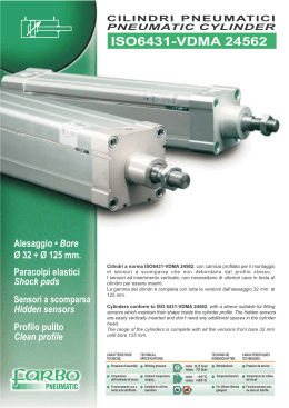
CILINDRI A NORMA ISO 6432 Ø8 ÷ Ø25 mm
CYLINDERS STANDARD ISO 6432 Ø8 ÷ Ø25 mm
CILINDRI TONDI Ø32 ÷ Ø63 mm
ROUND CYLINDERS Ø32 ÷ Ø63 mm
CILINDRI TONDI SERIE ED Ø32 ÷ Ø100 mm
ROUND CYLINDERS SERIE ED Ø32 ÷ Ø100 mm
Cat. n° M 0 1 0 8
GUIDA ALLA SCELTA DEL CILINDRO - CHOOSING A CYLINDER
Cilindri a norma ISO 6432 serie BAC - BAM - BAS / Cylinders standard ISO serie BAC - BAM - BAS
Pagina - Page
4
Alesaggi: Ø8, 10, 12, 16, 20, 25 mm.
Esecuzioni: a doppio e a semplice effetto, ammortizzati,
magnetici e non, con stelo passante.
Fissaggi secondo normativa ISO 6432.
Bore: Ø8, 10, 12, 16, 20, 25 mm.
Available versions: double and single-acting, cushioned,
magnetic or no-magnetic, through rod cylinder version.
Cylinder fixing ISO 6432 standard.
Cilindri tondi serie BAC - BAM - BAS / Round cylinders serie BAC - BAM - BAS
Pagina - Page
15
Alesaggi: Ø32, 40, 50, 63 mm.
Esecuzioni: a doppio e a semplice effetto, ammortizzati,
magnetici e non, con stelo passante.
Bore: Ø32, 40, 50, 63 mm.
Available versions: double and single-acting, cushioned,
magnetic or no-magnetic, through rod cylinder version.
Cilindri tondi serie ED / Round cylinders, serie ED
Pagina - Page
21
Alesaggi: Ø32, 40, 50, 63, 80, 100 mm.
Esecuzioni: a doppio effetto ammortizzato, magnetici
e non magnetici.
Bore: Ø32, 40, 50, 63, 80, 100 mm.
Available versions: double acting cushioned cylinder,
magnetic or no-magnetic.
2
INDICE - INDEX
CILINDRI TONDI Ø8 ÷ Ø25
ROUND CYLINDERS Ø8 ÷ Ø25
Informazioni tecniche
Forze teoriche
Dimensioni di ingombro
Codici di ordinazione cilindri
Esecuzioni speciali
Utilizzo di guide lineari
Fissaggi dei cilindri
Sensori magnetici
Technical information
Theoretical thrusts
Overall dimensions
Cylinders order code
Special versions
Application with guides units
Cylinder fixing
Magnetic switches
CILINDRI TONDI Ø32 ÷ Ø63
ROUND CYLINDERS Ø32 ÷ Ø63
Informazioni tecniche
Forze teoriche
Dimensioni di ingombro
Codici di ordinazione cilindri
Esecuzioni speciali
Fissaggi dei cilindri
Sensori magnetici
Technical information
Theoretical thrusts
Overall dimensions
Cylinders order code
Special versions
Cylinder fixing
Magnetic switches
CILINDRI TONDI SERIE ED
ROUND CYLINDERS ED SERIE
Informazioni tecniche
Forze teoriche
Dimensioni di ingombro
Codici di ordinazione cilindri
Fissaggi dei cilindri
Sensori magnetici
Technical information
Theoretical thrusts
Overall dimensions
Cylinders order code
Cylinder fixing
Magnetic switches
Pagina - Page
4
6
7
8
9
10
11
12
13
Pagina - Page
15
16
17
18
18
19
19
20
Pagina - Page
22
23
24
24
25
26
Le informazioni tecniche di questo catalogo sono soggette a variazioni senza preavviso.
The technical information presented in this catalogue could be subject to variations without notice.
3
21
CILINDRI A NORMA ISO 6432 - CYLINDER STANDARD ISO 6432
CARATTERISTICHE TECNICHE CILINDRI TONDI Ø8 ÷ Ø25
I cilindri pneumatici AIRON della serie BA dal Ø8 al Ø25 mm sono realizzati secondo le specifiche dimensionali contenute nella norma ISO 6432.
La serie BA viene realizzata nella versione base BAS, nella versione con pistone magnetico BAM e in quella
con pistone magnetico con ammortizzatori regolabili di fine corsa BAC.
Sono inoltre disponibili la serie TA che pur essendo derivata dalla serie BA è più compatta in quanto è priva
della cerniera posteriore; anche la serie TA può essere realizzata nella versione base TAS, nella versione
magnetica TAM e in quella con pistone magnetico e ammortizzatori regolabili di fine corsa TAC.
La serie SA anch’essa derivata dalla BA rispetto alla quale è più compatta, si differenzia da questa per la
testata posteriore che è senza cerniera e la connessione è eseguita in asse con lo stelo.
La serie SA può essere fornita nella versione base SAS o nella versione magnetica SAM.
Tutte le serie possono essere realizzate con numerose varianti ad esecuzioni speciali, che unitamente alla
completa gamma di accessori per il fissaggio del cilindro e ai diversi modelli di sensori magnetici offrono al
Cliente le più ampie possibilità di applicazione.
I principi progettuali seguiti nella realizzazione di questi cilindri, sono quelli dell’affidabilità, della robustezza
pur mantenendo un peso contenuto, della facilità di manutenzione e della gradevolezza estetica.
Infatti le testate (1-2) in alluminio lavorato alle macchine utensili e successivamente anodizzate,
vengono fissate alla camicia anch’essa in alluminio anodizzato per mezzo di un
accoppiamento filettato che permette in caso di necessità una agevole sostituzione
delle guarnizioni (4-5-6-7) senza dover sostituire il cilindro.
Le guarnizioni di tenuta pistone-camicia (5) sono del tipo a “labbro arrotondato” per
diminuire gli attriti e consentire basse velocità di traslazione senza incorrere in
fenomeni di stick-slip.
In tutte le versioni sono presenti degli smorzatori d’urto meccanici in gomma
nitrilica (5-8) che assorbendo parte dell’energia cinetica posseduta dal
carico limitano la rumorosità globale della macchina.
In fase di montaggio del cilindro le guarnizioni vengono
lubrificate con un grasso dalle elevate caratteristiche di
adesione superficiale che permette al cilindro di
lavorare anche con aria non lubrificata.
Infine ogni cilindro viene sottoposto
ad un controllo funzionale a garanzia
della massima affidabilità.
5
7
3
6
BAC ...
1
4
4
8
ROUND CYLINDERS OPERATING FEATURES Ø8 ÷ Ø25
AIRON pneumatic cylinders BA series from Ø8 to Ø25 mm are made in strict compliance with
dimensional specifications contained in ISO 6432.
BA cylinders come in a range of versions: the standard BAS version, the BAM version with magnetic
piston and the BAC version with magnetic piston with adjustable pneumatic cushioning.
The following are also available: - the TA series which, although an
off-shoot of the BA series, is more compact as it does not
have the rear hinge; available in the standard TAS version, the
magnetic TAM version and the TAC version with magnetic
piston and adjustable pneumatic cushioning.
- the SA series, again a derivative of the BA series and
again more compact; differs from the latter by way of
the hingeless rear end cap and in-axis ports. The SA
series includes a standard SAS version and a magnetic
SAM version.
Each series also includes numerous specialized versions,
thus offering the customer, together with the comprehensive
range of cylinder fixing accessories and the various magnetic
switches, a wide range of application possibilities.
The key features of these cylinders are reliability, a robust yet
lightweight structure, ease of maintenance and an attractive design. For
example, the aluminium covers, (1-2), machined and then anodized, are fixed to
the barrel (also in aluminium) by way of a threaded coupling which, when necessary,
allow easy replacement of the seals (4-5-6-7) avoiding to replace the cylinder.
The piston-liner gaskets (5) are of the "rounded lip" type which reduce friction and allow low
moving speeds without any stick-slip problems arising.
Mechanical impact absorbers in nitrile rubber (5-8) are fitted on all versions: these absorb a part of
the kinetic energy of the load and thus limit overall machine noise levels.
When assembling the cylinder, seals are lubricated with a highly surface-adhesive grease that allows
the cylinder to run even where the air is not lubricated.
Finally, every cylinder is put through
comprehensive testing to ensure
maximum reliability.
2
6
7
BAM ...
BAS ...
5
Informazioni tecniche - Technical information
Fluido - Fluid:
aria filtrata 40 μm lubrificata o non lubrificata (se lubrificata usare olio per circuiti pneumatici).
filtered air 40 μm lubricated or not lubricated ( when lubricated use oil for pneumatic circuits).
Temperatura fluido ed ambiente - Fluid and room temperature: -10/+80 °C
(consultare la tabella varianti dei cilindri e temperature di utilizzo dei finecorsa).
(consult the variants tables of cylinders and the referring temperatures of magnetic switch).
Pressione di esercizio - Working pressure: 1 ÷ 10 bar
Velocità massima - Maximum speed: 1 m/s
Lunghezza di ammortizzo - Effective cushioning length
Alesaggio - Bore (mm)
16
20
25
Lunghezza - Lenght (mm)
13
16
19
Corsa espressa in mm nella quale agisce effettivamente l’ammortizzo pneumatico.
Limit stroke expressed in mm during which the pneumatic cushioning really works.
Energia ammortizzabile - Max cushioning kinetic energy
Alesaggio - Bore (mm)
8
10
12
16
20
25
*Energia - Energy ( J )
0,02
0,03
0,06
0,8
1,1
1,6
*: Energia massima assorbibile dall’ammortizzo pneumatico (considerare la massima velocità di 1 m/s) - Dati validi solo per
versione BAC. Per BAS e BAM moltiplicare i valori in tabella per 0,15.
Max absorbing energy of pneumatic cushioning (consider the max speed of 1 m/s) - Data valid for versions BAC only.
For BAS and BAM multiply the values in table 5 by 0.15.
Masse dei cilindri - Inertial mass of cylinders
Alesaggio - Bore (mm)
8
10
12
16
20
25
Mb - Mb ( g )
34
40
80
107
200
210
Mu - Mu ( g )
0,6
0,3
0,4
0,5
0,8
1,9
Per il calcolo della massa dei cilindri ISO 6432 si utilizza la seguente formula:
To evaluate the inertial mass of cylinders ISO 6432 please use the following formula:
Mt
= Massa totale (g) - total mass
Mb
= Massa cilindro corsa 0 (g) - Cylinder mass stroke 0
Mu
= Massa per millimetro di corsa (g / mm) -Mass per millimeter of stroke
C
= Corsa del cilindro (mm) - Stroke of cylinder
Mt = Mb + (Mu•C)
NB: Le masse dei cilindri a corsa zero indicate in tabella fanno riferimento alla versione BAC; per le versioni magnetiche e non
magnetiche la massa si ottiene moltiplicando il valore in tabella per i rispettivi coefficienti 0,95 e 0,9.
NB: Zero-stroke cylinder masses given in the table refer to the BAC version. For magnetic and non-magnetic versions consider the Mb
correction coefficients to be 0.95 and 0.9 respectively.
Consumo d'aria - Air consumption
La determinazione del consumo di aria libera del cilindro espresso in Nl / min può essere fatto utilizzando la seguente formula:
To determine the free air consumption, expressed in NI / min, it can be used the following formula:
Q =
6
A•2C•n•(p+1)
1000
Q
A
C
n
p
=
=
=
=
=
Consumo di aria (Nl/min) - Air consumption
Area di spinta (cm2: tab. 4) - Thrust surface
Corsa del cilindro (cm) - Cylinder stroke
N° di cicli al minuto (x/min) - N° of cycles per minute
pressione relativa di lavoro (bar) - Working pressure
Forze teoriche - Theorical thrust
La tabella seguente permette di determinare le forze teoriche sviluppate dai cilindri sia in fase di uscita dello stelo che in fase di
rientro. Il valore indicato in grassetto rappresenta la forza in spinta mentre l’altro la forza in rientro; nel caso di cilindro a stelo passante si deve considerare il secondo valore sia in spinta che in tiro.
The following table permits to determine the theoretical thrusts developed by cylinders during both the rod outlet and its inlet. The value in bold
represents the thrust force while the others the tractive force; in the case of through rod cylinder the second value, both the thrust and the
tractive one, is to be considered.
Versione standard - standard version
Versione stelo passante - through rod (SP)
Tabella delle forze teoriche - Theorical thrust
Alesaggio - Bore (mm)
8
10
12
16
20
25
Superficie in spinta (cm2)
Surface to thrust
0,5
0,78
1,13
2,01
3,14
4,9
Superficie in trazione (cm2)
Surface to draught
0,37
0,66
0,85
1,73
2,64
4,12
Pressione - Pressure (Bar)
1
2
3
4
5
6
7
8
9
10
Forza - Thrust (N)
spinta - thrust
trazione - draught
spinta - thrust
trazione - draught
spinta - thrust
trazione - draught
spinta - thrust
trazione - draught
spinta - thrust
trazione - draught
spinta - thrust
trazione - draught
spinta - thrust
trazione - draught
spinta - thrust
5
3,7
10
7,4
15
11,1
20
14,8
25
18,5
30
22,2
35
25,9
40
7,8
6,6
15,6
13,2
23,4
19,8
31,2
26,4
39
33
46,8
39,6
54,6
46,2
62,4
11,3
8,5
22,6
17
39,9
25,5
45,2
34
56,5
42,5
67,8
51
79,1
59,5
90,4
20,1
17,03
40,2
34,6
60,3
51,9
80,4
69,2
100,5
86,5
120,6
103,8
140,7
121,1
160,8
31,4
26,4
68,8
52,8
94,2
79,2
25,6
105,6
157
132
188,4
158,4
219,8
184,8
251,2
49
41,2
98
82,4
147
123,6
196
164,8
245
206
294
247,2
343
288,4
392
trazione - draught
spinta - thrust
trazione - draught
spinta - thrust
trazione - draught
29,6
45
33,3
50
37
52,8
70,2
59,4
78
66
68
101,7
76,5
113
85
138,4
180,9
155,7
201
173
211,2
287
237,6
314
264
329,6
441
370,8
490
412
In generale la scelta del diametro ottimale del cilindro coinvolge un numero elevato di fattori i quali rendono laboriosa la soluzione.
L’esperienza pratica consiglia di dimensionare il cilindro in modo tale che la sua spinta (alla pressione di lavoro prescelta) sia compresa
Tra 1,5 e 2 volte il valore del carico da movimentare.
In general, to choose the optimum diameter of cylinder, a lot of different factors are to be considered, which could make the solution
difficult. According to our experience, we suggest to size up the cylinder till its thrust (to the chosen work pressure) is between 1.5 and 2 times
the value of load to move.
Materiali e dotazioni standard - Material and standard accessories
Testate: ........................ alluminio anodizzato
Stelo: ........................... acciaio C45 cromato
Camicia: ....................... alluminio estruso anodizzato (Ø 8 e 10 ottone)
Tenute: ........................ gomma nitrilica
Ammortizzo: ............... anteriore e posteriore pneumatico su BAC ,
smorzatori d'urto elastici su BAS e BAM
Covers: ........................ anodized aluminium
Piston rod: ................... C45 cromium plated steel
Barrel: ........................... extruded anodized aluminium (Ø8 and 10 brass)
Seals: .......................... nitrilic rubber
Cushioning: ................. pneumatic front and rear on BAC ,
elastic stopper on BAS and BAM
7
DIMENSIONI DI INGOMBRO - OVERALL DIMENSIONS
BAC .... ..
BAM .... ..
L1 + corsa - stroke
XC + corsa - stroke
AM
BAS .... ..
L2
L3 + corsa - stroke
KW
L
BE
KK
EW
KW1
SW
EE
L5
BE
L4
EE
CD
L10 + corsa - stroke
WH
D1
KV1
L4
D2
KV
L9 + corsa - stroke
Stelo semplice
Single rod
Il cilindro é fornito completo di un dado stelo e un dado testata
The cylinder is provided complete with one rod nut and one cover end nut
BAC .... .. SP
BAM .... .. SP
BAS .... .. SP
L9 + corsa - stroke
L1 + corsa - stroke
L6 + 2 x corsa - 2 x stroke
Stelo passante
Through rod
Il cilindro é fornito completo di 2 dadi stelo e 1 dado testata
The cylinder is provided complete with 2 rod nuts and 1 cover end nut
E
SAM .... ..
SAS .... ..
L7 + corsa - stroke
Coda tronca, alimentazione posteriore in asse
Compact cylinder, rear inlet port in line
Il cilindro é fornito completo di un dado stelo e un dado testata
The cylinder is provided complete with one rod nut and one cover end nut
TAC .... ..
TAM .... ..
TAS .... ..
L8 + corsa - stroke
Coda tronca, alimentazione perpendicolare all’asse
Compact cylinder, rear inlet port perpendicular to axis
Alesaggio
Bore (mm)
8
10
12
16
20
25
A AM
BE
CD ØD D1 D2 ØD6
EE
H9
4
4
6
6
8
10
12
12
16
16
20
22
M12x1,25
M12x1,25
M16x1,5
M16x1,5
M22x1,5
M22x1,5
4
4
6
6
8
8
EW
Il cilindro é fornito completo di un dado stelo e un dado testata
The cylinder is provided complete with one rod nut and one cover end nut
KK
L6 L7 L8 L9 L10 SW WH XC
L
L1
L2
L3
L4
16 8 6,6
16 8 6,6
18 9 8,2
22 11 10,2
28 14 12,2
34 17 15,5
12
14
16
20
24
29
M5
M5
M5
M5
G1/8
G1/8
8
8
12
12
16
16
M4
M4
M6
M6
M8
M10x1,25
19
19
24
24
32
32
6
6
9
9
12
12
70
74
87
93
111
117
21
21
27,5
27,5
32
35,5
32
34
45
45
52
54
12 11 74
12 11 74
15 14 94
15 14 100
19 17,5 116
20 18,5 125
7
7
10
10
13
17
7
7
8
8
10
10
2
2
4
4
5
6
Tolleranze nominali sulla corsa - nominal tollerances of stroke
Le tolleranze sulla corsa nominale sono di +1,5 -0 mm per tutte le corse.
Nominal tollerances of stroke are +1,5 -0 mm for all strokes.
8
L5
KV KV1 KW KW1
d13
53
53
68
71
86
91
58
58
72
78
92
97
42
46
50
56
68
69
42
46
44
51
59
65
5
5
7
8
16
16
22
22
24
28
64
64
75
82
95
104
CODICI DI ORDINAZIONE DEI CILINDRI - CYLINDERS ORDER CODES
ISO 6432
BA
SA
TA
Minicilindro ISO.
Mini cylinder ISO standard.
Minicilindro derivato dalla serie ISO, (ingombri ridotti). Alimentazione camera posteriore in asse.
Minicylinder derived from ISO series (compact). No rear hinge.
Minicilindro derivato dalla serie ISO, (ingombri ridotti). Senza cerniera posteriore.
Minicylinder derived from ISO series (compact). No rear hinge.
C
M
S
con ammortizzatori regolabili di fine corsa e magnetico (solo serie BA e TA, Ø16-20-25 mm).
with adjustable end-of-stroke shock absorbers and magnetic (BA and TA only, Ø16-20-25 mm).
magnetico.
magnetic.
non magnetico.
non magnetic.
alesaggio
bore
8; 10; 12;
16; 20;
25 mm.
Indicare in successione i codici
delle varianti o esecuzioni
speciali eventualmente richieste
(vedi pagina 10).
Corsa
Stroke (mm)
corse standard:
standard stroke:
Please indicate in sequence the
codes of variants or special
versions possibly requested
(see page 10).
10; 25; 40; 50; 75; 80; 100;
125; 150; 160; 200; 250;
300; 320; 400; 500 mm.
BA M 1 6 0 0 2 5 S F S E P
Varianti -Variants
Esecuzione:
Version:
Stelo:
Piston rod:
Tenuta stelo:
Rod seal:
Tenute interne:
Inside seals:
Ammortizzo
Pneumatico:
Pneumatic
Cushioning:
Stelo passante
Through rod
Acciaio INOX AISI 304
AISI 304 stainless steel
Acciaio INOX AISI 316
AISI 316 stainless steel
*) Elastomero fluorurato
Fluorine rubber
*) Elastomero fluorurato
Fluorine rubber
Solo anteriore
Front only
Solo posteriore
Rear only
Codice
Code
SP
A4
A6
VS
GV
AA
AP
BAC BAM BAS SAM SAS TAC TAM TAS
16 ÷ 25
8 ÷ 25
8 ÷ 25
8 ÷ 25
8 ÷ 25
16 ÷ 25
8 ÷ 25
8 ÷ 25
R
R
R
-
-
-
-
-
R
R
R
R
R
R
R
R
R
R
R
R
R
R
R
R
R
R
R
R
R
R
R
R
R
R
R
R
R
R
R
R
R
-
-
-
-
R
-
-
R
-
-
-
-
R
-
-
R = a richiesta -on request
- = non previsto -not available
)
=
Temperatura
max
150°C
- Max temperature 150°C
*
Come ordinare - Code example
Cilindro ISO 6432 con pistone magnetico e ammortizzatori
regolabili di fine corsa, alesaggio 16 mm e corsa 200 mm.
Cylinder ISO 6432 with magnetic piston and micrometric
pneumatic cushoning, bore Ø16 mm and stroke 200 mm.
BAC.16.0200
Cilindro ISO 6432 non magnetico, alesaggio 25 mm e corsa
25 mm, stelo filettato femmina, tenuta dello stelo in
elastomero fluorurato, semplice effetto molla posteriore.
Cylinder ISO 6432, not magnetic, bore 25 mm, stroke 25 mm,
female screw thread rod end, rod seal in fluorine rubber,
single acting rear spring.
BAS.25.0025.SF.VS.SEP
Codice kit guarnizioni - Seals kit code
Codice kit guarnizioni = SG + tipo cilindro + alesaggio + eventuali varianti.
Seals kit code = SG + cylinder type + bore + possible versions.
SG.BAS.12.GV
9
ESECUZIONI SPECIALI - SPECIAL VERSIONS
CODICE -CODE
DESCRIZIONE -DESCRIPTION
AM ..
COME ORDINARE -CODE EXAMPLE
Estremità dello stelo filetto maschio
con lunghezza a richiesta.
Dopo il codice del cilindro inserire la sigla “AM”
seguita dalla lunghezza della filettatura richiesta.
Screw tap rod end with length on
request.
After the cylinder code insert the initials “AM”
followed by the screw length to request.
AM
Es.: BAC.25.0200.AM60
WH ..
Sporgenza dello stelo a richiesta.
Rod protrusion on request.
Dopo il codice del cilindro inserire la sigla “WH”
seguita dalla lunghezza della sporgenza dello
stelo desiderata.
After the cylinder code insert the initials “WH”
followed by the required rod postrusion.
Es.: BAC.25.0200.WH80
WH
SF
Estremità dello stelo filettata femmina.
Dopo il codice del cilindro inserire la sigla “SF”.
Female screw thread rod end.
After the cylinder code insert the initials “SF”.
Alesaggio - bore
K
Z
WH
SD
12
16
20
25
(mm)
Z
K
M3
M3
M4
M5
6
6
8
10
Estremità dello stelo a disegno del
cliente.
Rod end according to the customer’ s
drawing.
Es.: BAC.25.0200.SF
Indicare il codice del cilindro, inserire la sigla
“SD” ed allegare all’ordine il disegno (o lo
schizzo) adeguatamente quotato.
Indicate the cylinder code, insert the initials “SD”
and enclose to the order the drawing (or sketch)
properly dimensioned.
Es.: BAC.25.0200.SD
SEA
Cilindro a semplice effetto con molla
anteriore, a riposo stelo rientrato.
Single acting cylinder front spring, inlet
rod at rest.
SEP
10
Cilindro a semplice effetto con molla
posteriore, a riposo stelo esteso.
Single acting cylinder rear spring, outlet
rod at rest.
Indicare il codice del cilindro e di seguito la sigla
“SEA” o “SEP”.
Per corse fino a 25 mm si conservano gli
ingombri del cilindro standard; per corse
superiori contattare l’ufficio tecnico-commerciale.
NB: solo versioni non ammortizzate.
Indicate the cylinder code followed by the initials
“SEA” or “SEP”.
For strokes of up to 25 mm standard cylinder
dimensions apply; for longer strokes contact out
technical/sales department.
NB: not cushioned version only.
Es.: BAM.25.0025.SEA
UTILIZZO DI GUIDE LINEARI - APPLICATION WITH GUIDES UNITS
I cilindri AIRON a norma ISO 6432 possono essere accoppiati alle unità di guida lineare serie
GH e GC per la movimentazione precisa di carichi elevati che possono produrre momenti
flettenti e torcenti non sopportabili dal cilindro stesso.
Le unità di guida, schematicamente rappresentate nei disegni a fianco sono disponibili nella
geometria a “C” con cuscinetti a strisciamento e nella geometria ad “H” con cuscinetti a
strisciamento o a ricircolo di sfere in relazione al tipo di applicazione.
Per ulteriori informazioni consultare il catalogo “Unità di Guida”.
ISO 6432 compliant AIRON cylinders can be coupled to the linear guide units of the GH and GC
series: these allow the user to effect precision handling of heavy loads which might produce flexing
or twisting moments that the cylinder itself is unable to support.
The linear guide units, illustrated in the drawings on the side, are available with C-type geometry
with piston bearings or H-type geometry with ball bearings depending on the type of application.
For further information consult the "Guide Unit" catalogue.
FISSAGGI CILINDRI - CYLINDER FIXING
I fissaggi permettono un rapido collegamento del cilindro alla macchina. Oltre a quelli previsti dalla normativa ISO vengono inseriti altri
modelli che aumentano le possibilità di applicazione del cilindro stesso.
I fissaggi a controcerniera, piedino e flangia sono realizzati in acciaio Fe 370 zincato.
The fittings allow for quick connection of the cylinder to the machine.
In addition to those models which comply with ISO standards there are others which increase the cylinder application range even further.
The hinge foot and flange fixings are all made of Fe 370 galvanized steel.
CODICI DI ORDINAZIONE FISSAGGI - FIXING ORDER CODE
Fissaggi al cilindro - Cylinder fixing. (CC; PB; FV; DT)
Fissaggi allo stelo - Piston rod fixing (FF; SA; SS; DS).
CC 2 5
Tipo di fissaggio
Fixing type
FF
Alesaggio cilindro.
Cylinder bore (mm)
Tipo di fissaggio
Fixing type
0 8
Ø filettatura dello stelo
Ø Thread piston rod (mm).
Punto di riferimento delle quote di ingombro - Reference of overall dimensions
G1
XC + corsa - stroke
XC
+C
OR
E
SA
-ST
RO
H
KE
G3
Le quote di ingombro del cilindro completo di fissaggio riportate nelle pagine seguenti (XC,
XA, W) fanno riferimento alla battuta della parte filettata sullo stelo.
H2
FB
G2
The cylinder dimensions complete with fixing quoted in the following pages (XC,
XA, W) are referring to the end part of the threaded rod.
Masse dei fissaggi - Fixing mass
Masse dei fissaggi (g) - Fixing mass (g)
Alesaggio
Bore
CC ..
DS ..
DT ..
FF ..
FV ..
PB ..
SA ..
SS . .
8
10
12
16
20
25
20
20
36
36
78
78
0,5
0,5
1,5
1,5
4
8,5
10,5
10,5
20
20
42
42
5
5
20
20
46
90
12
12
26
26
50
50
20
20
40
40
90
90
25
25
60
220
20
20
25
25
46
75
11
CC - -
G1
CONTROCERNIERA
+C
OR
US
FEMALE HINGE
RO
KE
H
(with pin)
- Acciaio zincato
Galvanized steel
- Ø 8 ÷ 25 mm
G3
PIEDINO
PEDESTAL
R1
AO
AU
SA
H2
FB
AB
(completa di perno)
-ST
H1
E
SA
NH
XC
PB - - - Ref. ISO MS3
- Acciaio zincato
Galvanized steel
- Ø 8 ÷ 25 mm
+C
OR
SA
-ST
RO
XA
+ C KE
OR
SA
-ST
G2
XS
RO
TR
KE
ZF
+C
OR
FV - - -
SA
-ST
RO
KE
H3
FF - -
FLANGIA
FLANGE
W
FORCELLA FEMMINA
YOKE
B
- Acciaio zincato
Galvanized steel
- Ø 8 ÷ 25 mm
F1
- Ref. ISO MF8
- Acciaio zincato
Galvanized steel
- Ø 8 ÷ 25 mm
C
F
F1
F2
FB
UF
TF
A
UR
SA - -
CH
D
SNODO AUTOALLINEANTE
SELF-ALIGNING JOINT
L
- Acciaio zincato
Galvanized steel
- Ø 8 ÷ 25 mm
K
C2
C1
DT - -
KW
1
AB
AN
AO
AU
B
B1
BE
1
A
C
C1
C2
8
10
12
16
20
25
21
21
31
31
42
52
4,5
4,5
5,5
5,5
6,6
6,6
Alesaggio
Bore (mm)
H
H1
H2
H3
KK
K
KV KV1
KW KW1
L
NH
8
10
12
16
20
25
24
24
27
27
30
30
3
3
4
4
5
5
2,5
2,5
3
3
4
4
3
3
4
4
5
5
M4
M4
M6
M6
M8
M10x1,25
8
8
9
9
12
14
19
19
24
24
32
32
7
7
8
8
10
10
1
1
2
2
16
16
20
20
25
25
CH
D
E
F
F1
F2
FB
f8
5
5
7
7
8
8
11
11
14
14
17
17
8
8
12
12
16
20
35
35
57
71
M12x1,25
M12x1,25
M16x1,5
M16x1,5
M22x1,5
M22x1,5
7
7
10
10
13
17
- Acciaio zincato
Galvanized steel
- Ø 8 ÷ 25 mm
KV
Alesaggio
Bore (mm)
13
13
13
13
14
13
DADO PER STELO
ROD NUT
KK
- Acciaio zincato
Galvanized steel
- Ø 8 ÷ 25 mm
BE
KV
DS - -
KW
DADO PER TESTATA
COVER NUT
12
SNODO SFERICO
AUTOLUBRIFICANTE
SPHERIC SELFLUBRICATING ROD END
AN
- Acciaio zincato
Galvanized steel
- Ø 12 ÷ 25 mm
KK
SW
B1
SS - -
16
16
24
24
32
40
3
3
4
4
5
6
10
10
20
20
27
27
30
30
36
43
7
7
11
19
12
12
16
16
22
26
4,5
4,5
5,5
5,5
6,6
6,6
H9
H7
4
4
6
6
8
10
5
5
6
6
8
10
G2
G3
ØH
9
9
11
11
14
17
4
4
6
6
8
8
4
4
6
6
8
10
SA
SW
TF
TR
UF
UR US
W
ZF
XC
XS
10
64
10
68
12,5 82
12,5 88
20 108
20 109
5
5
7
12
30
30
40
40
50
50
25
25
32
32
40
40
40
40
53
53
66
66
22
22
30
30
40
40
13
13
18
18
19
23
61 69 58
65 73 62
76 86 75
82 92 82
97 109 95
103 115 104
24
24
32
32
36
40
R1
8
8
12
12
16
20
ØG ØG1 G1
35
35
42
42
54
54
5,5 12,5 20 24
5,5 12,5 20 24
12,5 15 25 14,5
12,5 15 25 14,5
16 20 32 19
16 20 32 32
XA
SENSORI MAGNETICI E STAFFE - MAGNETIC SWITCHES AND BRACKETS
Il sensore magnetico è un dispositivo elettronico che rileva la presenza di un campo magnetico. Collegato al cilindro magnetico, viene
prevalentemente utilizzato come interruttore di prossimità per aprire o chiudere un circuito elettrico.
La gamma di sensori che AIRON propone per i suoi cilindri magnetici si articola su tre circuiti elettrici e due tipi di connessione del cavo al corpo del
sensore.
Il sensore nella versione ampolla Reed può essere scelto con circuito a due fili oppure a tre fili permettendo quest’ultimo di effettuare collegamenti in
serie dei sensori stessi nei casi in cui siano necessari più consensi.
La versione elettronica (sensore magneto-resistivo) essendo priva di contatti elettrici ha i seguenti vantaggi rispetto all’ampolla Reed:
una durata superiore dell’ordine di 109 cicli contro i 107; tempi di chiusura ed apertura del circuito notevolmente più bassi, isteresi inferiore e possibilità
di utilizzare cavi più lunghi.
Il fissaggio dei sensori magnetici al cilindro avviene per mezzo di staffe in materiale plastico opportunamente sagomate e dotate di un pratico sistema
di bloccaggio che le rende insensibili alle vibrazioni e rapide da installare e posizionare.
The magnetic switch is an electronic device which reveals the presence of a magnetic field. It is connected to the magnetic cylinder
and it is mostly used as a proximity switch to open or to close an electric circuit.
The Reed switch is available with two leads circuit or with three leads. In the second one it is possible to carry out connections in series of the switches
if more cascade connections are requested.
The electronic version (magnetic-restive switch), as it has no electrical contacts, presents the following advantages in comparison with the Reed
switch: a longer life in order of 109 cycles compared with 107; remarkably lower open and closed circuit times, lower hysteresis and allowable to use
longer wires. The cylinder switches are fastened with plastic brackets properly shaped and provided with a practical clamping system which make
them insensitive to vibration and they can be quickly set up and doweled.
S03
Staffa in dotazione
al sensore
Bracket included
with sensor
SMT ...
FTT ..
SMP ...
FT ..
Fissaggi per sensori magnetici e dimensioni di ingombro - Brackets for magnetic switches and dimensions
SMP.2C
SMP.3C
SMP.EC
SMT.EC
SMT.ED
B
A
B
E
F
SMP.2D
SMP.3D
SMP.ED
D
SMT.3C
SMT.3D
G
SMT.2C
SMT.2D
Ø
C
A
C
F
B
FTT ..
A
Ø
D
F
FT ..
Codice
Code
Alesaggio
Bore (mm)
A
B
ØC
D
E
F
FTT.12
8
22
25
12
18
15
FTT.14
10
24
27
14
18
FTT.16
12
26
29
16
FTT.20
16
30
33
FTT.24
20
34
FTT.29
25
42
FTT.36
32
FTT.45
E
E
Codice
Code
Alesaggio
Bore (mm)
A
B
ØC
D
E
F
G
18
FT.12
8
8
17
12
2
9
4
13
16
18
FT.14
10
9
18
14
2
8
4
13
20
16
18
FT.16
12
10
20
16
2
7
4
13
20
22
20
18
FT.20
16
12
23
20
2
5
2
13
37
24
24
21
18
FT.24
20
14
25
24
2
3
1
13
39
29
26
24
18
FT.29
25
15,5
28,5
29
2
0
-1
13
45
48
36
29
29
18
FT.36
32
20
32
36
2
0
-4
13
40
55
57
45
36
33
18
FT.45
40
26
37
45
2
0
-2
13
FTT.55
50
66
70
55
47
41
18
FT.55
50
30
42
55
2
0
-1
13
FTT.68
63
79
83
68
50
44
18
63
Non disponibile - Not available
13
Informazioni tecniche - Technical information
Grado di protezione - protection class: IP 67 EN 60529
Temperatura di impiego - working temperature: -10/+80 °C
Materiale custodia - Housing material: PA (+G)
Cavo flessibile - Flexible cable: PVC Ø 3,5 mm, L = 2500 mm
CODICI DI ORDINAZIONE SENSORI - MAGNETIC SWITCHES ORDER CODES
CC.SMS.3
3 poli - 3 poles
SMT 3 C
CAVO L = 3 m CON CONNETTORE
(solo per sensore serie SMS)
LEAD L = 3 m WITH CONNECTOR
(only SMS magnetic switch series)
C Con connettore
With switch connector
Tipo di sensore magnetico
Magnetic switch type
2
SMP...
SMT...
3
E
diretto sul sensore
D Cavo
With direct connector
Tipo di circuito - Magnetic switch circuit type
Circuito con ampolla Reed normalmente aperta,
protetta da varistore contro le sovratensioni generate
all’apertura del circuito, e sistema di visualizzazione.
Circuito consigliato per la maggior parte delle
applicazioni.
Circuit with Reed switch normally open protected by a
varistor against overvoltage caused when switching off, with
indicator. Recommended circuit for most applications.
Dati - Data
Tensione AC - Voltage AC
Tensione DC - Voltage DC
Corrente a 25°C - Current at 25°C
Pot. con carico induttivo -Power (inductive)
Tempo inserzione - On time
Tempo disinserzione - Off time
Vita elettrica - Electric life
Resistenza di contatto - Contact resistance
SMP
3-115 V
3-115 V
0,3 A
10 VA
0,6 ms
0,1 ms
107
0,1 Ω
SMT
5-120 V
5-120 V
0,1 A
3 VA
0,5 ms
0,1 ms
107
0,1 Ω
SM. . 2.
Circuito con ampolla Reed normalmente aperta e sistema
di visualizzazione autoalimentato mediante un terzo filo
(nero). Indicato per il collegamento di più sensori in serie
in quanto elimina la caduta di tensione.
Circuit with Reed switch normally open and indicator supplied
by a third lead (black). Suitable for supplyng several switches
in series as it eliminates the voltage drop.
Dati - Data
Tensione DC - Voltage DC
Corrente a 25°C - Current at 25°C
Pot. con carico induttivo-Power (inductive)
Tempo inserzione - On time
Tempo disinserzione - Off time
Vita elettrica - Electric life
Resistenza di contatto-Contact resistance
SMP
24 V
1A
10 VA
0,5 ms
0,1 ms
107
0,1 Ω
SMT
10-30 V
0,1 A
3 VA
0,5 ms
0,1 ms
107
0,1 Ω
SM. . 3.
Circuito con effetto Hall normalmente aperto con uscita
PNP. Protetto contro l’inversione di polarità e contro onde
di sovratensione.
Circuit with Hall-effect switch normally open with
outlet PNP. Protection against overvoltages and reverse of
polarity.
Dati - Data
Tensione DC - Voltage DC
Corrente a 25°C - Current at 25°C
Potenza massima - Power (inductive)
Tempo inserzione - On time
Tempo disinserzione - Off time
Vita elettrica - Electric life
Caduta di tensione diretta - On voltage drop
SMP
6-30 V
0,25 A
6 VA
0,8 μs
0,3 μs
109
0,7 V
SMT
10-30 V
0,1 A
3 VA
0,8 μs
0,3 μs
109
2V
SM. . E.
Per dettagli tecnici consultare il catalogo sensori (SMT....). - For technical features see sensor catalogue (SMT....).
14
CILINDRI TONDI Ø32 ÷ Ø63 mm - ROUND CYLINDERS, Ø32 ÷ Ø63 mm
La norma ISO 6432 stabilisce le specifiche dimensionali dei cilindri fino all’alesaggio 25 mm.
Nonostante ciò, al fine di offrire ai tecnici ulteriori possibilità nella scelta del cilindro,
AIRON ha ampliato la gamma della serie BA introducendo gli alesaggi 32, 40, 50 e 63 mm,
realizzandoli con una forma “tonda” che li rende poco ingombranti e particolarmente “puliti”.
Proposti nei modelli base BAS, con pistone magnetico BAM,
con pistone magnetico e gli ammortizzatori regolabili di fine corsa BAC,
tutti i modelli hanno in comune gli ingombri e gli stessi principi progettuali
quali la robustezza, l’affidabilità e la gradevolezza estetica.
BAC ...
BAM ...
Standard ISO 6432 establishes the specific dimensions
of the cylinders up to the 25 mm bore.
Despite this,
in order to offer technicians further possibilities in the choice of cylinder,
AIRON has widened the range of the BA series introducing the 32, 40, 50 and 63 mm bore, producing
them in a “round form” that makes them less awkward and particularly “clean profile”.
Proposed in the basic BAS version, with a magnetic BAM piston, with a magnetic piston and the
adjustable pneumatic cushioning BAC, all the models have the obstacles in common and the
same design principals of strength, reliability and pleasant appearance.
15
Informazioni tecniche - Technical information
Fluido - Fluid:
aria filtrata 40 μm lubrificata o non lubrificata (se lubrificata usare olio per circuiti pneumatici).
filtered air 40 μm lubricated or not lubricated ( when lubricated use oil for pneumatic circuits).
Temperatura fluido ed ambiente - Fluid and room temperature: -10/+80 °C
(consultare la tabella varianti dei cilindri e temperature di utilizzo dei finecorsa).
(consult the variants tables of cylinders and the referring temperatures of magnetic switch).
Pressione di esercizio - Working pressure: 1 ÷ 10 bar
Velocità massima - Maximum speed: 1 m/s
Lunghezza di ammortizzo - Effective cushioning length
Alesaggio - Bore (mm)
32
40
50
63
Lunghezza - Lenght (mm)
20
21
22
23
Corsa espressa in mm nella quale agisce effettivamente l’ammortizzo pneumatico.
Limit stroke expressed in mm during which the pneumatic cushioning really works.
Energia ammortizzabile - Max cushioning kinetic energy
Alesaggio - Bore (mm)
32
40
50
63
*Energia - Energy ( J )
1,9
2,2
4
6
*: Energia massima assorbibile dall’ammortizzo pneumatico (considerare la massima velocità di 1 m/s) - Dati validi solo per
versione BAC. Per BAS e BAM moltiplicare i valori in tabella per 0,15.
Max absorbing energy of pneumatic cushioning (consider the max speed of 1 m/s) - Data valid for versions BAC only.
For BAS and BAM multiply the values in table 5 by 0.15.
Masse dei cilindri - Inertial mass of cylinders
Alesaggio - Bore (mm)
32
40
50
63
Mb - Mb ( g )
540
690
1050
1500
Mu - Mu ( g )
2,3
3,2
4,8
5,1
Per il calcolo della massa dei cilindri tondi si utilizza la seguente formula:
To evaluate the inertial mass of rounded cylinders please use the following formula:
Mt
= Massa totale (g) - total mass
Mb
= Massa cilindro corsa 0 (g) - Cylinder mass stroke 0
Mu
= Massa per millimetro di corsa (g / mm) -Mass per millimeter of stroke
C
= Corsa del cilindro (mm) - Stroke of cylinder
Mt = Mb + (Mu•C)
NB: Le masse dei cilindri a corsa zero indicate in tabella fanno riferimento alla versione BAC; per le versioni magnetiche e non
magnetiche la massa si ottiene moltiplicando il valore in tabella per i rispettivi coefficienti 0,95 e 0,9.
NB: Zero-stroke cylinder masses given in the table refer to the BAC version. For magnetic and non-magnetic versions consider the Mb
correction coefficients to be 0.95 and 0.9 respectively.
Consumo d'aria - Air consumption
La determinazione del consumo di aria libera del cilindro espresso in Nl / min può essere fatto utilizzando la formula descritta a
pagina 6.
To determine the free air consumption, expressed in NI / min, it can be used the formula at page 6.
16
Forze teoriche - Theorical thrust
La tabella seguente permette di determinare le forze teoriche sviluppate dai cilindri sia in fase di uscita dello stelo che in fase di
rientro. Il valore indicato in grassetto rappresenta la forza in spinta mentre l’altro la forza in rientro; nel caso di cilindro a stelo passante si deve considerare il secondo valore sia in spinta che in tiro.
The following table permits to determine the theoretical thrusts developed by cylinders during both the rod outlet and its inlet. The value in bold
represents the thrust force while the others the tractive force; in the case of through rod cylinder the second value, both the thrust and the
tractive one, is to be considered.
Tabella delle forze teoriche - Theorical thrust
Alesaggio - Bore (mm)
32
40
50
63
Superficie in spinta (cm2)
Surface to thrust
8,04
12,56
19,63
31,16
Superficie in trazione (cm2)
Surface to draught
6,91
10,55
16,50
28,00
196
176
393
352
588
528
785
704
981
880
1178
1056
1373
1232
1570
1408
1765
1584
1963
1760
311
292
623
584
934
876
1246
1168
1558
1460
1869
1752
2181
2044
2493
2336
2804
2628
3116
2920
Pressione - Pressure (Bar)
Forza - Thrust (N)
spinta - thrust
trazione - draught
spinta - thrust
trazione - draught
spinta - thrust
trazione - draught
spinta - thrust
trazione - draught
spinta - thrust
trazione - draught
spinta - thrust
trazione - draught
spinta - thrust
trazione - draught
spinta - thrust
trazione - draught
spinta - thrust
trazione - draught
spinta - thrust
trazione - draught
1
2
3
4
5
6
7
8
9
10
80
69
160
140
240
207
322
276
402
345
482
414
563
484
643
553
724
622
804
691
125
114
251
228
376
342
502
456
628
570
754
684
879
798
1005
912
1130
1026
1256
1140
In generale la scelta del diametro ottimale del cilindro coinvolge un numero elevato di fattori i quali rendono laboriosa la soluzione.
L’esperienza pratica consiglia di dimensionare il cilindro in modo tale che la sua spinta (alla pressione di lavoro prescelta) sia compresa
Tra 1,5 e 2 volte il valore del carico da movimentare.
In general, to choose the optimum diameter of cylinder, a lot of different factors are to be considered, which could make the solution
difficult. According to our experience, we suggest to size up the cylinder till its thrust (to the chosen work pressure) is between 1.5 and 2 times
the value of load to move.
Forze teoriche molle cilindri tondi (N) - Theoretical thrusts of round cylinders springs (N)
Corsa - Stroke
(mm)
5
10
20
30
40
50
32
min - max
48,5
46,5
42,5
38,5
34,5
30,5
-
50
50
50
50
50
50
Alesaggio - Bore (mm)
40
50
min - max
73
71
67
63
59
54
-
75
75
75
75
75
75
63
min - max
min - max
73,5
72
69
66
63
60
73,5
72
69
66
63
60
-
75
75
75
75
75
75
-
75
75
75
75
75
75
Semplice effetto stelo retratto
Single-acting retract piston-rod
Semplice effetto stelo esteso
Single-acting extended piston-rod
Materiali e dotazioni standard - Material and standard accessories
Testate: ........................ alluminio anodizzato
Stelo: ........................... acciaio C45 cromato
Camicia: ....................... tubo alluminio anodizzato
Tenute: ........................ stelo in poliuretano, altre in gomma NBR
Ammortizzo: ............... anteriore e posteriore
Covers: ........................ anodized aluminium
Piston rod: ................... C45 cromium plated steel
Barrel: ........................... aluminium tube anodized
Seals: .......................... piston rod of poliurethane, others NBR
Cushioning: ................. front and rear
17
DIMENSIONI DI INGOMBRO - OVERALL DIMENSIONS
BAC .... ..
BAM .... ..
B1 + corsa - stroke
B + corsa - stroke
WH
M
L
I
D
I
H
KK
H
Stelo semplice
Single rod
AM
E
N
O
SW
BAS .... ..
N
Il cilindro é fornito
completo di un dado stelo
e un dado testata.
The cylinder is provided
complete with one rod nut
and one cover end nut.
A1 + corsa - stroke
BAC .... .. SP
BAM .... .. SP
BAS .... .. SP
A1 + corsa - stroke
L1 + corsa - stroke
L2 + 2 x corsa - stroke
Stelo passante
Through rod
Il cilindro é fornito completo di due dadi stelo e un dado testata
The cylinder is provided complete with two rod nuts and one cover end nut
Alesaggio
Bore (mm)
ØA
A1
B
B1
WH
D
E
AM
KK
H
I
L
L1
L2
M
N
O
32
40
50
63
12
16
20
20
96
113
120
124
78
89
96
98
134
158
170
174
38
45
50
50
14
16
18
18
30
35
38
38
20
24
32
32
M10x1,25
M12x1,25
M16x1,5
M16x1,5
M30x1,5
M38x1,5
M45x1,5
M45x1,5
G1/8
G1/4
G1/4
G3/8
47
57
62
63
164
193
208
212
172
203
220
224
36,8
44,8
55,8
68,8
M8x1
M10x1
M12x1,5
M14x1,5
38
46
57
70
Tolleranze nominali sulla corsa - nominal tollerances of stroke
Le tolleranze sulla corsa nominale sono di +1,5 -0 mm per tutte le corse.
Nominal tollerances of stroke are +1,5 -0 mm for all strokes.
CODICI DI ORDINAZIONE DEI CILINDRI - CYLINDERS ORDER CODES
BA
Cilindri tondi.
Round cylinder.
C
M
S
corsa stroke
ammortizzato magnetico.
magnetic absorbers.
magnetico.
magnetic.
non magnetico.
non magnetic.
corse standard:
standard stroke:
25; 40; 50; 75; 80;
100; 125; 150; 160;
200; 250; 300; 320;
400; 500 mm.
Alesaggio
Bore
32; 40; 50;
63 mm.
Indicare in successione i
codici delle varianti o
esecuzioni
speciali
eventualmente richieste
(vedi pagina 10).
Please indicate in sequence
the codes of variants or
special versions possibly
requested (see page 10).
BA M 3 2 5 0 S F SEP
Varianti -Variants
Semplice effetto molla anteriore
Semplice effetto molla anteriore
Esecuzione:
Version:
Come ordinare - Code example
Cilindro magnetico, alesaggio
Ø40 mm e corsa 50 mm.
Magnetic cylinder, bore Ø40 mm
and stroke 50 mm.
BAM.040.50
Codice kit guarnizioni = SG • BAM • alesaggio.
Seals kit code = SG • BAM • bore.
SG.BAM.040
18
Codice
Code
SEA
SEP
SP
A4
A6
VS
GV
Semplice effetto molla posteriore
Semplice effetto molla posteriore
Stelo passante
Through rod
Acciaio INOX AISI 304
AISI 304 stainless steel
Stelo:
Piston rod:
Acciaio INOX AISI 316
AISI 316 stainless steel
Tenuta stelo:
*) Elastomero fluorurato
Rod seal:
Fluorine rubber
Tenute interne:
*) Elastomero fluorurato
Inside seals:
Fluorine rubber
*) = Temperatura max 150°C - Max temperature 150°C
ESECUZIONI SPECIALI - SPECIAL VERSIONS
COME ORDINARE -CODE EXAMPLE
Dopo il codice del cilindro inserire la sigla “AM”
seguita dalla lunghezza della filettatura da richiedere.
After the cylinder code insert the initials “AM”
followed by the screw length to request.
Es.: BAC.32.0200.AM60
DESCRIZIONE -DESCRIPTION
AM
Sporgenza dello stelo a richiesta.
Rod protrusion on request.
Dopo il codice del cilindro inserire la sigla “SF”.
After the cylinder code insert the initials “SF”.
Es.: BAC.32.0200.SF
Estremità dello stelo filettata femmina.
Female screw thread rod end.
WH ..
WH
Alesaggio - bore
(mm)
Z
K
M6
M6
M10
M10
12
12
14
14
SF
K
WH
Z
32
40
50
63
Indicare il codice del cilindro e di seguito la sigla
“SEA” o “SEP”.
Gli ingombri delle versioni a semplice effetto
“SEA” o “SEP” sono le stesse delle relative
versioni a doppio effetto.
NB: solo versioni non ammortizzate.
Indicate the cylinder code followed by the initials
“SEA” or “SEP”.
Overall dimension of single acting version “SEA” or
“SEP” are the same of double acting version.
NB: not cushioned version only.
Es.: BAM.32.0200.SEA
AM ..
Estremità dello stelo filetto maschio con
lunghezza a richiesta.
Screw tap rod end with length on request.
Dopo il codice del cilindro inserire la sigla “WH”
seguita dalla lunghezza della sporgenza dello
stelo desiderata.
After the cylinder code insert the initials “WH”
followed by the required rod postrusion.
Es.: BAC.32.0200.WH80
Indicare il codice del cilindro, inserire la sigla “SD”
ed allegare all’ordine il disegno (o lo schizzo)
adeguatamente quotato.
Indicate the cylinder code, insert the initials “SD” and
enclose to the order the drawing (or sketch) properly
dimensioned.
Es.: BAC.32.0200.SD
CODICE -CODE
Estremità dello stelo a disegno del cliente.
Rod end according to the customer’s drawing.
SD
SEA
Cilindro a semplice effetto con molla
anteriore, a riposo stelo rientrato.
Single acting cylinder front spring,
inlet rod at rest.
Cilindro a semplice effetto con molla
posteriore, a riposo stelo esteso.
Single acting cylinder rear spring,
outlet rod at rest.
SEP
FISSAGGI CILINDRI - CYLINDER FIXING
I fissaggi cilindri permettono un rapido collegamento del cilindro alla macchina. Sono realizzati in acciaio zincato.
The fittings allow for quick connection of the cylinder to the machine. They are made in galvanized steel.
CODICI DI ORDINAZIONE FISSAGGI - FIXING ORDER CODE
Fissaggi allo stelo - Piston rod fixing
(FF; SA; SS; FA; GCP).
Masse dei fissaggi - Fixing mass
Alesaggio
Bore
32
40
50
63
Masse dei fissaggi - Fixing mass (g)
KK
FF 10 (90) SA 10 (220) DS 10 (9) SS 10 (75)
FF 12 (153) SA 12 (230) DS 12 (12) SS 12 (112)
FA 10 (220) GCP 10 (102)
FA 12 (442) GCP 12 (160)
M10 x 1,25
M12 x 1,25
FF 16 (317) SA 16 (660) DS 16 (20) SS 16 (220)
FA 16 (874) GCP 16 (200)
M16 X 1,5
FF
Tipo di fissaggio
Fixing type
1 6
Ø filettatura dello stelo
Ø Thread piston rod (mm).
19
PL - - -
CONTROCERNIERA (completa di perni)
FEMALE HINGE (with pins)
CZ
FLANGIA PIEDINO
PEDESTAL
- Acciaio zincato
Galvanized steel
- Ø 32 ÷ 63 mm
AB
XC
(+
co
- Acciaio zincato
Galvanized steel
- Ø 32 ÷ 50 mm
N2
- Acciaio zincato
Galvanized steel
- Ø 32 ÷ 63 mm
A1
FP - S
PERNO LATERALE
LATERAL PIN
CC - -
T1
rsa
)
XB
rsa
CR
)
P1
CT
CE
ZR
+C
XB
SA
-S
TR
OK
E
CU
P2
U
CH
LT
CG
OR
R
co
Q
(+
Q1
XC
M1
W
CO
Alesaggio
Bore (mm)
XB
XC
ØA
A1
AB
CE
CG C H CO
CR
CT
CU
CZ
LT
M1
N2
P1
P2
Q
Q1
R
S
T1
U
W
ZR
32
47
125
10
53
7
8
40
35
4
24
20
50,1
60,8
4
66
49
21
52
28
14
28
30
7
14
4
124
40
57
146
12
64
9
10
50
40
3
30
28
60,1
74
5
80
58
30
60
30
18
33
38
9
20
5
153
50
62
158
14
78
9
10
54
45
4
34
36
74,1
90,6
6
90
70
30
70
40
20
40
45
9
20
6
160
63
63
161
16
95
9
10
65
50
1
35
42
88,1
106,8
6
-
-
-
-
-
-
-
-
-
-
-
-
FF - -
SA - -
SS - -
DS - -
FORCELLA FEMMINA
YOKE
SNODO AUTOALLINEANTE
SELF-ALIGNING JOINT
SNODO SFERICO AUTOLUBRIFICANTE
SPHERIC SELF-LUBRICATING ROD END
DADO PER STELO
ROD NUT
- Acciaio zincato
Galvanized steel
- Ø 32 ÷ 63 mm
- Acciaio zincato
Galvanized steel
- Ø 32 ÷ 63 mm
- Acciaio zincato
Galvanized steel
- Ø 32 ÷ 63 mm
- Acciaio zincato
Galvanized steel
- Ø 32 ÷ 63 mm
CH
B
D
SW
T
F
K
C2
F2
B1
1
CH
C1
2
F1
2
C
A
KK
F1
KK
AN
Alesaggio
Bore
A
32
51
13°
20
71
40
20
43
19
17
17
13
19
10
20
40
62
13°
24
75
48
24
50
19
19
19
15
22
12
24
50
82
15°
32
103
64
32
64
30
24
24
20
27
16
63
82
15°
32
103
64
32
64
30
24
24
20
27
16
AN
B
B1
C
C1
C2
CH
CH1
CH2
CH3
D
F
F1
F2
ØH
SW
T
K
KK
10
32
12
6
14
M10 x 1,25
12
32
12
7
16
M12 x 1,25
16
16
45
20
8
21
M16 x 1,5
16
16
45
20
8
21
M16 x 1,5
ØG
ØG1
H9
H7
25
10
29
12
32,5
38
32,5
38
B12
SENSORI MAGNETICI E STAFFE - MAGNETIC SWITCHES AND BRACKETS
SMT ...
Staffa in dotazione al sensore
Bracket included with sensor
S03
FTT ..
SMP ...
FT ..
Alesaggio - Bore (mm)
ØC
Codice
Code
32
40
50
63
36
45
55
68
FTT.36
FTT.45
FTT.55
FTT.68
Alesaggio - Bore (mm)
Per le caratteristiche tecniche, consultare pagina 13 e 14. - For technical features, see pages 13-14.
20
ØC
Codice
Code
32
40
50
63
36
45
55
-
FT.36
FT.45
FT.55
CILINDRI TONDI SERIE ED - ROUND CYLINDERS, SERIE ED
I cilindri pneumatici AIRON della serie ED trovano impiego soprattutto in quelle applicazioni dove l’ingombro del
cilindro è determinante per l’applicazione stessa. Infatti la superficie del cerchio che determina l’ingombro in pianta
del cilindro è maggiore solamente di qualche millimetro rispetto all’area del pistone che determina la forza del cilindro; mantenendo allo stesso tempo un alto livello di robustezza e di gradevolezza estetica.
La serie ED disponibile negli alesaggi 32 - 40 - 50 - 63 - 80 e 100 mm viene proposta nella versione base EDS che
prevede gli ammortizzatori regolabili di fine corsa e la versione EDM che in aggiunta al base ha la
predisposizione per l’utilizzo di sensori magnetici per il rilevamento della posizione del pistone; per entrambe
le versioni il tecnico può scegliere l’estremità dello stelo
filettato maschio o femmina.
EDM ...
EDS ...
The AIRON pneumatic cylinders of the ED series are used above-all in those applications
where the obstacle of the cylinder is determinant for the application itself.
In fact, the surface of the circle that determines the obstacle placed in the cylinder, is larger only
my a few millimeters compared to the area of the piston that determines
the strength of the cylinder; maintaining at the same time a high level of strength and pleasant appearance.
The ED series, available in the 32 - 40 - 50 - 63 - 80 and 100 mm bore, is proposed in the basic EDS version
that foresees adjustable pneumatic cushioning and the EDM version that at the basic version
has settings for the use of magnetic switches for showing the position of the piston; for both version
the technician must choose the threaded male or female piston-rod end.
21
Informazioni tecniche - Technical information
Fluido - Fluid:
aria filtrata 40 μm lubrificata o non lubrificata (se lubrificata usare olio per circuiti pneumatici).
filtered air 40 μm lubricated or not lubricated ( when lubricated use oil for pneumatic circuits).
Temperatura fluido ed ambiente - Fluid and room temperature: -10/+80 °C
(consultare la tabella varianti dei cilindri e temperature di utilizzo dei finecorsa).
(consult the variants tables of cylinders and the referring temperatures of magnetic switch).
Pressione di esercizio - Working pressure: 1 ÷ 10 bar
Velocità massima - Maximum speed: 1 m/s
Lunghezza di ammortizzo - Effective cushioning length
Alesaggio - Bore (mm)
32
40
50
63
80
100
Lunghezza - Lenght (mm)
20
21
22
23
27
27
Corsa espressa in mm nella quale agisce effettivamente l’ammortizzo pneumatico.
Limit stroke expressed in mm during which the pneumatic cushioning really works.
Energia ammortizzabile - Max cushioning kinetic energy
Alesaggio - Bore (mm)
*Energia - Energy ( J )
32
40
50
63
80
100
1,9
2,2
4
6
11
16
*: Energia massima assorbibile dall’ammortizzo pneumatico (considerare la massima velocità di 1 m/s) - Dati validi solo per
versione BAC. Per BAS e BAM moltiplicare i valori in tabella per 0,15.
Max absorbing energy of pneumatic cushioning (consider the max speed of 1 m/s) - Data valid for versions BAC only.
For BAS and BAM multiply the values in table 5 by 0.15.
Masse dei cilindri - Inertial mass of cylinders
Alesaggio - Bore (mm)
32
40
50
63
80
100
Mb
540
690
1050
1500
2400
3600
Mu
2,3
3,2
4,8
5,1
7,6
8,8
Per il calcolo della massa dei cilindri ISO 6432 si utilizza la seguente formula:
To evaluate the inertial mass of cylinders ISO 6432 please use the following formula:
Mt
= Massa totale (g) - total mass
Mb
= Massa cilindro corsa 0 (g) - Cylinder mass stroke 0
Mu
= Massa per millimetro di corsa (g / mm) -Mass per millimeter of stroke
C
= Corsa del cilindro (mm) - Stroke of cylinder
Mt = Mb + (Mu•C)
Consumo d'aria - Air consumption
La determinazione del consumo di aria libera del cilindro espresso in Nl / min può essere fatto utilizzando la formula descritta a
pagina 6.
To determine the free air consumption, expressed in NI / min, it can be used the formula at page 6.
22
Forze teoriche - Theorical thrust
La tabella seguente permette di determinare le forze teoriche sviluppate dai cilindri sia in fase di uscita dello stelo che in fase di
rientro. Il valore indicato in grassetto rappresenta la forza in spinta mentre l’altro la forza in rientro; nel caso di cilindro a stelo passante si deve considerare il secondo valore sia in spinta che in tiro.
The following table permits to determine the theoretical thrusts developed by cylinders during both the rod outlet and its inlet. The value in bold
represents the thrust force while the others the tractive force; in the case of through rod cylinder the second value, both the thrust and the
tractive one, is to be considered.
Tabella delle forze teoriche - Theorical thrust
Alesaggio - Bore (mm)
32
40
50
63
80
100
Superficie in spinta (cm2)
Surface to thrust
8,04
12,56
19,63
31,16
50,24
78,50
Superficie in trazione (cm2
Surface to draught
6,91
10,55
16,50
28,00
45,36
70,46
311
280
623
560
934
840
1246
1120
1558
1401
1869
1680
2181
1961
2493
2240
2804
2521
3116
2800
502
453
1005
907
1507
1360
2010
1814
2512
2266
3014
2722
3516
3173
4019
3629
4521
4079
5024
4536
785
704
1570
1408
2355
2112
3140
2816
3925
3520
4710
4884
5495
4928
6280
5632
7065
6336
7850
7040
Pressione - Pressure (Bar)
1
2
3
4
5
6
7
8
9
10
spinta - thrust
trazione - draught
spinta - thrust
trazione - draught
spinta - thrust
trazione - draught
spinta - thrust
trazione - draught
spinta - thrust
trazione - draught
spinta - thrust
trazione - draught
spinta - thrust
trazione - draught
spinta - thrust
trazione - draught
spinta - thrust
trazione - draught
spinta - thrust
trazione - draught
Forza - Thrust (N)
80
69
160
140
240
207
322
276
402
345
482
414
563
484
643
553
724
622
804
691
125
105
251
211
376
316
502
422
628
528
754
633
879
739
1005
844
1130
950
1256
1055
196
165
393
330
588
494
785
660
981
824
1178
990
1373
1154
1570
1320
1765
1484
1963
1650
In generale la scelta del diametro ottimale del cilindro coinvolge un numero elevato di fattori i quali rendono laboriosa la soluzione.
L’esperienza pratica consiglia di dimensionare il cilindro in modo tale che la sua spinta (alla pressione di lavoro prescelta) sia compresa
Tra 1,5 e 2 volte il valore del carico da movimentare.
In general, to choose the optimum diameter of cylinder, a lot of different factors are to be considered, which could make the solution
difficult. According to our experience, we suggest to size up the cylinder till its thrust (to the chosen work pressure) is between 1.5 and 2 times
the value of load to move.
Materiali e dotazioni standard - Material and standard accessories
Testate: ........................ alluminio anodizzato
Stelo: ........................... acciaio C45 cromato
Camicia: ....................... tubo alluminio anodizzato
Tenute: ........................ in gomma NBR
Ammortizzo: ............... anteriore e posteriore
Covers: ........................ anodized aluminium
Piston rod: ................... C45 cromium plated steel
Barrel: ........................... aluminium tube anodized
Seals: .......................... NBR
Cushioning: ................. front and rear
23
DIMENSIONI DI INGOMBRO - OVERALL DIMENSIONS
Versione stelo filetto femmina (a richiesta)
Female screw thread rod end (on request)
Y
Versione stelo filetto maschio (standard)
Male screw thread rod end (standard)
Y
BG
BG
D
SK
AM
WI
WH
EE
BM
Alesaggio
E
R
SF
KK
SW
EE
R
L + corsa - stroke (base/standard)
LM + corsa - stroke (magnetico/magnetic)
Bore (mm)
A
AM
BM
BG
D
E
EE
L
LM
R
WH
SF
KK
Y
SW
WI
SK
32
40
50
63
80
100
12
16
20
20
25
32
20
24
32
32
40
40
25
30
35
35
45
45
8
13
13
13
10
10
M4
M4
M5
M5
M8
M8
36
45
55
68
86
106
G1/8
G1/4
G1/4
G1/4
G3/8
G3/8
100
115
111
125
140
150
107
121
114
131
146
156
17,7
22,6
27,9
36
46
58,7
24
25
34
35
40
45
M10x1,25
M12x1,25
M16x1,5
M16x1,5
M20x1,5
M27x2
M10x1,25
M12x1,25
M16x1,5
M16x1,5
M20x1,5
M20x1,5
18,5
23,5
22
25
29,5
32,5
10
13
17
17
21
21
17
19
26,5
27
30
37
11
14
18
18
22
30
CODICI DI ORDINAZIONE DEI CILINDRI - CYLINDERS ORDER CODES
ED
Cilindri tondi.
Round cylinder.
M
S
corsa stroke
Alesaggio
Bore
32; 40; 50;
63; 80;
100 mm.
magnetico.
magnetic.
non magnetico.
non magnetic.
corse standard:
standard stroke:
25; 40; 50; 75; 80;
100; 125; 150; 160;
200; 250; 300; 320;
400; 500 mm.
Indicare in successione i codici delle varianti
o esecuzioni speciali eventualmente
richieste (vedi pagina 25).
Please indicate in sequence the codes of
variants or special versions possibly
requested (see page 25).
ED M 3 2 2 5 0 SF A4
Varianti -Variants
Stelo:
Piston rod:
Come ordinare - Code example
Cilindro tondo magnetico, alesaggio Ø40 mm e corsa 50 mm.
Magnetic round cylinder, bore
Ø40 mm and stroke 50 mm.
EDM.040.50
Codice kit guarnizioni = SG • EDM • alesaggio.
Seals kit code = SG • EDM • bore.
SG.EDM.040
24
Tenuta stelo:
Rod seal:
Ammortizzo
Pneumatico:
Pneumatic
Cushioning:
Stelo filetto femmina
Female screw thread rod end
Acciaio INOX AISI 304
AISI 304 stainless steel
Acciaio INOX AISI 316
AISI 316 stainless steel
*) Elastomero fluorurato
Fluorine rubber
Solo anteriore
Front only
Solo posteriore
Rear only
Codice
Code
SF
A4
A6
VS
AA
AP
*) = Temperatura max 150°C - Max temperature 150°C
FISSAGGI CILINDRI - CILINDER FIXING
Le misure di ingombro degli accessori illustrati si riferiscono
alla versione stelo femmina non magnetico.
Overall dimensions of illustrated fixing accessories are refered
to the female rod and no magnetic cylinder.
E
CODICI DI ORDINAZIONE FISSAGGI - FIXING ORDER CODE
XL
(+
AU
PB
co
rsa
)
AO
PB - - - ED
XD
XD
NH
UR
- Acciaio zincato
Galvanized steel
- Ø 32 ÷ 100 mm
FB
ED
Alesaggio cilindro (mm).
Cylinder bore (mm).
Tipo di fissaggio
Fixing type
LT
PIEDINO
PEDESTAL
5 0
+C
OR
A
SA
-ST
RO
R
KE
MF
ZF
CF - - - ED
+C
OR
SA
-ST
CERNIERA FEMMINA
FEMALE HINGE
RO
KE
- Acciaio zincato
Galvanized steel
- Ø 32 ÷ 100 mm
MF
FV - - - ED
CD
W
CB
UB
MR
L
FL
FLANGIA
FLANGE
PC - - - ED
PERNO
PIN
E
R
- Acciaio zincato
Galvanized steel
- Ø 32 ÷ 100 mm
- Acciaio zincato
Galvanized steel
- Ø 32 ÷ 100 mm
BU
EK
XD
TF
UF
+C
OR
SA
-ST
RO
KE
FM - - - ED
CERNIERA MASCHIO
MALE HINGE
FORCELLA MASCHIO
MALE YOKE
- Acciaio zincato
Galvanized steel
- Ø 32 ÷ 100 mm
- Acciaio zincato
Galvanized steel
- Ø 32 ÷ 100 mm
A
32
40
50
63
80
100
39
46
61
61
77
98
CD
Alesaggio
Bore (mm)
EW
L
AB
AO
AU
FL
B
B
F1
CM - - - ED
F
C
A
F1
MR
BU
C
CD
CB
UB
EK
E
EW
F
F1
F2
34
40
50
63
80
100
8
12
12
16
16
20
36
44
55
68
86
106
25
24
30
40
44
52
10
12
16
16
20
25
20
24
32
32
40
50
27
31
39
39
49
59
F2
h9
Alesaggio
Bore (mm)
FL
32
40
50
63
80
100
19
20
24,5
30
30
35
7
9
9
9
12
14
FB
9
11
13,5
14,5
18
21
ØG
18
19
24,5
24
28
27
7
8
10
10
12
16
38
49
59
72
89
109
27
32
42
42
56
66
8
12
12
16
16
20
25
24
30
40
44
52
XDA
XD
XL
L
LT
MF
MR
NH
-2
-1
-2
-3
0
2
136
154
162
182
200
222
142
161
170
185
210
220
15
15
16,5
22
20
25
3
4
5
6
7
8
7
8
9,5
10
15
15
8,5
9,5
10
12,5
14
17
20
24
29
35,5
44,5
54,5
H9
7
9
9
9
12
14
10
12
16
16
20
25
R
TF
UF
UR
W
ZF
29/29
34/36
44/46
54/59
69/75
79/93
64
72
90
100
126
142
82
94
115
124
164
184
38
46
56,5
69,5
87,5
107,5
10
11
17
17
15
22
124
142
147
162
185
202
min/max
25
SENSORI MAGNETICI E STAFFE - MAGNETIC SWITCHES AND BRACKETS
S03
SMT ...
Staffa in dotazione
al sensore
Bracket included
with sensor
FTT ..
SMP ...
FT ..
Alesaggio - Bore (mm)
ØC
Codice
Code
32
40
50
63
80
100
36
45
55
68
-
-
FTT.36
FTT.45
FTT.55
FTT.68
Alesaggio - Bore (mm)
ØC
Codice
Code
Per le caratteristiche tecniche, consultare pagina 13 e 14. - For technical features, see pages 13-14.
26
32
40
50
63
80
100
36
45
55
-
-
-
FT.36
FT.45
FT.55
27
FEBBRAIO 2008
www.tecnomedia.biz
TECNOMEDIA Padova
Realizzazione:
AIRON s.r.l.
Via Marcinelle, 8 45030 Borsea (Rovigo) ITALY
Tel. +39 0425 471 575 Fax +39 0425 404 037
[email protected]
www.airon-pneumatic.com
Scaricare