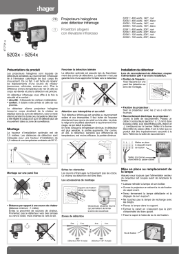
TPW / WPM
Elektronischer Taupunktmelder mit Normschienenbefestigung
Electronic dew-point sensor apt for fastening on standard rail
Détecteur du point de condensation électronique pour fixation sur rail standardisé
Avvisatore elettronico del punto di rugiada con fissaggio su guide standard
Achtung!
Attention!
D
Dieses Gerät darf nur durch eine Elektrofachkraft gemäß dem
Schaltbild auf dem Gehäuse / in der Bedienungsanleitung installiert werden. Dabei sind die bestehenden Sicherheitsvorschriften
zu beachten. Die Bedienungsanleitung muss für Bedien- und Wartungspersonal an frei zugänglicher Stelle aufbewahrt werden.
1. Anwendung und Funktion
GB
No persons other than expert electricians only must open this
device in due compliance with the wiring diagram imprinted on or
affixed to the housing or represented in the corresponding operating instructions. All expert electricians committed to the execution
of any such works must comply with the relevant safety regulations currently operative and in force. These operating instructions
must be kept at a place that can be accessed freely by the operating and/or servicing personnel in charge.
1. Application and function
Dieser elektronische Taupunktwächter wurde speziell zur Erfassung und Meldung des Taupunktes entwickelt. Er verhindert somit
bei korrekter Montage des Taupunktfühlers abtropfendes Kondenswasser von den gekühlten Teilen des Kühlkreislaufs. Hierzu
wird ein an geeigneter Stelle am Kühlkreislauf befindlicher Taupunktsensor ausgewertet und bei Betauung ein potentialfreier
Wechselkontakt umgeschaltet. Dieser Kontakt kann zur direkten
Unterbrechung der Kühlung oder zur indirekten Unterbrechung der
Kühlung durch Meldung an eine Gebäudeleittechnik genutzt werden. Die aktivierte Funktion „Kühlunterbrechung durch Taupunktauslösung“ wird durch eine rote Lampe am Gerät angezeigt.
Für andere, vom Hersteller nicht vorherzusehende Einsatzgebiete,
sind die dort gültigen Sicherheitsvorschriften zu beachten.
Eignung hierfür siehe Punkt 6. Gewährleistung.
2. Montage
This electronic dew point indicator has been specially designed for
the acquisition and indication of dew points. If installed correctly,
the device suits to prevent condensed water from dripping off the
cooled parts of a cooling circuit. To enable this, the data delivered
by a dew point sensor installed at an appropriate place at the cooling circuit are evaluated and, once a moisture condensation is detected, a potential-free changeover contact actuated. This contact
can either be used to disrupt the current cooling procedure directly
or can be applied for the indirect interruption of the cooling procedure through the initiation of a corresponding message that is
emitted to a superset building control system. A red lamp serves
to indicated if the function “cooling operation interrupt: formation
of condensed water detected” is active. Regarding other applications not to be foreseen by the manufacturer of this device, the safety standards concerning these applications need to be followed
and adhered to. Regarding the aptitude of the device for any such
other application, please refer to section 6 herein (Warranty).
2. Installation
Die Montage des Wächters erfolgt auf einer Normschiene. Hierzu
wird der Wächter mit den oberen Haken eingehängt und anschließend durch Aufdrücken auf die Normschiene eingeschnappt. Zum Abnehmen des Wächters von der Normschiene
sind mittels Schlitz-Schraubendreher zuerst die oberen Haken
durch Herausziehen der Lasche zu lösen und der Wächter auszuhängen. Zur einwandfreien Funktion muss der Taupunktsensor
an den Ort mit der größten Taupunktwahrscheinlichkeit an den
Kühlkreislauf montiert werden. Kann dieser Montageort nicht eindeutig festgelegt werden, besteht die Möglichkeit bis zu 5 Taupunktsensoren parallel an den Wächter anzuschließen. Vorzugsweise sollten die Taupunktsensoren am in den Raum führenden
Zulauf und/oder im Fensterbereich montiert werden.
3. Technische Daten
The indicator is installed on a standard rail. This can be realised
by hanging the electronic indicator up on the rail using the top
hooks the device is equipped with and by affixing it to the rail by
clicking it into place. The indicator can be removed by means of a
slot screwdriver. To do so, the upper hooks must be released by
pulling the lugs out first with the screwdriver. After that, the device
can be hung out. To ensure the perfect functioning of the device,
the required dew point sensor should be installed as close as possible to the place within the cooling circuit where the formation of
condensed water is most likely. If this place of installation cannot
be defined clearly, a total of up to 5 dew point sensors can be
connected to the indicator in parallel. Preferably, the required dew
point sensors should be installed on the supply line that leads into
the related room or should be installed close to the windows
3. Technical data
Versorgungsspannung: 24 V~/4
Leistungsaufnahme:
ca.1VA
Ausgang:
Relais als potentialfreier
Wechselkontakt (Umschalter)
Schaltvermögen:
max.10(3)A
Fühler:
TPF 341
Betriebsspannung TPS: 12V4
Elektrischer Anschluss: Schraubklemmen bis 2,5 mm2
Schutzart:
IP20
Schutzklasse:
0, Schutzklasse muss durch den
Einbauort z.B. Schaltschrank
gewährleistet werden.
zulässige
Umgebungstemperatur: -20 … +60°C
zulässige
Lagertemperatur:
-20 … +70°C
Befestigung:
Normschienenmontage
Gehäusewerkstoff
und Farbe:
Kunststoff ABS, Lichtgrau RAL 7035
Gewicht:
ca.110 g
Supply voltage:
Power consumption:
Output:
24 V~/4
approx. 1 VA
relay with potential-free changeover
contact
Switching capacity:
max.10 (3) A
Sensor:
TPF 341
Operating voltage TPS: 12 V4
Electrical connection: via terminal screws of up to 2.5 mm2
Degree of protection: IP20
Protection class:
0 (the place of installation is decisive for
the realisation of this protection class
(installation in a switch cabinet, f. ex.))
Admissible ambient
temperature:
-20 … +60° C
Admissible storage
temperature:
-20 … +70° C
Fastening:
on standard rail
Housing material
and colour:
plastic (ABS), light grey RAL 7035
Weight:
approx.110 g
1
4. Fühler
4. Sensors
Achtung: Berühren oder anderweitiges Verschmutzen der leiterbahnseitigen Sensoroberflächen führt zu Fehl- oder Nichtfunktion!
Der TPF 341 wird direkt mit zwei beiliegenden Kabelbindern an
eine Kühlleitung befestigt. Hierbei ist darauf zu achten, dass die
Leiterbahnseite dem Rohr abgewandt ist. Die Sensoroberfläche
des TPF ist nicht gekapselt und somit offen den Umweltbedingungen ausgesetzt. Auf Grund von eventuell auftretenden Langzeitverschmutzungen muss der Taupunktsensor reversibel verbaut
werden, um einen Austausch des Sensors ohne aufwändige Bauarbeiten zu gewährleisten. Reinigen des Sensors vor Ort ist nicht
möglich.
Attention!
Caution: The touching or other pollution of the conducting path
surfaces of the sensors will cause malfunctions or lead to a breakdown!
The TPF 341 is connected directly to the cooling line with the
enclosed cable straps that serve for this purpose. When doing so,
care must be taken to ensure that the conducting path surface
faces away from the related pipe or tube. As the sensor surface of
the TPF is not encapsulated, it is largely exposed to the
ambient conditions that prevail on site. On account of long-term
pollutions the dew point sensor may be exposed to, the sensor
must, in order to ensure that can be replaced without any need to
perform time consuming construction works, be installed in an
easily removable manner. The cleaning of the sensor on site is
impossible.
Attenzione!
F
Uniquement des personnes qualifiées en matière d’électricité doivent ouvrir ce dispositif en conformité avec le schéma des connexions imprimé sur le boîtier ou apposé à celui-ci ou bien représenté dans les notices d’instructions correspondantes. Tous électriciens spécialisés chargés de l’exécution de tels travaux
doivent se conformer aux prescriptions de sécurité actuellement
en vigueur s’y rapportant. Les instructions de service sont à garder à un lieu librement accessible pour les personnels de service
et d’entretien.
I
Questo apparecchio può essere installato solo da un elettricista
qualificato in base allo schema di collegamento riportato sulla scatola / nelle istruzioni per l’uso. Al riguardo rispettare assolutamente
le norme di sicurezza in vigore. Custodire le istruzioni per l’uso in
un punto accessibile al personale di servizio e di manutenzione.
1. Application et fonctionnement
1. Applicazione e funzionamento
Ce détecteur du point de condensation a été spécialement conçu
pour la saisie et l’indication du point de condensation. Lorsque
installé de manière correcte, le dispositif convient pour prévenir
que pas de l’eau condensée ne pourra dégoutter des parties réfrigérées du circuit frigorifique. Afin d’obtenir ça, les données délivrées par un détecteur du point de condensation installé à un lieu
approprié sur le circuit frigorifique sont évaluées et, au moment où
une condensation d’humidité est détectée, un contact à permutation libre de potentiel est actionné. Ce contact peut être utilisé soit
directement afin d’interrompre le processus de réfrigération actuellement en cours ou peut également être utilisé pour déclencher
l’interruption du processus de réfrigération par l’émission d’un
message au système de gestion technique du bâtiment supérieur.
Une lampe rouge sert pour l’indication de l’état actif de la fonction
«interruption de l’opération de refroidissement: formation de condensât détectée». Concernant des autres applications pas à
prévoir par le fabricant de ce dispositif, les standards de sécurité
se rapportant à ces applications sont à respecter. En ce qui
concerne l’aptitude ou l’approbation du dispositif pour des telles
applications, veuillez également faire attention aux informations de
garantie dans chapitre 6. (Garantie) dans cette notice d’instructions.
Questo sensore elettronico del punto di rugiada è stato concepito
soprattutto per rilevare e segnalare il punto di rugiada. Se il sensore del punto di rugiada è correttamente montato esso impedisce di
conseguenza gocciolamenti della condensa della parti raffreddate
del circuito di raffreddamento. Allo scopo vengono analizzati i dati
di un sensore del punto di rugiada, montato su un punto adeguato
del circuito di raffreddamento, e a seguito di formazione di rugiada
viene attivato un contatto di commutazione a potenziale zero.
Questo contatto può essere utilizzato per interrompere il raffreddamento direttamente o indirettamente con segnalazione ad un sistema di controllo del fabbricato. La funzione attivata «Interruzione del raffreddamento per attivazione del punto di rugiada» viene
segnalata da una spia rossa sull’apparecchio. Per altri settori d’impiego, non previsti dal costruttore, osservare le norme di sicurezza
specifiche. Per la compatibilità vedi punto 6 (Garanzia).
2
2. Installation
2. Montaggio
Il montaggio dell’avvisatore avviene su una guida standard. Allo
scopo l’avvisatore viene agganciato con i ganci superiori ed infine
innestato con compressione sulla guida standard. Per togliere
l’avvisatore dalla guida standard disimpegnare prima i ganci superiori con un cacciavite a ad intaglio estraendo la linguetta e
sganciare quindi l’avvisatore. Per garantire il perfetto funzionamento il sensore del punto di rugiada deve essere applicato sul punto
più esposto alla formazione di rugiada nel circuito di raffreddamento. Se il punto di montaggio non può essere chiaramente definito, sussiste la possibilità di collegare in parallelo sull’avvisatore
fino a 5 sensori del punto di rugiada. Preferibilmente i sensori del
punto di rugiada dovrebbero essere montati all’ingresso del locale
e/o in prossimità di finestre.
Le détecteur est prévu pour l’installation sur un rail standardisé.
L’installation se fait en accrochant le dispositif sur le rail par moyen
des crochets supérieurs du dispositif qui permettent de l’y encliqueter. L’enlèvement du détecteur se fait par moyen d’un tournevis
pour vis à fente. Pour faire ça, il faut d’abord relâcher les crochets
supérieurs en retirant les colliers de fixation par moyen du tournevis. Après ceci, le dispositif peut être enlevé. Afin de garantir le
fonctionnement parfait du dispositif, il faudrait que le détecteur du
point de condensation soit installé le plus proche que possible au
lieu sur le circuit frigorifique où la formation de l’eau condensée
aura lieu le plus vraisemblablement. Pour des cas où il n’est possible de définir clairement ce lieu d’installation, le dispositif permet
le raccordement parallèle de jusqu’à 5 détecteurs du point condensation. De préférence, il faudrait installer les détecteurs du
point de condensation requis sur la conduite d’alimentation qui
mène dans la salle correspondante ou bien les installer près des
fenêtres.
3. Caractéristiques techniques
3. Dati tecnici
Tension d’alimentation:
Puissance absorbée:
Sortie:
24 V~/4
env. 1 VA
relais avec contact de permutation
libre de potentiel
Pouvoir de coupure:
max.10 (3) A
Détecteur:
TPF 341
Tension de service TPS: 12 V4
Raccordement électrique: par moyen de bornes à vis de
jusqu’à 2.5 mm2
Type de protection:
IP20
Indice de protection:
0 (le lieu de l’installation est décisif
pour la réalisation de cet indice de
protection (installation dans une
armoire de commande, p. ex.))
Température ambiante
admissible:
-20 … +60°C
Température de stockage
admissible:
-20 … +70°C
Fixation:
sur rail standardisé
Matériel du boîtier et
couleur:
matière plastique (ABS),
gris clair RAL 7035
Poids:
env.110 g
Tensione alimentazione:
Consumo elettrico:
Uscita:
Capacità comando:
Sensore:
Tensione di regime TPS:
Collegamento elettrico:
Tipo protezione:
Categoria protezione:
Temperatura ambiente
ammessa:
Temperatura magazzino
ammessa:
Fissaggio:
Materiale scatola e colore:
Peso:
24 V~/4
ca.1 VA
relè per contatto di commutazione a
potenziale zero (commutatore)
max.10 (3) A
TPF 341
12 V4
morsetti a vite fino a 2,5 mm2
IP20
0, categoria protezione tramite il punto
di montaggio, es. quadro di comando
-20 … +60° C
-20 … +70° C
montaggio su guida standard
materiale sintetico ABS,
grigio chiaro RAL 7035
ca.110 g
4. Sensori
4. Détecteur
Attention: Touchant les surfaces des conducteurs imprimés du
détecteur du point de condensation de même que le dépôt d’autres salissures peut aboutir à des dysfonctionnements ou à une
défaillance du détecteur!
L’installation du TPF 341 se fait directement sur la conduite frigorifique par moyen des colliers serre-câble également livrés avec
celui-ci. Lors d’une telle installation il faut toujours faire attention à
ce que la face des conducteurs imprimés détourne de la conduite
concernée. Par raison du fait qu’il n’est encapsulé, le détecteur est
exposé aux conditions ambiantes qui dominent sur le site sans
être protégé contre cellesci. Pour cause des pollutions et salissures dont le détecteur du point de condensation peut être exposé, il
faut qu’il soit, pour assurer qu’il peut être remplacé sans aucune
nécessité de travaux de construction d’une longue haleine, installé
de telle façon qu’il puisse être enlevé aisément. Il n’est possible de
nettoyer le détecteur sur site.
Attenzione: evitare di toccare o di sporcare le superfici laterali
conduttive del sensore, altrimenti si possono verificare funzionamenti scorretti o anomalie!
Il sensore TPF 341 viene direttamente fissato su una tubazione di
raffreddamento con le due fascette fermacavo accluse. Al riguardo
assicurarsi che il lato della pista conduttiva sia rivolta in direzione
opposta al tubo. La superficie del sensore TPF non è incapsulata
e, quindi, completamente esposta agli agenti atmosferici. Tenuto
conto degli accumuli di sporco nel tempo, il sensore del punto di
rugiada deve essere montato con sistema reversibile, facilitando
così la sostituzione del sensore senza operazioni complesse. Non
è possibile pulire il sensore sul posto.
3
5. Anschluss-Schaltbild / Wiring Diagram /
Schéma de connexion / Schema di collegamento
Taupunktmeldung
Dew-point indication
Indication de point de
condensation / rosée
Segnalazione del punto
di rugiada
Maßbilder / Dimensioned Drawings /
Schéma de connexion / Schema di allacciamento
Taupunktsensoren
Dew-point sensors
Détecteur de point de
condensation / rosée
Sensori del punto
di rugiada
6. Gewährleistung / Warranty / Garantie / Garanzia
Die von uns genannten technischen Daten wurden unter Laborbedingungen nach allgemein gültigen Prüfvorschriften, insbesondere
DIN-Vorschriften, ermittelt. Nur insoweit werden Eigenschaften zugesichert. Die Prüfung der Eignung für den vom Auftraggeber vorgesehenen Verwendungszweck bzw. den Einsatz unter Gebrauchsbedingungen obliegt dem Auftraggeber; hierfür übernehmen wir keine
Gewährleistung. Änderungen vorbehalten.
The technical data specified herein have been determined under laboratory conditions and in compliance with generally approved test
regulations, in particular DIN standards. Technical characteristics can only be warranted to this extent. The testing with regard to the
qualification and suitability for the client’s intended application or the use under service conditions shall be the client’s own duty. We
refuse to grant any warranty with regard thereto. Subject to change without notice.
Les données techniques indiquées dans cette notice d’instructions ont été déterminées sous conditions laboratoires en conformité avec
des prescriptions d’essai généralement approuvées, notamment les normes DIN. Les caractéristiques techniques ne peuvent être
garanties que dans cette mesure. La vérification du dispositif en rapport à sa qualification et appropriation pour l’application prévue ou
son utilisation sous conditions de service incombe au client. Nous n’assumons aucune garantie à cet égard. Sous réserve de modifications techniques.
I dati tecnici indicati in queste avvertenze di montaggio sono stati rilevati in laboratorio in conformità con le norme di controllo correnti,
soprattutto con le norme DIN. La caratteristiche tecniche vengono garantire solo in tale misura. Il controllo del dispositivo in relazione
all’idoneità per lo scopo di destinazione previsto dal committente e all’impiego in condizioni di servizio è a carico del cliente. Non assumiamo alcuna garanzia al riguardo. Salvo modifiche di ordine tecnico.
Glen Dimplex Deutschland GmbH
Am Goldenen Feld 18
D-95326 Kulmbach
Telefon: +49(0)9221 709-562
Fax:
+49(0)9221 709-565
4
FD 8706
Scaricare