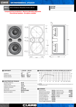
Aptica
Manuale d’istruzioni
Owner’s manual
brightness in sound
1
2
3
Gentile Cliente,
la ringraziamo per avere scelto una coppia
di diffusori Albedo. Prima di procedere al
collegamento al resto dell’impianto ed al
fine di ottenere il miglior risultato possibile,
la invitiamo a leggere questo manuale.
Ulteriori informazioni sull’interfacciamento
e sulla collocazione nel locale d’ascolto
potranno essere richieste al suo negoziante o
direttamente all’indirizzo di posta elettronica
[email protected].
Dear Customer,
We would like to thank you for choosing a
pair of Albedo speakers. Before connecting
them to the amplifier and in order to reach
the best result, please read this handbook.
Further information about installation and
listening room needs can be asked your
dealer technical staff or directly at the mail
address [email protected].
Questo prodotto risponde alla normativa della
Unione Europea riguardante la Compatibilità
Elettromagnetica (EMC). A causa dei magneti degli
altoparlanti, questo prodotto produce un campo
magnetico che potrebbe disturbare il funzionamento
di computer o schermi televisivi posti nelle immediate
vicinanze.
This product meets the requirements of European
Union Electromagnetic Compatibility (EMC)
Directive. Because of loudspeakers permanent
magnets, this product produces magnetic fields
and it is not recommended to be positioned in very
close proximity to computer monitors or television
set.
made in Italy
4
n
L’imballo
n
Package
I diffusori acustici Albedo vengono spediti in
imballi di cartone completi di inserti interni in
polylam. Ciò assicura una migliore protezione
del prodotto ed un piccolo contributo alla
salvaguardia dell’ambiente, poiché materiali
riciclabili. Raccomandiamo di conservare
gli imballi per un eventuale uso futuro ed
eventualmente appiattirli per risparmiare
spazio, dopo averli scomposti.
Albedo loudspeakers are shipped in hard
cardboard boxes with polylam foam internal
pads. This solution provides a safe arrival and
a little aid to environment protection, because
recyclable materials. We recommend saving
these boxes for a possible future shipment.
Boxes can be disassembled and flattened in
order to save storing space.
Nota 1: Le coppie sono identificate dallo stesso
numero seriale seguito dalla lettera A o B (p. es.
il 001/A va accoppiato con il 001/B). Contattate
immediatamente il vostro rivenditore nel caso i
numeri serali risultino discordanti.
Note 1: Matched pairs are identified by the capital
letter A or B following the serial number (i. e. 001/A
matches with 001/B) on the label. Please contact your
dealer immediately if your pair is not matched in this
way.
Nota 2: Per ragioni di sicurezza, ogni diffusore
viene imballato con la base metallica smontata. Per
assemblarla, utilizzare le tre viti e la apposita chiave
in dotazione. Fare attenzione al peso della base al
fine di non provocare danni a sé o ad altre persone.
Note 2: For best package integrity, any speaker is
packed with metal base disassembled. For assembling
it, use the three screws and wrench supplied. Pay
attention to metal plate weight in order not to do
harm yourself or other people.
5
n
Montaggio dei piedini
I quattro piedini forniti a corredo forniscono
il migliore accoppiamento tra diffusore e
pavimento. Per installarli, basta avvitarli
completamente nei quattro fori della base. Il
livellamento può essere raggiunto svitando
leggermente uno o più piedini e stringendo
infine ciascuna rondella di blocco. Nel caso
di pavimenti in parquet o in altro materiale
delicato, raccomandiamo l’uso dei quattro
dischetti in dotazione, appositamente
sagomati per tale uso.
n
Spikes installing
The four spikes provide for best coupling
of your loudspeaker to the floor. To install
spikes, simply thread them into the four base
holes. For best levelling, raise or lower one or
more spikes and tighten locking washers. For
parquet or any fragile floor, we provide four
stainless steel round pads that match the pin
end of screws.
6
n
Collegamenti
Ogni diffusore è dotato di una coppia di
morsetti di alta qualità a cui collegare i cavi
provenienti dall’amplificatore. Possono
essere utilizzate terminazioni a banana da
4 mm, a forcella da 6 e 8 mm e cavi spellati
fino a 4 mm 2 (11 AWG). Assicurarsi che venga
rispettata la corretta polarità, il positivo va
collegato al morsetto rosso, il negativo a
quello nero. Usando terminazioni a forcella o
cavo spellato, non forzare esageratamente il
serraggio dei morsetti.
n
Wiring
The speaker is equipped with two high
quality pole terminals for connecting
speaker cables. They accept 4 mm banana
plugs, 6 and 8 mm spades and crimped
cable ends up to 4 mm 2 (11 AWG). Check
to insure the correct polarity, positive lead
must be connected to red terminal, negative
lead to black terminal. Using spades
or crimped cable, do not overtight the
terminals.
7
n
Rodaggio
I vostri diffusori Albedo non esprimeranno
le loro migliori prestazioni appena collegati
al resto dell’impianto. Ciò è dovuto ad una
serie di fattori elettrici e meccanici come le
caratteristiche intrinseche dei componenti
del filtro crossover e delle sospensioni degli
altoparlanti. Solo dopo un adeguato periodo
di rodaggio i diffusori raggiungeranno
le loro migliori prestazioni. Parametri
come l’immagine sonora, la profondità
ed il controllo del basso raggiungeranno
il massimo solo dopo un centinaio di
ore di ascolto. Si consiglia pertanto di
non procedere nella messa a punto fine
dell’impianto prima di questo periodo.
n
Break-in period
Your new Albedo loudspeakers will not
perform at best when first installed in your
system. This is due to some electric and
mechanical reasons as properties of filter
components and drivers suspensions. Only
after this break-in period the full performance
of the system will be realized. After a 100
hours break-in period all listening parameters
as sonic image, sound stage and bass control
will reach their best. It is therefore suggested
that any fine tuning of the system be delayed
until after the break-in period is completed.
8
n Posizionamento in ambiente
n Speaker placement
Nella messa a punto del’impianto, una speciale
attenzione va posta nel posizionare correttamente
i diffusori, dato che ciò avrà grande importanza nel
bilanciamento tonale finale. E’ bene scegliere ambienti
in cui pareti e soffitto abbiano differenti dimensioni,
cioè la cui forma sia il più possibile lontana da quella
cubica. Ciò limiterà la formazione di sgradevoli onde
stazionarie a bassa frequenza. Tappeti o tendaggi,
invece, avranno un positivo effetto sul controllo delle
alte frequenze, anche se un eccesso di superfici
assorbenti può “uccidere” l’acustica dell’ambiente. E’
anche importante tenere sotto controllo il suono che,
riflesso dalle pareti laterali, arriva direttamente alle
orecchie dell’ascoltatore. Limitare tali riflessioni è molto
importante in quanto esse tendono a mascherare le
informazioni di ambienza presente nelle registrazioni. A
tale scopo non è necessario trattare l’intera stanza ma
In setting up your new speakers in the room, special
attention should be given to their positioning. This
choice will have an important influence on the acoustic
balance of the whole system. Rooms with not similar
dimensions of walls and ceiling must be preferred
because these differences can limit the formation of
low frequency standing waves. Carpets and curtains
have a positive effect on the high frequency response,
absorbing excessive reflections from floor and walls,
even if too many can “kill” the timbre of the room. It is
also important to control the early reflections arriving
from the sidewalls to the listening position, damping
this first reflection spots is strongly recommended,
because these reflections tend to obscure the
ambient information in the recording. Anyway, it is
not necessary to acoustically treat the entire room
to achieve a good result, but strategic treatment of
(A)
9
basta individuare tali zone e renderle acusticamente non
riflettenti. Immaginiamo dunque che il suono si comporti
come la luce e la parete come uno specchio. Muovendo
uno specchio sulla parete laterale, la zona da trattare
acusticamente sarà individuata dalla posizione in cui
l’ascoltatore vedrà gli altoparlanti riflessi nello specchio
stesso. Per quanto riguarda il punto in cui collocare
i diffusori, si può affermare che non ci siano regole
precise ed universalmente valide per ogni ambiente di
ascolto. La raccomandazione basilare è di porli almeno a
80 - 100 cm dalle pareti laterali e di fondo e mantenere
una distanza reciproca compresa tra gli 2.5 e 3.5 metri. I
diffusori posti paralleli tra loro (A) tendono a creare una
immagine più ampia, mentre facendoli convergere verso
l’ascoltatore (B, C) aumentano la focalizzazione delle
sorgenti sonore. La scelta dell’angolo più opportuno è
operazione alquanto delicata e solo prove successive di
ascolto possono portare alla scelta migliore per il vostro
ambiente di ascolto.
(B)
specific locations can produce considerable benefits.
In order to find these locations, remember that sound
waves reflect from a surface as a mirror reflects light,
so, using a simple mirror placed on the wall, the most
important location for sound absorbing is the point
where the listener can see speaker drivers in the
mirror. About positioning the speakers in the room,
there are no fixed rules that are universally valid for
every room. We recommend placing the speakers
at least 80 - 100 centimetres (3 feet) away from the
corners and the side and back walls. The distance
between the speakers themselves should be between
2.5 and 3.5 meter s (8 - 12 feet). Facing speakers (A)
straight forward, they tend to create larger sound
stage; as they are rotated toward the listening position
(B, C), image becomes more compact with increased
focus. This kind of adjustment is rather delicate and
experimentation is necessary to achieve the best angle
for your listening room.
(C)
10
n
Manutenzione
I diffusori non necessitano di particolare
manutenzione se si eccettua la normale pulizia
generale. Per il mobile può essere usato
un panno morbido. Non utilizzare prodotti
contenenti ammoniaca, solventi aggressivi o
materiali abrasivi. Evitare di porre i diffusori
troppo vicini a fonti di calore o alle finestre,
specialmente in estate. Evitare la luce diretta
del sole. Non toccare le membrane ceramiche
degli altoparlanti. Queste semplici precauzioni
contribuiranno a mantenere in perfette
condizioni i vostri diffusori per molti anni.
n
Maintenance
Speakers do not require any particular
maintenance apart from occasional
general cleaning. Clean the wooden part
of the cabinet with a soft cloth. Do not
use cleaners that contain ammonia, strong
solvents or abrasive materials. Avoid placing
speakers close to heat sources or windows,
particularly in summer. Avoid direct
sunlight. Never touch speakers ceramic
membranes. These simple considerations
will keep your Albedo speakers in perfect
condition for many years.
11
n
Garanzia
Albedo garantisce i materiali, la costruzione
e il corretto funzionamento per un periodo di
tre anni. La garanzia è valida a partire dalla
data di acquisto presente sul documento
fiscale di acquisto. Ogni intervento non
autorizzato sul prodotto implica la decadenza
della garanzia. Albedo si riserva il diritto
di modificare e migliorare i propri prodotti
senza assumere alcun impegno ad applicare
tali modifiche ai modelli precedenti. Albedo
non è responsabile di qualsiasi danno
diretto o indiretto derivante da difetti
di funzionamento o fabbricazione. Ogni
riparazione non coperta dalla garanzia verrà
addebitata all’acquirente. Ogni diffusore
che necessiti di intervento deve essere fatto
pervenire al negoziante nell’imballo originale
per essere spedito in fabbrica o al centro
autorizzato insieme ad una descrizione del
difetto. Le spese di spedizione sono a carico
del cliente.
n
Warranty
Albedo warrants the materials, workmanship
and proper functioning for a period of three
years. Italian warranty is valid from the
purchase date shown on the receipt and only
in Italy. Unauthorized dismantling of the
product will render this warranty void. Albedo
reserves the right to make changes in design
and improvements upon its products without
necessarily assuming an obligation to retrofit
such changes upon previously manufactured
models. Albedo shall in no event be obligated
for any incidental or consequential damages
as a result of any defect or any warranty
claim, whether expressed or implied. Any
replacement of parts not covered by the
warranty will be charged to the customer. Any
speaker requiring repairs must be taken to the
retailer in its original packaging for delivery
to our offices or authorized service center
with a description of the defect. If shipping is
required, such costs are charged to the client.
For all foreign markets, the Albedo local
distributor is responsible for establishing any
and all rules governing warranty in accordance
with the rules and regulations that apply in
each market. This includes length of warranty,
location where repairs may be effected, costs,
if any, and conditions pertinent to fulfilling the
conditions of warranty.
12
APPROFONDIMENTO
n
La filosofia di progetto
Illustrare le motivazioni, lo sviluppo e la
realizzazione di un diffusore è anche l’occasione
per riflettere su molti aspetti della storia
recente della progettazione e della fruizione in
alta fedeltà. La filosofia di progetto di Albedo
scaturisce da una analisi approfondita delle due
problematiche che stanno alla base dell’universo
della riproduzione sonora: da una parte lo sviluppo
tecnologico e, nel caso specifico, il tendere allo
stato dell’arte nella realizzazione di un sistema di
altoparlanti; dall’altra, le esigenze reali dell’utente
in termini di prestazioni elevate, affidabilità e
praticità d’uso. La discussione su questi problemi è
la linfa del dibattito nel nostro mondo e speriamo
che questo contributo possa quindi interessare
sia l’appassionato che l’addetto ai lavori. Dal
punto di vista dell’appassionato di riproduzione
domestica, il mercato offre molti ottimi prodotti,
in particolare nel settore dei sistemi di altoparlanti.
Se il suo desiderio è, però, quello di entrare in
possesso di un diffusore il più possibile naturale
nella ricostruzione timbrica e prospettica ma senza
limitazioni in frequenza e dinamica, deve rivolgersi
ad un sistema da pavimento.
Le motivazioni che, attraverso un lavoro di ricerca
e di sviluppo, hanno portato alla realizzazione
della Aptica nascono dalla stessa intuizione che
era alla base del nostro primo modello, le HL 2.2,
realizzare cioè una cassa acustica che avesse la
precisione di un minidiffusore ma che offrisse una
gamma bassa da grande sistema. E’ evidente che
una risposta definiva a questa domanda è elusiva
nella misura in cui ogni progetto, anche quello
frutto di risorse illimitate e senza vincoli di costi, è
sempre un compromesso dettato da altri vincoli di
natura tecnica e culturale. Quello di cui eravamo
(e siamo) certi è che la domanda ha senso perché
TECHNICAL NOTES
n
Design philosophy
As we present here the original motivation, the
development and the actual realization of a
loudspeaker system, we also take the occasion to
reflect on many aspects of the recent history of
design and listening enjoyment of High Fidelity
sound. Albedo’s project philosophy has its roots
in a thorough analysis of the two basic problems
in the area of sound reproduction: on one side the
technological development, and in this specific
case, the state-of-the-art required for the design
of a loudspeaker system, while on the other
side there are the actual user requirements, as
high quality sound performance, reliability and
practicality of use. The ongoing debate on these
two subjects is the main motivation for technical
advances in our world, and we hope therefore that
this paper may be of interest both for the audio
amateur as well as for the professional. From the
point of view of the audio amateur, the market
offers an extremely wide range of fine products,
in particular in the area of loudspeaker systems;
however, if his aim is to get a speaker that is, at
the same time, tonally well balanced, with a good
soundstage without strong limitations in frequency
and level, the most common choice is a floor
standing system. The motivations that led to the
creation of the Aptica loudspeaker originate from
same intuition which our first model, the HL 2.2,
was based on, making a system with the precise
soundstage of small bookshelf, with a really robust
bass range. It is clear that a final answer to this
question is elusive, since every project, even the
ones with unlimited budget and therefore free of
any cost limitations, is anyway still the result of a
compromise dictated by other technical or cultural
restrictions. However, we were (and still are)
certain that these challenges make sense since
13
individua e circoscrive un problema ben definito
e, come sanno quelli che fanno ricerca a qualsiasi
livello, la cosa più importante è porsi il quesito
giusto.
n
La tecnica
I tre aspetti salienti comuni ad ogni progetto
Albedo sono i seguenti:
1) Sistema a fase lineare.
2) Caricamento del woofer a linea di trasmissione
equalizzata acusticamente.
3) Accoppiamento meccanico ultra-rigido.
Questi ingredienti sono stati fin da principio
considerati fondamentali per soddisfare le
richieste di progetto. La linearità nella risposta
in fase è un requisito imprescindibile per la
correttezza della riproduzione dei transienti e,
di conseguenza, per un’accurata ricostruzione
prospettica delle sorgenti e per focalizzarne la
collocazione spaziale. Per ottenere il risultato
voluto, si deve combinare la disposizione
geometrica dei trasduttori con la topologia della
rete di crossover (un primo ordine acustico) al
fine di compensare esattamente gli sfasamenti
intrinseci delle vie. E’ da notare che, a causa di
meccanismi psicoacustici alla base del nostro
sistema percettivo, che solo ora si comincia a
comprendere, la coerenza della riproduzione
nel dominio del tempo ha anche un ruolo
fondamentale per la correttezza timbrica, ruolo
altrettanto importante della linearità nella risposta
in frequenza. La scelta del caricamento del
woofer in linea di trasmissione è stata dettata
dal convincimento che questo sistema è quello
che garantisce allo stesso tempo l’incremento
quantitativo più consistente con una resa
qualitativa senza compromessi in termini sia
timbrici che di risposta ai transitori. D’altra
parte, per ottenere le prestazioni desiderate si
è realizzato un sistema totalmente innovativo
they focus on a well defined problem and, as it is
well known to anybody who may work in research,
the most important thing in all fields of research is
to ask the right questions.
n
Technical issues
There are three main aspects of all Albedo
projects:
1) Linear phase system.
2) Acoustically equalized transmission line woofer
loading.
3) Ultra stiff mechanical coupling.
From the very beginning these elements have
been considered fundamental to achieve
the design specifications. The linear phase
response is an absolute requirement for the
accurate reproduction of the transients and,
as a consequence, for a correct perspective
reproduction of the sound sources and the
focusing of their physical positioning. To achieve
these objectives, the geometrical position of the
transducers must be combined with the topology
of the crossover network (an “acoustic” first
order) with the objective to exactly compensate
for the intrinsic phase shifts of the ways. It is to
be noted that, at the light of recently discovered
psychoacoustic mechanisms at the base of our
perception system, which just now are beginning
to be properly understood, the coherence of
reproduction in the time domain also plays a
major role for tonal balance, role that is at least
as important as the linearity in the frequency
response. Our choice, of loading the woofer
through the transmission line, is driven by our firm
belief that this guarantees the best quantitative
increment in bass response without compromising
quality in tonal balance and response to transients.
On the other hand, in order to reach this desired
performance we developed a very innovative
system which represents a major step forward in
14
che costituisce un concreto passo in avanti
nella tecnologia delle linee di trasmissione. Per
ottenere una sensibilità allineata a quella del
resto della gamma si è optato per una linea
coibentata solo sulle pareti, in cui il controllo
delle risonanze è affidato ad un risuonatore
opportunamente accordato. Allo stesso tempo,
la sezione decrescente consente di accordare
il sistema ad una frequenza più bassa, a parità
di lunghezza della linea, consentendo una
riproduzione della gamma bassa più estesa a
parità di driver utilizzato. Per quel che riguarda
l’aspetto puramente meccanico, gli altoparlanti
montati su un sistema devono lavorare in modo
da convertire interamente in energia sonora
l’energia elettrica fornita dall’amplificatore. Questo
obiettivo si raggiunge tramite un accoppiamento
ideale altoparlante-cabinet e cabinet-supportoambiente e l’eliminazione degli effetti dovuti
ai modi di risonanza del sistema meccanico
complessivo. Insieme a questi criteri, diciamo di
filosofia progettuale, va detto che si sono adottati
dei componenti che meglio beneficiassero di
queste soluzioni. Gli altoparlanti Accuton hanno
membrane ceramiche a bassa massa ultra-rigide
per offrire una eccellente risposta ai transitori e
distorsione ridottissima e sono tutti selezionati in
coppie in modo da garantire le minime variazioni
nel raggiungimento delle specifiche, contribuendo
alla saldezza della ricostruzione prospettica; nel
crossover sono usate bobine in aria e condensatori
al poliestere su una basetta a doppia faccia con
rame ad alto spessore.
the technology of transmission lines. To achieve a
sensitivity aligned with the rest of bandwidth, we
chose an “empty” line only stuffed on its walls, in
which the control of resonances is performed by
a properly tuned resonator. At the same time, the
decreasing section allows to tune the system to a
frequency that is lower than it would be possible
with a constant section line of the same length,
allowing therefore an extension of low frequencies
which is frankly unimaginable for a speaker of such
small dimensions. As far as the purely mechanical
aspect, the speakers in a system must work in such
a way to convert all electrical energy provided
by the amplifier into sound energy. This objective
can be achieved through an ideal speaker-cabinet
coupling and of the overall system of cabinetsupport-listening environment, and through
the elimination of the spurious effects due to
the resonance modes of the overall mechanical
system. In addition to these criterions, which
we could call design philosophy, we adopted
components that would best benefit from these
solutions: the Accuton transducers are built with
ceramic, ultra stiff, low mass, diaphragms which
provide excellent transient response and very low
distortion. They are made available in matched
pairs to guarantee the lowest deviation from the
specifications, therefore contributing to a firm,
reliable soundstage. In the crossover network we
used air core coils and poly capacitors, mounted
on a double layer high thickness copper board.
n La risposta in fase
There are several articles for an interested reader
about the problems related to the measurement
and interpretation of phase response. They are
also the subject of expressely written notes [1,
2] available on our website. In any case, we can
say that an electro-acoustic system with a linear
phase response is able to reproduce complex
I problemi della misura e della valutazione
della risposta in fase, per chi fosse interessato
all’argomento, sono stati oggetto di un apposito
articolo apparso sulla rivista Fedeltà del Suono
[1, 2]. Comunque, possiamo in breve dire che
n
Phase response
15
un sistema a fase lineare ha la caratteristica di
potere riprodurre nella sua forma pressoché
originale un impulso [3]. Ora, visto che un impulso
può essere visto come l’insieme di innumerevoli
componenti sinusoidali a varia frequenza, la
corretta ricostruzione dell’impulso significa che
tutte le frequenze inviate al diffusore vengono
riprodotte contemporaneamente, ovvero senza
ritardi temporali reciproci. La natura impulsiva
del segnale musicale fa dunque immaginare
quanto sia riduttivo considerare unicamente la
risposta in frequenza di un diffusore. Per ottenere
tale comportamento, si è agito su due fronti
contemporaneamente: allineare fisicamente
gli altoparlanti e dotarli di una rete di filtro
che permettesse di mantenere tale coerenza
temporale. E’ ormai da qualche anno che i filtri
del primo ordine sono “di moda”, ma ci preme
sottolineare che un filtro elettrico del primo
ordine, da solo, non garantisce alcun allineamento
in fase. L’incrocio del primo ordine deve
essere acustico (e non elettrico) e presuppone
l’allineamento fisico dei trasduttori.
n La linea di trasmissione
I sistemi basati sulla teoria disponibile finora
erano molto semplici: l’altoparlante per la gamma
bassa irradia con la faccia anteriore in ambiente
e con quella posteriore in un condotto (un
tubo) uniformemente riempito di un materiale
fibroso fonoassorbente a sua volta irradiante
nell’ambiente. L’emissione da parte del condotto
si somma, in ampiezza e fase, a quella anteriore
in modo da estendere e regolarizzare la gamma
bassa; allo stesso tempo l’altoparlante lavora
nelle migliori condizioni perché il carico acustico
del condotto pieno è particolarmente favorevole.
La possibilità di scendere in frequenza viene
offerta dal fatto che il condotto pieno di materiale
assorbente ha una lunghezza effettiva maggiore
impulse signals without phase distortions [3].
This means that every harmonic components
in input appear in the output without any time
delay among the components. Now, since impulse
can be seen as the superposition of an infinite
number of sinusoidal components (“harmonics”),
correct reproduction of an impulse means that
all harmonic components sent to the speaker are
reproduced without any time delay introduced
among them and in form virtually identical to
original. The very nature of impulse-type musical
signal indicates therefore how limiting it can be to
only consider the frequency response, and not the
phase response, of a loudspeaker system. In order
to achieve this goal of a linear phase response,
Albedo worked on two fronts at the same time:
first, aligning physically the acoustic centers of
the speakers, and second, equipping them with a
filtering network to achieve such time coherence.
It is now several years that first order filters are
widely used, however, we would like to remark
that a first-order electric filter does not provide,
by itself, a linear phase response. The first-order
crossover must be acoustic (and not electrical)
and is therefore implemented by starting with the
physical alignment of acoustic centers.
n
Transmission line
Transmission line loudspeaker systems based on
the theory available up to a while ago were quite
simple: the low-end driver (either the woofer or the
mid-woofer) produces a front emission towards
the environment and a rear emission in a duct (a
“line”) uniformly stuffed with a fibrous material
through which it emits into the environment. This
second emission, from the “port” of the duct, gets
combined in amplitude and phase with the frontal
one, in a way that extends and regularizes the
low-frequency range; at the same time the speaker
works under best conditions since the acoustic
16
di quando è pieno di semplice aria. Esso risuona
quindi ad una frequenza sufficientemente bassa
da ottenere una buona estensione della risposta
in frequenza. Inoltre, al di sopra di una data
frequenza di taglio l’assorbente si comporta da
filtro e riduce quindi l’emissione del condotto
alla frequenze in cui si ha interferenza distruttiva
(controfase) con l’emissione principale. Il motivo
fisico per cui questo avviene è stato illustrato
da Bradbury [4]: quello che succede è che il
materiale fibroso che riempie il condotto, a
frequenza sufficientemente bassa, si accoppia
con le onde acustiche in modo tale che il suono si
propaga in un mezzo più denso e meno elastico
dell’aria e viaggia più lentamente. Al di sopra
della frequenza di taglio, che è determinata dalla
densità e dalla struttura del materiale fibroso,
l’accoppiamento finisce e si ha solo un effetto
di filtraggio (ad una pendenza di 6 dB/ott).
Su queste premesse, ci mettemmo a lavorare
con materiali vari e tubi di varie lunghezze.
Realizzammo un programma di simulazione del
sistema, che dava la risposta complessiva, quella
del condotto, l’impedenza, etc. e cominciammo
a fare dei confronti con le misure fatte con il
sistema Clio su un sistema vero [7, 8]. Risultato:
fra la teoria e le misure c’erano delle discrepanze
notevoli. Provammo materiali fibrosi di ogni tipo,
dalle lane naturali o artificiali al cotone in varie
conformazioni, dalle fibre acriliche ai poliuretani;
abbiamo provato addirittura con la lana d’acciaio:
sistematicamente il risultato sperimentale era
inferiore alle attese, sia in termini di estensione
sulle basse frequenze che in termini di efficienza.
La conclusione inevitabile era che il modello
di Bradbury fosse sbagliato o, quanto meno,
incompleto. Una prima modifica della teoria
che abbiamo adottato è stata allora quella di
tenere conto della elasticità e della dissipazione
intrinseca delle fibre; l’accordo con le misure
è migliorato ma non in maniera determinante.
load presented by the stuffed duct is particularly
favourable. The possibility to extend the range
further into the bass frequencies is provided by
the fact that once the duct is filled with phonoabsorbing material it has an effective length which
is greater than a line simply filled with air. So, the
line resonance frequency becomes low enough to
offer a substantial extension of the bass response.
Furthermore, above a certain cutoff frequency,
the absorbing material behaves as a filter and
attenuates the emission of the line in the range in
which there is destructive interference with the
front emission. The physical motivation for this
phenomenon has been described by Bradbury [4]:
what should happen is that the fibrous material in
the duct, at sufficiently low frequencies, becomes
mechanically coupled with the acoustic waves,
so that sound propagates in a medium which is
thicker and softer than air, so its speed is lowered.
Above the cutoff frequency, which depends on the
density and composition of the material, coupling
is ineffective and remains only the absorbing
effect of a filter (with a slope of 6 dB/oct). On
those premises, we started to make experiments
with several materials and ducts of various shapes
and dimensions. We also made a simulation
program of the system, able to compute the total
response, that of the port, the electric impedance,
etc. We then started to compare the theoretical
predictions with the laboratory measurements
made with Clio on the physical system [7, 8]. The
result was that between theory and measurements
there were substantial differences. We tried fibrous
material of every kind, from natural and artificial
wool to several form of cotton, from acrylic fibers
to polyurethane; we arrived to test even steel
wool. We systematically got experimental results
which were falling short of our expectations,
both as far as performance at low frequencies
and in efficiency. The inescapable conclusion was
that the Bradbury model could be wrong or, at
17
Un accordo molto migliore, praticamente
accettabile entro gli errori, lo abbiamo ottenuto
quando abbiamo individuato il principale
difetto del modello di Bradbury: in realtà esso
è semplicemente troppo ottimistico nel trattare
l’accoppiamento aria-fibre. Ogni materiale
fibroso, per sua natura, mette a disposizione con
piena efficienza solo una frazione delle fibre (per
effetti di orientamento e di struttura intrinseca):
introducendo nel modello un parametro che
tenga conto di questo fenomeno, in particolare
assumendo che, in media, solo un terzo delle
fibre partecipino al trasporto dell’onda acustica,
le simulazioni sono in ottimo accordo con le
misure. Dal punto di vista della teoria possiamo
ritenerci soddisfatti per aver chiarito un problema,
ma per quanto riguarda la realizzazione di una
linea di trasmissione di buone prestazioni, questi
risultati sono negativi. Abbandonammo così
l’uso delle linee piene. Cosa rende, per contro,
sconsigliabile l’uso delle linee praticamente
vuote? Essenzialmente due problemi [5, 6]: per
scendere in frequenza la linea deve essere molto
lunga; inoltre, le emissioni secondarie della linea
introducono forti alterazioni nella risposta in
gamma medio-bassa. Cominciammo a lavorare
per trovare possibili soluzioni a questi problemi.
Innanzitutto quello relativo alla frequenza di
accordo. Per risolvere questo problema basta
riflettere sul fatto che l’uso del condotto a sezione
costante non è certo obbligatorio; esso ha solo
il vantaggio di rendere molto semplici i calcoli
relativi alla determinazione delle frequenze di
interesse nel progetto. E’ d’altra parte possibile
descrivere in maniera corretta il propagarsi di
onde acustiche anche in altri tipi di condotti:
esempi notevoli sono quelli a sezione conica ed
esponenziale [9]. Se si prende un condotto a
sezione decrescente in una di queste due tipologie
si scopre che, a parità di lunghezza, le frequenze
di risonanza si abbassano rispetto a quelle del
best, incomplete. We made a first modification
to the theory by taking into consideration the
intrinsic elasticity and dissipations in the fibers;
the comparison with measurements gave better
results but was still not completely satisfactory.
A much better match between theory and actual
measurements, practically within experimental
errors, was obtained when we identified the main
problem with Bradbury’s approach: it is simply too
optimistic in considering the air-fibers mechanical
coupling. Every fibrous material, due to its intrinsic
nature, makes available at full efficiency only a
small fraction of its fibers (this is due to factors as
orientation and intrinsic structure): by introducing
in the model a parameter that takes into account
these points and, in particular, by assuming that
on average only one third of the fibers takes part
in the transport of the acoustic wave, theoretical
simulations have then an optimum match with
actual measurements. From the point of view
of theory we considered ourselves satisfied for
having clarified a problem but, for the purpose
of designing a high performance transmission
line system these shortcomings were decisive.
We abandoned therefore the idea of using
completely stuffed lines. On the other side, what
is the reason that makes it not recommendable
to use empty lines? Essentially two practical
problems [5, 6]: in order to extend the response
to low frequencies the line must be very long;
furthermore, secondary emissions from the port
determine strong fluctuations in the mid-bass
response. We started looking for possible solutions
to these problems. First of all the one related the
tuning frequency. In order to solve this problem it
is sufficient to consider that the use of a uniform
section duct is certainly not mandatory; it has the
only advantage to make simple the computation
of the relevant frequencies. it only presents the
advantage to make all calculations related to the
determination of the frequencies involved in the
18
condotto cilindrico. Il fattore di allungamento
fittizio della linea è funzione del rapporto fra
le sezioni di ingresso e di uscita, pertanto non
può essere aumentato a dismisura pena effetti
negativi sull’emissione della porta. Nel nostro
caso, con un rapporto di tre a uno fra la sezione
di ingresso e quella di uscita, la linea risulta più
lunga del settanta per cento: il sistema può
essere accordato a 50 Hz e la linea è fisicamente
lunga 95 centimetri. Esaminiamo ora il problema
più complesso della non linearità nella risposta.
Innanzitutto, un parziale effetto di filtraggio e
di smorzamento delle risonanze indesiderate
si ottiene coibentando le pareti del condotto.
Utilizzando un materiale opportuno, questo
consente di limitare al minimo indispensabile
la perdita di efficienza del sistema riducendo
allo stesso tempo le cancellazioni di controfase.
Si è trovato che un buon poliuretano a celle
completamente aperte a media porosità svolge
questo compito in maniera eccellente, specie se
ne ottimizza la disposizione tramite simulazioni
basate su un modello semplificato del filtraggio
e i confronti con le misure. Questo però non è
ancora sufficiente, perché i buchi nella risposta
in corrispondenza della controfase principale
e delle sue prime armoniche hanno ancora una
profondità inaccettabile. La soluzione di questo
problema è una delle peculiarità più originali dei
diffusori Albedo. L’idea è quella di rimuovere
dalla risposta della linea le bande indesiderate
mediante un filtraggio acustico selettivo tramite
risuonatori di Helmholtz tarati sia in frequenza
che in fattore di merito. L’aspetto più interessante
dell’uso dei risuonatori paralleli è che, oltre a
rimuovere sensibilmente le non linearità, ha un
benefico effetto regolarizzante del carico acustico
visto dall’altoparlante in virtù della sua azione di
ridistribuzione dell’energia nelle bande limitrofe a
quelle di intervento.
Per chiarire ulteriormente il fenomeno può essere
project much simpler. On the other hand, it is
possible to correctly describe the propagation
of acoustic waves also in other types of ducts:
significant examples are the ducts with conic and
exponential shape [9]. Considering a duct with
decreasing section in one of these shape families,
one discovers that, with the same physical length,
the resonance frequency is lower with respect
to the one in a cylindrical duct. The effective
lengthening factor of the line depends on the ratio
between input and output sections: therefore, it
cannot be increased too much to not penalize the
emission of the port. In this case, with a ratio of
one to three between output and input, the line is
95 centimeters long and the system can be tuned
to 50 Hz. Let us consider now the much more
complex issue of the non-linearity in the response.
First of all, a partial effect of filtering and damping
of unwanted resonances can be achieved by
covering the walls of the duct. By using a proper
porous material it is possible to minimize the loss
of system efficiency, or acoustic losses, reducing
at the same time the counter-phase interference.
We found that a good open-cell medium
porosity polyurethane foam performs very well
as a damper, especially if its lay-out is optimized
following a suitable filtering model and comparing
with laboratory measurements. However this
is still not enough, because the troughs in the
response curve due to the main counter-phase and
its higher-order harmonics, are still unacceptably
deep. The solution to this problem is one of the
most original peculiarities of the Albedo projects.
The idea is to remove the unwanted frequency
bands from the line response by means of a
selective acoustic filtering provided by Helmholtz
resonators tuned to the necessary frequencies
and quality factor. The most attractive aspect of
using parallel resonators is that, in addition to
substantially reducing non-linearities, it contribute
to regolarize the acoustic load as seen by the
19
utile un parallelo elettrico: il risuonatore parallelo
svolge lo stesso effetto di compensazione
dell’impedenza acustica di quello effettuato
da un RCL serie per compensare l’impedenza
elettrica di un altoparlante sotto filtro. Questa
regolarizzazione del carico ha come effetto
principale quello di agevolare ulteriormente il
lavoro del woofer; in particolare l’escursione della
membrana del woofer nella zona di maggiore
sollecitazione risulta abbastanza contenuta
se confrontata, ad esempio, con un reflex di
caratteristiche analoghe.
Dalla Fig.1 si può dunque apprezzare l’effetto
correttivo simulato del risuonatore di Helmholtz.
Tra l’altro, le oscillazioni nell’intorno del suo
intervento sono più fittizie che reali, in quanto
determinate dall’interazione tra porta e woofer
nella misurazione in campo vicino; in altri termini,
nelle misure in ambiente, tali discontinuità sono
molto più contenute.
n
Accoppiamento meccanico ultra rigido
Gli altoparlanti montati su un sistema devono
lavorare in modo da convertire interamente
in energia sonora l’energia elettrica fornita
dall’amplificatore. Si deve infatti impedire che
altre parti del sistema assorbano o immagazzinino
energia per poi cederla all’ambiente oppure
ritrasferirla agli altoparlanti stessi con ritardo
e sfasamento. Entrambi questi effetti sono
deleteri poiché la dispersione di energia come
vibrazione delle strutture e dei supporti e
come emissione sonora parassita sono, a
tutti gli effetti, rumore aggiunto all’emissione
imperturbata. Inoltre, il ritrasferimento incoerente
di energia agli altoparlanti ne disturba la corretta
emissione aumentando ulteriormente rumore
e distorsione. La condizione fondamentale per
assicurare l’assenza di questi fenomeni è quella
tale da garantire la minimizzazione degli effetti
driver since it has an action of redistribution of
energy in the sidebands. In order to further clarify
the concept, it may be useful to refer to the
electrical equivalent: the resonator plays the same
role of compensation of the acoustic impedance
as the one made by an RCL circuit to compensate
the electrical impedance of a driver connected to
a filtering network. This balancing of the load has
the main effect of facilitating the working of the
woofer; in particular, the diaphragm excursion in
the areas of higher solicitations turns out to be
quite reduced if compared, for example, with a
bass-reflex of analogous characteristics. From Fig.
1, which shows the calculated frequency response,
we can appreciate the correction introduced by
the Helmholtz resonator.
Moreover, we remark that the residual oscillations
in proximity of its operating frequency are more
fictitious than real, because they are determined
by the interactions between the port and the
woofer in the near field measurements; in other
words, in standard room listening positions, such
fluctuations are substantially reduced at the actual
physical distances by the far field combination.
n
Ultra-stiff mechanical coupling
The drivers of a loudspeaker systems should work
in such a way to convert into sound energy all the
electrical energy supplied by the amplifier.
In fact, it must be strictly forbidden that other
parts of the system catch and store part of
this energy, giving up it after a while to the
environment or back to the drivers themselves.
Both these effects are highly harmful:
1. The energy wasted in vibration of the
structure and of the prop/stand and in parasitic
sound emission are simply noise added to the
unperturbed emission;
2. The incoherent back transfer of energy to the
drivers disturbs their correct working, further
20
perturbativi. Questo obiettivo si raggiunge tramite
un accoppiamento ideale altoparlante-cabinet e
cabinet-supporto-ambiente e l’eliminazione degli
effetti dovuti ai modi di risonanza del sistema
meccanico.
Nelle Aptica questo è ottenuto tramite:
- accoppiamento meccanico ultrarigido del cabinet
al supporto;
- supporto ad elevata massa con punte ultra-rigide
regolabili;
- cabinet rastremato in sandwich caricato;
- altoparlanti ceramici a bassa massa mobile e
cestello ultrarigido.
n
Collocazione in ambiente d’ascolto
A proposito delle interazioni del diffusore con
l’ambiente d’ascolto possiamo affermare che
valgono gli stessi criteri che si adottano nel caso
della maggior parte dei diffusori da pavimento:
l’allontanamento dalle pareti di fondo e laterali
di almeno un metro migliora il soundstage e
regolarizza la risposta complessiva.
Un’ultima considerazione riguarda la sensibilità
che, ponendosi in anecoico intorno agli 85 dB,
non preclude l’utilizzo, almeno in normali ambienti
domestici, di ampli a valvole di potenza limitata,
considerando anche il favorevole andamento
dell’impedenza.
n
In sintesi
Per molti aspetti, e come per gli altri diffusori Albedo,
anche l’Aptica è un diffusore nuovo.
Abbiamo illustrato sopra gli elementi tecnici di
innovazione che hanno consentito di soddisfare le
richieste che erano alla base della filosofia progettuale.
Questi elementi hanno poi determinato anche la
forma e l’aspetto del diffusore. L’originale design non
è infatti scaturito dalla necessità di proporre a tutti
i costi una forma nuova ma è strettamente legato
increasing noise and distortion.
The necessary condition to warrant the absence of
those deleterious phenomena is that of minimizing
perturbation effects.
This objective is reached through a perfect
coupling of the drivers to the cabinet and an ideal
matching of the cabinetsupport- environment
chain, suppressing the effects due to the resonant
modes of the mechanical system. In Aptica
speakers this is achieved by:
• An ultra-stiff mechanical coupling of the cabinet
to the support.
• A massive basement with adjustable ultra-rigid
spikes.
• A loaded sandwich tapered cabinet.
• Ceramic low-moving-mass drivers with ultra-stiff
basket.
n
Room placement
As for the interactions of the speaker with the
listening room, we recall the usual criterions, not
so constraining, adopted for all floor standing
speaker systems: by placing the units at least one
meter from the back and lateral walls it is possible
to obtain an ideal soundstage and optimize
the total response. One last remark is on the
sensitivity which, once we consider an anechoic
signal, is in the range of 85 dB and therefore does
not preclude the use, at least in normal home
environments, of even limited power output
tube amplifiers, also considering the favourable
impedance load.
The overall result is able to offer easiness at home
with nice looking and handy practical usage.
n
Conclusions
Under many aspects, and just like other Albedo
speakers, Aptica is a pretty new speaker
concept. In the paragraphs above we have
21
ai criteri ispiratori che abbiamo descritto. La forma
del cabinet, l’inclinazione del pannello frontale, i
rapporti dimensionali che determinano un ingombro
contenuto derivano, in maniera per così dire naturale,
dalle scelte tecniche effettuate. Analogamente, i
materiali usati, sandwich per i pannelli laterali e acciaio
per il basamento, derivano dalla necessità di poter
effettuare lavorazioni di precisione su pezzi con
angoli non a squadro per assicurare tenuta e rigidità
perfette. Il risultato complessivo è tale da offrire facilità
di inserimento in ambiente sia dal punto di vista
estetico che pratico. Con le Aptica riteniamo di offrire
un innovativo strumento per nuove e coinvolgenti
esperienze di riproduzione musicale.
Technical data / Caratteristiche tecniche
System: floor standing two way, linear phase
Sistema: due vie da pavimento a fase lineare
Loading: transmission line filtered by resonators
(Helmholine System)
Carico: linea di trasmissione filtrata acusticamente
Drivers: 5” ceramic midwoofer, 1’’ ceramic tweeter
Altoparlanti: midwoofer 158 mm ceramico,
tweeter 25 mm ceramico
Sensitivity: 85 dB (2.83V/1 m)
Sensibilità: 85 dB (2.83V/1 m)
Crossover: acoustic first order
Filtro: primo ordine acustico
Nominal impedance: 8 ohm
Impedenza nominale: 8 ohm
Frequency response: 45 - 20.000 Hz
Risposta in frequenza: 45 - 20.000 Hz
Dimensions: 30 x 51 x 102 cm (overall space)
Dimensioni: 30 x 51 x 102 cm (ingombro totale)
Weight: 20.5 kg net each
Peso: 20.5 kg netti ciascuna
just seen its technical innovative elements,
which allowed an optimal answer to the basic
requirements of the design philosophy. These
elements eventually also lead to the shape
and the external look of the speaker. In fact,
its unusual appearance does not originate
from the need to propose a new shape for
its own sake, but rather is strictly related to
the design criteria we described above. The
shape for the cabinet, the slanted front panel,
the dimensional proportions which result
in very contained volumes, all these derive
naturally from the initial technical choices
made. Similarly, the materials used, as doped
sandwich for cabinet and steel for the base,
derive from the need to be able to execute very
precise work on odd shaped pieces, in order
to ensure a perfect sealing and stiffness. The
overall result offers therefore great ease and
flexibility for incorporation of the speakers in
any environment, both from an aesthetic and
practical point of view.
With Aptica we feel confident that we are
proposing a new instrument for new and very
rewarding experiences in sound reproduction.
Figura 1: In nero: risposta della linea. In grigio:
risposta della stessa linea equalizzata con
risuonatore di Helmholtz.
Figure 1: Black curve: the line response. Gray
curve: the same line equalized with an Helmholtz
resonator.
22
Riferimenti bibliografici
References
[1] M. Costa & G. Pucacco: La Fase Acustica, come
misurarla e come interpretarla, Fedeltà del Suono,
39, 75–82 (1995).
[2] M. Costa & G. Pucacco: Interpretation and
measurement of acoustic phase response, Note
tecniche, www.albedoaudio.com (2008).
[3] H. Møller: Loudspeaker phase measurements
transient response and audible quality, Bruel
& Kjær Application Notes, presentata alla 48a
Convention della Audio Engineering Society,
California (1974).
[4] A. J. Bradbury: The Use of Fibrous Materials in
Loudspeaker Enclosure, JAES (Aprile 1976).
[5] V. Dickason: Loudspeaker Design Cookbook,
7th edition, Audio Amateur Press (2006).
[6] G. L. Augspurger: Transmission Lines Updated
– Stuffing Characteristics, Speaker Builder (Marzo
2000).
[7] M. Bigi & M. Jacchia: Clio User Manual,
Audiomatica (2008).
[8] J. D’Appolito: Misurare gli altoparlanti,
Audiomatica (2007).
[9] J. Merhaut: Theory of Electroacoustics,
McGraw-Hill (1981).
[1] M. Costa & G. Pucacco: La Fase Acustica, come
misurarla e come interpretarla, Fedeltà del Suono,
39, 75–82 (1995).
[2] M. Costa & G. Pucacco: Interpretation and
measurement of acoustic phase response,
Technical Notes, www.albedoaudio.com (2008).
[3] H. Møller: Loudspeaker phase measurements
transient response and audible quality, Bruel &
Kjær Application Notes, presented at the 48th
Audio Engineering Society Convention California
(1974).
[4] A. J. Bradbury: The Use of Fibrous Materials in
Loudspeaker Enclosure, JAES (April 1976).
[5] V. Dickason: Loudspeaker Design Cookbook,
7th edition, Audio Amateur Press (2006).
[6] G. L. Augspurger: Transmission Lines Updated
– Stuffing Characteristics, Speaker Builder (March
2000).
[7] M. Bigi & M. Jacchia: Clio User Manual,
Audiomatica (2008).
[8] J. D’Appolito: Testing Loudspeakers, Audio
Amateur Press (1998).
[9] J. Merhaut: Theory of Electroacoustics,
McGraw-Hill (1981).
www.albedoaudio.com
Scaricare