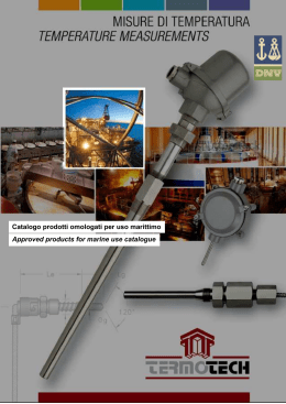
22-11-2010
13:27
Pagina 1
Catalogo prodotti
Products catalogue
TERMOTECH s.r.l.
27029 VIGEVANO (PV) - ITALY
VIA INDIPENDENZA, 58
TEL. +39/0381 347857
FAX +39/0381 341042
www.termotech.com
[email protected]
STUDIO STAND UP - PRINTED IN ITALY - EDIZIONE GENNAIO 2011
Imp_cop_2010
Def_pag_1-16_Termo-2010
22-11-2010
13:46
Pagina 1
MISURE DI TEMPERATURA / TEMPERATURE MEASUREMENTS
L’azienda / The company
p.
2
Tabelle codifiche standard / Standard ordering codes
p.
5
Sezione termoresistenze / Resistance thermometers section
p.
7
- Teoria / Theory
p.
8
- Tabelle / Tables
p.
15
- Prodotti / Products
p.
17
Sezione termocoppie / Thermocouples section
p.
41
- Teoria / Theory
p.
42
- Tabelle / Tables
p.
49
- Prodotti / Products
p.
54
Sezione cavi / Cables section
p.
81
- Teoria / Theory
p.
82
- Prodotti / Products
p.
84
- Tabella colorazioni std / Std colour coding table
p.
88
Sezione pozzetti / Thermowells section
p.
89
- Prodotti / Products
p.
90
Sezione accessori / Accessories section
p.
97
- Connettori compensati / Compensated connectors
p.
98
- Giunti a compressione / Compression fittings
p.
100
- Flange / Flanges
p.
101
- Teste di connessione / Connection heads
p.
102
- Morsettiere ceramiche / Ceramic terminal blocks
p.
105
- Trasmettitori / Transmitters
p.
106
Sommario
Summary
27029 Vigevano (PV) - Italy - via Indipendenza, 58 • tel. +39/0381 347857 - fax +39/0381 341042 • www.termotech.com • [email protected]
1
Def_pag_1-16_Termo-2010
22-11-2010
13:46
Pagina 2
MISURE DI TEMPERATURA / TEMPERATURE MEASUREMENTS
L’Azienda
The Company
La TERMOTECH, nata nel 1990, è specializzata nella progetta-
Founded in 1990, TERMOTECH specializes in the design and
zione e nella costruzione di trasduttori di temperatura elettrici
manufacture of electrical temperature transducers such as
quali termocoppie e termometri a resistenza.
thermocouples and resistance thermometers.
Grazie alla continua ricerca di tecniche produttive innovative e
Continual research into innovative production techniques and
all'utilizzo di componentistica di prima qualità, TERMOTECH si
the use of top quality components make TERMOTECH a relia-
propone come un partner affidabile in grado di fornire un pro-
ble partner whose products offer the best ratio between price
dotto che esprime il meglio come rapporto qualità-prezzo.
and quality.
In particolar modo i prodotti TERMOTECH sono destinati all'in-
TERMOTECH’s products are particularly designed for the food,
dustria alimentare, farmaceutica, chimica, automobilistica e
pharmaceutical, chemical, automobile and plastic materials
delle materie plastiche, nonché in tutti quei settori in cui è
industries, as well as all those sectors where precision, repea-
richiesta: precisione, ripetitività e affidabilità nella misura.
tability and reliability in measurements are required.
TERMOTECH si avvale di un efficiente reparto produttivo con
TERMOTECH has an efficient production department with
personale altamente preparato il quale dispone di moderne
highly qualified personnel and modern equipment to maintain
attrezzature che permettono il mantenimento dei più alti stan-
the highest quality standards.
dard qualitativi.
2
27029 Vigevano (PV) - Italy - via Indipendenza, 58 • tel. +39/0381 347857 - fax +39/0381 341042 • www.termotech.com • [email protected]
Def_pag_1-16_Termo-2010
22-11-2010
13:46
Pagina 3
27029 Vigevano (PV) - Italy - via Indipendenza, 58 • tel. +39/0381 347857 - fax +39/0381 341042 • www.termotech.com • [email protected]
3
Def_pag_1-16_Termo-2010
22-11-2010
13:46
Pagina 4
MISURE DI TEMPERATURA / TEMPERATURE MEASUREMENTS
MISURE DI TEMPERATURA / TEMPERATURE MEASUREMENTs
L’Azienda
The Company
Tutti prodotti TERMOTECH vengono controllati durante e dopo
All TERMOTECH’s products are checked during and after the
il ciclo di lavorazione per verificare che questi rispondano alle
production cycle to ensure that they meet manufacturing spe-
specifiche costruttive; per fare questo TERMOTECH si è dota-
cifications. To do this TERMOTECH has an internal laboratory
ta di un attrezzato laboratorio interno in grado di effettuare tutta
equipped to carry out a series of tests (calibration, checking the
una serie di prove (tarature, verifica della resistenza di isola-
insulation resistance, dielectric strength, etc.) using national
mento, rigidità dielettrica ecc. ecc.) assicurando il riferimento ai
samples as a reference.
campioni nazionali.
TERMOTECH has moreover established an internal quality
TERMOTECH ha inoltre instaurato un sistema di qualità inter-
system certified according to ISO9001:2008 standard, that
no certificato secondo la norma ISO9001:2008 che garantisce
guarantees the perfect correspondence of own products to the
la perfetta rispondenza dei propri prodotti alle caratteristiche
declared futures and to the customer demands.
dichiarate e alle specifiche richieste dal cliente.
For the maritime field, TERMOTECH has obtained the type
Per il settore navale, TERMOTECH, ha ottenuto la certificazio-
approval certification of a product line designed and realized in
ne di tipo di una linea di prodotti appositamente studiata e rea-
order to satisfy the particular robustness need in this field.
lizzata per soddisfare le particolari necessità di robustezza che
TERMOTECH is present both on the Italian and foreign markets
l’applicazione richiede.
with a widespread sales network comprising agents and retai-
TERMOTECH è presente sul mercato italiano ed estero con
lers guaranteeing strong technical and commercial support to
una capillare rete di vendita composta da agenti e rivenditori in
its customers.
grado di garantire un concreto supporto tecnico e commercia-
Our mission is the complete customer satisfaction who is obtai-
le alla propria clientela.
ned supplying always the better product and the better service
La nostra missione è la completa soddisfazione del cliente che
at the better price.
si ottiene fornendo sempre il miglior prodotto ed il miglior ser-
To achieve this we put at disposal: competence, flexibility and
vizio al miglior prezzo.
our experience always proposing the right solution at every
Per il raggiungimento della quale mettiamo a disposizione:
client need.
competenza, flessibilità e la nostra esperienza, proponendo
The range of products listed in this catalogue only covers the
sempre la giusta soluzione ad ogni necessità del cliente.
company’s standard production, however, thanks to its dynamic
La gamma di prodotti riportata su questo catalogo rappresenta
and flexible structure, TERMOTECH is always willing to help
solo la produzione standard, tuttavia, grazie alla propria strut-
customers find the right solution to all temperature measure-
tura dinamica e flessibile, TERMOTECH è costantemente a
ment requirements.
disposizione della clientela per trovare la giusta soluzione ad
ogni problema nella misura della temperatura.
4
27029 Vigevano (PV) - Italy - via Indipendenza, 58 • tel. +39/0381 347857 - fax +39/0381 341042 • www.termotech.com • [email protected]
Def_pag_1-16_Termo-2010
22-11-2010
13:46
Pagina 5
TABELLE CODIFICHE STANDARD / STANDARD ORDERING CODES
Decodifica standard
dei materiali
Decodifica standard dei materiali - Materials standard ordering code
Type of material
Tipo di materiale
Materials standard
ordering code
Codice - Code
AISI 340
304SS
A
AISI 316
316SS
B
AISI 310
310SS
C
AISI 446
446SS
D
Acciaio al carbonio
Carbon steel
E
Acciaio zincato
Galvanized steel
F
Ceramica KER 610
Ceramic KER 610
G
Ceramica KER 710
Ceramic KER 710
H
INCONEL 600
INCONEL 600
I
Hastelloy C
Hastelloy C
J
Ceramica KER 530
Ceramic KER 530
L
Monel
Monel
M
Nicrobel C
Nicrobel C
N
Ottone
Brass
O
Alluminio
Aluminium
P
Rame
Copper
Q
Decodifica standard
range dei convertitori
Decodifica standard range dei convertitori - Standard transmitters range ordering code
Inizio scala (°C)
Start range (°C)
Codice - Code
Fine scala (°C)
End range (°C)
Codice - Code
0
A
+30
0
-10
B
+50
1
-20
C
+70
2
-30
D
+100
3
-40
E
+150
4
-50
F
+200
5
-80
G
+250
6
-100
H
+300
7
-150
I
+350
8
-200
J
+400
9
+450
A
+500
B
+550
C
+600
D
+650
E
+700
F
+750
G
+800
H
+850
I
+900
J
+950
K
+1000
L
+1100
M
+1200
N
+1300
O
+1400
P
+1500
Q
+1600
R
+1700
S
+1800
T
27029 Vigevano (PV) - Italy - via Indipendenza, 58 • tel. +39/0381 347857 - fax +39/0381 341042 • www.termotech.com • [email protected]
Standard transmitters
range ordering code
5
Def_pag_1-16_Termo-2010
22-11-2010
13:46
Pagina 6
TABELLE CODIFICHE STANDARD / STANDARD ORDERING CODES
Decodifica standard e
dimensioni dei filetti
Decodifica standard e dimensioni dei filetti
Standard thread ordering code and dimensions
Standard thread
ordering code
and dimensions
GAS
GAS
METRICO
METRIC
NPT
NPT
Lunghezza “X”(mm)
Length “X” (mm)
Codice - Code
1/8” Maschio
1/8” Male
10
GA
1/4” Maschio
1/4” Male
12
GB
3/8” Maschio
3/8” Male
12
GC
1/2” Maschio
1/2” Male
14
GD
3/4” Maschio
3/4” Male
14
GE
1” Maschio
1” Male
20
GF
1/8” Femmina
1/8” Female
10
G1
1/4” Femmina
1/4” Female
12
G2
3/8” Femmina
3/8” Female
12
G3
1/2” Femmina
1/2” Female
14
G4
3/4” Femmina
3/4” Female
14
G5
M4
M4
6
MA
M5
M5
6
MB
M6
M6
6
MC
M8
M8
6
MD
M10
M10
8
MF
M12x1
M12x1
12
MI
M12x1,5
M12x1,5
12
ML
M12x1,75
M12x1,75
12
MM
M14x1,5
M14x1,5
12
MN
M18x1,5
M18x1,5
14
MO
M20x1,5
M20x1,5
14
MP
M24x1,5
M24x1,5
14
MQ
M27x2
M27x2
14
MR
M33x2
M33x2
14
MS
1/8” Maschio
1/8” Male
4
NA
1/4” Maschio
1/4” Male
6
NB
3/8” Maschio
3/8” Male
6
NC
1/2” Maschio
1/2” Male
8
ND
3/4” Maschio
3/4” Male
8,5
NE
1” Maschio
1” Male
10
NF
GAS - METRICO
GAS - METRIC
6
Thread
Filetto
NPT
NPT
27029 Vigevano (PV) - Italy - via Indipendenza, 58 • tel. +39/0381 347857 - fax +39/0381 341042 • www.termotech.com • [email protected]
Def_pag_1-16_Termo-2010
22-11-2010
13:46
Pagina 7
TERMORESISTENZE
RESISTANCE THERMOMETERS
7
Def_pag_1-16_Termo-2010
22-11-2010
13:46
Pagina 8
TERMORESISTENZE / RESISTANCE THERMOMETERS
Principio
di funzionamento
The working principle for metaI resistance thermometers, normally called thermoresistances, is bases on the variation of the
electrical resistance of a metal with variations in the surrounding temperature.
In the industrial field the materials most frequently used are
platinum and nickel which, due to their high resistivity and stability, permit the production of thermoelements which are
highly reproducible, small and with excellent dynamic characteristics.
The temperature measurements carried out with thermoresistances are far more precise and reliable than those carried out
with other types of sensor such as thermocouples or thermomistors.
Normally resistance thermometers are identified with the code
of the material used to construct them (platinum = Pt, nickel =
Ni etc.) followed by their nominal resistance at a temperature
of 0°C .
The range of use of industrial resistance thermometers is between -200 e +850°C as given in the table.
(ohm)
Working principle
Il principio di funzionamento dei termometri a resistenza metallici, più comunemente chiamati termoresistenze, si basa sulla
variazione della resistenza elettrica di un metallo al variare della
temperatura a cui è sottoposto.
Nel campo industriale i materiali maggiormente utilizzati sono
il platino ed il nichel che, grazie alla loro elevata resistività
e stabilità, permettono di realizzare termoelementi molto riproducibili, di piccole dimensioni e con ottime caratteristiche dinamiche.
Le misure di temperatura effettuate con le termoresistenze sono
di gran lunga più precise e affidabili rispetto a quelle effettuate
con altri tipi di sensori quali termocoppie o termistori.
Normalmente i termometri a resistenza vengono identificati con
la sigla del materiale utilizzato per la loro costruzione (platino =
Pt, Nichel = Ni ecc. ) seguito dalla loro resistenza nominale alla
temperatura di 0°C .
Il campo di utilizzo dei termometri a resistenza industriali è
compreso tra -200 e +850°C come riportato nella tabella.
0
300
10
10
0
Pt
Ni
200
100
0
-400
Termometri a resistenza
di platino (Pt)
Platinum (Pt) resistance
thermometers
8
-200
0
200
Lo standard utilizzato da TERMOTECH per la costruzione dei
termometri a resistenza di platino è riferito alla norma internazionale EN 60751; a richiesta è possibile fornire elementi sensibili conformi ad altri standard quali ad esempio JIS C 1604
ecc.
Secondo lo standard EN 60751 per la costruzione dei termometri a resistenza è previsto l’utilizzo di platino con coefficiente di temperatura α = 3,851x10-3
La normativa EN 60751 prevede termoresistenze con valore
nominale a 0 °C (R0) compreso tra 5 e 1000 ohm; tuttavia i
valori più comunemente utilizzati sono 100 ohm, 500 ohm e
1000 ohm.
400
600
800
(C)
TERMOTECH manufactures platinum resistance thermometers
which comply with the international standard EN 60751; sensitive elements which conform to other standards, for example
JIS C 1604 etc., may be supplied on request.
According to standard EN 60751 the platinum used for the
manufacture of resistance thermometers should have a temperature coefficient α = 3,851x10-3
Standard EN 60751 allows for thermoresistances with a nominal value at 0 °C (Ro) of between 5 and 1000 ohm; however,
the values most commonly used are 100 ohm, 500 ohm and
1000 ohm.
27029 Vigevano (PV) - Italy - via Indipendenza, 58 • tel. +39/0381 347857 - fax +39/0381 341042 • www.termotech.com • [email protected]
Def_pag_1-16_Termo-2010
22-11-2010
13:46
Pagina 9
TERMORESISTENZE / RESISTANCE THERMOMETERS
La relazione che lega la resistenza alla temperatura t° (Rt) e la
resistenza a 0° (R0) è la seguente:
The equation linking resistance at temperature t° (Rt) and resistance at 0° (R0) is a follows:
nel campo -200°C / 0°C
Rt = Ro* [ 1+At+Bt 2+C*(t-100) t 3 ]
in the range -200°C / 0°C
Rt = Ro* [ 1+At+Bt 2+C*(t-100) t 3 ]
nel campo 0°C / 850°C
Rt = Ro* (1+At+Bt 2)
in the range 0°C / 850°C
Rt = Ro* (1+At+Bt 2)
Dove i coefficienti A, B e C valgono:
A = 3,9083 x 10⁻³
B = -5,775 x 10-7
C = -4,183 x 10-12
Where the coefficients A, B and C have the following values:
A = 3.9083 x 10⁻³
B = -5.775 x 10⁻⁷
C = -4.183 x 10⁻¹²
Le classi di precisione dei termometri a resistenza di platino
sono riferite alla temperatura e sono così normalizzati:
The classes of precision for platinum resistance thermometers
refer to temperature and are standardized as follows:
Classe AA = 0,1 + 0,0017* | t | (°C)
Classe A = 0,15 + 0,002* | t | (°C )
Classe B = 0,3 + 0,005* | t | (°C )
Classe C = 0,6 + 0,01* | t | (°C)
Classe AA = 0,1 + 0,0017* | t | (°C)
Classe A = 0,15 + 0,002* | t | (°C )
Classe B = 0,3 + 0,005* | t | (°C )
Classe C = 0,6 + 0,01* | t | (°C)
Gli intervalli di temperatura di validità delle classi di tolleranza
sopra esposte sono riportati nella tabella di pagina 16. Tutti i
termometri a resistenza con classe di tolleranza superiore alla
B devono avere una configurazione a tre o quattro fili.
The temperature ranges of validity of the tolerance classes
above mentioned are reported in the table of page 16. All the
resistance thermometers of tolerance class better then class B
shall have three or four wire configuration.
I termometri a resistenza di nichel sono normalizzati dalla
norma tedesca DIN 43760.
A differenza del platino, il nichel ha un coefficiente di temperatura superiore (α = 6,17 x 10⁻³ ) che, sopperendo alla sua
minore resistività elettrica, ne rende la sensibilità paragonabile
a quella delle termoresistenze in platino.
La scarsa resistenza all’ossidazione limita il campo di impiego
dei termometri a resistenza di nichel nel campo di temperatura compreso tra -100°C e +200°C.
La relazione che lega la resistenza alla temperatura t° (Rt) e la
resistenza a 0° (R0) è la seguente:
Nickel resistance thermometers are standardized by the
German Standard DIN 43760.
As opposed to platinum, nickel has a higher temperature coefficient (α = 6,17 x 10⁻³) which, compensating for its lower electrical resistivity, makes its sensitivity comparable to that of platinum thermoresistances.
Their poor resistance to oxidation limits the range of use of nickel resistance thermometers to temperatures between -100°C
e +200°C.
The equation linking resistance at temperature t° (Rt) and the
resistance at 0° (R0) is as follows:
nel campo -60°C / +180°C
Rt = Ro* (1+ At + Bt 2 + Ct 4)
in the range -60°C / +180°C
Rt = Ro* (1+ At + Bt 2 + Ct 4)
Dove i coefficienti A, B e C valgono:
A = 5,485 x 10-3
B = 6,650 x 10-6
C = 2,805 x 10-11
Where the coefficients A, B and C have a value of:
A = 5,485 x 10-3
B = 6,650 x 10-6
C = 2,805 x 10-11
È normalizzata una sola classe di precisione per i termometri a
resistenza di nichel che è riferita alla temperatura:
There is only one class of precision for nickel resistance thermometers in the standard which refers to temperature:
Nel campo -60°C / 0°C: 0,4 + 0,028* | t | (°C)
Nel campo 0°C / 180°C: 0,4 + 0,007* | t | (°C)
In the range -60°C / 0°C: 0,4 + 0.028* | t | (°C)
In the range 0°C / 180°C: 0,4 + 0.007* | t | (°C)
27029 Vigevano (PV) - Italy - via Indipendenza, 58 • tel. +39/0381 347857 - fax +39/0381 341042 • www.termotech.com • [email protected]
Termometri a resistenza
di Nichel
Nickel resistance
thermometers
9
Def_pag_1-16_Termo-2010
22-11-2010
13:46
Pagina 10
TERMORESISTENZE / RESISTANCE THERMOMETERS
Metodi di misura con i
termometri a resistenza
Measuring methods
for resistances
thermometers
Esistono diversi metodi di collegamento dei termometri a resistenza con gli apparecchi di misura, la scelta di utilizzo di un
metodo rispetto ad un altro dipende essenzialmente dalla precisione nella misura che si vuole ottenere.
There are different methods for connecting the resistance thermometers to the measuring devices, the choice of one method
rather than another basically depends on the precision required in the measurement.
RED
RED
RED
RED
RED
1 x RTD
WHITE
WHITE
WHITE
WHITE
RED
RED
RED
RED
RED
WHITE
WHITE
WHITE
WHITE
YELLOW
YELLOW
YELLOW
BLACK (Grey)
BLACK (Grey)
YELLOW
BLACK (Grey)
BLACK (Grey)
2 x RTD
BLACK (Grey)
PT100-2
(a)
PT100-4
(c)
Tecniche di collegamento delle termoresistenze:
Type of connection for resistance thermometer:
(a) A 2 fili
(a) 2 - wires
(b) A 3 fili
(b) 3 - wires
(c) A 4 fili volt-amperometrica
(c) 4 - wires volt-ammeter
La tecnica a due fili è la meno precisa e viene utilizzata solo nei
casi in cui il collegamento della termoresistenza viene effettuato con fili di lunghezza ridotta e con bassa resistività; infatti
esaminando il circuito elettrico equivalente, si nota come la
resistenza elettrica misurata sia la somma di quella dell’elemento sensibile (e quindi dipendente dalla temperatura che si
sta misurando) e della resistenza dei conduttori utilizzati per il
collegamento.
L’errore introdotto con questo tipo di misura non è costante ma
dipende dalla temperatura.
The two-wire technique is the least precise and is used only in
cases where the connection of the thermoresistance is carried
out with short and low resistivity wires; indeed testing the equivalent electrical circuit, it can be noted that the electrical resistance measured is the sum of that of the sensitive element
(and, therefore, dependent on the temperature being measured) and the resistance of the conductors used for the connection.
The error introduced with this type of measurement is not constant: it depends on temperature.
Collegamento a 2 fili
10
PT100-3
(b)
2 - wires connection
27029 Vigevano (PV) - Italy - via Indipendenza, 58 • tel. +39/0381 347857 - fax +39/0381 341042 • www.termotech.com • [email protected]
Def_pag_1-16_Termo-2010
22-11-2010
13:46
Pagina 11
TERMORESISTENZE / RESISTANCE THERMOMETERS
Grazie alla buona precisione ottenibile nella misura, la tecnica
a tre fili è la più utilizzata in campo industriale.
Con questa tecnica di misura infatti vengono eliminati gli errori provocati dalla resistenza dei conduttori impiegati per il collegamento della termoresistenza; infatti all’uscita del ponte di
misura è presente una tensione dipendente unicamente dalla
variazione della resistenza del termometro a resistenza e quindi dalla sola temperatura.
Due to the good degree of precision obtainable in measurements, the three-wire technique is the most used in the industrial field.
With this measurement technique the errors caused by the
resistance of the conductors used for the connection of the
thermoresistance are eliminated; at the output of the measuring bridge the voltage present depends entirely on the variation of the resistance of the resistance thermometer and consequently only on the temperature.
3 - wires connection
Collegamento a 3 fili
La tecnica a quattro fili volt-amperometrica fornisce la migliore
precisione possibile in senso assoluto; poco utilizzata nel
campo industriale, viene utilizzata quasi esclusivamente nelle
applicazioni di laboratorio.
Dal circuito elettrico equivalente si nota come la tensione rilevata sia unicamente dipendente dalla resistenza del termoelemento; la precisione nella misura dipende esclusivamente dalla
stabilità della corrente di misura e dalla precisione della lettura
della tensione ai capi del termoelemento.
The volt-ammeter four-wire technique offers the greatest precision possible; little used in the industrial field, it is almost
exclusively used in laboratory applications.
On an equivalent electrical circuit it can be seen that the voltage measured depends solely on the resistance of the thermoelement; the precision of the measurement depends exclusively
on the stability of the measuring current and the precision of
the voltage reading across the thermoelement.
Volt-ammeter
4 - wires connection
Collegamento a 4 fili
volt-amperometrica
Esistono due tipologie costruttive per la termoresistenze: ad
isolamento tradizionale o ad isolamento minerale MgO.
La tabella seguente mostra le principali caratteristiche delle
due tipologie:
Velocità
di risposta
There are two construction types of thermoresistances: with
traditional insulation or mineral MgO insulation.
The following table shows the main characteristics of the two
types:
Isolamento
Resistenza
Resistenza
elettrico alle vibrazioni alle pressioni
Response
speed
Electrical
insulation
Vibration
Resistance
Pressure
Resistance
Isolamento
tradizionale
Buono
Ottimo
Buono
Buono
Traditional
insulation
Good
Excellent
Good
Good
Isolamento
minerale (MgO)
Ottimo
Buono
Ottimo
Ottimo
Mineral (MgO)
insulation
Excellent
Good
Excellent
Excellent
27029 Vigevano (PV) - Italy - via Indipendenza, 58 • tel. +39/0381 347857 - fax +39/0381 341042 • www.termotech.com • [email protected]
Costruzione dei
termometri a resistenza
Construction of
resistance
thermometers
11
Def_pag_1-16_Termo-2010
22-11-2010
13:46
Pagina 12
TERMORESISTENZE / RESISTANCE THERMOMETERS
Termoresistenze ad
isolamento tradizionale
Le termoresistenze con isolamento tradizionale sono costituite da:
Traditional insulation thermoresistances comprise:
Traditional insulation
thermoresistances
1 - Elemento sensibile
L’elemento sensibile è la parte più importante di tutto l’assieme, un elemento sensibile di scarsa qualità pregiudica il corretto funzionamento dell’intero sensore. Questo, una volta connesso con i fili di collegamento, viene posto all’interno della
guaina di protezione.
Sono disponibili elementi sensibili di diversa precisione e con
doppio avvolgimento.
1 - sensitive element
The sensitive element is the most important part of the thermoresistance, a poor quality sensitive element would jeopardize
the correct functioning of the entire sensor. Once connected
with the connection wires, it is placed inside the protective
sheath.
Sensitive elements with different degrees of precision and with
double winding are available.
2 - Fili di collegamento
Il collegamento dell’elemento sensibile può essere effettuato a
2, 3 o 4-fili, il materiale degli stessi dipende dalle condizioni di
impiego della sonda.
2 - Connection wires
The connection of the sensitive element can be carried out
using 2, 3 or 4 wires; the wire material depends on the conditions of use of the probe.
3 - Isolatori ceramici
Gli isolatori ceramici servono a prevenire corti circuiti e isolano
i fili di collegamento dalla guaina di protezione.
3 - Ceramic insulator
Ceramic insulators prevent short circuits and insulate the connection wires from the protective sheath.
4 - Riempitivo
Il riempitivo è composto da polvere di allumina finissima, essiccata e vibrata, la quale va a riempire qualunque interstizio proteggendo quindi il sensore dalle vibrazioni.
4 - Filler
The filler is composed of extremely fine alumina powder, dried
and vibrated, which fills any gaps so as to protect the sensor
from vibrations.
5 - Guaina di protezione
La guaina di protezione serve per proteggere l’elemento sensibile e fili di
collegamento. Essendo a diretto contatto con il processo è importante che
questa sia costituita dal giusto materiale e abbia le giuste dimensioni.
In condizioni particolari è bene ricoprire la stessa con una ulteriore protezione ( pozzetto termometrico).
6 - Testa di connessione
La testa di connessione contiene una
morsettiera di materiale isolante (normalmente ceramica) che permette il
collegamento elettrico della termoresistenza; in funzione delle condizioni di
impiego possono essere usate custodie antideflagranti.
Al posto della morsettiere è possibile
installare un convertitore con uscita
4-20 mA.
6
2
5
4
5 - Protective sheath
The protective sheath protects the
sensitive element and the connection
wires. Since it is in direct contact with
the process it is important that it is
made of the right material and has the
right dimensions.
In certain conditions it is advisable to
cover the sheath with additional
casing (thermowell).
6 - Connection head
The connection head contains the terminal board made of insulating material (normally ceramic) which permits
the electrical connection of the thermoresistance. Depending on the conditions of use explosionproof casing
may be used.
A 4-20 mA converter can be installed
instead of the terminal board.
3
1
12
27029 Vigevano (PV) - Italy - via Indipendenza, 58 • tel. +39/0381 347857 - fax +39/0381 341042 • www.termotech.com • [email protected]
Def_pag_1-16_Termo-2010
22-11-2010
13:46
Pagina 13
TERMORESISTENZE / RESISTANCE THERMOMETERS
Questa particolare tipologia costruttiva permette di realizzare
termoresistenze di elevate prestazioni e con caratteristiche
meccaniche eccellenti.
Caratteristiche principali che differenziano questo tipo di
costruzione, oltre a quelle già descritte, da quello tradizionale
sono: la possibilità di piegare la guaina con raggi di curvatura
molto ridotti, la possibilità di saldare la guaina al momento dell'installazione e la possibilità di realizzare sonde molto lunghe.
1 - Elemento sensibile
Con l’utilizzo di particolari tecniche, l’elemento sensibile viene
collegato ai conduttori del cavo isolato in ossido minerale.
In funzione delle diverse esigenze è possibile l’utilizzo di elementi sensibili doppi e/o con diverse precisioni.
2 - Fili di collegamento
Il collegamento dell’elemento sensibile può essere effettuato a
2, 3 o 4-fili.
3 - Guaina con isolamento minerale
Questa è composta da una guaina metallica esterna con all’interno i conduttori isolati tra loro e dalla guaina per mezzo di
ossidi metallici purissimi e altamente compressi; l’isolamento
standard è l’ossido di magnesio
(MgO).
4 - Testa di connessione
La testa di connessione contiene una
morsettiera in materiale isolante (normalmente ceramica) che permette il
collegamento elettrico della termoresistenza; in funzione delle condizioni di
impiego possono essere utilizzate
custodie antideflagranti.
Al posto della morsettiera è possibile
installare un convertitore con uscita
4-20 mA.
4
2
This particular construction type permits the manufacture of
high performance thermoresistances with excellent mechanical
characteristics.
The main characteristics which differentiate this type of construction from the traditional type, in addition to those already
described, are: the possibility of bending the sheath with a
sharp bending radius, the possibility of soldering the sheath
upon installation and the possibility of creating very long
probes.
Termoresistenze ad
isolamento
minerale MgO
Mineral MgO
insulation
thermoresistances
1 - Sensitive element
With the use of particular techniques, the sensitive element is
connected to the conductors of the cable insulated in mineral
oxide.
To meet different requirements, it is possible to use double
sensitive elements or elements with different degrees of precision.
2 - Connection wires
The sensitive element can be connected using 2, 3 or 4 wires.
3 - Mineral insulation sheath
This comprises an external metal sheath with the conductors
insulated inside from one another and
the sheath using extremely pure and
highly compressed metal oxides; the
standard insulator is magnesium oxide
(MgO).
4 - Connection head
The connection head contains the terminal board made of insulating material (normally ceramic) which permits
the electrical connection of the thermoresistance. Depending on the conditions of use explosionproof casing
may be used.
A 4-20 mA converter can be installed
instead of the terminal board.
3
1
27029 Vigevano (PV) - Italy - via Indipendenza, 58 • tel. +39/0381 347857 - fax +39/0381 341042 • www.termotech.com • [email protected]
13
Def_pag_1-16_Termo-2010
22-11-2010
13:46
Pagina 14
TERMORESISTENZE / RESISTANCE THERMOMETERS
Principali cause
di errore nelle misure
con termoresistenze
The main causes
of errors
in measurements with
thermoresistances
La misura della temperatura con le termoresistenze è abbastanza semplice da eseguire rispetto a quella fatta con altri tipi
di sensori tuttavia è opportuno fare attenzione ad alcuni accorgimenti in modo da ovviare ad eventuali errori nella misura.
Le principali cause di errore che si introducono nella misura
della temperatura con le termoresistenze sono tre:
- Errore dovuto all’autoriscaldamento dell’elemento sensibile
- Errore dovuto allo scarso isolamento elettrico dell’elemento
sensibile
- Errore dovuto alla non sufficiente profondità di immersione
dell’elemento sensibile.
Measuring temperature with thermoresistances is quite simple
to carry out compared to that using other types of sensors,
however certain steps should be taken to remedy any measurement errors.
There are three main causes of errors introduced into temperature measurements with thermoresistances:
- Error due to the selfheating of the sensing element
- Error due to the poor electrical insulation of the sensitive element
- Error due to the sensitive element not being immersed at sufficient depth.
L’autoriscaldamento dell’elemento sensibile si ha, in fase di
misura, quando questo viene attraversato da una corrente
troppo elevata che, per l’effetto Joule, ne fà aumentare la
temperatura.
Questo innalzamento della temperatura è dipendente sia dal
tipo di elemento sensibile utilizzato che dalle condizioni di
misura; infatti la stessa termoresistenza, a parità di temperatura, si auto riscalderà meno se viene posta in acqua piuttosto
che in aria; questo è dovuto al fatto che l’acqua ha un coefficiente di dissipazione più elevato rispetto all’aria.
Normalmente tutti gli apparecchi di misura che utilizzano come
sensore delle termoresistenze hanno una corrente di misura
molto bassa tuttavia è buona norma non superare mai la corrente di misura di 1 mA (EN 60751).
The sensitive element heats up by itself during measuring
when it is crossed by a current which is too high which, due to
the Joule effect, increases the temperature of the element.
The increase in temperature depends both on the type of sensitive element used and the measuring conditions. At the same
temperature, the same thermoresistance will heat up by itself
less if placed in water rather than air; this is due to the fact that
water has a higher dispersion coefficient than air.
Normally all measuring devices which use thermoresistances
as sensors have an extremely low measuring current, however
it is advisable never to exceed a measuring current of 1 mA (EN
60751).
Per una buona misura con le termoresistenze è molto importante che l’isolamento elettrico tra i conduttori e la guaina
esterna sia adeguatamente elevato soprattutto alle alte temperature.
La resistenza di isolamento può essere vista come una resistenza elettrica posta in parallelo a quelle dell’elemento sensibile, risulta quindi evidente come, a temperatura costante, nel
caso in cui l’isolamento elettrico diminuisca, anche la tensione
rilevata ai capi dell’elemento sensibile diminuirà introducendo
quindi un errore nella misura.
L’abbassamento della resistenza di isolamento può verificarsi
per l’utilizzo della sonda con temperature troppo elevate, in
presenza di forti vibrazioni o per l’influenza di agenti fisici o
chimici.
Particolarmente importante per una buona misura è anche la
profondità di immersione dell’elemento sensibile; questa, a
differenza che per le termocoppie la cui misura può considerarsi puntiforme, se non è adeguata, può arrecare errori nella
misura anche nell’ordine parecchi gradi °C.
Questo è dovuto al fatto che la guaina, solitamente metallica,
con cui viene protetto l’elemento sensibile dissipa calore in
maniera proporzionale alla differenza di temperatura presente
tra la zona calda e quella fredda; si è quindi in presenza di un
gradiente termico su parte della lunghezza della guaina.
La profondità di immersione dovrà quindi essere sufficiente per
fare in modo che l’elemento sensibile posto all’interno della
guaina, non sia sottoposto a questo gradiente termico.
Tale profondità minima dipenderà sia dalle condizioni fisiche di
misura che dalle dimensioni della termoresistenza (lunghezza
dell’elemento ecc.).
14
For the correct measurement with thermoresistances it is very
important that the electrical insulation between the conductors
and the external sheath is sufficiently great, particularly at high
temperatures.
The insulation resistance may be seen as an electrical resistance positioned parallel to those of the sensitive element. It is,
therefore, clear how, at a constant temperature, should the
electrical insulation diminish, the voltage measured across the
sensitive element will also diminish thus introducing an error
into the measurement.
Insulation resistance can fall when the probe is used at temperatures which are too high, when there are strong vibrations or
because of the influence of physical or chemical agents.
The immersion depth of the sensitive element is also extremely important for correct measurements; unlike in thermocouples where measurements can be considered punctiform, if the
depth is not sufficient it can cause errors in the measurement
of as much as several degrees °C.
This is due to the fact that the sheath, usually metallic, with
which the sensitive element is protected disperses heat in proportion to the difference in temperature between the hot and
cold areas; we, therefore, have a thermal gradient along part of
the sheath’s length.
The immersion depth must, therefore, be sufficient so that the
sensitive element inside the sheath is not subjected to this
thermal gradient.
The minimum depth will depend on the physical measuring
conditions and the dimensions of the thermoresistance (length
of the element etc.).
27029 Vigevano (PV) - Italy - via Indipendenza, 58 • tel. +39/0381 347857 - fax +39/0381 341042 • www.termotech.com • [email protected]
Def_pag_1-16_Termo-2010
22-11-2010
13:46
Pagina 15
TERMORESISTENZE / RESISTANCE THERMOMETERS
Tabelle di riferimento
Reference tables
°C
0
-10
-20
-30
-40
-50
-60
-70
-80
-90
Ohm - Ohm
0
°C
100,00
94,6
89,3
84,2
79,1
74,3
69,5
0
10
20
30
40
50
60
70
80
90
154,9
Ohm - Ohm
0
100,0
105,6
111,2
117,1
123,0
123,0
135,3
141,7
148,3
100
161,8
168,8
176,0
183,3
190,9
190,9
206,6
214,8
223,2
0
-10
-20
-30
-40
-50
-60
-70
-80
-90
°C
Ohm - Ohm
-200
18,49
14,45
10,49
6,99
4,26
2,51
-100
60,26
56,19
52,11
48,00
43,88
39,72
35,54
31,34
27,10
22,83
0
100,00
96,09
92,16
88,22
84,27
80,31
76,33
72,33
68,33
64,30
0
10
20
30
40
50
60
70
80
90
°C
Ohm - Ohm
0
100,00
103,90
107,79
111,67
115,54
119,40
123,24
127,08
130,90
134,71
100
138,51
142,29
146,07
149,83
153,58
157,33
161,05
164,77
168,48
172,17
200
175,86
179,53
183,19
186,84
190,47
194,10
197,71
201,31
204,90
208,48
300
212,05
215,61
219,15
222,68
226,21
229,72
233,21
236,70
240,18
243,64
400
247,09
250,53
253,96
257,38
260,78
264,18
267,56
270,93
274,29
277,64
500
280,98
284,30
287,62
290,92
294,21
297,49
300,75
304,01
307,25
310,49
600
313,71
316,92
320,12
323,30
326,48
329,64
332,79
335,93
339,06
342,18
700
345,28
348,38
351,46
354,53
357,59
360,64
363,67
366,70
369,71
372,71
800
375,70
378,68
381,65
384,60
387,55
390,48
27029 Vigevano (PV) - Italy - via Indipendenza, 58 • tel. +39/0381 347857 - fax +39/0381 341042 • www.termotech.com • [email protected]
Termoresistenza
tipo NI100
ohm 0°C secondo
DIN 43760 (IPTS 68)
Resistance
thermometer
type NI100
ohm 0°C acc. to
DIN 43760 (IPTS 68)
Termoresistenza
tipo PT100
ohm 0°C secondo
EN 60751
Resistance
thermometer
type PT100
ohm 0°C
EN 60751
15
Def_pag_1-16_Termo-2010
22-11-2010
13:46
Pagina 16
TERMORESISTENZE / RESISTANCE THERMOMETERS
Tolleranze standard
per i termometri
a resistenza
Standard accuracy
for resistance
thermoresistances
Termoresistenza
tipo PT100
ohm 0°C (EN 60751)
Resistance
thermometer
type PT100
ohm 0°C (EN 60751)
Intervallo di temperatura di validità
Temperature range of validity
°C
Classe di tolleranza
Tolerence class
Resistori a filo avvolto
Wire wound resistors
Resitori a film
Film resistors
AA
-50 ÷ +250
0 ÷ +150
± (0,1 + 0,0017* | t |)
A
-100 ÷ +450
-30 ÷ +300
± (0,15 + 0,002* | t |)
B
-196 ÷ +600
-50 ÷ +500
± (0,3 + 0,005* | t |)
C
-196 ÷ +600
-50 ÷ +600
± (0,6 + 0,01* | t |)
| t | = Moduls of temperature in °C without regards to the sign
| t | = valore assoluto della temperatura, espresso in °C,
indipendente dal segno
Possono essere definite anche classi di tolleranza speciali per intervalli
di temperature estesi o limitati.
Termoresistenza
tipo NI100
ohm 0°C (DIN 43760)
Resistance
thermometer
type NI100
ohm 0°C (DIN 43760)
Temp. °C
Special tolerance classes may also be defined for extended or restricted
temperature ranger.
0,4+0,07*| t | (°C) 0°C<t<180°C
0,4+0,028*| t | (°C) -60°C<t<0°C
Ohm
°C
-60
±1,00
±2,10
0
±0,20
±0,40
100
±0,80
±1,10
180
±1,30
±1,70
t = Temperatura °C
16
Valori di tolleranza
Tolerance values
°C
t = Temperature °C
27029 Vigevano (PV) - Italy - via Indipendenza, 58 • tel. +39/0381 347857 - fax +39/0381 341042 • www.termotech.com • [email protected]
Def_pag_17-32_Termo-2010
26-11-2010
16:06
Pagina 1
TERMORESISTENZE / RESISTANCE THERMOMETERS
Termoresistenza portatile per misure generiche e di
laboratorio, disponibile in esecuzione per misure di
contatto, per immersione e per penetrazione.
La sonda è dotata di una impugnatura in P.V.C. caricato vetro e di cavo.
Disponibile con svariati tipi connettori in modo da
essere collegabile a molti termometri palmari.
Portable resistance thermometer for generical and
laboratories measurements, available for surface,
immersion and penetration measurements.
The probe have a glass filled plastic handle and an
extension cable.
Are also availables a lot of connectors to be able to
be connectable with several portable thermometers.
Diagramma della precisione
Precision diagram
RPI
Caratteristiche tecniche
- Temperatura di funzionamento parte sensibile:
-80+250°C
- Temperatura di funzionamento impugnatura:
-40+105°C
- Precisione(1): Secondo EN60751 classe A, B o AA
- Grado di protezione: IP65
- Materiale guaina: AISI 316
Technical Features
- Operating temperature: -80+250°C
- Handle operating temperature: -40+105°C
- Accuracy (1): According to EN60751 class A, B or AA
- Protection degree: IP65
- Stem material: AISI 316
NOTA:
(1)
Gli intervalli di temperatura di validità delle classi di
tolleranza sono riportati nella tabella a pag. 16
NOTE:
(1)
The temperature ranges of validity of tolerance classes
are reported in the table at page 16
Schema connessioni
Connection diagram
Tabella codifica
Ordering code
RPI
TYPE
P = Penetration
I = Immersion
C = Contact
TIPO
P = Penetrazione
I = Immersione
C = Contatto
TERMINAZIONE
- = Standard
F = Faston
P = Puntalini
TERMINATION
- = Standard
F = Faston
P = Split leads
NUMBER OF SENSING ELEMENTS
1 = Simple
NUMERO ELEMENTI SENSIBILI
1 = Semplice
LUNGHEZZA CAVO Lc
Da specificare in dm
CABLE LENGTH Lc
To be specified in dm
TYPE OF SENSOR
P = PT 100
1 = PT 1000
Y = PTC 1 Kohm 25°C
C = NTC 10 Kohm 25°C
TIPO DI SENSORE
P = PT 100
1 = PT 1000
Y = PTC 1 Kohm 25°C
C = NTC 10 Kohm 25°C
TIPO DI CAVO
B = G-G (-40 +200 °C)
P = P-P (-20 +80 °C)
Z = Cavo spiralato L=1500 mm
TYPE OF CABLE
B = G-G (-40 +200 °C)
P = P-P (-20 +80 °C)
Z = Spiralized cable L=1500 mm
CONNECTION
2 = 2-wires
3 = 3-wires
4 = 4-wires
COLLEGAMENTO
2 = A 2-fili
3 = A 3-fili
4 = A 4-fili
LUNGHEZZA GUAINA Lg
100 = 100 mm
150 = 150 mm
200 = 200 mm
STEM LENGTH Lg
100 = 100 mm
150 = 150 mm
200 = 200 mm
ACCURACY (1)
A = According to EN60751 class A
B = According to EN60751 class B
3 = According to EN60751 class AA
L = 1% (sensor type Y or C)
PRECISIONE(1)
A = Secondo EN60751 classe A
B = Secondo EN60751 classe B
3 = Secondo EN60751 classe AA
L = 1% (sensore tipo Y e C)
DIAMETRO GUAINA Øg
(solo tipo I e P)
- = Per tipo C
3 = Ø 3 mm
4 = Ø 4 mm
6 = Ø 6 mm
STEM DIAMETER Øg
(only for type I and P)
- = For type C
3 = Ø 3 mm
4 = Ø 4 mm
6 = Ø 6 mm
27029 Vigevano (PV) - Italy - via Indipendenza, 58 • tel. +39/0381 347857 - fax +39/0381 341042 • www.termotech.com • [email protected]
17
Def_pag_17-32_Termo-2010
26-11-2010
16:06
Pagina 2
TERMORESISTENZE / RESISTANCE THERMOMETERS
RLM
Caratteristiche tecniche
- Temperatura di funzionamento: In funzione del tipo
di cavo
- Precisione(1): Secondo EN60751 classe A, B o AA
Technical Features
- Operating temperature: Depending on the cable type
- Accuracy (1): According to EN60751 class A, B or AA
NOTA:
(1)
Gli intervalli di temperatura di validità delle classi di
tolleranza sono riportati nella tabella a pag. 16
NOTE:
(1)
The temperature ranges of validity of tolerance classes
are reported in the table at page 16
Schema connessioni
Tabella codifica
Connection diagram
Termoresistenza cilindrica con guaina in acciaio
inox AISI 304 adatta per misure e regolazioni
generiche.
L'uscita del cavo dalla guaina è protetto da una
molla in acciaio inox.
All’interno della guaina possono essere alloggiati
uno o due elementi sensibili il cui collegamento
può essere a 2, 3 o 4 fili (solo con un elemento
sensibile).
Cylindrical resistance thermometer with AISI 304
sheath suitable for generical measurements and
regulations.
The output of the cable from the tube is protected
with a stainless steeel spring.
It is possible to have one or two sensing elements
fitted inside the protective tube with 2,3 or 4-wires
(only available with one sensing element) connection.
Diagramma della precisione
Precision diagram
Ordering code
RLM
18
NUMBER OF SENSING ELEMENTS
1 = Simple
2 = Double
NUMERO ELEMENTI SENSIBILI
1 = Semplice
2 = Doppio
TYPE OF SENSOR
P = PT 100
1 = PT 1000
N = NI 100
Y = PTC 1 Kohm 25°C
C = NTC 10 Kohm 25°C
TIPO DI SENSORE
P = PT 100
1 = PT 1000
N = NI 100
Y = PTC 1 Kohm 25°C
C = NTC 10 Kohm 25°C
CONNECTION
2 = 2-wires
3 = 3-wires
4 = 4-wires
COLLEGAMENTO
2 = A 2-fili
3 = A 3-fili
4 = A 4-fili
ACCURACY (1)
A = According to EN60751 class A
B = According to EN60751 class B
3 = According to EN60751 class AA
L = 1% (sensor type Y or C)
PRECISIONE(1)
A = Secondo EN60751 classe A
B = Secondo EN60751 classe B
3 = Secondo EN60751 classe AA
L = 1% (sensore tipo Y e C)
TERMINAZIONE
- = Standard
F = Faston
P = Puntalini
TERMINATION
- = Standard
F = Faston
P = Split leads
LUNGHEZZA CAVO Lc
Da specificare in dm
CABLE LENGTH Lc
To be specified in dm
TIPO DI CAVO
A = T-T-S (0-400°C)
B = G-G (-40+200°C)
C = G-G-S (-40+200°C)
E = F-S-F (-50+240°C)
P = P-P (-20+105°C)
TYPE OF CABLE
A = T-T-S (0-400°C)
B = G-G (-40+200°C)
C = G-G-S (-40+200°C)
E = F-S-F (-50+240°C)
P = P-P (-20+105°C)
LUNGHEZZA GUAINA Lg
030 = 30 mm
050 = 50 mm
100 = 100 mm
200 = 200 mm
XXX = Altro
STEM LENGTH Lg
030 = 30 mm
050 = 50 mm
100 = 100 mm
200 = 200 mm
XXX = Special
DIAMETRO GUAINA Øg
4 = Ø 4 mm
6 = Ø 6 mm
8 = Ø 8 mm
X = Altro
STEM DIAMETER Øg
4 = Ø 4 mm
6 = Ø 6 mm
8 = Ø 4 mm
X = Ø 6 mm
27029 Vigevano (PV) - Italy - via Indipendenza, 58 • tel. +39/0381 347857 - fax +39/0381 341042 • www.termotech.com • [email protected]
Def_pag_17-32_Termo-2010
26-11-2010
16:06
Pagina 3
TERMORESISTENZE / RESISTANCE THERMOMETERS
Termoresistenza cilindrica con guaina in acciaio
inox AISI 316 isolata in ossido di magnesio (MgO)
compatto.
La particolare tipologia costruttiva rende questo
tipo di sonda particolarmente indicata in presenza
di forti vibrazioni e/o dove sia richiesta una elevata
velocità di risposta.
La bussola di transizione (entro la quale viene realizzata la connessione tra l'elemento sensibile e
cavo) è in acciaio inox; l'uscita del cavo dalla stessa è protetta da una molla anch'essa in acciaio
inox.
Cylindrical resistance thermometer with AISI 316
sheath insulated with compact magnesium oxide
(MgO).
Due to the particular construction type, this probe is
particulary indicated where are presents high vibrations and where a fast respons time is necessary.
The transition sleeve (where is realized the junction
between the sensing element and the cable) is
made in stainless steel like the protection spring
situated at the cable output.
Diagramma della precisione
Precision diagram
RMM
Caratteristiche tecniche
- Temperatura di funzionamento (parte sensibile):
-80+600°C
- Temperatura di funzionamento bussola di transizione: max. 200°C
- Precisione(1): Secondo EN60751 classe A, B o AA
- Raggio minimo di curvatura parte sensibile: 3 volte
il diametro
Technical Features
- Operating temperature (sensing part): -80+600°C
- Operating temperature (transition sleeve): max
200°C
- Accuracy (1): According to EN60751 class A, B or AA
- Minimum bending radius: 3 times the diameter
NOTA:
(1)
Gli intervalli di temperatura di validità delle classi di
tolleranza sono riportati nella tabella a pag. 16
NOTE:
(1)
The temperature ranges of validity of tolerance classes
are reported in the table at page 16
Schema connessioni
Connection diagram
Tabella codifica
Ordering code
RMM
NUMBER OF SENSING ELEMENTS
1 = Simple
2 = Double
NUMERO ELEMENTI SENSIBILI
1 = Semplice
2 = Doppio
TYPE OF SENSOR
P = PT 100
1 = PT 1000
TIPO DI SENSORE
P = PT 100
1 = PT 1000
CONNECTION
2 = 2-wires
3 = 3-wires
4 = 4-wires
COLLEGAMENTO
2 = A 2-fili
3 = A 3-fili
4 = A 4-fili
ACCURACY (1)
A = According to EN60751 class A
B = According to EN60751 class B
3 = According to EN60751 class AA
PRECISIONE(1)
A = Secondo EN60751 classe A
B = Secondo EN60751 classe B
3 = Secondo EN60751 classe AA
TERMINAZIONE
- = Standard
F = Faston
P = Puntalini
TERMINATION
- = Standard
F = Faston
P = Split leads
LUNGHEZZA CAVO Lc
Da specificare in dm
CABLE LENGTH Lc
To be specified in dm
TIPO DI CAVO
A = T-T-S (0-400°C)
B = G-G (-40+200°C)
C = G-G-S (-40+200°C)
E = F-S-F (-50+240°C)
P = P-P (-20+105°C)
TYPE OF CABLE
A = T-T-S (0-400°C)
B = G-G (-40+200°C)
C = G-G-S (-40+200°C)
E = F-S-F (-50+240°C)
P = P-P (-20+105°C)
LUNGHEZZA GUAINA Lg
050 = 50 mm
100 = 100 mm
150 = 150 mm
200 = 200 mm
XXX = Altro
STEM LENGTH Lg
050 = 50 mm
100 = 100 mm
150 = 150 mm
200 = 200 mm
XXX = Special
DIAMETRO GUAINA Øg
30 = Ø 3 mm
45 = Ø 4,5 mm
60 = Ø 6 mm
STEM DIAMETER Øg
30 = Ø 3 mm
45 = Ø 4,5 mm
60 = Ø 6 mm
27029 Vigevano (PV) - Italy - via Indipendenza, 58 • tel. +39/0381 347857 - fax +39/0381 341042 • www.termotech.com • [email protected]
19
Def_pag_17-32_Termo-2010
26-11-2010
16:06
Pagina 4
TERMORESISTENZE / RESISTANCE THERMOMETERS
RLR
Caratteristiche tecniche
- Temperatura di funzionamento: In funzione del tipo
di cavo
- Precisione(1): Secondo EN60751 classe A, B o AA
Technical Features
- Operating temperature: Depending on the cable type
- Accuracy (1): According to EN60751 class A, B or AA
NOTA:
(1)
Gli intervalli di temperatura di validità delle classi di
tolleranza sono riportati nella tabella a pag. 16
NOTE:
(1)
The temperature ranges of validity of tolerance classes
are reported in the table at page 16
Schema connessioni
Tabella codifica
Connection diagram
Termoresistenza cilindrica con guaina in acciaio
inox AISI 304 adatta per misure e regolazioni
generiche.
Il fissaggio della stessa viene effettuato tramite un
raccordo filettato anch'esso in acciaio inox saldato
sulla guaina.
All'interno della guaina possono essere alloggiati
uno o due elementi sensibili il cui collegamento
può essere a 2,3 o 4 fili (solo con un elemento
sensibile).
Cylindrical resistance thermometer with AISI 304
sheath suitable for generical measurements and
regulations.
The probe fixing is realized by means of a threaded
nipple welded on the sheath.
It is possible to have one or two sensing elements
fitted inside the protective tube with 2,3 or 4-wires
(only available with one sensing element) connection.
Diagramma della precisione
Precision diagram
Ordering code
RLR
20
NUMBER OF SENSING ELEMENTS
1 = Simple
2 = Double
NUMERO ELEMENTI SENSIBILI
1 = Semplice
2 = Doppio
TYPE OF SENSING ELEMENT
P = PT 100
1 = PT 1000
N = NI 100
Y = PTC 1 Kohm 25°C
C = NTC 10 Kohm 25°C
TIPO DI SENSORE
P = PT 100
1 = PT 1000
N = NI 100
Y = PTC 1 Kohm 25°C
C = NTC 10 Kohm 25°C
CONNECTION
2 = 2-wires
3 = 3-wires
4 = 4-wires
COLLEGAMENTO
2 = A 2-fili
3 = A 3-fili
4 = A 4-fili
ACCURACY (1)
A = According to EN60751 class A
B = According to EN60751 class B
3 = According to EN60751 class AA
L = 1% (sensor type Y or C)
PRECISIONE(1)
A = Secondo EN60751 classe A
B = Secondo EN60751 classe B
3 = Secondo EN60751 classe AA
L = 1% (sensore tipo Y e C)
TERMINAZIONE
- = Standard
F = Faston
P = Puntalini
TERMINATION
- = Standard
F = Faston
P = Split leads
LUNGHEZZA CAVO Lc
Da specificare in dm
CABLE LENGTH Lc
To be specified in dm
TIPO DI CAVO
A = T-T-S (0-400°C)
B = G-G (-40+200°C)
C = G-G-S (-40+200°C)
E = F-S-F (-50+240°C)
P = P-P (-20+105°C)
TYPE OF CABLE
A = T-T-S (0-400°C)
B = G-G (-40+200°C)
C = G-G-S (-40+200°C)
E = F-S-F (-50+240°C)
P = P-P (-20+105°C)
TIPO DI FILETTO F
GA = 1/8" G.
GB = 1/4" G.
GC = 3/8" G.
GD = 1/2" G.
THREAD F
GA = 1/8" G.
GB = 1/4" G.
GC = 3/8" G.
GD = 1/2" G.
LUNGHEZZA GUAINA Lg
030 = 30 mm
050 = 50 mm
100 = 100 mm
200 = 200 mm
XXX = Altro
STEM LENGTH Lg
030 = 30 mm
050 = 50 mm
100 = 100 mm
200 = 200 mm
XXX = Special
DIAMETRO GUAINA Øg
4 = Ø 4 mm
6 = Ø 6 mm
8 = Ø 8 mm
X = Altro
STEM DIAMETER Øg
4 = Ø 4 mm
6 = Ø 6 mm
8 = Ø 4 mm
X = Ø 6 mm
27029 Vigevano (PV) - Italy - via Indipendenza, 58 • tel. +39/0381 347857 - fax +39/0381 341042 • www.termotech.com • [email protected]
Def_pag_17-32_Termo-2010
26-11-2010
16:06
Pagina 5
TERMORESISTENZE / RESISTANCE THERMOMETERS
Termoresistenza con guaina in acciaio inox adatta
per misure e regolazioni generiche.
L'anello in ottone applicato all'estremità della guaina permette il fissaggio della stessa su una superficie per mezzo di una normale vite; l'uscita del
cavo dalla guaina è protetto da una molla inox.
Resistance thermometer with stainless steel sheath
suitable for generical measurements and regulations.
The probe fixing is realized by means of a brass
ring soldered on the tip of the tube; it can be fixed
on a surface with a normal screw.
The output cable is protected with a stainless steel
spring.
Diagramma della precisione
Precision diagram
ROT
Caratteristiche tecniche
- Temperatura di funzionamento: In base al tipo di
cavo
- Precisione(1): Secondo EN60751 classe A, B o AA
Technical Features
- Operating temperature: Depending on the cable type
- Accuracy (1): According to EN60751 class A, B or AA
NOTA:
(1)
Gli intervalli di temperatura di validità delle classi di
tolleranza sono riportati nella tabella a pag. 16
NOTE:
(1)
The temperature ranges of validity of tolerance classes
are reported in the table at page 16
Schema connessioni
Connection diagram
Tabella codifica
Ordering code
ROT
TYPE OF SENSING ELEMENT
P = PT 100
1 = PT 1000
N = NI 100
Y = PTC 1 Kohm 25°C
C = NTC 10 Kohm 25°C
TIPO DI SENSORE
P = PT 100
1 = PT 1000
N = NI 100
Y = PTC 1 Kohm 25°C
C = NTC 10 Kohm 25°C
CONNECTION
2 = 2-wires
3 = 3-wires
4 = 4-wires
COLLEGAMENTO
2 = A 2-fili
3 = A 3-fili
4 = A 4-fili
ACCURACY (1)
A = According to EN60751 class A
B = According to EN60751 class B
3 = According to EN60751 class AA
L = 1% (sensor type Y or C)
PRECISIONE(1)
A = Secondo EN60751 classe A
B = Secondo EN60751 classe B
3 = Secondo EN60751 classe AA
L = 1% (sensore tipo Y e C)
TERMINAZIONE
- = Standard
F = Faston
P = Puntalini
TERMINATION
- = Standard
F = Faston
P = Split leads
LUNGHEZZA CAVO Lc
Da specificare in dm
CABLE LENGTH Lc
To be specified in dm
TIPO DI CAVO
A = T-T-S (0-400°C)
D = F-G (-40+200°C)
E = F-S-F (-50+240°C)
TYPE OF CABLE
A = T-T-S (0-400°C)
D = F-G (-40+200°C)
E = F-S-F (-50+240°C)
DIAMETRO FORO DI FISSAGGIO Øf
4 = Adatto per vite M4
5 = Adatto per vite M5
6 = Adatto per vite M6
FIXING HOLE DIAMETER Øf
4 = Suitable for M4 screw
5 = Suitable for M5 screw
6 = Suitable for M6 screw
27029 Vigevano (PV) - Italy - via Indipendenza, 58 • tel. +39/0381 347857 - fax +39/0381 341042 • www.termotech.com • [email protected]
21
Def_pag_17-32_Termo-2010
26-11-2010
16:06
Pagina 6
TERMORESISTENZE / RESISTANCE THERMOMETERS
RBA
Caratteristiche tecniche
- Temperatura di funzionamento: In funzione del tipo
di cavo
- Precisione(1): Secondo EN60751 classe A, B o AA
Technical Features
- Operating temperature: Depending on cable type
- Accuracy (1): According to EN60751 class A, B or AA
NOTA:
(1)
Gli intervalli di temperatura di validità delle classi di
tolleranza sono riportati nella tabella a pag. 16
NOTE:
(1)
The temperature ranges of validity of tolerance classes
are reported in the table at page 16
Schema connessioni
Tabella codifica
Connection diagram
Termoresistenza molleggiata per rilievi entro piastre
metalliche; il fissaggio della stessa è realizzato
mediante raccordo filettato con innesto a baionetta.
La profondità di immersione è regolabile fino a 190
mm (a richiesta è possibile avere la versione fino a
300 mm); il puntale e la molla di spinta sono in
acciaio inossidabile.
Spring-loaded resistance thermometer indicated
for measurements into metallic plates; the fixing is
by threaded connection with bayonet fitting.
The immersion depth is adjustable up to 190mm
(on request is also available the model up to
300mm); the stem and the load spring are made in
stainless steel.
Diagramma della precisione
Precision diagram
Ordering code
RBA
22
NUMBER OF SENSING ELEMENTS
1 = Simple
2 = Double
NUMERO ELEMENTI SENSIBILI
1 = Semplice
2 = Doppio
TYPE OF SENSOR
P = PT 100
1 = PT 1000
TIPO DI SENSORE
P = PT 100
1 = PT 1000
CONNECTION
2 = 2-wires
3 = 3-wires
4 = 4-wires
COLLEGAMENTO
2 = A 2-fili
3 = A 3-fili
4 = A 4-fili
ACCURACY (1)
A = According to EN60751 class A
B = According to EN60751 class B
3 = According to EN60751 class AA
PRECISIONE(1)
A = Secondo EN60751 classe A
B = Secondo EN60751 classe B
3 = Secondo EN60751 classe AA
TERMINAZIONE
- = Standard
F = Faston
P = Puntalini
TERMINATION
- = Standard
F = Faston
P = Split leads
LUNGHEZZA CAVO Lc
Da specificare in dm
CABLE LENGTH Lc
To be specified in dm
TIPO DI CAVO
A = T-T-S (0-400°C)
B = G-G (-40+200°C)
C = G-G-S (-40+200°C)
E = F-S-F (-50+240°C)
P = P-P (-20+105°C)
TYPE OF CABLE
A = T-T-S (0-400°C)
B = G-G (-40+200°C)
C = G-G-S (-40+200°C)
E = F-S-F (-50+240°C)
P = P-P (-20+105°C)
LUNGHEZZA PUNTALE Lg
B = 10 mm
C = 15 mm
F = 30 mm
STEM LENGTH Lg
B = 10 mm
C = 15 mm
F = 30 mm
DIMENSIONI PUNTALE Øg
5 = Ø 5 mm
6 = Ø 6 mm
8 = Ø 8 mm
STEM DIAMETER Øg
5 = Ø 5 mm
6 = Ø 6 mm
8 = Ø 8 mm
FILETTO F
BD = M12x1,50 MASCHIO
BE = M12x1,75 MASCHIO
BI = 1/4"G. MASCHIO
SD = M12x1,50 FEMMINA
SE = M12x1,75 FEMMINA
SI = 1/4"G. FEMMINA
THREAD F
BD = M12x1,50 MALE
BE = M12x1,75 MALE
BI = 1/4"G. MALE
SD = M12x1,50 FEMALE
SE = M12x1,75 FEMALE
SI = 1/4"G. FEMALE
27029 Vigevano (PV) - Italy - via Indipendenza, 58 • tel. +39/0381 347857 - fax +39/0381 341042 • www.termotech.com • [email protected]
Def_pag_17-32_Termo-2010
26-11-2010
16:06
Pagina 7
TERMORESISTENZE / RESISTANCE THERMOMETERS
Termoresistenza molleggiata per rilievi entro piastre
metalliche; il fissaggio della stessa è realizzato
mediante raccordo filettato con innesto a baionetta;
grazie all'uscita del cavo a squadra la stessa è particolarmente indicata dove sono presenti problemi
di spazio.
La profondità di immersione è regolabile mentre il
puntale e la molla di spinta sono in acciaio inossidabile
Spring-loaded resistance thermometer indicated
for measurement into metallic plates; the fixing is
by threaded connection with bayonet fitting; due to
the bended cable output this probe is particulary
indicated where are present problems of space.
The immersion depth is adjustable; the stem and
the load spring are made in stainless steel.
Diagramma della precisione
Precision diagram
RBS
Caratteristiche tecniche
- Temperatura di funzionamento: In funzione del tipo
di cavo
- Precisione(1): Secondo EN60751 classe A, B o AA
Technical Features
- Operating temperature: Depending on the cable type
- Accuracy (1): According to EN60751 class A, B or AA
NOTA:
(1)
Gli intervalli di temperatura di validità delle classi di
tolleranza sono riportati nella tabella a pag. 16
NOTE:
(1)
The temperature ranges of validity of tolerance classes
are reported in the table at page 16
Schema connessioni
Connection diagram
Tabella codifica
Ordering code
RBS
NUMBER OF SENSING ELEMENTS
1 = Simple
2 = Double
NUMERO ELEMENTI SENSIBILI
1 = Semplice
2 = Doppio
TYPE OF SENSOR
P = PT 100
1 = PT 1000
TIPO DI SENSORE
P = PT 100
1 = PT 1000
CONNECTION
2 = 2-wires
3 = 3-wires
4 = 4-wires
COLLEGAMENTO
2 = A 2-fili
3 = A 3-fili
4 = A 4-fili
ACCURACY (1)
A = According to EN60751 class A
B = According to EN60751 class B
3 = According to EN60751 class AA
PRECISIONE(1)
A = Secondo EN60751 classe A
B = Secondo EN60751 classe B
3 = Secondo EN60751 classe AA
TERMINAZIONE
- = Standard
F = Faston
P = Puntalini
TERMINATION
- = Standard
F = Faston
P = Split leads
LUNGHEZZA CAVO Lc
Da specificare in dm
CABLE LENGTH Lc
To be specified in dm
TIPO DI CAVO
A = T-T-S (0-400°C)
B = G-G (-40+200°C)
C = G-G-S (-40+200°C)
E = F-S-F (-50+240°C)
P = P-P (-20+105°C)
TYPE OF CABLE
A = T-T-S (0-400°C)
B = G-G (-40+200°C)
C = G-G-S (-40+200°C)
E = F-S-F (-50+240°C)
P = P-P (-20+105°C)
LUNGHEZZA ESTENSIONE Le
A = 50 mm
4 = 35 mm
EXTENSION LENGTH Le
A = 50 mm
4 = 35 mm
LUNGHEZZA PUNTALE Lg
A = 5 mm
C = 15 mm
F = 30 mm
STEM LENGTH Lg
A = 5 mm
C = 15 mm
F = 30 mm
DIAMETRO PUNTALE Øg
6 = Ø 6 mm
STEM DIAMETER Øg
6 = Ø 6 mm
FILETTO F
SD = M12x1,50 FEMMINA
SE = M12x1,75 FEMMINA
SI = 1/4"G. FEMMINA
THREAD F
SD = M12x1,50 FEMALE
SE = M12x1,75 FEMALE
SI = 1/4"G. FEMALE
27029 Vigevano (PV) - Italy - via Indipendenza, 58 • tel. +39/0381 347857 - fax +39/0381 341042 • www.termotech.com • [email protected]
23
Def_pag_17-32_Termo-2010
26-11-2010
16:06
Pagina 8
TERMORESISTENZE / RESISTANCE THERMOMETERS
RLF
Caratteristiche tecniche
- Temperatura di funzionamento: -50+350°C
- Precisione(1): Secondo EN60751 classe A,B o AA
- Grado di protezione: IP65
Technical Features
- Operating temperature: -50+350°C
- Accuracy (1): According on EN60751 class A, B or AA
- Protection degree: IP65
NOTA:
(1)
Gli intervalli di temperatura di validità delle classi di
tolleranza sono riportati nella tabella a pag. 16
NOTE:
(1)
The temperature ranges of validity of tolerance classes
are reported in the table at page 16
Schema connessioni
Tabella codifica
Connection diagram
Termoresistenza per la misura della temperatura al
cuore del prodotto adatta per inserimento all'interno di forni per alimenti.
La sonda è dotata di una impugnatura che ne facilita l'infissione nel prodotto; la parte di cavo a contatto con gli alimenti è protetta da una guaina flessibile in acciaio inox che lo ricopre e che ne permette il passaggio attraverso la paratia del forno
grazie ad una apposita raccorderia.
Resistance thermometer for the heart temperature
measurement suitable for the use inside the food
ovens.
The probe has an handle for the piercing into the
product; the part of cable in contact with the food
is covered with a stainless steel flexible sheath and
a special fitting allow the cable entrance into the
oven.
Diagramma della precisione
Precision diagram
Ordering code
RLF
NUMBER OF SENSING ELEMENTS
1 = Simple
2 = Double
NUMERO ELEMENTI SENSIBILI
1 = Semplice
2 = Doppio
TYPE OF SENSOR
P = PT 100
1 = PT 1000
TIPO DI SENSORE
P = PT 100
1 = PT 1000
CONNECTION
2 = 2-wires
3 = 3-wires
4 = 4-wires
COLLEGAMENTO
2 = A 2-fili
3 = A 3-fili
4 = A 4-fili
ACCURACY
A = According to EN60751 class A
B = According to EN60751 class B
3 = According to EN60751 class AA
(1)
24
(1)
PRECISIONE
A = Secondo EN60751 classe A
B = Secondo EN60751 classe B
3 = Secondo EN60751 classe AA
TERMINAZIONE
- = Standard
F = Faston
P = Puntalini
TERMINATION
- = Standard
F = Faston
P = Split leads
LUNGHEZZA PARTE INTERNA AL FORNO Li
Da specificare in dm
LENGTH INSIDE THE OVEN Li
To be specified in dm
LUNGHEZZA CAVO Lc
Da specificare in dm
CABLE LENGTH Lc
To be specified in dm
TIPO DI CAVO
E = F-S-F (-50+240°C)
K = K-K (-50+350° )
TYPE OF CABLE
E = F-S-F (-50+240°C)
K = K-K (-50+350°C)
LUNGHEZZA GUAINA Lg
050 = 50 mm
100 = 100 mm
150 = 150 mm
STEM LENGTH Lg
050 = 50 mm
100 = 100 mm
150 = 150 mm
27029 Vigevano (PV) - Italy - via Indipendenza, 58 • tel. +39/0381 347857 - fax +39/0381 341042 • www.termotech.com • [email protected]
Def_pag_17-32_Termo-2010
26-11-2010
16:06
Pagina 9
TERMORESISTENZE / RESISTANCE THERMOMETERS
Termoresistenza per la misura della temperatura al
cuore del prodotto adatta per inserimento all'interno di forni per alimenti.
La sonda è dotata di una impugnatura in teflon che
ne facilita l'infissione nel prodotto.
Resistance thermometer for the heart temperature
measurement suitable for the use inside the food
ovens.
The probe has a teflon handle for the piercing into
the product.
Diagramma della precisione
Precision diagram
RMF
Caratteristiche tecniche
- Temperatura di funzionamento: -50+250°C
- Precisione(1): Secondo EN60751 classe A,B o AA
- Grado di protezione: IP65
Technical Features
- Operating temperature: -50+250°C
- Accuracy (1): According to EN60751 class A,B or AA
- Protection degree: IP65
NOTA:
(1)
Gli intervalli di temperatura di validità delle classi di
tolleranza sono riportati nella tabella a pag. 16
NOTE:
(1)
The temperature ranges of validity of tolerance classes
are reported in the table at page 16
Schema connessioni
Connection diagram
Tabella codifica
Ordering code
RMF
NUMBER OF SENSING ELEMENTS
1 = Simple
NUMERO ELEMENTI SENSIBILI
1 = Semplice
TYPE OF SENSOR
P = PT 100
1 = PT 1000
TIPO DI SENSORE
P = PT 100
1 = PT 1000
CONNECTION
2 = 2-wires
3 = 3-wires
4 = 4-wires
COLLEGAMENTO
2 = A 2-fili
3 = A 3-fili
4 = A 4-fili
ACCURACY (1)
A = According to EN60751 class A
B = According to EN60751 class B
3 = According to EN60751 class AA
PRECISIONE(1)
A = Secondo EN60751 classe A
B = Secondo EN60751 classe B
3 = Secondo EN60751 classe AA
TERMINAZIONE
- = Standard
F = Faston
P = Puntalini
TERMINATION
- = Standard
F = Faston
P = Split leads
LUNGHEZZA CAVO Lc
Da specificare in dm
CABLE LENGTH Lc
To be specified in dm
TIPO DI CAVO
E = F-S-F (-50+240°C)
TYPE OF CABLE
E = F-S-F (-50+240°C)
LUNGHEZZA GUAINA Lg
050 = 50 mm
100 = 100 mm
150 = 150 mm
STEM LENGTH Lg
050 = 50 mm
100 = 100 mm
150 = 150 mm
27029 Vigevano (PV) - Italy - via Indipendenza, 58 • tel. +39/0381 347857 - fax +39/0381 341042 • www.termotech.com • [email protected]
25
Def_pag_17-32_Termo-2010
26-11-2010
16:06
Pagina 10
TERMORESISTENZE / RESISTANCE THERMOMETERS
RLB
Caratteristiche tecniche
- Temperatura di funzionamento: In funzione del tipo
di cavo (max. 200°C)
- Precisione(1): Secondo EN60751 classe A, B o AA
Technical Features
- Operating temperature: Depending on the cable type
(max 200°C)
- Accuracy (1): According to EN60751 class A, B or AA
NOTA:
(1)
Gli intervalli di temperatura di validità delle classi di
tolleranza sono riportati nella tabella a pag. 16
NOTE:
(1)
The temperature ranges of validity of tolerance classes
are reported in the table at page 16
Schema connessioni
Tabella codifica
Connection diagram
Termoresistenza appositamente studiata per la
misura della temperatura di tubazioni.
La particolare conformazione del corpo in alluminio
permette un elevato scambio termico con l'elemento sensibile posto al suo interno riducendo l'errore
di misura.
Il fissaggio delle stessa viene effettuato per mezzo
di una normale fascetta.
Resistance thermometer suitable for the measurement of the pipe temperatures.
The special design of the aluminium body allow an
high thermal exchange with the internal sensing
element with a consirable reduction in measuring
error.
The fixing can be realized by means of a normal
clamp.
Diagramma della precisione
Precision diagram
Ordering code
RLB
26
NUMBER OF SENSING ELEMENTS
1 = Simple
2 = Double
NUMERO ELEMENTI SENSIBILI
1 = Semplice
2 = Doppio
TYPE OF SENSOR
P = PT 100
1 = PT 1000
N = NI 100
Y = PTC 1 Kohm 25°C
C = NTC 10 Kohm 25°C
TIPO DI SENSORE
P = PT 100
1 = PT 1000
N = NI 100
Y = PTC 1 Kohm 25°C
C = NTC 10 Kohm 25°C
CONNECTION
2 = 2-wires
3 = 3-wires
4 = 4-wires
COLLEGAMENTO
2 = A 2-fili
3 = A 3-fili
4 = A 4-fili
ACCURACY (1)
A = According to EN60751 class A
B = According to EN60751 class B
3 = According to EN60751 class AA
L = 1% (sensor type Y or C)
PRECISIONE(1)
A = Secondo EN60751 classe A
B = Secondo EN60751 classe B
3 = Secondo EN60751 classe AA
L = 1% (sensore tipo Y e C)
TERMINAZIONE
- = Standard
F = Faston
P = Puntalini
TERMINATION
- = Standard
F = Faston
P = Split leads
LUNGHEZZA CAVO Lc
Da specificare in dm
CABLE LENGTH Lc
To be specified in dm
TIPO DI CAVO
B = G-G (-40+200°C)
C = G-G-S (-40+200°C)
E = F-S-F (-50+240°C)
P = P-P (-20+105°C)
TYPE OF CABLE
B = G-G (-40+200°C)
C = G-G-S (-40+200°C)
E = F-S-F (-50+240°C)
P = P-P (-20+105°C)
27029 Vigevano (PV) - Italy - via Indipendenza, 58 • tel. +39/0381 347857 - fax +39/0381 341042 • www.termotech.com • [email protected]
Def_pag_17-32_Termo-2010
26-11-2010
16:06
Pagina 11
TERMORESISTENZE / RESISTANCE THERMOMETERS
Termoresistenza per immersione con guaina in
acciaio inossidabile AISI 316 indicata per la misura
della temperatura nell'industria chimica e/o alimentare.
La stessa è dotata di attacco sanitario che ne permette la connessione al processo; la parte immersa è lucidata a specchio per evitare la formazione
di incrostazioni.
Il collegamento elettrico è realizzato all'interno della
testa di connessione per mezzo di una morsettiera
ceramica.
Disponibile anche con uscita analogica 4-20 mA.
Caratteristiche tecniche
- Temperatura di funzionamento: -80+250°C
- Precisione(1): Secondo EN60751 classe A, B o AA
- Grado di protezione: minimo IP54
- Connessione elettrica: M20x1,5
Technical Features
- Operating temperature: -80+250°C
- Accuracy (1): According to EN60751 class A, B or AA
- Protection degree: minimun IP54
- Electrical connection: M20x1,5
NOTA:
(1)
Gli intervalli di temperatura di validità delle classi di
tolleranza sono riportati nella tabella a pag. 16
NOTE:
(1)
The temperature ranges of validity of tolerance classes
are reported in the table at page 16
Resistance thermometer for immersion with AISI
316 sheath suitable for temperature measurement
in chemical and/or food industry.
The process connection is realized by means of a
sanitary clamp; the immersed part of the stem have
a mirror finishing surface to avoid the possibility of
rust corrosion.
The electrical connection is made by a ceramic terminal block situated inside the connection head.
Available also with analogic 4-20 mA output.
Diagramma della precisione
RTA
Precision diagram
Schema connessioni
Connection diagram
Tabella codifica
RTA
Ordering code
-
NUMBER OF SENSING ELEMENTS
1 = Simple
2 = Double
NUMERO ELEMENTI SENSIBILI
1 = Semplice
2 = Doppio
RANGE MASSIMO
Da specificare solo con tipo
sensore X (vedi pag. 5)
MAX. RANGE
To Be specified only with sensor
type X (see page 5)
TYPE OF SENSOR
P = PT 100
1 = PT 1000
X = PT 100 with 4-20mA
output (see pag 106)
TIPO DI SENSORE
P = PT 100
1 = PT 1000
X = PT 100 con uscita 4-20mA
(vedi pag. 106)
RANGE MINIMO
Da specificare solo con tipo
sensore X (vedi pag. 5)
MIN. RANGE
To Be specified only with sensor
type X (see page 5)
CONNECTION
2 = 2-wires
3 = 3-wires
4 = 4-wires (only with one
sensing element)
COLLEGAMENTO
2 = A 2-fili
3 = A 3-fili
4 = A 4-fili (solo con elemento
sensibile semplice)
TESTA DI CONNESSIONE
B = DIN-B IP54)
E = BUS (IP54)
F = BUSH (IP54)
G = NS (IP65)
S = MGN-S (IP54)
V = DNAG (IP65)
CONNECTION HEAD
B = DIN-B (IP54)
E = BUS (IP54)
F = BUSH (IP54)
G = NS (IP65)
S = MGN-S (IP54)
V = DNAG (IP65)
ACCURACY (1)
A = According to EN60751 class A
B = According to EN60751 class B
3 = According to EN60751 class AA
PRECISIONE(1)
A = Secondo EN60751 classe A
B = Secondo EN60751 classe B
3 = Secondo EN60751 classe AA
MATERIALE GUAINA
B = AISI 316
STEM MATERIAL
B = AISI 316
IMMERSION LENGTH Lg
050 = 50 mm
100 = 100 mm
200 = 200 mm
XXX = Special
LUNGHEZZA DI IMMERSIONE Lg
050 = 50 mm
100 = 100 mm
200 = 200mm
XXX = Altro
ESTENSIONE Le
- = Senza estensione
A = 50 mm
C = 100 mm
E = 150 mm
EXTENSION LENGHT Le
- = Without extension
A = 50 mm
C = 100 mm
E = 150 mm
CONNESSIONE AL PROCESSO A
Da specificare
PROCESS CONNECTION A
To be specified
27029 Vigevano (PV) - Italy - via Indipendenza, 58 • tel. +39/0381 347857 - fax +39/0381 341042 • www.termotech.com • [email protected]
27
Def_pag_17-32_Termo-2010
26-11-2010
16:06
Pagina 12
TERMORESISTENZE / RESISTANCE THERMOMETERS
RTS
Caratteristiche tecniche
- Temperatura di funzionamento: In base al modello
- Precisione(1): Secondo EN60751 classe A, B o AA
- Grado di protezione: minimo IP54
- Connessione elettrica: M20x1,5
Technical Features
- Operating temperature: Depending on the model
- Accuracy (1): According to EN60751 class A, B or AA
- Protection degree: minimun IP54
- Electrical connection: M20x1,5
NOTA:
(1)
Gli intervalli di temperatura di validità delle classi di
tolleranza sono riportati nella tabella a pag. 16
NOTE:
(1)
The temperature ranges of validity of tolerance classes
are reported in the table at page 16
Schema connessioni
Tabella codifica
Resistance thermometer for immersion with connection head, suitable for generical measurements
and regulations on plant with low pressures.
The process connection is realized by means of an
under-head threaded nipple (fix or by means of
compressions fitting or slidables flanges (see
accessories).
The electrical connection is made by a ceramic terminal block situated inside the connection head.
Available also with analogic 4-20 mA output.
Diagramma della precisione
Precision diagram
Ordering code
RTS
28
Connection diagram
Termoresistenza per immersione con testa di connessione adatta per misure e regolazioni generiche
su impianti con basse pressioni.
Il fissaggio della stessa viene effettuato tramite un
raccordo filettato saldato direttamente sulla guaina
(fisso) oppure per mezzo di giunti a compressione o
flangia scorrevoli (vedi accessori).
Il collegamento elettrico è realizzato all'interno della
testa di connessione per mezzo di una morsettiera
ceramica.
Disponibile anche con uscita analogica 4-20 mA.
-
NUMBER OF SENSING ELEMENTS
1 = Simple
2 = Double
NUMERO ELEMENTI SENSIBILI
1 = Semplice
2 = Doppio
RANGE MASSIMO
Da specificare solo con tipo
sensore X (vedi pag. 5)
MAX. RANGE
To be specified only with sensor
type X (see page 5)
TYPE OF SENSOR
P = PT 100
1 = PT 1000
X = PT 100 with 4-20mA
output (see pag 106)
TIPO DI SENSORE
P = PT 100
1 = PT 1000
X = PT 100 con uscita 4-20mA
(vedi pag. 106)
RANGE MINIMO
Da specificare solo con tipo
sensore X (vedi pag. 5)
MIN. RANGE
To be specified only with sensor
type X (see page 5)
MODEL
L = Temp. -80+600°C
H = Temp. -200+850°C
T = Temp. -80+250°C
F = Perforated -40+500°C
MODELLO
L = Temp. -80+600°C
H = Temp. -200+850°C
T = Temp. -80+250°C
F = FORATA -40+500°C
CONNECTION
2 = 2-wires
3 = 3-wires
4 = 4-wires (only with one
sensing element)
TESTA DI CONNESSIONE
B = DIN-B IP54)
D = MGN-D (IP45)
E = BUS (IP54)
F = BUSH (IP54)
G = NS (IP65)
S = MGN-S (IP54)
V = DNAG (IP65)
COLLEGAMENTO
2 = A 2-fili
3 = A 3-fili
4 = A 4-fili (solo con elemento
sensibile semplice)
CONNECTION HEAD
B = DIN-B (IP54)
D = MGN-D (IP45)
E = BUS (IP54)
F = BUSH (IP54)
G = NS (IP65)
S = MGN-S (IP54)
V = DNAG (IP65)
MATERIALE GUAINA
A = AISI 304
B = AISI 316
STEM MATERIAL
A = AISI 304
B = AISI 316
ACCURACY (1)
A = According to EN60751 class A
B = According to EN60751 class B
3 = According to EN60751 class AA
PRECISIONE(1)
A = Secondo EN60751 classe A
B = Secondo EN60751 classe B
3 = Secondo EN60751 classe AA
ESTENSIONE Le
- = Senza estensione
A = 50mm
C = 100mm
E = 150mm
EXTENSION LENGTH Le
- = Without extension
A = 50mm
C = 100mm
E = 150mm
STEM DIAMETER Øg
6 = Ø 6 mm
8 = Ø 8 mm
A = Ø 10 mm
C = Ø 12 mm
DIAMETRO GUAINA Øg
6 = Ø 6 mm
8 = Ø 8 mm
A = Ø 10 mm
C = Ø 12 mm
IMMERSIONLENGTH Lg
050 = 50 mm
100 = 100 mm
200 = 200 mm
XXX = Special
LUNGHEZZA DI IMMERSIONE Lg
050 = 50 mm
100 = 100 mm
200 = 200 mm
XXX = Altro
FILETTO F
-- = Senza filetto
GA = 1/8" G.
GB = 1/4" G.
GC = 3/8" G.
GD = 1/2" G.
THREAD F
-- = Without thread
GA = 1/8" G.
GB = 1/4" G.
GC = 3/8" G.
GD = 1/2" G.
27029 Vigevano (PV) - Italy - via Indipendenza, 58 • tel. +39/0381 347857 - fax +39/0381 341042 • www.termotech.com • [email protected]
Def_pag_17-32_Termo-2010
26-11-2010
16:06
Pagina 13
TERMORESISTENZE / RESISTANCE THERMOMETERS
Termoresistenza ad isolamento minerale MgO per
immersione con testa di connessione adatta per
misure e regolazioni generiche su impianti con
basse pressioni ed in presenza di forti vibrazioni.
Il fissaggio della stessa viene effettuato tramite un
raccordo filettato sotto testa (fisso) oppure per
mezzo di giunti a compressione o flangie scorrevoli (vedi accessori).
Il collegamento elettrico è realizzato all'interno della
testa di connessione per mezzo di una morsettiera
ceramica.
Disponibile anche con uscita analogica 4-20 mA.
Caratteristiche tecniche
- Temperatura di funzionamento: -80+600°C
- Precisione(1): Secondo EN60751 classe A, B o AA
- Grado di protezione: Minimo IP54
- Connessione elettrica: M20x1,5
Technical Features
- Operating temperature: -80+600°C
- Accuracy (1): According to EN60751 class A, B or AA
- Protection degree: Minimum IP54
- Electrical connection: M20x1,5
NOTA:
(1)
Gli intervalli di temperatura di validità delle classi di
tolleranza sono riportati nella tabella a pag. 16
NOTE:
(1)
The temperature ranges of validity of tolerance classes
are reported in the table at page 16
Resistance thermometer with mineral oxide insulation for immersion with connection head, suitable
for generical measurements and regulations on
plants with low pressures and with high vibrations.
The process connection is realized by means of an
under-head threaded nipple (fix) or by means of
compression fittings or slidable flanges (see accessories).
The electrical connection is made by a ceramic terminal block situated inside the connection head.
Available with analogic 4-20 mA output.
Diagramma della precisione
RTM
Precision diagram
Schema connessioni
Connection diagram
Tabella codifica
RTM
Ordering code
-
NUMBER OF SENSING ELEMENTS
1 = Simple
2 = Double
NUMERO ELEMENTI SENSIBILI
1 = Semplice
2 = Doppio
RANGE MASSIMO
Da specificare solo con tipo
sensore X (vedi pag. 5)
MAX. RANGE
To be specified only with sensor
type X (see page 5)
TYPE OF SENSOR
P = PT 100
1 = PT 1000
X = PT 100 with 4-20mA
output (see pag 106)
TIPO DI SENSORE
P = PT 100
1 = PT 1000
X = PT 100 con uscita 4-20mA
(vedi pag. 106)
RANGE MINIMO
Da specificare solo con tipo
sensore X (vedi pag. 5)
MIN. RANGE
To be specified only with sensor
type X (see page 5)
CONNECTION
2 = 2-wires
3 = 3-wires
4 = 4-wires (only with one
sensing element)
COLLEGAMENTO
2 = A 2-fili
3 = A 3-fili
4 = A 4-fili (solo con elemento
sensibile semplice)
ACCURACY (1)
A = According to EN60751 class A
B = According to EN60751 class B
3 = According to EN60751 class AA
PRECISIONE(1)
A = Secondo EN60751 classe A
B = Secondo EN60751 classe B
3 = Secondo EN60751 classe AA
TESTA DI CONNESSIONE
A = DIN-A (IP54)
B = DIN-B IP54)
D = MGN-D (IP45)
E = BUS (IP54)
F = BUSH (IP54)
G = NS (IP65)
S = MGN-S (IP54)
V = DNAG (IP65)
CONNECTION HEAD
A = DIN-A (IP54)
B = DIN-B (IP54)
D = MGN-D (IP45)
E = BUS (IP54)
F = BUSH (IP54)
G = NS (IP65)
S = MGN-S (IP54)
V = DNAG (IP65)
MATERIALE GUAINA
B = AISI 316
STEM MATERIAL
B = AISI 316
STEM DIAMETER Øg
30 = Ø 3 mm
45 = Ø 4,5 mm
60 = Ø 6 mm
DIAMETRO GUAINA Øg
30 = Ø 3 mm
45 = Ø 4,5 mm
60 = Ø 6 mm
IMMERSION LENGTH Lg
050 = 50 mm
100 = 100 mm
200 = 200 mm
XXX = Special
LUNGHEZZA DI IMMERSIONE Lg
050 = 50 mm
100 = 100 mm
200 = 200 mm
XXX = Altro
TIPO DI FILETTO F
-- = Senza filetto
GA = 1/8" G.
GB = 1/4" G.
GC = 3/8" G.
GD = 1/2" G.
THREAD F
-- = Without thread
GA = 1/8" G.
GB = 1/4" G.
GC = 3/8" G.
GD = 1/2" G.
27029 Vigevano (PV) - Italy - via Indipendenza, 58 • tel. +39/0381 347857 - fax +39/0381 341042 • www.termotech.com • [email protected]
29
Def_pag_17-32_Termo-2010
26-11-2010
16:06
Pagina 14
TERMORESISTENZE / RESISTANCE THERMOMETERS
RIS
Caratteristiche tecniche
- Temperatura di funzionamento: in funzione del
modello
- Precisione(1): Secondo EN60751 classe A, B o AA
Technical Features
- Operating temperature: depending on the model
- Accuracy (1): According to EN60751 class A, B or AA
NOTA:
(1)
Gli intervalli di temperatura di validità delle classi di
tolleranza sono riportati nella tabella a pag. 16
NOTE:
(1)
The temperature ranges of validity of tolerance classes
are reported in the table at page 16
Schema connessioni
Tabella codifica
Thermometric insert with standard insulation suitable for use into assembly type RTG etc.
Available with 6 mm or 8 mm external diameter.
Due to the load springs this probe is always manteined pressed on the bottom of the thermowell.
The sheath is filled with pressed and dry allumium
powder that give at this type of sensor a very high
vibration proof and insulation resistance also at
high temperature.
Avalible also with analogic 4-20 mA output.
Diagramma della precisione
Precision diagram
Ordering code
RIS
30
Connection diagram
Inserto termometrico estraibile ad isolamento convenzionale adatto per inserimento entro assiemi
termometrici modello RTG ecc.
Disponibile con diametro esterno 6 mm oppure 8
mm.
Le molle di spinta assicurano una costante pressione dello stesso sul fondo del pozzetto.
All'interno della guaina vi è un riempitivo di polvere
di allumina che, oltre ad offrire una buona resistenza alle vibrazioni, assicura un ottimo isolamento
usata anche ad alte temperature.
Disponibile anche con uscita analogica 4-20 mA.
-
NUMBER OF SENSING ELEMENTS
1 = Simple
2 = Double
NUMERO ELEMENTI SENSIBILI
1 = Semplice
2 = Doppio
RANGE MASSIMO
Da specificare solo con tipo
sensore X (vedi pag. 5)
MAX. RANGE
To be specified only with sensor
type X (see page 5)
TYPE OF SENSOR
P = PT 100
1 = PT 1000
X = PT 100 with 4-20mA
output (see pag 106)
TIPO DI SENSORE
P = PT 100
1 = PT 1000
X = PT 100 con uscita 4-20mA
(vedi pag. 106)
RANGE MINIMO
Da specificare solo con tipo
sensore X (vedi pag. 5)
MIN. RANGE
To be specified only with sensor
type X (see page 5)
MATERIALE GUAINA
B = AISI 316
STEM MATERIAL
B = AISI 316
MODEL
L = Temp. -80+600°C
H = Temp. -200+850°C
T = Temp. -80+250°C
MODELLO
L = Temp. -80+600°C
H = Temp. -200+850°C
T = Temp. -80+250°C
LUNGHEZZA DI IMMERSIONE Lg
To be specified in mm
IMMERSION LENGTH Lg
To be specified in mm
CONNECTION
2 = 2-wires
3 = 3-wires
4 = 4-wires (only with one
sensing element)
COLLEGAMENTO
2 = A 2-fili
3 = A 3-fili
4 = A 4-fili (solo con elemento
sensibile semplice)
DIAMETRO GUAINA Øg
6 = Ø 6 mm
8 = Ø 8 mm
STEM DIAMETER Øg
6 = Ø 6 mm
8 = Ø 8 mm
ACCURACY (1)
A = According to EN60751 class A
B = According to EN60751 class B
3 = According to EN60751 class AA
PRECISIONE(1)
A = Secondo EN60751 classe A
B = Secondo EN60751 classe B
3 = Secondo EN60751 classe AA
27029 Vigevano (PV) - Italy - via Indipendenza, 58 • tel. +39/0381 347857 - fax +39/0381 341042 • www.termotech.com • [email protected]
Def_pag_17-32_Termo-2010
26-11-2010
16:06
Pagina 15
TERMORESISTENZE / RESISTANCE THERMOMETERS
Inserto termometrico estraibile ad isolamento
minerale MgO adatto per inserimento entro assiemi
termometrici modello RRG ecc.
Le molle di spinta assicurano una costante pressione dello stesso sul fondo del pozzetto, mentre l'isolamento minerale offre un ottima resistenza alle
vibrazioni nonché una buona resistenza di isolamento.
Disponibile anche con uscita analogica 4-20 mA.
RIM
Caratteristiche tecniche
- Temperatura di funzionamento: -80+600°C
- Precisione(1): Secondo EN60751 classe A, B o AA
Technical Features
- Operating temperature: -80+600°C
- Accuracy (1): According to EN60751 class A, B or AA
NOTA:
(1)
Gli intervalli di temperatura di validità delle classi di
tolleranza sono riportati nella tabella a pag. 16
NOTE:
(1)
The temperature ranges of validity of tolerance classes
are reported in the table at page 16
Thermometric insert with MgO insulation suitable
for use into assembly type RRG etc.
Due to the load springs, this probe is always manteined pressed on the bottom of the thermowell.
The MgO insulation give at this type of sensor a
very good vibration proof and insulation resistance.
Avalible also with analogic 4-20 mA output.
Diagramma della precisione
Precision diagram
Schema connessioni
Connection diagram
Tabella codifica
RIM
Ordering code
-
NUMBER OF SENSING ELEMENTS
1 = Simple
2 = Double
NUMERO ELEMENTI SENSIBILI
1 = Semplice
2 = Doppio
RANGE MASSIMO
Da specificare solo con tipo
sensore X (vedi pag. 5)
MAX. RANGE
To be specified only with sensor
type X (see page 5)
TYPE OF SENSING ELEMENT
P = PT 100
1 = PT 1000
X = PT 100 with 4-20mA
output (see pag 106)
TIPO DI SENSORE
P = PT 100
1 = PT 1000
X = PT 100 con uscita 4-20mA
(vedi pag. 106)
RANGE MINIMO
Da specificare solo con tipo
sensore X (vedi pag. 5)
MIN. RANGE
To be specified only with sensor
type X (see page 5)
MATERIALE GUAINA
B = AISI 316
STEM MATERIAL
B = AISI 316
CONNECTION
2 = 2-wires
3 = 3-wires
4 = 4-wires (only with one
sensing element)
COLLEGAMENTO
2 = A 2-fili
3 = A 3-fili
4 = A 4-fili (solo con elemento
sensibile semplice)
LUNGHEZZA GUAINA Lg
To be specified in mm
STEM LENGTH Lg
To be specified in mm
ACCURACY (1)
A = According to EN60751 class A
B = According to EN60751 class B
3 = According to EN60751 class AA
PRECISIONE(1)
A = Secondo EN60751 classe A
B = Secondo EN60751 classe B
3 = Secondo EN60751 classe AA
DIAMETRO GUAINA Øg
30 = Ø 3 mm
45 = Ø 4,5 mm
60 = Ø 6 mm
STEM DIAMETER Øg
30 = Ø 3 mm
45 = Ø 4,5 mm
60 = Ø 6 mm
27029 Vigevano (PV) - Italy - via Indipendenza, 58 • tel. +39/0381 347857 - fax +39/0381 341042 • www.termotech.com • [email protected]
31
Def_pag_17-32_Termo-2010
26-11-2010
16:06
Pagina 16
TERMORESISTENZE / RESISTANCE THERMOMETERS
RTG
Caratteristiche tecniche
- Temperatura di funzionamento: in funzione del
modello
- Precisione(1): Secondo EN60751 classe A, B o AA
- Grado di protezione: Minimo IP54
- Connessione elettrica: M20x1,5
Technical Features
- Operating temperature: Depending on the model
- Accuracy (1): According to EN60751 class A, B or AA
- Protection degree: minimun IP54
- Electrical connection: M20x1,5
NOTA:
(1)
Gli intervalli di temperatura di validità delle classi di
tolleranza sono riportati nella tabella a pag. 16
NOTE:
(1)
The temperature ranges of validity of tolerance classes
are reported in the table at page 16
Schema connessioni
Tabella codifica
Resistance thermometer for immersion with
exchangeble thermometric insert (type RIS) and
orientable connection head suitable for measurements and regulations on plants with low
pressures.
The process connection is realized by means of a
threaded nipple and the electrical connection is
made by a ceramic terminal block situated inside
the connection head.
Available also with analogic 4-20 mA output.
Diagramma della precisione
Precision diagram
Ordering code
RTG
32
Connection diagram
Termoresistenza per immersione con inserto termometrico estraibile (modello RIS) e testa di connessione orientabile adatta per misure e regolazioni su impianti con basse pressioni.
Il fissaggio della stessa viene effettuato tramite un
raccordo filettato mentre il collegamento elettrico è
realizzato tramite una morsettiera ceramica posta
all'interno della testa di connessione.
Disponibile anche con uscita analogica 4-20 mA.
-
NUMBER OF SENSING ELEMENTS
1 = Simple
2 = Double
NUMERO ELEMENTI SENSIBILI
1 = Semplice
2 = Doppio
RANGE MASSIMO
Da specificare solo con tipo
sensore X (vedi pag. 5)
MAX. RANGE
To be specified only with sensor
type X (see page 5)
TYPE OF SENSOR
P = PT 100
1 = PT 1000
X = PT 100 with 4-20mA
output (see pag 106)
TIPO DI SENSORE
P = PT 100
1 = PT 1000
X = PT 100 con uscita 4-20mA
(vedi pag. 106)
RANGE MINIMO
Da specificare solo con tipo
sensore X (vedi pag. 5)
MIN. RANGE
To be specified only with sensor
type X (see page 5)
MODEL
L = Temp. -80+600°C
H = Temp. -200+850°C
T = Temp. -80+250°C
MODELLO
L = Temp. -80+600°C
H = Temp. -200+850°C
T = Temp. -80+250°C
CONNECTION
2 = 2-wires
3 = 3-wires
4 = 4-wires (only with one
sensing element)
COLLEGAMENTO
2 = A 2-fili
3 = A 3-fili
4 = A 4-fili (solo con elemento
sensibile semplice)
TESTA DI CONNESSIONE
A = DIN-A (IP54)
B = DIN-B IP54)
E = BUS (IP54)
F = BUSH (IP54)
G = NS (IP65)
V = DNAG (IP65)
CONNECTION HEAD
A = DIN-A (IP54)
B = DIN-B (IP54)
E = BUS (IP54)
F = BUSH (IP54)
G = NS (IP65)
V = DNAG (IP65)
MATERIALE GUAINA
A = AISI 304
B = AISI 316
STEM MATERIAL
A = AISI 304
B = AISI 316
ACCURACY (1)
A = According to EN60751 class A
B = According to EN60751 class B
3 = According to EN60751 class AA
PRECISIONE(1)
A = Secondo EN60751 classe A
B = Secondo EN60751 classe B
3 = Secondo EN60751 classe AA
STEM DIAMETER Øg
A = Ø 10 mm (insert Ø 6 mm)
C = Ø 12 mm (insert Ø 8 mm)
DIAMETRO GUAINA Øg
A = Ø 10 mm (inserto Ø 6 mm)
C = Ø 12 mm (inserto Ø 8 mm)
ESTENSIONE Le
- = Senza estensione
A = 50 mm
C = 100 mm
D = 145 mm
G = 170 mm
EXTENSION LENGTH Le
- = Without extension
A = 50 mm
C = 100 mm
D = 145 mm
G = 170 mm
IMMERSION LENGTH LG
050 = 50 mm
100 = 100 mm
160 = 160 mm
250 = 250 mm
400 = 400 mm
XXX = Special
LUNGHEZZA DI IMMERSIONE Lg
050 = 50 mm
100 = 100 mm
160 = 160 mm
250 = 250 mm
400 = 400 mm
XXX = Altro
TIPO FILETTO F
-- = Senza filetto
GC = 3/8" G.
GD = 1/2" G.
GE = 3/4" G.
ND = 1/2" NPT
NE = 3/4" NPT
THREAD F
-- = Without thread
GC = 3/8" G.
GD = 1/2" G.
GE = 3/4" G.
ND = 1/2" NPT
NE = 3/4" NPT
27029 Vigevano (PV) - Italy - via Indipendenza, 58 • tel. +39/0381 347857 - fax +39/0381 341042 • www.termotech.com • [email protected]
Def_pag_33-48_Termo-2010
26-11-2010
16:08
Pagina 1
TERMORESISTENZE / RESISTANCE THERMOMETERS
Termoresistenza per immersione con inserto termometrico estraibile isolato in MgO (modello RIM),
testa di connessione orientabile e guaina di protezione rastremata per aumentare la velocità di risposta, adatta per misure e regolazioni su impianti con
basse pressioni.
Il fissaggio della stessa viene effettuato tramite un
raccordo filettato mentre il collegamento elettrico è
realizzato tramite una morsettiera ceramica posta
all'interno della testa di connessione.
Disponibile anche con uscita analogica 4-20 mA.
Caratteristiche tecniche
- Temperatura di funzionamento: -80+600°C
- Precisione(1): Secondo EN60751 classe A, B o AA
- Grado di protezione: Minimo IP54
- Connessione elettrica: M20x1,5
Technical Features
- Operating temperature: -80+600°C
- Accuracy (1): According to EN60751 class A, B or AA
- Protection degree: Minimun IP54
- Electrical connection: M20x1,5
NOTA:
(1)
Gli intervalli di temperatura di validità delle classi di
tolleranza sono riportati nella tabella a pag. 16
NOTE:
(1)
The temperature ranges of validity of tolerance classes
are reported in the table at page 16
Immersion resistance thermometer with exchangeable MgO insulated thermometric insert (type
RIM), orientable connection head and tapered protective sheath for fast response time, suitable for
measurement and regulations on plants with low
pressures.
The process connection is realized by means of a
threaded nipple and the electrical connection is
made by a ceramic terminal block situated inside
the connection head.
Available also with analogic 4-20 mA output.
Diagramma della precisione
RRG
Precision diagram
Schema connessioni
Connection diagram
Tabella codifica
RRG
Ordering code
-
NUMBER OF SENSING ELEMENTS
1 = Simple
2 = Double
NUMERO ELEMENTI SENSIBILI
1 = Semplice
2 = Doppio
RANGE MASSIMO
Da specificare solo con tipo
sensore X (vedi pag. 5)
MAX. RANGE
To be specified only with sensor
type X (see page 5)
TYPE OF SENSOR
P = PT 100
1 = PT 1000
X = PT 100 with 4-20mA
output (see pag 106)
TIPO DI SENSORE
P = PT 100
1 = PT 1000
X = PT 100 con uscita 4-20mA
(vedi pag. 106)
RANGE MINIMO
Da specificare solo con tipo
sensore X (vedi pag. 5)
MIN. RANGE
To be specified only with sensor
type X (see page 5)
CONNECTION
2 = 2-wires
3 = 3-wires
4 = 4-wires (only with one
sensing element)
COLLEGAMENTO
2 = A 2-fili
3 = A 3-fili
4 = A 4-fili (solo con elemento
sensibile semplice)
TESTA DI CONNESSIONE
A = DIN-A (IP54)
B = DIN-B IP54)
E = BUS (IP54)
F = BUSH (IP54)
G = NS (IP65)
V = DNAG (IP65)
CONNECTION HEAD
A = DIN-A (IP54)
B = DIN-B (IP54)
E = BUS (IP54)
F = BUSH (IP54)
G = NS (IP65)
V = DNAG (IP65)
ACCURACY (1)
A = According to EN60751 class A
B = According to EN60751 class B
3 = According to EN60751 class AA
PRECISIONE(1)
A = Secondo EN60751 classe A
B = Secondo EN60751 classe B
3 = Secondo EN60751 classe AA
MATERIALE GUAINA
A = AISI 304
B = AISI 316
STEM MATERIAL
A = AISI 304
B = AISI 316
STEM DIAMETER ØD1/ØD2
L = Ø 10 mm/Ø 6 mm
(insert Ø 3 mm)
M = Ø 12 mm/Ø 8 mm
(insert Ø 4,5 mm)
DIAMETRO GUAINA ØD1/ØD2
L = Ø 10 mm/Ø 6 mm
(inserto Ø 3 mm)
M = Ø 12 mm/Ø 8 mm
(inserto Ø 4,5 mm)
ESTENSIONE Le
- = Senza estensione
A = 50 mm
C = 100 mm
D = 145 mm
G = 170 mm
EXTENSION LENGTH Le
- = Without extension
A = 50 mm
C = 100 mm
D = 145 mm
G = 170 mm
IMMERSION LENGTH LG
050 = 50 mm
100 = 100 mm
160 = 160 mm
250 = 250 mm
400 = 400 mm
XXX = Special
LUNGHEZZA DI IMMERSIONE Lg
050 = 50 mm
100 = 100 mm
160 = 160 mm
250 = 250 mm
400 = 400 mm
XXX = Altro
TIPO FILETTO F
-- = Senza filetto
GC = 3/8" G.
GD = 1/2" G.
GE = 3/4" G.
ND = 1/2" NPT
NE = 3/4" NPT
THREAD F
-- = Without thread
GC = 3/8" G.
GD = 1/2" G.
GE = 3/4" G.
ND = 1/2" NPT
NE = 3/4" NPT
27029 Vigevano (PV) - Italy - via Indipendenza, 58 • tel. +39/0381 347857 - fax +39/0381 341042 • www.termotech.com • [email protected]
33
Def_pag_33-48_Termo-2010
26-11-2010
16:08
Pagina 2
TERMORESISTENZE / RESISTANCE THERMOMETERS
RTF
Caratteristiche tecniche
- Temperatura di funzionamento: in funzione del
modello
- Precisione(1): Secondo EN60751 classe A, B o AA
- Grado di protezione: Minimo IP54
- Connessione elettrica: M20x1,5
Technical Features
- Operating temperature: depending on the model
- Accuracy (1): According to EN60751 class A, B or AA
- Protection degree: Minimun IP54
- Electrical connection: M20x1,5
NOTA:
(1)
Gli intervalli di temperatura di validità delle classi di
tolleranza sono riportati nella tabella a pag. 16
NOTE:
(1)
The temperature ranges of validity of tolerance classes
are reported in the table at page 16
Schema connessioni
Tabella codifica
Resistance thermometer for immersion with
exchangeble thermometric insert (type RIS) and
orientable connection head suitable for measurements and regulations on plant with low pressures.
The process connection is realized by means of a
316SS flange and the electrical connection is made
by a ceramic terminal block situated inside the connection head.
Available also with analogic 4-20 mA output.
Diagramma della precisione
Precision diagram
Ordering code
RTF
34
Connection diagram
Termoresistenza per immersione con inserto termometrico estraibile (modello RIS) e testa di connessione orientabile adatta per misure e regolazioni su impianti con basse pressioni.
La connessione al processo è realizzata tramite una
flangia in AISI 316 mentre il collegamento elettrico
avviene tramite una morsettiera ceramica posta
all'interno della testa di connessione.
Disponibile anche con uscita analogica 4-20 mA.
-
NUMBER OF SENSING ELEMENTS
1 = Simple
2 = Double
NUMERO ELEMENTI SENSIBILI
1 = Semplice
2 = Doppio
RANGE MASSIMO
Da specificare solo con tipo
sensore X (vedi pag. 5)
MAX. RANGE
To be specified only with sensor
type X (see page 5)
TYPE OF SENSOR
P = PT 100
1 = PT 1000
X = PT 100 with 4-20mA
output (see pag 106)
TIPO DI SENSORE
P = PT 100
1 = PT 1000
X = PT 100 con uscita 4-20mA
(vedi pag. 106)
RANGE MINIMO
Da specificare solo con tipo
sensore X (vedi pag. 5)
MIN. RANGE
To be specified only with sensor
type X (see page 5)
MODEL
L = Temp. -80+600°C
H = Temp. -200+850°C
T = Temp. -80+250°C
MODELLO
L = Temp. -80+600°C
H = Temp. -200+850°C
T = Temp. -80+250°C
CONNECTION
2 = 2-wires
3 = 3-wires
4 = 4-wires (only with one
sensing element)
COLLEGAMENTO
2 = A 2-fili
3 = A 3-fili
4 = A 4-fili (solo con elemento
sensibile semplice)
TESTA DI CONNESSIONE
A = DIN-A (IP54)
B = DIN-B IP54)
E = BUS (IP54)
F = BUSH (IP54)
G = NS (IP65)
V = DNAG (IP65)
CONNECTION HEAD
A = DIN-A (IP54)
B = DIN-B (IP54)
E = BUS (IP54)
F = BUSH (IP54)
G = NS (IP65)
V = DNAG (IP65)
MATERIALE GUAINA
A = AISI 304
B = AISI 316
STEM MATERIAL
A = AISI 304
B = AISI 316
ACCURACY (1)
A = According to EN60751 class A
B = According to EN60751 class B
3 = According to EN60751 class AA
PRECISIONE(1)
A = Secondo EN60751 classe A
B = Secondo EN60751 classe B
3 = Secondo EN60751 classe AA
STEM DIAMETER Øg
A = Ø 10 mm (insert Ø 6 mm)
C = Ø 12 mm (insert Ø 8 mm)
DIAMETRO GUAINA Øg
A = Ø 10 mm (inserto Ø 6 mm)
C = Ø 12 mm (inserto Ø 8 mm)
ESTENSIONE Le
- = Senza estensione
A = 50 mm
C = 100 mm
D = 145 mm
G = 170 mm
EXTENSION LENGTH Le
- = Without extension
A = 50 mm
C = 100 mm
D = 145 mm
G = 170 mm
IMMERSION LENGTH Lg
050 = 50 mm
100 = 100 mm
160 = 160 mm
250 = 250 mm
400 = 400 mm
XXX = Special
LUNGHEZZA DI IMMERSIONE Lg
050 = 50 mm
100 = 100 mm
160 = 160 mm
250 = 250 mm
400 = 400 mm
XXX = Altro
TIPO FLANGIA F
DF = DN25/PN40
XX = Altro
TYPE OF FLANGE F
DF = DN25/PN40
XX = Special
27029 Vigevano (PV) - Italy - via Indipendenza, 58 • tel. +39/0381 347857 - fax +39/0381 341042 • www.termotech.com • [email protected]
Def_pag_33-48_Termo-2010
26-11-2010
16:08
Pagina 3
TERMORESISTENZE / RESISTANCE THERMOMETERS
Termoresistenza per immersione con inserto termometrico estraibile isolato in MgO (modello RIM),
testa di connessione orientabile e guaina di protezione rastremata per aumentare la velocità di risposta, adatta per misure e regolazioni su impianti con
basse pressioni.
La connessione al processo è realizzata tramite una
flangia in AISI 316 mentre il collegamento elettrico
avviene tramite una morsettiera ceramica posta
all'interno della testa di connessione.
Disponibile anche con uscita analogica 4-20 mA.
Caratteristiche tecniche
- Temperatura di funzionamento: -80+600°C
- Precisione(1): Secondo EN60751 classe A, B o AA
- Grado di protezione: Minimo IP54
- Connessione elettrica: M20x1,5
Technical Features
- Operating temperature: -80+600°C
- Accuracy (1): According to EN60751 class A, B or AA
- Protection degree: Minimun IP54
- Electrical connection: M20x1,5
NOTA:
(1)
Gli intervalli di temperatura di validità delle classi di
tolleranza sono riportati nella tabella a pag. 16
NOTE:
(1)
The temperature ranges of validity of tolerance classes
are reported in the table at page 16
Immersion resistance thermometer with MgO
insulated exchangeable thermometric insert (type
RIM), orientable connection head and tapered protective sheath for fast response time, suitable for
measurements and regulations on plants with low
pressures.
The process connection is realized by means of a
316SS flange and the electrical connection is made
by a ceramic terminal block situated inside the connection head.
Available also with analogic 4-20 mA output.
Diagramma della precisione
RRF
Precision diagram
Schema connessioni
Connection diagram
Tabella codifica
RRF
Ordering code
-
NUMBER OF SENSING ELEMENTS
1 = Simple
2 = Double
NUMERO ELEMENTI SENSIBILI
1 = Semplice
2 = Doppio
RANGE MASSIMO
Da specificare solo con tipo
sensore X (vedi pag. 5)
MAX. RANGE
To be specified only with sensor
type X (see page 5)
TYPE OF SENSOR
P = PT 100
1 = PT 1000
X = PT 100 with 4-20mA
output (see pag 106)
TIPO DI SENSORE
P = PT 100
1 = PT 1000
X = PT 100 con uscita 4-20mA
(vedi pag. 106)
RANGE MINIMO
Da specificare solo con tipo
sensore X (vedi pag. 5)
MIN. RANGE
To be specified only with sensor
type X (see page 5)
CONNECTION
2 = 2-wires
3 = 3-wires
4 = 4-wires (only with one
sensing element)
COLLEGAMENTO
2 = A 2-fili
3 = A 3-fili
4 = A 4-fili (solo con elemento
sensibile semplice)
TESTA DI CONNESSIONE
A = DIN-A (IP54)
B = DIN-B IP54)
E = BUS (IP54)
F = BUSH (IP54)
G = NS (IP65)
V = DNAG (IP65)
CONNECTION HEAD
A = DIN-A (IP54)
B = DIN-B (IP54)
E = BUS (IP54)
F = BUSH (IP54)
G = NS (IP65)
V = DNAG (IP65)
ACCURACY (1)
A = According to EN60751 class A
B = According to EN60751 class B
3 = According to EN60751 class AA
PRECISIONE(1)
A = Secondo EN60751 classe A
B = Secondo EN60751 classe B
3 = Secondo EN60751 classe AA
MATERIALE GUAINA
A = AISI 304
B = AISI 316
STEM MATERIAL
A = AISI 304
B = AISI 316
STEM DIAMETER ØD1/ØD2
L = Ø 10 mm/Ø 6 mm
(insert Ø 3 mm)
M = Ø 12 mm/Ø 8 mm
(insert Ø 4,5 mm)
DIAMETRO GUAINA ØD1/ØD2
L = Ø 10 mm/Ø 6 mm
(inserto Ø 3 mm)
M = Ø 12 mm/Ø 8 mm
(inserto Ø 4,5 mm)
ESTENSIONE Le
- = Senza estensione
A = 50 mm
C = 100 mm
D = 145 mm
G = 170 mm
EXTENSION LENGTH Le
- = Without extension
A = 50 mm
C = 100 mm
D = 145 mm
G = 170 mm
IMMERSION LENGTH LG
050 = 50 mm
100 = 100 mm
160 = 160 mm
250 = 250 mm
400 = 400 mm
XXX = Special
LUNGHEZZA DI IMMERSIONE Lg
050 = 50 mm
100 = 100 mm
160 = 160 mm
250 = 250 mm
400 = 400 mm
XXX = Altro
TIPO FLANGIA F
DF = DN25/PN40
XX = Altro
TYPE OF FLANGE F
DF = DN25/PN40
XX = Special
27029 Vigevano (PV) - Italy - via Indipendenza, 58 • tel. +39/0381 347857 - fax +39/0381 341042 • www.termotech.com • [email protected]
35
Def_pag_33-48_Termo-2010
26-11-2010
16:08
Pagina 4
TERMORESISTENZE / RESISTANCE THERMOMETERS
RTI
Caratteristiche tecniche
- Temperatura di funzionamento: in funzione del
modello
- Precisione(1): Secondo EN60751 classe A, B o AA
- Grado di protezione: Minimo IP54
- Connessione elettrica: M20x1,5
Technical Features
- Operating temperature: depending on the model
- Accuracy (1): According to EN60751 class A, B or AA
- Protection degree: Minimun IP54
- Electrical connection: M20x1,5
NOTA:
(1)
Gli intervalli di temperatura di validità delle classi di
tolleranza sono riportati nella tabella a pag. 16
NOTE:
(1)
The temperature ranges of validity of tolerance classes
are reported in the table at page 16
Schema connessioni
Tabella codifica
Resistance thermometer suitable for mounting
together with thermowells (type PT or PB), for the
temperature measurement on big plants and with
high pressures.
The assembly is composed by standard insulated
insert (type RIS), a connection head and by an AISI
316 extension tube that make that connection with
the thermowell and allow the orientation of the connection head.
Also available with anologic 4-20 mA output.
Diagramma della precisione
Precision diagram
Ordering code
RTI
36
Connection diagram
Termoresistenza adatta per montaggio in abbinamento con pozzetti termometrici (tipo PT o PB), per
la misura della temperatura su grossi impianti ed in
presenza di alte pressioni.
L'assieme è composto da un inserto con isolamento convenzionale (modello RIS), una testa di connessione ed un tubo di estensione AISI 316 che,
oltre ad effettuare il collegamento con il pozzetto
termometrico, permette di orientare la testa di connessione.
Disponibile anche con uscita analogica 4-20 mA.
-
NUMBER OF SENSING ELEMENTS
1 = Simple
2 = Double
NUMERO ELEMENTI SENSIBILI
1 = Semplice
2 = Doppio
RANGE MASSIMO
Da specificare solo con tipo
sensore X (vedi pag. 5)
MAX. RANGE
To be specified only with sensor
type X (see page 5)
TYPE OF SENSOR
P = PT 100
1 = PT 1000
X = PT 100 with 4-20mA
output (see pag 106)
TIPO DI SENSORE
P = PT 100
1 = PT 1000
X = PT 100 con uscita 4-20mA
(vedi pag. 106)
RANGE MINIMO
Da specificare solo con tipo
sensore X (vedi pag. 5)
MIN. RANGE
To be specified only with sensor
type X (see page 5)
MODEL
L = Temp. -80+600°C
H = Temp. -200+850°C
T = Temp. -80+250°C
MODELLO
L = Temp. -80+600°C
H = Temp. -200+850°C
T = Temp. -80+250°C
CONNECTION
2 = 2-wires
3 = 3-wires
4 = 4-wires (only with one
sensing element)
COLLEGAMENTO
2 = A 2-fili
3 = A 3-fili
4 = A 4-fili (solo con elemento
sensibile semplice)
TESTA DI CONNESSIONE
A = DIN-A (IP54)
B = DIN-B IP54)
E = BUS (IP54)
F = BUSH (IP54)
G = NS (IP65)
V = DNAG (IP65)
CONNECTION HEAD
A = DIN-A (IP54)
B = DIN-B (IP54)
E = BUS (IP54)
F = BUSH (IP54)
G = NS (IP65)
V = DNAG (IP65)
MATERIALE GUAINA
A = AISI 304
B = AISI 316
STEM MATERIAL
A = AISI 304
B = AISI 316
ACCURACY (1)
A = According to EN60751 class A
B = According to EN60751 class B
3 = According to EN60751 class AA
PRECISIONE(1)
A = Secondo EN60751 classe A
B = Secondo EN60751 classe B
3 = Secondo EN60751 classe AA
ESTENSIONE Le
A = 50 mm
C = 100 mm
D = 145 mm
G = 170 mm
EXTENSION LENGTH Le
A = 50 mm
C = 100 mm
D = 145 mm
G = 170 mm
STEM DIAMETER Øg
6 = Ø 6 mm
8 = Ø 8 mm
DIAMETRO GUAINA Øg
6 = Ø 6 mm
8 = Ø 8 mm
IMMERSION LENGTH Lg
Da specificare in mm
LUNGHEZZA DI IMMERSIONE Lg
To be specify in mm
TIPO FILETTO F
GC = 3/8" G.
GD = 1/2" G.
ND = 1/2" NPT
THREAD F
GC = 3/8" G.
GD = 1/2" G.
ND = 1/2" NPT
27029 Vigevano (PV) - Italy - via Indipendenza, 58 • tel. +39/0381 347857 - fax +39/0381 341042 • www.termotech.com • [email protected]
Def_pag_33-48_Termo-2010
26-11-2010
16:08
Pagina 5
TERMORESISTENZE / RESISTANCE THERMOMETERS
Termoresistenza adatta per inserimento in pozzetti
per la misura della temperatura su grossi impianti
ed in presenza di alte pressioni.
L'assieme è composto da un inserto isolato in MgO
con guaina in AISI 316 (modello RIM), una testa di
connessione ed una raccorderia che, oltre ad effettuare la connessione con il pozzetto termometrico,
permette di orientare la testa di connessione.
Disponibile anche con uscita analogica 4-20 mA.
Resistance thermometer suitable for mounting
together with thermowells for the temperature
measurements on big plants and with high pressures.
The assembly is composed by a mineral oxide MgO
insulated insert (type RIM) with AISI 316 sheath, a
connection head and by a nipple-union-nipple
extension that make the connection with the thermowell and allow the orientation of the connection
head.
Also available with anologic 4-20 mA output.
Diagramma della precisione
Precision diagram
RTP
Caratteristiche tecniche
- Temperatura di funzionamento: -80+600°C
- Precisione(1): Secondo EN60751 classe A, B o AA
- Grado di protezione: Minimo IP54
- Connessione elettrica: M20x1,5
Technical Features
- Operating temperature: -80+600°C
- Accuracy (1): According to EN60751 class A, B or AA
- Protection degree: Minimun IP54
- Electrical connection: M20x1,5
NOTA:
(1)
Gli intervalli di temperatura di validità delle classi di
tolleranza sono riportati nella tabella a pag. 16
NOTE:
(1)
The temperature ranges of validity of tolerance classes
are reported in the table at page 16
Schema connessioni
Connection diagram
Tabella codifica
RTP
Ordering code
-
NUMBER OF SENSING ELEMENTS
1 = Simple
2 = Double
NUMERO ELEMENTI SENSIBILI
1 = Semplice
2 = Doppio
RANGE MASSIMO
Da specificare solo con tipo
sensore X (vedi pag. 5)
MAX. RANGE
To be specified only with sensor
type X (see page 5)
TYPE OF SENSOR
P = PT 100
1 = PT 1000
X = PT 100 with 4-20mA
output (see pag 106)
TIPO DI SENSORE
P = PT 100
1 = PT 1000
X = PT 100 con uscita 4-20mA
(vedi pag. 106)
RANGE MINIMO
Da specificare solo con tipo
sensore X (vedi pag. 5)
MIN. RANGE
To be specified only with sensor
type X (see page 5)
CONNECTION
2 = 2-wires
3 = 3-wires
4 = 4-wires (only with one
sensing element)
COLLEGAMENTO
2 = A 2-fili
3 = A 3-fili
4 = A 4-fili (solo con elemento
sensibile semplice)
TESTA DI CONNESSIONE
B = DIN-B IP54)
E = BUS (IP54)
F = BUSH (IP54)
G = NS (IP65)
V = DNAG (IP65)
CONNECTION HEAD
B = DIN-B (IP54)
E = BUS (IP54)
F = BUSH (IP54)
G = NS (IP65)
V = DNAG (IP65)
ACCURACY (1)
A = According to EN60751 class A
B = According to EN60751 class B
3 = According to EN60751 class AA
PRECISIONE(1)
A = Secondo EN60751 classe A
B = Secondo EN60751 classe B
3 = Secondo EN60751 classe AA
LUNGHEZZA ESTENSIONE Le
E = 150 mm
X = Speciale
EXTENSION LENGTH Le
E = 150 mm
X = Special
STEM DIAMETER Øg
30 = Ø 3 mm
45 = Ø 4,5 mm
60 = Ø 6 mm
DIAMETRO GUAINA Øg
30 = Ø 3 mm
45 = Ø 4,5 mm
60 = Ø 6 mm
MATERIALE ESTENSIONE
B = AISI 316
F = Acciaio zincato
EXTENSION MATERIAL
B = AISI 316
F = Galvanized steel
IMMERSION LENGTH Lg
Da specificare in mm
LUNGHEZZA DI IMMERSIONE Lg
To be specify in mm
TIPO FILETTO F
GD = 1/2" G.
GE = 3/4" G.
ND = 1/2" NPT
NE = 3/4" NPT
THREAD F
GD = 1/2" G.
GE = 3/4" G.
ND = 1/2" NPT
NE = 3/4" NPT
27029 Vigevano (PV) - Italy - via Indipendenza, 58 • tel. +39/0381 347857 - fax +39/0381 341042 • www.termotech.com • [email protected]
37
Def_pag_33-48_Termo-2010
26-11-2010
16:08
Pagina 6
TERMORESISTENZE / RESISTANCE THERMOMETERS
RCT
Caratteristiche tecniche
- Temperatura di funzionamento: -80+250°C
- Precisione(1): Secondo EN60751 classe A, B o AA
- Grado di protezione: Minimo IP65
- Connessione elettrica: PG11
Technical Features
- Operating temperature: -80+250°C
- Accuracy (1): According to EN60751 class A, B or AA
- Protection degree: Minimun IP54
- Electrical connection: PG11
NOTA:
(1)
Gli intervalli di temperatura di validità delle classi di
tolleranza sono riportati nella tabella a pag. 16
NOTE:
(1)
The temperature ranges of validity of tolerance classes
are reported in the table at page 16
Schema connessioni
Tabella codifica
Connection diagram
Termoresistenza per immersione particolarmente
indicata per misure in presenza di spazi angusti su
impianti con basse pressioni.
Il fissaggio della stessa viene effettuato tramite un
raccordo filettato saldato direttamente sulla guaina.
Il collegamento elettrico è realizzato per mezzo di
un connettore con uscita a squadra conforme alle
norme EN 175301-803.
Resistance thermometer for immersion suitable for
measurements in narrow space on plant with low
pressures.
The process connection is realized by means of
threaded nipple welded directly on the sheath.
The electrical connection is made by a connector
with angled cable exit acc. to EN 175301-803
standard.
Diagramma della precisione
Precision diagram
Ordering code
RCT
38
NUMBER OF SENSING ELEMENTS
1 = Simple
NUMERO ELEMENTI SENSIBILI
1 = Semplice
TYPE OF SENSING ELEMENT
P = PT 100
1 = PT 1000
N = NI 100
Y = PTC 1 Kohm 25°C
C = NTC 10 Kohm 25°C
TIPO DI SENSORE
P = PT 100
1 = PT 1000
N = NI 100
Y = PTC 1 Kohm 25°C
C = NTC 10 Kohm 25°C
CONNECTION
2 = 2-wires
3 = 3-wires
COLLEGAMENTO
2 = A 2-fili
3 = A 3-fili
ACCURACY (1)
A = According to EN60751 class A
B = According to EN60751 class B
3 = According to EN60751 class AA
L = 1% (sensor type Y or C)
PRECISIONE(1)
A = Secondo EN60751 classe A
B = Secondo EN60751 classe B
3 = Secondo EN60751 classe AA
L = 1% (sensore tipo Y e C)
MATERIALE GUAINA
A = AISI 304
B = AISI 316
STEM MATERIAL
A = AISI 304
B = AISI 316
FILETTO F
GB = 1/4" G.
GC = 3/8" G.
GD = 1/2" G.
THREAD F
GB = 1/4" G.
GC = 3/8" G.
GD = 1/2" G.
LUNGHEZZA DI IMMERSIONE Lg
050 = 50 mm
100 = 100 mm
200 = 200 mm
XXX = Altro
IMMERSION LENGTH Lg
050 = 50 mm
100 = 100 mm
200 = 200 mm
XXX = Special
DIAMETRO GUAINA Øg
6 = Ø 6 mm
8 = Ø 8 mm
STEM DIAMETER Øg
6 = Ø 6 mm
8 = Ø 8 mm
27029 Vigevano (PV) - Italy - via Indipendenza, 58 • tel. +39/0381 347857 - fax +39/0381 341042 • www.termotech.com • [email protected]
Def_pag_33-48_Termo-2010
26-11-2010
16:08
Pagina 7
TERMORESISTENZE / RESISTANCE THERMOMETERS
Sonda per la rilevazione di temperature ambiente
interne o esterne realizzata in alluminio.
Il montaggio della stessa è a parete tramite tasselli o viti.
La connessione elettrica viene attuata mediante un
morsetto posto all'interno del contenitore.
Disponibile anche con uscita analogica 4-20 mA.
Probe for the measurement of internal and external
ambient temperatures realized in aluminium.
It can be mounted on the wall by means of screws.
The electrical connection is realized by means of a
terminal block inside the case.
Also available with anologic 4-20 mA output.
Diagramma della precisione
RAL
Caratteristiche tecniche
- Temperatura di funzionamento: -40+120°C
- Precisione(1): Secondo EN60751 classe A, B o AA
(solo per TR)
- Collegamento: A 4 fili
- Grado di protezione: IP67
- Connessione elettrica: PG11
Technical Features
- Operating temperature: -40+120°C
- Accuracy (1): According to EN60751 class A, B or AA
(only for PRT)
- Connection: 4-wire
- Protection degree: IP67
- Electrical connection: PG11
NOTA:
(1)
Gli intervalli di temperatura di validità delle classi di
tolleranza sono riportati nella tabella a pag. 16
NOTE:
(1)
The temperature ranges of validity of tolerance classes
are reported in the table at page 16
Precision diagram
Tabella codifica
RAL
TYPE OF SENSING ELEMENT
P = PT 100
1 = PT 1000
X = PT 100 with 4-20mA
output (see pag 106)
N = NI 100
Y = PTC 1 Kohm 25°C
C = NTC 10 Kohm 25°C
TIPO DI SENSORE
P = PT 100
1 = PT 1000
X = PT 100 con uscita 4-20mA
(vedi pag. 106)
N = NI 100
Y = PTC 1 Kohm 25°C
C = NTC 10 Kohm 25°C
ACCURACY (1)
A = According to EN60751 class A
B = According to EN60751 class B
3 = According to EN60751 class AA
L = 1% (sensor type Y or C)
PRECISIONE(1)
A = Secondo EN60751 classe A
B = Secondo EN60751 classe B
3 = Secondo EN60751 classe AA
L = 1% (sensore tipo Y e C)
Ordering code
RANGE MASSIMO
Da specificare solo con tipo
sensore X (vedi pag. 5)
MAX. RANGE
To be specified only with sensor
type X (see page 5)
RANGE MINIMO
Da specificare solo con tipo
sensore X (vedi pag. 5)
MIN. RANGE
To be specified only with sensor
type X (see page 5)
27029 Vigevano (PV) - Italy - via Indipendenza, 58 • tel. +39/0381 347857 - fax +39/0381 341042 • www.termotech.com • [email protected]
39
Def_pag_33-48_Termo-2010
26-11-2010
16:08
Pagina 8
TERMORESISTENZE / RESISTANCE THERMOMETERS
RAB
Caratteristiche tecniche
- Temperatura di funzionamento: -40+120°C
- Precisione(1): Secondo EN60751 classe A, B o AA
(solo per TR)
- Collegamento: A 4 fili
- Grado di protezione: IP54
- Connessione elettrica: PG9
Sonda per la rilevazione di temperature ambiente
interne realizzata in materiale plastico.
Il montaggio della stessa è a parete tramite tasselli o viti.
La connessione elettrica viene attuata mediante un
morsetto posto all'interno del contenitore.
Technical Features
- Operating temperature: -40+120°C
- Accuracy (1): According to EN60751 class A, B or AA
(only for PRT)
- Connection: 4-wire
- Protection degree: IP54
- Electrical connection: PG9
NOTA:
(1)
Gli intervalli di temperatura di validità delle classi di
tolleranza sono riportati nella tabella a pag. 16
NOTE:
(1)
The temperature ranges of validity of tolerance classes
are reported in the table at page 16
Tabella codifica
Probe for the measurement of internal room temperatures realized in plastic material.
It can be mounted on the wall by means of screws.
The electrical connection is realized by printing
board inside the case.
Ordering code
RAB
TYPE OF SENSING ELEMENT
P = PT 100
1 = PT 1000
N = NI 100
Y = PTC 1 Kohm 25°C
C = NTC 10 Kohm 25°C
40
TIPO DI SENSORE
P = PT 100
1 = PT 1000
N = NI 100
Y = PTC 1 Kohm 25°C
C = NTC 10 Kohm 25°C
PRECISIONE(1)
A = Secondo EN60751 classe A
B = Secondo EN60751 classe B
3 = Secondo EN60751 classe AA
L = 1% (sensore tipo Y e C)
ACCURACY (1)
A = According to EN60751 class A
B = According to EN60751 class B
3 = According to EN60751 class AA
L = 1% (sensor type Y or C)
27029 Vigevano (PV) - Italy - via Indipendenza, 58 • tel. +39/0381 347857 - fax +39/0381 341042 • www.termotech.com • [email protected]
Def_pag_33-48_Termo-2010
26-11-2010
16:08
Pagina 9
TERMOCOPPIE
THERMOCOUPLES
41
Def_pag_33-48_Termo-2010
26-11-2010
16:08
Pagina 10
TERMOCOPPIE / THERMOCOUPLES
Principio
di funzionamento
Working principle
La termocoppia è costituita da un circuito elettrico formato da
due conduttori metallici di differente materiale saldati insieme
alle loro estremità .
In presenza di una differenza di temperatura tra le due giunzioni , per l’ effetto Seebeck, si genera un loop di corrente e quindi, nel caso in cui venga aperta una delle due giunzioni, una
forza elettromotrice (emf).
La polarizzazione e l’intensità di questa forza elettromotrice
dipende unicamente dalla tipologia dei due metalli e dalla temperatura a cui sono sottoposte le due giunzioni.
La giunzione che è esposta alla temperatura da misurare è
detta giunto caldo o giunto di misura mentre la giunzione tra i
conduttori della termocoppia ed il circuito di misura è detta
giunto freddo o giunto di riferimento.
Per misurare una temperatura con una termocoppia bisogna
che il giunto di riferimento sia ad una temperatura nota (solitamente 0°) in modo che la fem generata dipenda unicamente
dalle temperatura del giunto di misura.
Il tipo di termocoppia dipende dai metalli che ne costituiscono
i conduttori, e possono essere riassunti come di seguito:
Tipi
di termocoppie
Types
of thermocouples
Tipo / Type
Simbolo
Symbol
Materiali
Materials
Limiti di temperatura
Temperature limits
(°C)
S
Pt10%Rh - Pt
-50 / 1760
R
Pt13%Rh - Pt
-50 / 1760
A thermocouple comprises an electrical circuit formed by two
metal conductors of different metals soldered together at the
ends.
When there is a difference in temperature between the two
joints, due to the Seebeck effect, a loop of current is generated
and then, if one of the two joints is opened, an electromotive
force (emf).
The polarization and intensity of the electromotive force
depends solely on the type of metals used and the temperature to which the joints are subjected.
The joint exposed to the temperature to be measured is called
the hot junction or the measuring junction while the joint between the thermocouple conductors and the measuring circuit
is called the cold junction or the reference junction.
To measure a temperature with a thermocouple the reference
junction must be at a given temperature (normally 0°) so that
the emf generated depends solely on the temperature of the
measuring junction.
The type of thermocouple depends on the materials comprising
the conductors which can be summarized as follows:
Descrizione / Description
Termocoppia a base di metalli nobili (Platino e Rodio) permette di ottenere
misure molto precise. Particolarmente resistente alle alte temperature
viene solitamente usata in atmosfere ossidanti. Poco raccomandata in
atmosfere riducenti o che contengano vapori di metallo.
Thermocouples composed of noble metals (Platinum and Rhodium) enable
very precise measurements to be obtained. Especially resistant at high
temperatures, it is generally used in oxidizing atmospheres. It is not really
recommended in reducing atmospheres or those containing metal vapors.
Come la termocoppia tipo “S” ma con percentuali diverse dei due metalli.
B
E
42
Pt30%Rh - Pt6%Rh
Cr - Co
0 / 1820
-270 / 1000
Like the “S” type thermocouple but with different percentages of the two
metals.
Termocoppia a base di metalli nobili che grazie alla maggiore quantità di
Rodio rispetto ali tipi “S” e “R” la rendono più resistente alle alte temperature ed agli stress meccanici.
Thermocouple composed of noble metals which, due to a greater quantity
of Rhodium than the “S” and “R” types, is more resistant at high temperatures and to mechanical stress.
Termocoppia con alto potere termoelettrico che unisce il polo positivo della
termocoppia tipo “K” e il polo negativo della termocoppia tipo “J”.
Particolarmente indicata in atmosfere ossidanti.
Thermocouple with high thermoelectrical power which combines the positive pole of the “K” type thermocouple and the negative pole of the “J” type
thermocouple. Particularly indicated in oxidizing atmospheres.
27029 Vigevano (PV) - Italy - via Indipendenza, 58 • tel. +39/0381 347857 - fax +39/0381 341042 • www.termotech.com • [email protected]
Def_pag_33-48_Termo-2010
26-11-2010
16:08
Pagina 11
TERMOCOPPIE / THERMOCOUPLES
Tipo / Type
Simbolo
Symbol
J
Materiali
Materials
Fe - Co
Limiti di temperatura
Temperature limits
(°C)
-210 / 1200
Tipi
di termocoppie
Descrizione / Description
Types
of thermocouples
Termocoppia formata dal polo positivo in ferro e da quello negativo in
costantana (lega a base ci rame e nichel). Indicata per misure di medie
temperature in atmosfere riducenti e con presenza di idrogeno e carbone.
La presenza del ferro ne pregiudica il buon funzionamento in atmosfere
ossidanti.
Thermocouple comprising an iron positive pole and a constantan (coppernickel alloy) negative pole. Indicated for measuring medium temperatures
in reducing atmospheres and with the presence of hydrogen and carbon.
The presence of iron jeopardizes its working properly in oxidizing atmospheres.
Termocoppia a base di leghe contenti nichel adatta per misure di alte temperature in atmosfere ossidanti. Non utilizzabile in atmosfere riducenti.
K
Cr - Al
-270 / 1370
T
Cu - Co
-270 / 400
N
Nicrosil - Nisil
-270 / 400 (1)
0 / 1300 (2)
W3
W5
W3%Re - W25%Re
W5%Re - W26%Re
0 / 2310
0 / 2310
(1) Termocoppia con fili di diametro 0,32 mm
(2) Termocoppia con fili di diametro 1,63 mm
Thermocouple composed of alloys containing nickel. It is suitable for measuring high temperatures in oxidizing atmospheres. Not to be used in reducing atmospheres.
Termocoppia che permette accurate misure a bassa temperatura in atmosfere ossidanti e riducenti.
Thermocouple which permits accurate measurements at low temperatures
in oxidizing and reducing atmospheres.
Termocoppia per alte temperature simile alla tipo “K” ma con minor isteresi.
Thermocouple for high temperatures similar to type “K” but with less
hysteresis.
Termocoppia per altissime temperature composta da un polo positivo di
Tungsteno contenete in 3% di Renio e da un polo negativo di Tungsteno
contenente il 25% di Renio. Particolarmente resistente in atmosfere riducenti e in presenza di idrogeno o di altro gas inerte. Non può essere usata
in aria o in atmosfere ossidanti.
Thermocouple for extremely high temperatures comprising a Tungsten
positive pole containing 3% rhenium and a Tungsten negative pole containing 25% rhenium. Particularly resistant in reducing atmospheres and in
the presence of hydrogen or other inert gases. Not to be used in air or oxidizing atmospheres.
Termocoppia molto simile alla W3 ma con una percentuale di Renio maggiore che ne aumenta la resistenza meccanica. Altre caratteristiche identiche alla termocoppia tipo W3.
Thermocouple very similar to W3 but with a greater percentage of rhenium
which increases its mechanical resistance. Other characteristics are identical to those of the W3 thermocouple.
(1) Thermocouple with 0.32 mm diameter wires
(2) Thermocouple with 1.63 mm diameter wires
27029 Vigevano (PV) - Italy - via Indipendenza, 58 • tel. +39/0381 347857 - fax +39/0381 341042 • www.termotech.com • [email protected]
43
Def_pag_33-48_Termo-2010
26-11-2010
16:08
Pagina 12
TERMOCOPPIE / THERMOCOUPLES
Metodi di misura
Measuring methods
I metodi di misura con le termocoppie possono essere divisi
generalmente in due tipi: Il primo come riportato nella figura
No.1 viene generalmente utilizzato nel campo industriale dove
non sono necessarie precisioni estreme
The methods for carrying out measurements with thermocouples can generally be divided into two types. The first, as shown
in figure No. 1, is generally used in industrial fields where
extreme precision is not necessary
Giunto di misura
Measuring junction
Giunto di misura
Measuring junction
Fig. 1a
Fig. 1b
In questo caso la termocoppia viene collegata direttamente
(fig. 1a) o per mezzo di cavi compensati o di estensione (fig. 1b)
allo strumento di misura.
In questo caso la compensazione del giunto di riferimento viene
effettuata direttamente dallo stesso strumento di misura che,
rilevando la temperatura della giunzione per mezzo di altri tipi
di sensori, modifica elettronicamente il segnale della termocoppia stessa in modo da essere dipendente solamente dalla temperatura del giunto di misura e quindi dalla temperatura da
misurare.
Il secondo invece permette di ottenere misure molto accurate
e per questo motivo viene utilizzato quasi esclusivamente nelle
applicazioni di laboratorio.
In this case the thermocouple is connected directly (fig. 1a) to
the measuring device using compensated or extension cables
(fig. 1b).
In this case the compensation of the reference junction is carried out directly by the measuring device which, measuring the
junction temperature with other types of sensors, electronically modifies the thermocouple signal so that it is only dependent
on the temperature of the measuring junction and thus the
temperature to be measured.
The second type enables highly accurate measurements to be
obtained and for this reason is used almost exclusively in laboratory applications.
Giunto di misura
Measuring junction
Fig. 2
Giunto di riferimento
Reference junction
Costruzione
delle termocoppie
Thermocouples
construction
In questo caso la temperatura del giunto di riferimento viene
mantenuta ad una temperatura nota e costante (solitamente il
punto di fusione del ghiaccio 0°C) per mezzo di procedimenti
manuali o automatici allo scopo di compensare la forza elettromotrice rilevata dallo strumento di misura con quella corrispondente del giunto di misura.
In this case the temperature of the reference junction is maintained at a given and constant temperature (normally the melting point of ice 0°C) through manual or automatic procedures
in order to compensate the electromotive force measured by
the measuring device with that corresponding to the measuring
junction.
Come per i termometri a resistenza, anche per le termocoppie
esistono essenzialmente due tipologie costruttive: ad isolamento tradizionale e ad isolamento minerale.
La tabella seguente mostra le principali caratteristiche delle
due tipologie:
As in the case of resistance thermometers, there are also basically two construction types of thermocouples: with traditional
insulation and with mineral insulation.
The following table shows the main characteristics of the two
construction types:
Velocità
di risposta
44
Dewar con ghiaccio
Dewar with ice
Isolamento
Resistenza
Resistenza
elettrico alle vibrazioni alle pressioni
Response
speed
Electrical
insulation
Resistance to Resistance to
vibrations
pressure
Isolamento
tradizionale
Sufficiente
Buono
Sufficiente
Buono
Traditional
insulation
Sufficient
Good
Sufficient
Good
Isolamento
minerale (MgO)
Ottimo
Buono
Ottimo
Ottimo
Mineral (MgO)
insulation
Excellent
Good
Excellent
Excellent
27029 Vigevano (PV) - Italy - via Indipendenza, 58 • tel. +39/0381 347857 - fax +39/0381 341042 • www.termotech.com • [email protected]
Def_pag_33-48_Termo-2010
26-11-2010
16:08
Pagina 13
TERMOCOPPIE / THERMOCOUPLES
Le termocoppie con isolamento tradizionale sono costituite da:
Traditional insulation thermocouples comprise:
1 - Giunto di misura
Il giunto di misura o giunto caldo è la zona in cui i due conduttori della termocoppia sono uniti tra loro; essendo la sua
dimensione di dimensioni ridotte, possiamo considerare la
misura con le termocoppie di tipo puntiforme.
L’esecuzione di questa giunzione deve essere fatta in modo
tale da non presentare tensioni meccaniche sui due conduttori
(specialmente per quanto riguarda le termocoppie a base di
metallo nobile) in quanto queste, una volta in temperatura, pregiudicherebbero il corretto funzionamento della termocoppia.
1 - Measuring junction
The measuring junction or hot junction is the area in which the
two conductors of the thermocouple are joined together; since
its dimensions are small, we can consider the measurement
carried out with the thermocouples to be punctiform.
This junction must be created in such a way that there is no
mechanical stress on the two conductors (especially as regards
thermocouples made of noble metals) as, once at temperature,
this would jeopardize the correct functioning of the thermocouple.
2 - Fili della termocoppia
I fili della termocoppia dovranno essere dimensionati adeguatamente in base alle condizioni di impiego; è possibile inserire
nella stessa sonda due o più termocoppie.
2 - Thermocouple wires
The wires of the thermocouple must be of appropriate dimensions for the conditions of use; it is possible to insert two or
more thermocouples into the same probe.
3 - Isolatori ceramici
Gli isolatori ceramici servono per mantenere isolati i fili della termocoppia per
tutta la lunghezza della sonda tra di loro
e verso la guaina esterna.
3 - Ceramic insulators
Ceramic insulators are used to keep the thermocouple wires
insulated along the entire length of the probe both from each
other and the external sheath.
4 - Guaina di protezione
La guaina di protezione ha lo scopo di
proteggere i fili della termocoppia.
Questa, essendo a contatto con il processo, è importante che sia costituita
dal giusto materiale è che abbia le giuste dimensioni.
La guaina di protezione è solitamente
metallica tuttavia è possibile che questa sia in materiale ceramico se la
temperatura risulti molto elevata.
In condizioni particolari è opportuno
ricoprire la guaina con un ulteriore protezione (pozzetto termometrico).
5 - Testa di connessione
La testa di connessione contiene una
morsettiera di materiale isolante ( normalmente ceramica ) che permette il
collegamento elettrico della termocoppia, in funzioni delle condizioni di
impiego possono essere usate custodie antideflagranti.
Al posto della morsettiera è possibile
installare un convertitore con uscita
4-20 mA.
5
2
4
3
Termocoppie
ad isolamento
tradizionale
Traditional
insulation
thermocouples
4 - Protective sheath
The protective sheath is designed to
protect the thermocouple wires.
Since it is in contact with the process,
it is important that it is made of the
right material and has the right dimensions.
The protective sheath is normally
made of metal however it can be made
of ceramic in the case of very high
temperatures.
In certain conditions is it advisable to
cover the sheath with a further protective casing (thermowell).
5 - Connection head
The connection head contains the terminal board made of insulating material (normally ceramic) which permits
the electrical connection of the thermocouple. Depending on the conditions of use explosionproof casing may
be used.
A 4-20 mA converter can be installed
instead of the terminal board.
1
27029 Vigevano (PV) - Italy - via Indipendenza, 58 • tel. +39/0381 347857 - fax +39/0381 341042 • www.termotech.com • [email protected]
45
Def_pag_33-48_Termo-2010
26-11-2010
16:08
Pagina 14
TERMOCOPPIE / THERMOCOUPLES
Metodi di misura
Measuring methods
Nelle termocoppie con isolamento tradizionale il limite di impiego delle diverse termocoppie è determinato oltre che dalla tipologia della guaina, anche dalla dimensione dei fili della stessa
come riportato nella seguente tabella:
TIPO
J
K/N
T
E
S/R
B
CONDIZIONI
Fili nudi
Fili inguainati
Fili nudi
Fili inguainati
Fili nudi
Fili inguainati
Fili nudi
Fili inguainati
Fili nudi
Fili inguainati
Fili nudi
Fili inguainati
DIAMETRO FILI (mm) / WIRE DIAMETER (mm)
3
1,5
1,3
0,8
0,5
0,25
650
760
1.090
1.260
315
370
760
870
480
590
925
1.090
315
370
590
650
480
590
925
1.090
260
315
590
650
425
480
870
980
200
260
480
540
340
370
760
870
200
200
370
425
310
370
700
815
200
200
370
425
-
-
-
1.540
1.480
1.320
-
-
-
-
1.700
-
MgO mineral
insulation
thermocouples
Questa particolare tipologia costruttiva
permette di realizzare termocoppie di
elevate prestazioni e con caratteristiche meccaniche eccellenti.
Le principali caratteristiche costruttive
di questo tipo di realizzazione possono
essere così riassunte:
- possibilità di realizzare termocoppie
di dimensioni molto ridotte (a partire
da 0,5mm di diametro)
- possibilità di piegare la guaina con
raggi di curvatura molto stretti
- considerevole aumento della durata
media della termocoppia
- possibilità di realizzare termocoppie
molto lunghe.
1 - Giunto di misura
Con l’utilizzo di particolari tecniche
viene realizzata l’unione dei due conduttori costituenti la termocoppia
all’interno del cavo isolato in ossido
minerale e quindi si procede alla chiusura dello stesso.
Il giunto di misura può essere isolato, a
massa oppure esposto (vedi tabella)
2 - Fili della termocoppia
All’interno del cavo isolato in ossido
minerale si possono trovare due, quattro o sei fili; la termocoppia potrà quindi essere semplice, doppia o tripla.
46
CONDITIONS
Bare wires
Sheathed wires
Bare wires
Sheathed wires
Bare wires
Sheathed wires
Bare wires
Sheathed wires
Bare wires
Sheathed wires
Bare wires
Sheathed wires
TYPE
J
K/N
T
E
S/R
B
Temperature limits in C°
Limiti di temperatura in C°
Termocoppie
ad isolamento
minerale MgO
In traditional insulation thermocouples the limits to the use of
the different thermocouples is determined not only by the type
of sheath but also by the dimensions of the thermocouple wires
as indicated in the table below:
4
2
3
1
This particular construction type enables the production of high performance thermocouples with excellent
mechanical characteristics.
The made construction characteristics
can be summarized as follows:
- the possibility of producing extremely small thermocouples (from 0.5mm
diameter)
- the possibility of bending the sheath
with a very sharp bending radius
- the considerable increase in the average life of the thermocouple
- the possibility of producing very long
thermocouples.
1 - Measuring junction
Special techniques are used to create
the joint between the two conductors
forming the thermocouple inside the
mineral oxide insulation cable which is
then closed.
The measuring junction can be insulated, grounded or exposed (see table).
2 - Thermocouple wires
Inside the mineral oxide insulation
cable there can be two, four or six
wires; the thermocouple can thus be
simple, double or triple.
27029 Vigevano (PV) - Italy - via Indipendenza, 58 • tel. +39/0381 347857 - fax +39/0381 341042 • www.termotech.com • [email protected]
Def_pag_33-48_Termo-2010
26-11-2010
16:08
Pagina 15
TERMOCOPPIE / THERMOCOUPLES
3 - Guaina con isolamento minerale
Questa è composta da una guaina metallica contenente i conduttori isolati tra loro e dalla guaina stessa per mezzo di ossidi
metallici purissimi e altamente compressi; l’isolamento standard è l’ossido di magnesio MgO.
3 - Sheath with mineral insulation
This comprises a metal sheath containing the conductors which
are insulated from each other and from the sheath itself by
extremely pure and highly compressed metal oxides; standard
insulation uses magnesium oxide, MgO.
4 - Testa di connessione
La testa di connessione contiene una morsettiera di materiale
isolante ( normalmente ceramica ) che permette il collegamento elettrico della termocoppia, in funzione delle condizioni di
impiego possono essere utilizzate custodie antideflagranti.
Al posto della morsettiera è possibile installare un convertitore
con uscita 4-20 mA.
4 - Connection head
The connection head contains the terminal board made of insulating material (normally ceramic) which permits the electrical
connection of the thermocouple. Depending on the conditions of
use explosionproof casing may be used.
A 4-20mA converter can be installed instead of the terminal
board.
La realizzazione del giunto di misura nelle termocoppie ad isolamento minerale può essere di tre tipi e la scelta del tipo
dipende dalle condizioni di impiego della termocoppia stessa:
There are three types of measuring junction for mineral insulation thermocouples; the choice depends on the conditions of
use of the thermocouple.
Giunto caldo esposto
Exposed measuring junction
Giunto caldo a massa
Grounded measuring junction
Termocoppie
ad isolamento
minerale MgO
MgO mineral
insulation
thermocouples
Giunto di misura
Measuring junction
Giunto caldo isolato
Insulated measuring junction
Giunto caldo esposto
Caratterizzato da un ridottissimo tempo di risposta in quanto lo
stesso è a diretto contatto con l’ambiente in cui si deve misurare la temperatura; tuttavia ne è sconsigliato l’utilizzo in
ambienti corrosivi.
Exposed hot junction
Characterized by very a short response time as it is in direct
contact with the environment in which the temperature must be
measured; however it is not recommended for use in corrosive
environments.
Giunto caldo a massa
In questo tipo di realizzazione il giunto di misura è parte integrante della guaina di protezione e di conseguenza il tempo di
risposta è abbastanza ridotto, l’esecuzione dello stesso è conforme alle norme ASTM-E-235.
Consigliato in presenza di alte pressioni ( fino a 3500 Kg/cm2).
Grounded hot junction
The measuring junction is an integral part of the protective sheath and consequently the response time is quite short. This junction conforms to the ASTM-E-235 standard.
It is recommended where there is high pressure (up to 3500
Kg/cm2).
Giunto caldo isolato
Il giunto caldo è completamente isolato dalla guaina di protezione e quindi particolarmente indicato nei casi in cui fem
parassite potrebbero falsare la misura.
L’esecuzione dello stesso è conforme alle norme ASTM-E-235.
Insulated hot junction
The hot junction is completely insulated from the protective
sheath and is, therefore, particularly indicated in cases where
parasitic emf could affect the measurements.
This junction conforms to the ASTM-E-235 standard.
27029 Vigevano (PV) - Italy - via Indipendenza, 58 • tel. +39/0381 347857 - fax +39/0381 341042 • www.termotech.com • [email protected]
47
Def_pag_33-48_Termo-2010
26-11-2010
16:08
Pagina 16
TERMOCOPPIE / THERMOCOUPLES
Tempo di risposta
Response time
The following graph shows the time it takes a mineral insulation thermocouple to reach 63.2% of the thermal head measured in water with a speed of 0.4m/s
Il grafico seguente mostra il tempo necessario ad una termocoppia con isolamento minerale per il raggiungere il 63,2% del
salto termico misurato in acqua con velocità di 0,4m/s
DIAMETRO TERMOCOPPIA (MM)
THERMOCOUPLE DIAMETER (MM)
Ø1,5
Giunto a massa
Grounded junction
Ø3
Giunto isolato
Insulated junction
Ø4,5
Ø6
0
Principali cause di
errore nelle misure
con le termocoppie
Main causes of errors
in measurements
with thermocouples
1
3
4
(SECONDI)
(SECONDS)
Le principali cause di errore in cui si può incorrere durante la
misura della temperatura con le termocoppie sono:
- Collegamento della termocoppia con lo strumento di misura
con un cavo non adatto
- Inversioni di polarità nei vari collegamenti
- Fem parassite
- Errata compensazione del giunto di riferimento.
The main causes of errors which can occur while measuring
the temperature with thermocouples are the following:
- Connection of thermocouple to the measuring device with an
unsuitable cable
- Inversion of polarity in the connections
- Parasitic emf
- Incorrect compensation of the reference junction.
Tutti i collegamenti tra le termocoppie e gli strumenti di misura
devono essere effettuati con cavi compensati adatti, infatti esistono cavi compensati per ogni tipo di termocoppia, la scelta
del tipo di isolante e delle dimensioni dipendono unicamente
dalle condizioni di utilizzo (vedi parte riguardante i cavi).
All the connections between the thermocouples and the measuring devices must be carried out with suitable compensated
cables. There are compensated cables for each type of thermocouple, the choice of type of insulation and dimensions
depends solely on the conditions of use (see section on cables).
Tutti i cavi di compensazione e/o di estensione per termocoppie hanno una colorazione che identifica sia il tipo di termocoppia che la sua polarità, è quindi importante fare attenzione ad
evitare di invertire le polarità negli eventuali collegamenti.
È tuttavia buona norma, nei collegamenti tra le termocoppie e
gli strumenti di misura, fare meno giunzioni possibili e comunque usare appositi dispositivi con contatti compensati che
impediscono anche le inversioni di polarità.
All compensation and/or extension cables for thermocouples
have a color identifying both the type of thermocouple and its
polarity. It is, therefore, important to take care not to invert the
polarities in any connections.
It is, however, good practice to make as few junctions as possible in connections between thermocouples and measuring
instruments and to use the special devices with compensated
contacts which prevent polarity inversion.
Nel caso in cui si stia utilizzando delle termocoppie con giunto
di misura a massa è possibile che eventuali fem parassite vengano introdotte dalla termocoppia verso lo strumento di misura ed essendo il segnale delle termocoppie in mV è molto facile che questo venga falsato o disturbato.
È quindi opportuno passare all’utilizzo di termocoppie con giunto di misura isolato.
When using thermocouples with grounded measuring junctions, parasitic emf may be introduced from the thermocouple
to the measuring device and, since the thermocouple signal is
in mV, it may easily be disturbed or altered.
It is, therefore, advisable to use thermocouples with insulated
measuring junctions.
Come detto precedentemente la misura con le termocoppie
necessita delle compensazione del giunto di riferimento; è
importante quindi che questa venga effettuata correttamente
dallo strumento di misura.
48
2
As stated previously measuring with thermocouples requires
the compensation of the reference junction; it is important that
this be carried out correctly by the measuring device.
27029 Vigevano (PV) - Italy - via Indipendenza, 58 • tel. +39/0381 347857 - fax +39/0381 341042 • www.termotech.com • [email protected]
TERMOCOPPIE / THERMOCOUPLES
Tabelle di riferimento
Reference Tables
°C
0
10
20
30
40
50
60
70
80
90
FEM termoelettrica in mV - Thermoelectric voltage in mV
0
0,000
-0,002
-0,003
-0,002
0,000
0,002
0,006
0,011
0,017
0,025
100
0,033
0,043
0,053
0,065
0,078
0,092
0,107
0,123
0,141
0,159
200
0,178
0,199
0,220
0,243
0,267
0,291
0,317
0,344
0,372
0,401
300
0,431
0,462
0,494
0,527
0,561
0,596
0,632
0,669
0,707
0,746
400
0,787
0,828
0,870
0,913
0,957
1,002
1,048
1,095
1,143
1,192
500
1,242
1,293
1,344
1,397
1,451
1,505
1,561
1,617
1,675
1,733
600
1,792
1,852
1,913
1,975
2,037
2,101
2,165
2,230
2,296
2,363
700
2,431
2,499
2,569
2,639
2,710
2,782
2,854
2,928
3,002
3,078
800
3,154
3,230
3,308
3,386
3,466
3,546
3,626
3,708
3,790
3,873
900
3,957
4,041
4,127
4,213
4,299
4,387
4,475
4,564
4,653
4,743
1.000
4,834
4,926
5,018
5,111
5,205
5,299
5,394
5,489
5,585
5,682
1.100
5,780
5,878
5,976
6,075
6,175
6,276
6,377
6,478
6,580
6,683
1.200
6,786
6,890
6,995
7,100
7,205
7,311
7,417
7,524
7,632
7,740
1.300
7,848
7,957
8,066
8,176
8,286
8,397
8,508
8,620
8,731
8,844
1.400
8,956
9,069
9,182
9,296
9,410
9,524
9,639
9,753
9,868
9,984
1.500
10,099
10,215
10,331
10,447
10,563
10,679
10,796
10,913
11,029
11,146
1.600
11,263
11,380
11,497
11,614
11,731
11,848
11,965
12,082
12,199
12,316
1.700
12,433
12,549
12,666
12,782
12,898
13,014
13,130
13,246
13,361
13,476
1.800
13,591
13,706
13,820
0
-10
-20
-30
-40
-50
-60
-70
-80
-90
FEM termoelettrica in mV - Thermoelectric voltage in mV
-200
-8,825
-9,063
-9,274
-9,455
-9,604
-9,718
-9,797
-9,835
-100
-5,237
-5,681
-6,107
-6,516
-6,907
-7,279
-7,632
-7,963
-8,273
-8,561
0
0,000
-0,582
-1,152
-1,709
-2,255
-2,787
-3,306
-3,311
-4,302
-4,777
0
10
20
30
40
50
60
70
80
90
°C
Thermocouple type “B”
(PtRh30% vs. PtRh6%)
acc. to
EN 60584-1 (ITS 90)
Reference junction at 0°C
Giunto di riferimento a 0°C
°C
Termocoppia tipo “B”
(PtRh30% vs. PtRh6%)
secondo
EN 60584-1 (ITS 90)
Termocoppia tipo “E”
(Cr-Co)
secondo
EN 60584-1 (ITS 90)
Thermocouple type “E”
(Cr-Co)
acc. to
EN 60584-1 (ITS 90)
FEM termoelettrica in mV - Thermoelectric voltage in mV
0
0,000
0,591
1,192
1,801
2,420
3,048
3,685
4,330
4,985
5,648
100
6,319
6,998
7,685
8,379
9,081
9,789
10,503
11,224
11,951
12,684
200
13,421
14,164
14,912
15,664
16,420
17,181
17,945
18,713
19,484
20,259
300
21,036
21,817
22,600
23,386
24,174
24,964
25,757
26,552
27,348
28,146
400
28,946
29,747
30,550
31,354
32,159
32,965
33,772
34,579
35,387
36,196
500
37,005
37,815
38,624
39,434
40,243
41,053
41,862
42,671
43,479
44,286
600
45,093
45,900
46,705
47,509
48,313
49,116
49,917
50,718
51,517
52,315
700
53,112
53,908
54,703
55,497
56,289
57,080
57,870
58,659
59,446
60,232
800
61,017
61,801
62,583
63,364
64,144
64,922
65,698
66,473
67,246
68,017
900
68,787
69,554
70,319
71,082
71,844
72,603
73,360
74,115
74,869
75,621
1.000
76,373
Giunto di riferimento a 0°C
Reference junction at 0°C
27029 Vigevano (PV) - Italy - via Indipendenza, 58 • tel. +39/0381 347857 - fax +39/0381 341042 • www.termotech.com • [email protected]
49
TERMOCOPPIE / THERMOCOUPLES
Termocoppia tipo “J”
(Fe-Co)
secondo
EN 60584-1 (ITS 90)
Thermocouple type “J”
(Fe-Co)
acc. to
EN 60584-1 (ITS 90)
°C
0
-10
-20
-30
-40
-50
-60
-70
-80
-90
FEM termoelettrica in mV - Thermoelectric voltage in mV
-200
-7,890
-8,095
-100
-4,633
-5,037
-5,426
-5,801
-6,159
-6,500
-6,821
-7,123
-7,403
-7,659
0
0,000
-0,501
-0,995
-1,482
-1,961
-2,431
-2,893
-3,344
-3,786
-4,215
0
10
20
30
40
50
60
70
80
90
°C
FEM termoelettrica in mV - Thermoelectric voltage in mV
0
0,000
0,507
1,019
1,537
2,059
2,585
3,116
3,650
4,187
4,726
100
5,269
5,814
6,360
6,909
7,459
8,010
8,562
9,115
9,669
10,224
200
10,779
11,334
11,889
12,445
13,000
13,555
14,110
14,665
15,219
15,773
300
16,327
16,881
17,434
17,986
18,538
19,090
19,642
20,194
20,745
21,297
400
21,848
22,400
22,952
23,504
24,057
24,610
25,164
25,720
26,276
26,834
500
27,393
27,953
28,516
29,080
29,647
30,216
30,788
31,362
31,939
32,519
600
33,102
33,689
34,279
34,873
35,470
36,071
36,675
37,284
37,896
38,512
700
39,132
39,755
40,382
41,012
41,645
42,281
42,919
43,559
44,203
44,848
800
45,494
46,141
46,786
47,431
48,074
48,715
49,353
49,989
50,622
51,251
900
51,877
52,500
53,119
53,735
54,347
54,956
55,561
56,164
56,763
57,360
1.000
57,953
58,545
59,134
59,721
60,307
60,890
61,473
62,054
62,634
63,214
1.100
63,792
64,370
64,948
65,525
66,102
66,679
67,255
67,831
68,406
68,980
1.200
69,553
Reference junction at 0°C
Giunto di riferimento a 0°C
Termocoppia tipo “K”
(Cr-Al)
secondo
EN 60584-1 (ITS 90)
Thermocouple type “K”
(Cr-Al)
acc. to
EN 60584-1 (ITS 90)
°C
0
-10
-20
-30
-40
-50
-60
-70
-80
-90
FEM termoelettrica in mV - Thermoelectric voltage in mV
-200
-5,891
-6,035
-6,158
-6,262
-6,344
-6,404
-6,441
-6,458
-100
-3,554
-3,852
-4,138
-4,411
-4,669
-4,913
-5,141
-5,354
-5,550
-5,730
0
0,000
-0,392
-0,778
-1,156
-1,527
-1,889
-2,243
-2,587
-2,920
-3,243
0
10
20
30
40
50
60
70
80
90
2,851
3,267
3,682
°C
FEM termoelettrica in mV - Thermoelectric voltage in mV
0
0,000
0,397
0,798
1,203
1,612
100
4,096
4,509
4,920
5,328
5,735
6,138
6,540
6,941
7,340
7,739
200
8,138
8,539
8,940
9,343
9,747
10,153
10,561
10,971
11,382
11,795
300
12,209
12,624
13,040
13,457
13,874
14,293
14,713
15,133
15,554
15,975
400
16,397
16,820
17,243
17,667
18,091
18,516
18,941
19,366
19,792
20,218
500
20,644
21,071
21,497
21,924
22,350
22,776
23,203
23,629
24,055
24,480
600
24,905
25,330
25,755
26,179
26,602
27,025
27,447
27,869
28,289
28,710
700
29,129
29,548
29,965
30,382
30,798
31,213
31,628
32,041
32,453
32,865
800
33,275
33,685
34,093
34,501
34,908
35,313
35,718
36,121
36,524
36,925
900
37,326
37,725
38,124
38,522
38,918
39,314
39,708
40,101
40,494
40,885
1.000
41,276
41,665
42,053
42,440
42,826
43,211
43,595
43,978
44,359
44,740
1.100
45,119
45,497
45,873
46,249
46,623
46,995
47,367
47,737
48,105
48,473
1.200
48,838
49,202
49,565
49,926
50,286
50,644
51,000
51,355
51,708
52,060
1.300
52,410
52,759
53,106
53,451
53,795
54,138
54,479
54,819
Giunto di riferimento a 0°C
50
2,023
2,436
Reference junction at 0°C
27029 Vigevano (PV) - Italy - via Indipendenza, 58 • tel. +39/0381 347857 - fax +39/0381 341042 • www.termotech.com • [email protected]
TERMOCOPPIE / THERMOCOUPLES
°C
0
-10
-20
-30
-40
-50
-60
-70
-80
-90
FEM termoelettrica in mV - Thermoelectric voltage in mV
-200
-3,990
-4,083
-4,162
-4,226
-4,277
-4,313
-4,336
-4,345
-100
-2,407
-2,612
-2,808
-2,994
-3,171
-3,336
-3,491
-3,634
-3,766
-3,884
0
0,000
-0,260
-0,518
-0,772
-1,023
-1,269
-1,509
-1,744
-1,972
-2,193
0
10
20
30
40
50
60
70
80
90
°C
Termocoppia tipo “N”
(Nicrosil - Nisil)
secondo
EN 60584-1 (ITS 90)
Thermocouple type “N”
(Nicrosil - Nisil)
acc. to
EN 60584-1 (ITS 90)
FEM termoelettrica in mV - Thermoelectric voltage in mV
0
0,000
0,261
0,525
0,793
1,065
1,340
1,619
1,902
2,189
2,480
100
2,774
3,072
3,374
3,680
3,989
4,302
4,618
4,937
5,259
5,5585
200
5,913
6,245
6,579
6,916
7,255
7,597
7,941
8,288
8,637
8,988
300
9,341
9,696
10,054
10,413
10,774
11,136
11,501
11,867
12,234
12,603
400
12,974
13,346
13,719
14,094
14,469
14,846
15,225
15,604
15,984
16,366
500
16,748
17,131
17,515
17,900
18,286
18,672
19,059
19,447
19,835
20,224
600
20,613
21,003
21,393
21,784
22,175
22,566
22,958
23,350
23,742
24,134
700
24,527
24,919
25,312
25,705
26,098
26,491
26,883
27,276
27,669
28,062
800
28,455
28,847
29,239
29,632
30,024
30,416
30,807
31,199
31,590
31,981
900
32,371
32,761
33,151
33,541
33,930
34,319
34,707
35,095
35,482
35,869
1.000
36,256
36,641
37,027
37,411
37,795
38,179
38,562
38,944
39,326
39,706
1.100
40,087
40,466
40,845
41,223
41,600
41,976
42,352
42,727
43,101
43,474
1.200
43,846
44,218
44,588
44,958
45,326
45,694
46,060
46,425
46,789
47,152
1.300
47,513
Reference junction at 0°C
Giunto di riferimento a 0°C
°C
0
-10
-20
-30
-40
-50
-60
-70
-80
-90
FEM termoelettrica in mV - Thermoelectric voltage in mV
0
°C
0,000
0
-0,051
10
-0,100
20
-0,145
30
-0,188
40
-0,226
50
60
70
80
90
FEM termoelettrica in mV - Thermoelectric voltage in mV
0
0,000
0,054
0,111
0,171
0,232
0,296
0,363
0,431
0,501
0,573
100
0,647
0,723
0,800
0,879
0,959
1,041
1,124
1,208
1,294
1,381
200
1,469
1,558
1,648
1,739
1,831
1,923
2,017
2,112
2,207
2,304
300
2,401
2,498
2,597
2,696
2,796
2,896
2,997
3,099
3,201
3,304
400
3,408
3,512
3,616
3,721
3,827
3,933
4,040
4,147
4,255
4,363
500
4,471
4,580
4,690
4,800
4,910
5,021
5,133
5,245
5,357
5,470
600
5,583
5,697
5,812
5,926
6,041
6,157
6,273
6,390
6,507
6,625
700
6,743
6,861
6,980
7,100
7,220
7,340
7,461
7,583
7,705
7,827
800
7,950
8,073
8,197
8,321
8,446
8,571
8,697
8,823
8,950
9,077
900
9,205
9,333
9,461
9,590
9,720
9,850
9,980
10,111
10,242
10,374
1.000
10,506
10,638
10,771
10,905
11,039
11,173
11,307
11,442
11,578
11,714
1.100
11,850
11,986
12,123
12,260
12,397
12,535
12,673
12,812
12,950
13,089
1.200
13,228
13,367
13,507
13,646
13,786
13,926
14,066
14,207
14,347
14,488
1.300
14,629
14,770
14,911
15,052
15,193
15,334
15,475
15,616
15,758
15,899
1.400
16,040
16,181
16,323
16,464
16,605
16,746
16,887
17,028
17,169
17,310
1.500
17,451
17,591
17,732
17,872
18,012
18,152
18,292
18,431
18,571
18,710
1.600
18,849
18,988
19,126
19,264
19,402
19,540
19,677
19,814
19,951
20,087
1.700
20,222
20,356
20,488
20,620
20,749
20,877
21,003
Giunto di riferimento a 0°C
Termocoppia tipo “R”
(PtRh13% - Pt)
secondo
EN 60584-1 (ITS 90)
Thermocouple type “R”
(PtRh13% - Pt)
acc. to
EN 60584-1 (ITS 90)
Reference junction at 0°C
27029 Vigevano (PV) - Italy - via Indipendenza, 58 • tel. +39/0381 347857 - fax +39/0381 341042 • www.termotech.com • [email protected]
51
TERMOCOPPIE / THERMOCOUPLES
Termocoppia tipo “S”
(PtRh10% - Pt)
secondo
EN 60584-1 (ITS 90)
Thermocouple type “S”
(PtRh10% - Pt)
acc. to
EN 60584-1 (ITS 90)
°C
0
-10
-20
-30
-40
-50
-60
-70
-80
-90
70
80
90
FEM termoelettrica in mV - Thermoelectric voltage in mV
0
°C
0,000
-0,053
-0,103
-0,150
-0,194
-0,236
0
10
20
30
40
50
60
FEM termoelettrica in mV - Thermoelectric voltage in mV
0
0,000
0,055
0,113
0,173
0,235
0,299
0,365
0,433
0,502
0,573
100
0,646
0,720
0,795
0,872
0,950
1,029
1,110
1,191
1,273
1,357
200
1,441
1,526
1,612
1,698
1,786
1,874
1,962
2,052
2,141
2,232
300
2,323
2,415
2,507
2,599
2,692
2,786
2,880
2,974
3,069
3,164
400
3,259
3,355
3,451
3,548
3,645
3,742
3,840
3,938
4,036
4,134
500
4,233
4,332
4,432
4,532
4,632
4,732
4,833
4,934
5,035
5,137
600
5,239
5,341
4,443
5,546
5,659
5,753
5,857
5,961
6,065
6,170
700
6,275
6,381
6,486
6,593
6,699
6,806
6,913
7,020
7,128
7,236
800
7,345
7,454
7,563
7,673
7,783
7,893
8,003
8,114
8,226
8,337
900
8,449
8,562
8,674
8,787
8,900
9,014
9,128
9,242
9,357
9,472
1.000
9,587
9,703
9,819
9,935
10,051
10,168
10,285
10,403
10,520
10,638
1.100
10,757
10,875
10,994
11,113
11,232
11,351
11,471
11,590
11,710
11,830
1.200
11,951
12,071
12,191
12,312
12,433
12,554
12,675
12,796
12,917
13,038
1.300
13,159
13,280
13,402
13,523
13,644
13,766
13,887
14,009
14,130
14,251
1.400
14,373
14,494
14,615
14,736
14,857
14,978
15,099
15,220
15,341
15,461
1.500
15,582
15,702
15,822
15,942
16,062
16,182
16,301
16,420
16,539
16,658
1.600
16,777
16,895
17,013
17,131
17,249
17,366
17,483
17,600
17,717
17,832
1.700
17,947
18,061
18,174
18,285
18,395
18,503
18,609
Reference junction at 0°C
Giunto di riferimento a 0°C
Termocoppia tipo “T”
(Cu-Co)
secondo
EN 60584-1 (ITS 90)
Thermocouple type “T”
(Cu-Co)
acc. to
EN 60584-1 (ITS 90)
°C
0
-10
-20
-30
-40
-50
-60
-70
-80
-90
FEM termoelettrica in mV - Thermoelectric voltage in mV
-200
-5,603
-5,753
-5,888
-6,007
-6,105
-6,180
-6,232
-6,258
-100
-3,379
-3,657
-3,923
-4,177
-4,419
-4,648
-4,865
-5,070
-5,261
-5,439
0
0,000
-0,383
-0,757
-1,121
-1,475
-1,819
-2,153
-2,476
-2,788
-3,089
0
10
20
30
40
50
60
70
80
90
2,909
3,358
3,814
°C
FEM termoelettrica in mV - Thermoelectric voltage in mV
0
0,000
0,391
100
4,279
4,750
5,228
5,714
6,206
6,704
7,209
7,720
8,237
8,759
200
9,288
9,822
10,362
10,907
11,458
12,013
12,574
13,139
13,709
14,283
300
14,862
15,445
16,032
16,624
17,219
17,819
18,422
19,030
19,641
20,255
400
20,872
Giunto di riferimento a 0°C
52
0,790
1,196
1,612
2,036
2,468
Reference junction at 0°C
27029 Vigevano (PV) - Italy - via Indipendenza, 58 • tel. +39/0381 347857 - fax +39/0381 341042 • www.termotech.com • [email protected]
TERMOCOPPIE / THERMOCOUPLES
JIS C 1602
Type
B
R
S
K
N
DIN 43710
EN 60584-2
Tolerance Temperature
Tolerance Temperature Tolerance Temperature
Temperature
Grade
Grade
Grade
(°C)
range (°C)
(°C)
range (°C)
(°C)
range (°C)
range (°C)
+200 +1700
0 +1600
0 +1600
0.5
±4°C or
±0,5%
±1,5°C or
0.25
±0,25%
±1,5°C or
0.25
±0,25%
0 +1000
0.4
±1,5°C or
±0,4%
0 +1200
0.75
±2,5°C or
±0,75%
-200 0
1.5
±2,5°C or
±1,5%
0 +1000
0.4
±1,5°C or
±0,4%
0 +1200
0.75
±2,5°C or
±0,75%
-200 0
1.5
±2,5°C or
±1,5%
0.4
±1,5°C or
±0,4%
0.75
±2,5°C or
±0,75%
1.5
±2,5°C or
±1,5%
0.4
±1,5°C or
±0,4%
0.75
±2,5°C or
±0,75%
0.4
±0,5°C or
±0,4%
0.75
±1°C or
±0,75%
1.5
±1°C or
±1,5%
0 +800
E
-200 0
J
ANSI MC 96.1
0 +750
0 +350
T
-200 0
2
+800 +1700 STD
±0,5%
-
-
STD
±1,5°C or
±0,25%
0 +600
±3°C
SPC
±0,6°C or
+600 +1600
±0,1%
STD
±1,5°C or
±0,25%
SPC
±1°C or
±[1+0,003*(T-1100)]°C
±5°C
2
±1,5°C or
±0,0025*|t|
0-600
±3°C
1
±1°C or
±[1+0,003*(T-1100)]°C
±0,6°C or
±0,1%
600-1600
±5°C
2
±1,5°C or
±0,0025*|t|
STD
±2,2°C or
±0,75%
0 +400
±3°C
-40 +1000
1
±1,5°C or
±0,004*|t|
SPC
±1,1°C or
±0,40%
-40 +1200
2
±2,5°C or
±0,0075*|t|
STD
±2,2°C or
±2%
-200 +40
3
±2,5°C or
±0,015*|t|
STD
±2,2°C or
±0,75%
-40 +1000
1
±1,5°C or
±0,004*|t|
SPC
±1,1°C or
±0,40%
-40 +1200
2
±2,5°C or
±0,0075*|t|
STD
±2,2°C or
±2%
-200 +40
3
±2,5°C or
±0,015*|t|
STD
±1,7°C or
±0,50%
-40 +800
1
±1,5°C or
±0,004*|t|
SPC
±1°C or
±0,40%
-40 +900
2
±2,5°C or
±0,0075*|t|
STD
±1,7°C or
±1%
-200 +40
3
±2,5°C or
±0,015*|t|
STD
±2,2°C or
±0,75%
0+400
±3°C
1
±1,5°C or
±0,004*|t|
SPC
±1,1°C or
±0,40%
400 +900
±0,75°C
2
±2,5°C or
±0,0075*|t|
STD
±0,5°C or
±0,4%
1
±0,5°C or
±0,004*|t|
SPC
±1°C or
±0,75%
2
±1°C or
±0,0075*|t|
STD
±1°C or
±1,5%
3
±1°C or
±0,015*|t|
0 +1450
0 +1250
0 +1250
-200 0
0 +900
-200 0
0 +750
0 +350
-200 0
3
±0,0025*|t|
±4°C or
±0,005*|t|
1
0 +1450
-200 0
+600 +1700
Tolerance
(°C)
0 +1600
0 +1600
+400 +1200 ±0,75°C
-
-
-
-
-40 +750
-40 +350
-200 +400
±3°C
-200 +40
27029 Vigevano (PV) - Italy - via Indipendenza, 58 • tel. +39/0381 347857 - fax +39/0381 341042 • www.termotech.com • [email protected]
Tolleranze e limiti di
applicabilità standard
per termocoppie
Thermocouples
tolerances and
applicable standard
53
TERMOCOPPIE / THERMOCOUPLES
TPI
Caratteristiche tecniche
- Temperatura di funzionamento (parte sensibile):
-80+600°C (max 400°C per TC tipo T)
- Temperatura di funzionamento cavo ed impugnatura: -40+105°C
- Precisione: Secondo EN 60584-2 classe 1 o 2
DIN 43710 classe 1 o 2
Ansi Mc.96.1 classe SPC o STD
- Grado di protezione: IP65
Technical Features
- Operating temperature (sensing part): -80+600°C
(max 400°C for TC type T)
- Handle and cable operating temperature:
-40+105°C
- Accuracy: According to EN 60584-2 class 1 or 2
DIN 43710 class 1 o 2
Ansi Mc.96.1 class SPC o STD
- Protection degree: IP65
Schema connessioni
Tabella codifica
Termocoppia portatile per misure generiche e di
laboratorio, disponibile in esecuzione per misure di
contatto, per immersione e per penetrazione.
La sonda e dotata di una impugnatura in P.V.C. caricato vetro mentre il cavo di estensione e del tipo
spiralato.
Disponibile con svariati tipi connettori in modo da
essere collegabile a molti termometri palmari.
Portable thermocouple for generical and laboratories measurements, available for surface, immersion and penetration measurements.
The probe has a glass filled plastic handle and the
extension cable is spiralized.
Are also availables a lot of connectors to be able
to be connectable with several portable thermometers.
Connection diagram
Ordering code
TPI
54
TYPE
P = Penetration
I = Immersion
C = Contact
TIPO
P = Penetrazione
I = Immersione
C = Contatto
NUMBER OF SENSING ELEMENTS
1 = Simple
NUMERO ELEMENTI SENSIBILI
1 = Semplice
TYPE OF SENSOR
J = TC J (Fe-Co)
K = TC K (Cr-Al)
T = TC T (Cu-Co)
TIPO DI SENSORE
J = TC J (Fe-Co)
K = TC K (Cr-Al)
T = TC T (Cu-Co)
REFERENCE STANDARD
A = Ansi Mc96.1
D = DIN 43710
I = EN 60584
NORMA DI RIFERIMENTO
A = Ansi Mc96.1
D = DIN 43710
I = EN 60584
MEASURING JUNCTION
G = Grounded
U = Isolated
GIUNTO DI MISURA
G = A Massa
U = Isolato
ACCURACY
1 = Class 1 (EN - DIN)
2 = Class 2 (EN - DIN)
A = Class SPC (Ansi)
B = Class STD (Ansi)
PRECISIONE
1 = Classe 1 (EN - DIN)
2 = Classe 2 (EN - DIN)
A = Classe SPC (Ansi)
B = Classe STD (Ansi)
TERMINAZIONE
- = Standard
A = Spina compensata forma STD
B = Spina compensata forma MGN
F = Faston
P = Puntalini
TERMINALS
- = Standard
A = STD compensated plug
B = MGN compensated plug
F = Faston
P = Split leads
LUNGHEZZA CAVO Lc
Da specificare in dm
CABLE LENGTH Lc
To be specified in dm
TIPO DI CAVO
B = G-G (-40 +200 °C)
P = P-P (-20 +80 °C)
Z = Cavo spiralato
L = 1500 mm
CABLE TYPE
B = G-G (-40 +200 °C)
P = P-P (-20 +80 °C)
Z = Coil corded cable
L = 1500 mm
LUNGHEZZA GUAINA Lg
100 = 100 mm
150 = 150 mm
200 = 200 mm
STEM LENGTH Lg
100 = 100 mm
150 = 150 mm
200 = 200 mm
DIAMETRO GUAINA Øg
-- = Per tipo C
10 = Ø 1 mm
15 = Ø 1,5 mm
20 = Ø 2 mm
30 = Ø 3 mm
45 = Ø 4,5 mm
60 = Ø 6 mm
STEM DIAMETER Øg
-- = For types C
10 = Ø 1 mm
15 = Ø 1,5 mm
20 = Ø 2 mm
30 = Ø 3 mm
45 = Ø 4,5 mm
60 = Ø 6 mm
27029 Vigevano (PV) - Italy - via Indipendenza, 58 • tel. +39/0381 347857 - fax +39/0381 341042 • www.termotech.com • [email protected]
TERMOCOPPIE / THERMOCOUPLES
Termocoppia cilindrica con guaina in acciaio inox
AISI 304 adatta per misure e regolazioni generiche.
L'uscita del cavo dalla guaina è protetta da una
molla in acciaio inox.
La termocoppia può essere semplice o doppia
mentre il giunto di misura può essere isolato, a
massa o esposto.
TLM
Caratteristiche tecniche
- Temperatura di funzionamento: In funzione del tipo
di cavo
- Precisione: Secondo EN 60584-2 classe 2
DIN 43710 classe 2
Ansi Mc.96.1 classe STD
Technical Features
- Operating temperature: Depending on the cable type
- Accuracy: According to EN 60584-2 class 2
DIN 43710 class 2
Ansi Mc.96.1 class STD
Cylindrical thermocouple with AISI 304 sheath suitable for generical measurements and regulations.
The output of the cable from the tube is protected
with a stainless steel spring.
The thermocouple can be simple or double and
the measuring junction can be isolated, grounded
or exposed.
Schema connessioni
Connection diagram
Tabella codifica
Ordering code
TLM
NUMBER OF SENSING ELEMENTS
1 = Simple
2 = Double
NUMERO ELEMENTI SENSIBILI
1 = Semplice
2 = Semplice
TYPE OF SENSOR
J = TC J (Fe-Co)
K = TC K (Cr-Al)
T = TC T (Cu-Co)
TIPO DI SENSORE
J = TC J (Fe-Co)
K = TC K (Cr-Al)
T = TC T (Cu-Co)
REFERENCE STANDARD
A = Ansi Mc96.1
D = DIN 43710
I = EN 60584
NORMA DI RIFERIMENTO
A = Ansi Mc96.1
D = DIN 43710
I = EN 60584
MEASURING JUNCTION
E = Exposed
G = Grounded
U = Isolated
GIUNTO DI MISURA
E = Esposto
G = A Massa
U = Isolato
STEM DIAMETER Øg
4 = Ø 4 mm
6 = Ø 6 mm
8 = Ø 8 mm
X = Special
DIAMETRO GUAINA Øg
4 = Ø 4 mm
6 = Ø 6 mm
8 = Ø 8 mm
X = Altro
TERMINALI
- = Standard
A = Spina compensata forma STD
B = Spina compensata forma MGN
F = Faston
P = Puntalini
TERMINALS
- = Standard
A = STD compensated plug
B = MGN compensated plug
F = Faston
P = Split leads
LUNGHEZZA CAVO Lc
Da specificare in dm
CABLE LENGTH Lc
To be specified in dm
TIPO DI CAVO
A = T-T-S (0-400°C)
B = G-G (-40+200°C)
C = G-G-S (-40+200°C)
E = F-S-F (-50+240°C)
F = T-T-S AISI (0-400°C)
TYPE OF CABLE
A = T-T-S (0-400°C)
B = G-G (-40+200°C)
C = G-G-S (-40+200°C)
E = F-S-F (-50+240°C)
F = T-T-S AISI (0-400°C)
LUNGHEZZA GUAINA Lg
030 = 30 mm
050 = 50 mm
100 = 100 mm
200 = 200 mm
XXX = Altro
STEM LENGTH Lg
030 = 30 mm
050 = 50 mm
100 = 100 mm
200 = 200 mm
XXX = Special
27029 Vigevano (PV) - Italy - via Indipendenza, 58 • tel. +39/0381 347857 - fax +39/0381 341042 • www.termotech.com • [email protected]
55
TERMOCOPPIE / THERMOCOUPLES
TMM
Caratteristiche tecniche
- Temperatura di funzionamento (parte sensibile): In
funzione del tipo di temocoppia
- Temperatura di funzionamento bussola di transizione: max. 200°C
- Precisione: Secondo EN 60584-2 classe 1 o 2
DIN 43710 classe 1 o 2
Ansi Mc.96.1 classe SPC o STD
- Raggio minimo di curvatura: 3 volte il diametro
Technical Features
- Operating temperature (sensing part): Depending
on the TC type
- Operating temperature (transition sleeve):
max 200°C
- Accuracy: According to EN 60584-2 class 1 or 2
DIN 43710 class 1 o 2
Ansi Mc.96.1 class SPC o STD
- Minimum bending radius: 3 times the diameter
Schema connessioni
Tabella codifica
Connection diagram
Termocoppia cilindrica con guaina in acciaio inox
isolata in ossido di magnesio (MgO) compatto.
La particolare tipologia costruttiva rende questo
tipo si sonda particolarmente indicata in presenza
di forti vibrazioni e/o dove sia richiesta una elevata
velocità di risposta.
La bussola di transizione (entro la quale viene realizzata la connessione tra l'elemento sensibile e il
cavo) è in acciaio inox; l'uscita del cavo dalla stessa è protetta da una molla anch'essa in acciaio
inox.
Cylindrical thermocouple with stainless steel sheath
and with on mineral oxide (MgO) insulation.
Due to the particular construction type, this probe is
particulary indicated where are present high vibrations and where a fast response time is necessary.
The transition sleeve (where is realized the junction
between the sensing element and the cable) is
made in stainless steel like the protection spring
situated at the cable output.
Ordering code
TMM
56
NUMBER OF SENSING ELEMENTS
1 = Simple
2 = Double
NUMERO ELEMENTI SENSIBILI
1 = Semplice
2 = Doppio
TYPE OF SENSOR
J = TC J (Fe-Co) AISI 316 sheath
K = TC K (Cr-Al) INCONEL 600 sheath
T = TC T (Cu-Co) AISI 316 sheath
TIPO DI SENSORE
J = TC J (Fe-Co) guaina AISI 316
K = TC K (Cr-Al) guaina INCONEL 600
T = TC T (Cu-Co) guaina AISI 316
REFERENCE STANDARD
A = Ansi Mc96.1
D = DIN 43710
I = EN 60584
NORMA DI RIFERIMENTO
A = Ansi Mc96.1
D = DIN 43710
I = EN 60584
MEASURING JUNCTION
G = Grounded
U = Isolated
GIUNTO DI MISURA
G = A Massa
U = Isolato
ACCURACY
1 = Class 1 (EN - DIN)
2 = Class 2 (EN - DIN)
A = Class SPC (Ansi)
B = Classe STD (Ansi)
PRECISIONE
1 = Classe 1 (EN - DIN)
2 = Classe 2 (EN - DIN)
A = Classe SPC (Ansi)
B = Classe STD (Ansi)
TERMINALI
- = Standard
A = Spina compensata forma STD
B = Spina compensata forma MGN
F = Faston
P = Puntalini
TERMINALS
- = Standard
A = STD compensated plug
B = MGN compensated plug
F = Faston
P = Split leads
LUNGHEZZA CAVO Lc
Da specificare in dm
CABLE LENGTH Lc
To be specified in dm
TIPO DI CAVO
A = T-T-S (0-400°C)
B = G-G (-40+200°C)
C = G-G-S (-40+200°C)
E = F-S-F (-50+240°C)
F = T-T-S AISI (0-400°C)
TYPE OF CABLE
A = T-T-S (0-400°C)
B = G-G (-40+200°C)
C = G-G-S (-40+200°C)
E = F-S-F (-50+240°C)
F = T-T-S AISI (0-400°C)
LUNGHEZZA GUAINA Lg
050 = 50 mm
100 = 100 mm
150 = 150 mm
200 = 200 mm
XXX = Altro
STEM LENGTH Lg
050 = 50 mm
100 = 100 mm
150 = 150 mm
200 = 200 mm
XXX = Special
DIAMETRO GUAINA Øg
05 = Ø 0,5 mm
10 = Ø 1 mm
15 = Ø 1,5 mm
20 = Ø 2 mm
30 = Ø 3 mm
45 = Ø 4,5 mm
60 = Ø 6 mm
STEM DIAMETER Øg
05 = Ø 0,5 mm
10 = Ø 1 mm
15 = Ø 1,5 mm
20 = Ø 2 mm
30 = Ø 3 mm
45 = Ø 4,5 mm
60 = Ø 6 mm
27029 Vigevano (PV) - Italy - via Indipendenza, 58 • tel. +39/0381 347857 - fax +39/0381 341042 • www.termotech.com • [email protected]
TERMOCOPPIE / THERMOCOUPLES
Termocoppia cilindrica con guaina in acciaio inox
AISI 304 adatta per misure e regolazioni generiche.
Il fissaggio della stessa viene effettuato tramite un
raccordo filettato anch'esso in acciaio inox saldato
sulla guaina.
La termocoppia può essere semplice o doppia
mentre il giunto di misura può essere isolato, a
massa o esposto.
TLR
Caratteristiche tecniche
- Temperatura di funzionamento: In funzione del tipo
di cavo
- Precisione: Secondo EN 60584-2 classe 2
DIN 43710 classe 2
Ansi Mc.96.1 classe STD
Technical Features
- Operating temperature: Depending on the cable type
- Accuracy: According to EN 60584-2 class 2
DIN 43710 class 2
Ansi Mc.96.1 class STD
Cylindrical thermocouple with AISI 304 sheath suitable for generical measurements and regulations.
The fixing is realized by means of a threaded nipple
welded on the sheath.
The thermocouple can be simple or double and
the measuring junction can be isolated, grounded
or exposed.
Schema connessioni
Connection diagram
Tabella codifica
Ordering code
TLR
NUMBER OF SENSING ELEMENTS
1 = Simple
2 = Double
NUMERO ELEMENTI SENSIBILI
1 = Semplice
2 = Doppio
TYPE OF SENSOR
J = TC J (Fe-Co)
K = TC K (Cr-Al)
T = TC T (Cu-Co)
TIPO DI SENSORE
J = TC J (Fe-Co)
K = TC K (Cr-Al)
T = TC T (Cu-Co)
REFERENCE STANDARD
A = Ansi Mc96.1
D = DIN 43710
I = EN 60584
NORMA DI RIFERIMENTO
A = Ansi Mc96.1
D = DIN 43710
I = EN 60584
MEASURING JUNCTION
E = Exposed
G = Grounded
U = Isolated
GIUNTO DI MISURA
E = Esposto
G = A Massa
U = Isolato
STEM DIAMETER Øg
4 = Ø 4 mm
6 = Ø 6 mm
8 = Ø 8 mm
X = Special
DIAMETRO GUAINA Øg
4 = Ø 4 mm
6 = Ø 6 mm
8 = Ø 8 mm
X = Altro
TERMINALI
- = Standard
A = Spina compensata forma STD
B = Spina compensata forma MGN
F = Faston
P = Puntalini
TERMINALS
- = Standard
A = STD compensated plug
B = MGN compensated plug
F = Faston
P = Split leads
LUNGHEZZA CAVO Lc
Da specificare in dm
CABLE LENGTH Lc
To be specified in dm
TIPO DI CAVO
A = T-T-S (0-400°C)
B = G-G (-40+200°C)
C = G-G-S (-40+200°C)
E = F-S-F (-50+240°C)
F = T-T-S AISI (0-400°C)
TYPE OF CABLE
A = T-T-S (0-400°C)
B = G-G (-40+200°C)
C = G-G-S (-40+200°C)
E = F-S-F (-50+240°C)
F = T-T-S AISI (0-400°C)
TIPO DI FILETTO F
GA = 1/8" G.
GB = 1/4" G.
GC = 3/8" G.
GD = 1/2" G.
THREAD F
GA = 1/8" G.
GB = 1/4" G.
GC = 3/8" G.
GD = 1/2" G.
LUNGHEZZA GUAINA Lg
030 = 30 mm
050 = 50 mm
100 = 100 mm
200 = 200 mm
XXX = Altro
STEM LENGTH Lg
030 = 30 mm
050 = 50 mm
100 = 100 mm
200 = 200 mm
XXX = Special
27029 Vigevano (PV) - Italy - via Indipendenza, 58 • tel. +39/0381 347857 - fax +39/0381 341042 • www.termotech.com • [email protected]
57
TERMOCOPPIE / THERMOCOUPLES
TOT
Caratteristiche tecniche
- Temperatura di funzionamento: In base al tipo di
cavo
- Precisione: Secondo EN 60584-2 classe 2
DIN 43710 classe 2
Ansi Mc.96.1 classe STD
Termocoppia con guaina in acciaio inox adatta per
misure e regolazioni generiche.
L'anello in ottone applicato all'estremità della guaina permette il fissaggio della stessa su una superficie per mezzo di una normale vite; l'uscita del
cavo dalla guaina è protetto da una molla inox.
Technical Features
- Operating temperature: Depending on the cable type
- Accuracy: According to EN 60584-2 class 2
DIN 43710 class 2
Ansi Mc.96.1 class STD
Thermocouple with stainless steel sheath suitable
for generical measurements and regulations.
The probe fixing is realized by means of a brass
ring soldered on the tip of the tube; it can be fixed
on a surface with a normal screw.
The output cable is protected with a stainless steel
spring.
Schema connessioni
Tabella codifica
Connection diagram
Ordering code
TOT
58
TYPE OF SENSOR
J = TC J (Fe-Co)
K = TC K (Cr-Al)
T = TC T (Cu-Co)
TIPO DI SENSORE
J = TC J (Fe-Co)
K = TC K (Cr-Al)
T = TC T (Cu-Co)
REFERENCE STANDARD
A = Ansi Mc96.1
D = DIN 43710
I = EN 60584
NORMA DI RIFERIMENTO
A = Ansi Mc96.1
D = DIN 43710
I = EN 60584
MEASURING JUNCTION
G = Grounded
U = Isolated
GIUNTO DI MISURA
G = A Massa
U = Isolato
FIXING HOLE DIAMETE Øf
4 = Suitable for M4 screw
5 = Suitable for M5 screw
6 = Suitable for M6 screw
DIAMETRO FORO DI FISSAGGIO Øf
4 = Adatto per vite M4
5 = Adatto per vite M5
6 = Adatto per vite M6
TERMINALI
- = Standard
A = Spina compensata forma STD
B = Spina compensata forma MGN
F = Faston
P = Puntalini
TERMINALS
- = Standard
A = STD compensated plug
B = MGN compensated plug
F = Faston
P = Split leads
LUNGHEZZA CAVO Lc
Da specificare in dm
CABLE LENGTH Lc
To be specified in dm
TIPO DI CAVO
A = T-T-S (0-400°C)
E = F-S-F (-50+240°C)
TYPE OF CABLE
A = T-T-S (0-400°C)
E = F-S-F (-50+240°C)
27029 Vigevano (PV) - Italy - via Indipendenza, 58 • tel. +39/0381 347857 - fax +39/0381 341042 • www.termotech.com • [email protected]
TERMOCOPPIE / THERMOCOUPLES
Termocoppia molleggiata per rilievi entro piastre
metalliche; il fissaggio della stessa è realizzato
mediante raccordo filettato con innesto a baionetta.
La profondità di immersione è regolabile fino a
190mm (a richiesta è possibile avere la versione
fino a 300mm); il puntale e la molla di spinta sono
in acciaio inossidabile.
TBA
Caratteristiche tecniche
- Temperatura di funzionamento: In funzione del tipo
di cavo
- Precisione: Secondo EN 60584-2 classe 2
DIN 43710 classe 2
Ansi Mc.96.1 classe STD
Technical Features
- Operating temperature: Depending on the cable type
- Accuracy: According to EN 60584-2 class 2
DIN 43710 class 2
Ansi Mc.96.1 class STD
Spring-loaded thermocouples indicated for measurements into metallic plates; the fixing is by threaded connection with bayonet fitting.
The immersion depth is adjustable up to 190mm
(on request is also available the model up to
300mm); the stem and the load spring are made in
stainless steel.
Schema connessioni
Connection diagram
Tabella codifica
Ordering code
TBA
NUMBER OF SENSING ELEMENTS
1 = Simple
2 = Double
NUMERO ELEMENTI SENSIBILI
1 = Semplice
2 = Semplice
TYPE OF SENSOR
J = TC J (Fe-Co)
K = TC K (Cr-Al)
T = TC T (Cu-Co)
TIPO DI SENSORE
J = TC J (Fe-Co)
K = TC K (Cr-Al)
T = TC T (Cu-Co)
REFERENCE STANDARD
A = Ansi Mc96.1
D = DIN 43710
I = EN 60584
NORMA DI RIFERIMENTO
A = Ansi Mc96.1
D = DIN 43710
I = EN 60584
MEASURING JUNCTION
G = Grounded
U = Isolated
GIUNTO DI MISURA
G = A Massa
U = Isolato
THREAD F
BD = M12x1,50 MALE
BE = M12x1,75 MALE
BI = 1/4"G. MALE
SD = M12x1,50 FEMALE
SE = M12x1,75 FEMALE
SI = 1/4"G. FEMALE
FILETTO F
BD = M12x1,50 MASCHIO
BE = M12x1,75 MASCHIO
BI = 1/4"G. MASCHIO
SD = M12x1,50 FEMMINA
SE = M12x1,75 FEMMINA
SI = 1/4"G. FEMMINA
TERMINALI
- = Standard
A = Spina compensata forma STD
B = Spina compensata forma MGN
F = Faston
P = Puntalini
TERMINALS
- = Standard
A = STD compensated plug
B = MGN compensated plug
F = Faston
P = Split leads
LUNGHEZZA CAVO Lc
Da specificare in dm
CABLE LENGTH Lc
To be specified in dm
TIPO DI CAVO
A = T-T-S (0-400°C)
B = G-G (-40+200°C)
C = G-G-S (-40+200°C)
F = T-T-S AISI (0-400°C)
TYPE OF CABLE
A = T-T-S (0-400°C)
B = G-G (-40+200°C)
C = G-G-S (-40+200°C)
F = T-T-S AISI (0-400°C)
LUNGHEZZA PUNTALE Lg
B = 10 mm
C = 15 mm
F = 30 mm
STEM LENGTH Lg
B = 10 mm
C = 15 mm
F = 30 mm
DIMENSIONI PUNTALE Øg
5 = Ø 5 mm
6 = Ø 6 mm
8 = Ø 8 mm
STEM DIAMETER Øg
5 = Ø 5 mm
6 = Ø 6 mm
8 = Ø 8 mm
27029 Vigevano (PV) - Italy - via Indipendenza, 58 • tel. +39/0381 347857 - fax +39/0381 341042 • www.termotech.com • [email protected]
59
TERMOCOPPIE / THERMOCOUPLES
TBM
Caratteristiche tecniche
- Temperatura di funzionamento: -40+600°C
- Precisione: Secondo EN 60584-2 classe 1 o 2
DIN 43710 classe 1 o 2
Ansi Mc.96.1 classe SPC o STD
Technical Features
- Operating temperature: -40+600°C
- Accuracy: According to EN 60584-2 class 1 or 2
DIN 43710 class 1 o 2
Ansi Mc.96.1 class SPC o STD
Schema connessioni
Tabella codifica
Connection diagram
Termocoppia molleggiata per rilievi entro piastre
metalliche isolata in ossido minerale MgO; il fissaggio della stessa è realizzato mediante raccordo
filettato con innesto a baionetta.
La profondità di immersione è regolabile fino a 150
mm (a richiesta è possibile avere profondità di
immersione diverse).
Grazie alle ridotte dimensioni e alla tipologia
costruttiva, questa sonda offre una elevata velocità
di risposta ed un'ottima precisione della misura.
Spring-loaded thermocouple for measurements
into metallic plates with mineral oxide MgO insulation; the fixing is realized by a threaded connection
with bayonet fitting.
The immersion deep is adjustable up to 150 mm
(on request are also available different immersion
depths).
Due to the small dimensions and of the special
construction type, this probe has a very
fast response time and an excellent measuring
accuracy.
Ordering code
TBM
60
NUMBER OF SENSING ELEMENTS
1 = Simple
2 = Double
NUMERO ELEMENTI SENSIBILI
1 = Semplice
2 = Semplice
TYPE OF SENSOR
J = TC J (Fe-Co)
K = TC K (Cr-Al)
T = TC T (Cu-Co)
TIPO DI SENSORE
J = TC J (Fe-Co
K = TC K (Cr-Al)
T = TC T (Cu-Co)
REFERENCE STANDARD
A = Ansi Mc96.1
D = DIN 43710
I = EN 60584
NORMA DI RIFERIMENTO
A = Ansi Mc96.1
D = DIN 43710
I = EN 60584
MEASURING JUNCTION
G = Grounded
U = Isolated
GIUNTO DI MISURA
G = A Massa
U = Isolato
ACCURACY
1 = Class 1 (EN - DIN)
2 = Class 2 (EN - DIN)
A = Class SPC (Ansi)
B = Class STD (Ansi)
PRECISIONE
1 = Classe 1 (EN - DIN)
2 = Classe 2 (EN - DIN)
A = Classe SPC (Ansi)
B = Classe STD (Ansi)
THREAD F
BD = M12x1,50 MALE
BE = M12x1,75 MALE
BI = 1/4"G. MALE
SD = M12x1,50 FEMALE
SE = M12x1,75 FEMALE
SI = 1/4"G. FEMALE
FILETTO F
BD = M12x1,50 MASCHIO
BE = M12x1,75 MASCHIO
BI = 1/4"G. MASCHIO
SD = M12x1,50 FEMMINA
SE = M12x1,75 FEMMINA
SI = 1/4"G. FEMMINA
TERMINALI
- = Standard
A = Spina compensata forma STD
B = Spina compensata forma MGN
F = Faston
P = Puntalini
TERMINALS
- = Standard
A = STD compensated plug
B = MGN compensated plug
F = Faston
P = Split leads
LUNGHEZZA CAVO Lc
Da specificare in dm
CABLE LENGTH Lc
To be specified in dm
TIPO DI CAVO
A = T-T-S (0-400°C)
B = G-G (-40+200°C)
C = G-G-S (-40+200°C)
F = T-T-S AISI (0-400°C)
TYPE OF CABLE
A = T-T-S (0-400°C)
B = G-G (-40+200°C)
C = G-G-S (-40+200°C)
F = T-T-S AISI (0-400°C)
LUNGHEZZA ESTENSIONE Le
E = 150mm
EXTENSION LENGTH Le
E = 150mm
LUNGHEZZA GUAINA Lg
010 = 10 mm
015 = 15 mm
020 = 20 mm
030 = 30 mm
STEM LENGTH Lg
010 = 10 mm
015 = 15 mm
020 = 20 mm
030 = 30 mm
DIAMETRO GUAINA Øg
15 = Ø 1,5 mm
20 = Ø 2 mm
30 = Ø 3 mm
STEM DIAMETER Øg
15 = Ø 1,5 mm
20 = Ø 2 mm
30 = Ø 3 mm
27029 Vigevano (PV) - Italy - via Indipendenza, 58 • tel. +39/0381 347857 - fax +39/0381 341042 • www.termotech.com • [email protected]
TERMOCOPPIE / THERMOCOUPLES
Termocoppia molleggiata per rilievi entro piastre
metalliche; il fissaggio della stessa è realizzato
mediante raccordo filettato con innesto a baionetta
e profondità di immersione regolabile.
Il cavo della stessa è ricoperto con una guaina flessibile in acciaio inossidabile che ne conferisce una
elevata robustezza.
TBF
Caratteristiche tecniche
- Temperatura di funzionamento: In funzione del tipo
di cavo
- Precisione: Secondo EN 60584-2 classe 2
DIN 43710 classe 2
Ansi Mc.96.1 classe STD
Technical Features
- Operating temperature: -Depending on cable type
- Accuracy: According to EN 60584-2 class 2
DIN 43710 class 2
Ansi Mc.96.1 class STD
Spring-loaded thermocouples for measurement
into metallic plates; the fixing is by threaded connection with bayonet fitting and with adjustable
immersion depth.
The cable is covered with a stainless steel flexible
sheath to have a high mechanical ruggedness.
Schema connessioni
Connection diagram
Tabella codifica
Ordering code
TBF
NUMBER OF SENSING ELEMENTS
1 = Simple
2 = Double
NUMERO ELEMENTI SENSIBILI
1 = Semplice
2 = Semplice
TYPE OF SENSOR
J = TC J (Fe-Co)
K = TC K (Cr-Al)
T = TC T (Cu-Co)
TIPO DI SENSORE
J = TC J (Fe-Co)
K = TC K (Cr-Al)
T = TC T (Cu-Co)
REFERENCE STANDARD
A = Ansi Mc96.1
D = DIN 43710
I = EN 60584
NORMA DI RIFERIMENTO
A = Ansi Mc96.1
D = DIN 43710
I = EN 60584
MEASURING JUNCTION
G = Grounded
U = Isolated
GIUNTO DI MISURA
G = A Massa
U = Isolato
TERMINALI
- = Standard
A = Spina compensata forma STD
B = Spina compensata forma MGN
F = Faston
P = Puntalini
TERMINALS
- = Standard
A = STD compensated plug
B = MGN compensated plug
F = Faston
P = Split leads
LUNGHEZZA CAVO Lc
Da specificare in dm
CABLE LENGTH Lc
To be specified in dm
TIPO DI CAVO
A = T-T-S (0-400°C)
F = T-T-S AISI (0-400°C)
TYPE OF CABLE
A = T-T-S (0-400°C)
F = T-T-S AISI (0-400°C)
FILETTO F
SD = M12x1,50 FEMMINA
SE = M12x1,75 FEMMINA
SI = 1/4"G. FEMMINA
THREAD F
SD = M12x1,50 FEMALE
SE = M12x1,75 FEMALE
SI = 1/4"G. FEMALE
27029 Vigevano (PV) - Italy - via Indipendenza, 58 • tel. +39/0381 347857 - fax +39/0381 341042 • www.termotech.com • [email protected]
61
TERMOCOPPIE / THERMOCOUPLES
TBS
Caratteristiche tecniche
- Temperatura di funzionamento: In funzione del tipo
di cavo
- Precisione: Secondo EN 60584-2 classe 2
DIN 43710 classe 2
Ansi Mc.96.1 classe STD
Technical Features
- Operating temperature: Depending on the cable type
- Accuracy: According to EN 60584-2 class 2
DIN 43710 class 2
Ansi Mc.96.1 class STD
Termocoppia molleggiata per rilievi entro piastre
metalliche; il fissaggio della stessa è realizzato
mediante raccordo filettato con innesto a baionetta;
grazie all'uscita del cavo a squadra la stessa è particolarmente indicata dove sono presenti problemi
di spazio.
La profondità di immersione è regolabile mentre il
puntale e la molla di spinta sono in acciaio inossidabile.
Spring-loaded thermocouple for measurements
into metallic plates, the fixing is realized by a threaded connection with bayonet fitting; due to the bended output cable, this probe is particulary indicated
where are present space problems.
The immersion depth is adjustable; the stem and
the load spring are made in stainless steel.
Schema connessioni
Tabella codifica
Connection diagram
Ordering code
TBS
62
NUMBER OF SENSING ELEMENTS
1 = Simple
2 = Double
NUMERO ELEMENTI SENSIBILI
1 = Semplice
2 = Semplice
TYPE OF SENSOR
J = TC J (Fe-Co)
K = TC K (Cr-Al)
T = TC T (Cu-Co)
TIPO DI SENSORE
J = TC J (Fe-Co)
K = TC K (Cr-Al)
T = TC T (Cu-Co)
REFERENCE STANDARD
A = Ansi Mc96.1
D = DIN 43710
I = EN 60584
NORMA DI RIFERIMENTO
A = Ansi Mc96.1
D = DIN 43710
I = EN 60584
MEASURING JUNCTION
G = Grounded
U = Isolated
GIUNTO DI MISURA
G = A Massa
U = Isolato
THREAD F
SD = M12x1,50 FEMALE
SE = M12x1,75 FEMALE
SI = 1/4"G. FEMALE
FILETTO F
SD = M12x1,50 FEMMINA
SE = M12x1,75 FEMMINA
SI = 1/4"G. FEMMINA
TERMINALI
- = Standard
A = Spina compensata forma STD
B = Spina compensata forma MGN
F = Faston
P = Puntalini
TERMINALS
- = Standard
A = STD compensated plug
B = MGN compensated plug
F = Faston
P = Split leads
LUNGHEZZA CAVO Lc
Da specificare in dm
CABLE LENGTH Lc
To be specified in dm
TIPO DI CAVO
A = T-T-S (0-400°C)
B = G-G (-40+200°C)
C = G-G-S (-40+200°C)
F = T-T-S AISI (0-400°C)
TYPE OF CABLE
A = T-T-S (0-400°C)
B = G-G (-40+200°C)
C = G-G-S (-40+200°C)
F = T-T-S AISI (0-400°C)
LUNGHEZZA ESTENSIONE Le
A = 50 mm
4 = 35 mm
EXTENSION LENGTH Le
A = 50 mm
4 = 35 mm
LUNGHEZZA PUNTALE Lg
A = 5 mm
C = 15 mm
F = 30 mm
STEM LENGTH Lg
A = 5 mm
C = 15 mm
F = 30 mm
DIAMETRO PUNTALE Øg
6 = Ø 6 mm
STEM DIAMETER Øg
6 = Ø 6 mm
27029 Vigevano (PV) - Italy - via Indipendenza, 58 • tel. +39/0381 347857 - fax +39/0381 341042 • www.termotech.com • [email protected]
TERMOCOPPIE / THERMOCOUPLES
Termocoppia per la misura della temperatura al
cuore del prodotto adatta per inserimento all'interno di forni per alimenti.
La sonda è dotata di una impugnatura che ne facilita l'infissione nel prodotto; la parte di cavo a contatto con gli alimenti è protetta da una guaina flessibile in acciaio inox che lo ricopre e che ne permette il passaggio attraverso la paratia del forno
grazie ad una apposita raccorderia.
TLF
Caratteristiche tecniche
- Temperatura di funzionamento: -50+350°C
- Precisione: Secondo EN 60584-2 classe 1 o 2
DIN 43710 classe 1 o 2
Ansi Mc.96.1 classe SPC o STD
- Grado di protezione: IP65
Technical Features
- Operating temperature: -50+350°C
- Accuracy: According to EN 60584-2 class 1 or 2
DIN 43710 class 1 o 2
Ansi Mc.96.1 class SPC o STD
- Protection degree: IP65
Thermocouple for the heart temperature measurement suitable for the use inside the food ovens.
The probe has a handle for the piercing into the
product; the part of cable in contact with the food
is covered with a stainless steel flexible sheath and
a special fitting allow the cable entrance into the
oven.
Schema connessioni
Connection diagram
Tabella codifica
Ordering code
TLF
NUMBER OF SENSING ELEMENTS
1 = Simple
NUMERO ELEMENTI SENSIBILI
1 = Semplice
TYPE OF SENSOR
J = TC J (Fe-Co)
K = TC K (Cr-Al)
T = TC T (Cu-Co)
TIPO DI SENSORE
J = TC J (Fe-Co
K = TC K (Cr-Al)
T = TC T (Cu-Co)
REFERENCE STANDARD
A = Ansi Mc96.1
D = DIN 43710
I = EN 60584
NORMA DI RIFERIMENTO
A = Ansi Mc96.1
D = DIN 43710
I = EN 60584
MEASURING JUNCTION
G = Grounded
U = Isolated
GIUNTO DI MISURA
G = A Massa
U = Isolato
ACCURACY
1 = Class 1 (EN - DIN)
2 = Class 2 (EN - DIN)
A = Class SPC (Ansi)
B = Class STD (Ansi)
PRECISIONE
1 = Classe 1 (EN - DIN)
2 = Classe 2 (EN - DIN)
A = Classe SPC (Ansi)
B = Classe STD (Ansi)
TERMINALI
- = Standard
A = Spina compensata forma STD
B = Spina compensata forma MGN
F = Faston
P = Puntalini
TERMINALS
- = Standard
A = STD compensated plug
B = MGN compensated plug
F = Faston
P = Split leads
LUNGHEZZA PARTE INTERNA
AL FORNO Li
Da specificare in dm
LENGTH INSIDE THE OVEN
Li
To be specified in dm
LUNGHEZZA CAVO Lc
Da specificare in dm
CABLE LENGTH Lc
To be specified in dm
TIPO DI CAVO
E = F-S-F (-50+240°C)
K = K-K (-50+350° )
TYPE OF CABLE
E = F-S-F (-50+240°C)
K = K-K (-50+350°C)
LUNGHEZZA GUAINA Lg
050 = 50 mm
100 = 100 mm
150 = 150 mm
STEM LENGTH Lg
050 = 50 mm
100 = 100 mm
150 = 150 mm
27029 Vigevano (PV) - Italy - via Indipendenza, 58 • tel. +39/0381 347857 - fax +39/0381 341042 • www.termotech.com • [email protected]
63
TERMOCOPPIE / THERMOCOUPLES
TBC
Caratteristiche tecniche
- Temperatura di funzionamento: In funzione del tipo
di cavo
- Precisione: Secondo EN 60584-2 classe 2
DIN 43710 classe 2
Ansi Mc.96.1 classe STD
Termocoppia a blocchetto adatta per rilievi su piastre riscaldate.
La particolare forma costruttiva e le ridotte dimensioni, permettono di effetuare una accurata misura
nonostante la corta profondità di immersione.
Technical Features
- Operating temperature: -Depending on the cable
type
- Accuracy: According to EN 60584-2 class 2
DIN 43710 class 2
Ansi Mc.96.1 class STD
Thermocouple suitable for meausuring on heating
plates.
The constructive form and the reduced dimensions,
allow to make accurated measures with short
immersion depth.
Schema connessioni
Tabella codifica
Connection diagram
Ordering code
TBC
64
NUMBER OF SENSING ELEMENTS
1 = Simple
NUMERO ELEMENTI SENSIBILI
1 = Semplice
TYPE OF SENSOR
J = TC J (Fe-Co)
K = TC K (Cr-Al)
T = TC T (Cu-Co)
TIPO DI SENSORE
J = TC J (Fe-Co
K = TC K (Cr-Al)
T = TC T (Cu-Co)
REFERENCE STANDARD
A = Ansi Mc96.1
D = DIN 43710
I = EN 60584
NORMA DI RIFERIMENTO
A = Ansi Mc96.1
D = DIN 43710
I = EN 60584
MEASURING JUNCTION
G = Grounded
U = Isolated
GIUNTO DI MISURA
G = A Massa
U = Isolato
TERMINALI
- = Standard
A = Spina compensata forma STD
B = Spina compensata forma MGN
F = Faston
P = Puntalini
TERMINALS
- = Standard
A = STD compensated plug
B = MGN compensated plug
F = Faston
P = Split leads
LUNGHEZZA CAVO Lc
Da specificare in dm
CABLE LENGTH Lc
To be specified in dm
TIPO DI CAVO
A = T-T-S (0-400°C)
E = F-S-F (-50+240°C)
F = T-T-S AISI (0-400°C)
TYPE OF CABLE
A = T-T-S (0-400°C)
E = F-S-F (-50+240°C)
F = T-T-S AISI (0-400°C)
LUNGHEZZA GUAINA Lg
006 = 6 mm
012 = 12 mm
025 = 25 mm
STEM LENGTH Lg
006 = 6 mm
012 = 12 mm
025 = 25 mm
27029 Vigevano (PV) - Italy - via Indipendenza, 58 • tel. +39/0381 347857 - fax +39/0381 341042 • www.termotech.com • [email protected]
TERMOCOPPIE / THERMOCOUPLES
Termocoppia a bulloncino girevole particolarmente
indicata nel monitoraggio di profili termici di piastre
riscaldanti o comunque dove sia necessaria una
corta profondità di immersione.
TBL
Caratteristiche tecniche
- Temperatura di funzionamento: In funzione del tipo
di cavo
- Precisione: Secondo EN 60584-2 classe 2
DIN 43710 classe 2
Ansi Mc.96.1 classe STD
Technical Features
- Operating temperature: Depending on the cable type
- Accuracy: According to EN 60584-2 class 2
DIN 43710 class 2
Ansi Mc.96.1 class STD
Free rotating nut thermocouple suitable for the
monitoring of heating plates thermal profiles or
where is necessary a short immesion depth.
Schema connessioni
Connection diagram
Ordering code
Tabella codifica
TBL
NUMBER OF SENSING ELEMENTS
1 = Simple
NUMERO ELEMENTI SENSIBILI
1 = Semplice
TYPE OF SENSOR
J = TC J (Fe-Co)
K = TC K (Cr-Al)
T = TC T (Cu-Co)
TIPO DI SENSORE
J = TC J (Fe-Co
K = TC K (Cr-Al)
T = TC T (Cu-Co)
REFERENCE STANDARD
A = Ansi Mc96.1
D = DIN 43710
I = EN 60584
NORMA DI RIFERIMENTO
A = Ansi Mc96.1
D = DIN 43710
I = EN 60584
MEASURING JUNCTION
G = Grounded
GIUNTO DI MISURA
G = A Massa
TERMINALI
- = Standard
A = Spina compensata forma STD
B = Spina compensata forma MGN
F = Faston
P = Puntalini
TERMINALS
- = Standard
A = STD compensated plug
B = MGN compensated plug
F = Faston
P = Split leads
LUNGHEZZA CAVO Lc
Da specificare in dm
CABLE LENGTH Lc
To be specified in dm
TIPO DI CAVO
A = T-T-S (0-400°C)
T = T-T (0-400°C)
TYPE OF CABLE
A = T-T-S (0-400°C)
T = T-T (0-400°C)
FILETTO F
MC = M6
MD = M8
THREAD F
MC = M6
MD = M8
27029 Vigevano (PV) - Italy - via Indipendenza, 58 • tel. +39/0381 347857 - fax +39/0381 341042 • www.termotech.com • [email protected]
65
TERMOCOPPIE / THERMOCOUPLES
TMI
Caratteristiche tecniche
- Temperatura di funzionamento: 0-300°C
- Precisione: Secondo Ansi Mc.96.1 classe SPC o STD
Technical Features
- Operating temperature: 0-300°C
- Accuracy: According to Ansi Mc.96.1 class SPC o STD
Termocoppia per alte pressioni ad alta velicità
di risposta studiata per l'industria delle materie
plastiche.
La particolare forma costruttiva permette di inserire la parte sensibile direttamente a contatto con il
prodotto di estrusori o di macchine per stampaggio
ad iniezione.
Il corpo della sonda è in acciaio inossidabile e, a
richiesta, può venire fornito in altri materiali.
Thermocouple for high pressure and fast response
time suitable for the plastic industry.
Due to the particular construction this probe can be
inserted directly in contact with the melted product
of the plastic machine extruders.
The body of the probe is made in stainless steel
and, on request, can be made in different materials.
Schema connessioni
A
Tabella codifica
Connection diagram
B
Ordering code
TMI
66
NUMBER OF SENSING ELEMENTS
1 = Simple
NUMERO ELEMENTI SENSIBILI
1 = Semplice
TYPE OF SENSOR
J = TC J (Fe-Co)
K = TC K (Cr-Al)
TIPO DI SENSORE
J = TC J (Fe-Co)
K = TC K (Cr-Al)
TERMINALI
- = Standard
A = Spina compensata forma STD
B = Spina compensata forma MGN
F = Faston
P = Puntalini
TERMINALS
- = Standard
A = STD compensated plug
B = MGN compensated plug
F = Faston
P = Split leads
TYPE
A = Without cable (type A)
B = With cable (type B)
TIPO
A = Senza cavo (tipo A)
B = Con cavo (tipo B)
LUNGHEZZA CAVO Lc
- = Senza cavo (tipo A)
Da specificare in dm
CABLE LENGTH Lc
- = Without cable ( type A )
To be specified in dm
REFERENCE STANDARD
A = Ansi Mc96.1
NORMA DI RIFERIMENTO
A = Ansi Mc96.1
MEASURING JUNCTION
U = Isolated
G = Grounded
GIUNTO DI MISURA
U = Isolato
G = A Massa
LUNGHEZZA CORPO L
A = 70 mm
B = 100 mm
C = 150 mm
BODY LENGHT L
A = 70 mm
B = 100 mm
C = 150 mm
ACCURACY
A = Class SPC (Ansi)
B = Class STD (Ansi)
PRECISIONE
A = Classe SPC (Ansi)
B = Classe STD (Ansi)
LUNGHEZZA GUAINA Lg
005 = 50 mm
010 = 100 mm
015 = 150 mm
STEM LENGTH Lg
005 = 50 mm
010 = 100 mm
015 = 150 mm
DIAMETRO GUAINA Øg
60 = Ø 6 mm
STEM DIAMETER Øg
60 = Ø 6 mm
27029 Vigevano (PV) - Italy - via Indipendenza, 58 • tel. +39/0381 347857 - fax +39/0381 341042 • www.termotech.com • [email protected]
TERMOCOPPIE / THERMOCOUPLES
Termocoppia per alte pressioni ad alta velicità
di risposta studiata per l'industria delle materie
plastiche.
La particolare forma costruttiva permette di inserire la parte sensibile direttamente a contatto con il
prodotto di estrusori o di macchine per stampaggio
ad iniezione.
Il corpo della sonda è in acciaio inossidabile e, a
richiesta, può venire fornito in altri materiali.
TMT
Caratteristiche tecniche
- Temperatura di funzionamento: 0-300°C
- Precisione: Secondo Ansi Mc.96.1 classe SPC o STD
Technical Features
- Operating temperature: 0-300°C
- Accuracy: According to Ansi Mc.96.1 class SPC o STD
Thermocouple for high pressure and fast response
time suitable for the plastic industry.
Due to the particular construction this probe can be
inserted directly in contact with the melted product
of the plastic machine extruders.
The body of the probe is made in stainless steel
and, on request, can be made in different materials.
Schema connessioni
Connection diagram
A
Tabella codifica
B
Ordering code
TMT
NUMBER OF SENSING ELEMENTS
1 = Simple
NUMERO ELEMENTI SENSIBILI
1 = Semplice
TYPE OF SENSOR
J = TC J (Fe-Co)
K = TC K (Cr-Al)
TIPO DI SENSORE
J = TC J (Fe-Co)
K = TC K (Cr-Al)
TERMINALI
- = Standard
A = Spina compensata forma STD
B = Spina compensata forma MGN
F = Faston
P = Puntalini
TERMINALS
- = Standard
A = STD compensated plug
B = MGN compensated plug
F = Faston
P = Split leads
TYPE
A = Without cable (type A)
B = With cable (type B)
TIPO
A = Senza cavo (tipo A)
B = Con cavo (tipo B)
LUNGHEZZA CAVO Lc
- = Senza cavo (tipo A)
Da specificare in dm
CABLE LENGTH Lc
- = Without cable ( type A )
To be specified in dm
REFERENCE STANDARD
A = Ansi Mc96.1
NORMA DI RIFERIMENTO
A = Ansi Mc96.1
MEASURING JUNCTION
U = Isolated
G = Grounded
GIUNTO DI MISURA
U = Isolato
G = A Massa
LUNGHEZZA CORPO L
A = 70 mm
B = 100 mm
C = 150 mm
BODY LENGHT L
A = 70 mm
B = 100 mm
C = 150 mm
PRECISIONE
A = Classe SPC (Ansi)
B = Classe STD (Ansi)
ACCURACY
A = Class SPC (Ansi)
B = Class STD (Ansi)
27029 Vigevano (PV) - Italy - via Indipendenza, 58 • tel. +39/0381 347857 - fax +39/0381 341042 • www.termotech.com • [email protected]
67
TERMOCOPPIE / THERMOCOUPLES
TTS
Caratteristiche tecniche
- Temperatura di funzionamento: In funzione del
materiale della guaina (max 400° per TC tipo T)
- Precisione: Secondo EN 60584-2 classe 1 o 2
DIN 43710 classe 1 o 2
Ansi Mc.96.1 classe SPC o STD
- Grado di protezione: minimo IP54
- Connessione elettrica: M20x1,5
Technical Features
- Operating temperature: depending on the stem
material (max 400°C for TC type T)
- Accuracy: According to EN 60584-2 class 1 or 2
DIN 43710 class 1 o 2
Ansi Mc.96.1 class SPC o STD
- Protection degree: Minimum IP54
- Electrical connection: M20x1,5
Schema connessioni
Tabella codifica
Connection diagram
Termocoppia ad isolamento convenzionale (TIC) per
immersione con testa di connessione adatta per
misure e regolazioni generiche su impianti con
basse pressioni.
Il fissaggio della stessa viene effettuato tramite un
raccordo filettato saldato direttamente sulla guaina
(fisso) oppure per mezzo di giunti a compressione o
flangia scorrevoli (vedi accessori).
Il collegamento elettrico è realizzato all'interno della
testa di connessione per mezzo di una morsettiera
ceramica.
Disponibile anche con uscita analogica 4-20 mA.
Conventional insulated thermocouple (TIC) for
immersion with connection head, suitable for generical measurements and regulations on plant with
low pressures.
The process connection is realized by means of an
under-head threaded nipple (fix) or by means of a
compression fittings or a slidable flanges (see
accessories).
The electrical connection is made by a ceramic terminal block situated inside the connection head.
Available also with analogic 4-20 mA output.
Ordering code
TTS
68
NUMBER OF SENSING ELEMENTS
1 = Simple
2 = Double
NUMERO ELEMENTI SENSIBILI
1 = Semplice
2 = Doppio
RANGE MASSIMO
Da specificare solo con opzione
X (vedi pag. 5)
MAX. RANGE
To be specified only with option
X (see page 5)
TYPE OF SENSOR
J = TC J (Fe-Co)
K = TC K (Cr-Al)
T = TC T (Cu-Co)
TIPO DI SENSORE
J = TC J (Fe-Co)
K = TC K (Cr-Al)
T = TC T (Cu-Co)
RANGE MINIMO
Da specificare solo con opzione
X (vedi pag. 5)
MIN. RANGE
To be specified only with option
X (see page 5)
REFERENCE STANDARD
A = Ansi Mc96.1
D = DIN 43710
I = EN 60584
NORMA DI RIFERIMENTO
A = Ansi Mc96.1
D = DIN 43710
I = EN 60584
OPZIONI
- = Standard
X = Uscita 4-20mA
OPTIONS
- = Standard
X = 4-20mA output
MEASURING JUNCTION
E = Exposed (perforated)
G = Grounded
U = Isolated
GIUNTO DI MISURA
E = Esposto (forata per aria)
G = A Massa
U = Isolato
ACCURACY
1 = Class 1 (EN - DIN)
2 = Class 2 (EN - DIN)
A = Class SPC (Ansi)
B = Class STD (Ansi)
PRECISIONE
1 = Classe 1 (EN - DIN)
2 = Classe 2 (EN - DIN)
A = Classe SPC (Ansi)
B = Classe STD (Ansi)
TESTA DI CONNESSIONE
A = DIN-A (IP54)
B = DIN-B IP54)
D = MGN-D (IP45)
E = BUS (IP54)
F = BUSH (IP54)
G = NS (IP65)
S = MGN-S (IP54)
V = DNAG (IP65)
CONNECTION HEAD
A = DIN-A (IP54)
B = DIN-B (IP54)
D = MGN-D (IP45)
E = BUS (IP54)
F = BUSH (IP54)
G = NS (IP65)
S = MGN-S (IP54)
V = DNAG (IP65)
STEM DIAMETER Øg
6 = Ø 6 mm
8 = Ø 8 mm
A = Ø 10 mm
D = Ø 13 mm
G = Ø 17 mm
H = Ø 21 mm
DIAMETRO GUAINA Øg
6 = Ø 6 mm
8 = Ø 8 mm
A = Ø 10 mm
D = Ø 13 mm
G = Ø 17 mm
H = Ø 21 mm
MATERIALE GUAINA
A = AISI 304 (Max 600°C)
B = AISI 316 (Max 600°C)
C = AISI 310 (Max 1100°C)
D = AISI 446 (Max 1050°C)
I = INCONEL 600 (Max 1150°C)
STEM MATERIAL
A = AISI 304 (Max 600°C)
B = AISI 316 (Max 600°C)
C = AISI 310 (Max 1100°C)
D = AISI 446 (Max 1050°C)
I = INCONEL 600 (Max 1150°C)
IMMERSIONLENGTH Lg
050 = 50 mm
100 = 100 mm
200 = 200 mm
XXX = Special
LUNGHEZZA DI IMMERSIONE Lg
050 = 50 mm
100 = 100 mm
200 = 200 mm
XXX = Altro
ESTENSIONE Le
- = Senza estensione
A = 50mm
C = 100mm
E = 150mm
EXTENSION LENGTH Le
- = Without extension
A = 50mm
C = 100mm
E = 150mm
TIPO DI FILETTO F
-- = Senza filetto
GA = 1/8" G.
GB = 1/4" G.
GC = 3/8" G.
GD = 1/2" G.
THREAD F
-- = Without thread
GA = 1/8" G.
GB = 1/4" G.
GC = 3/8" G.
GD = 1/2" G.
27029 Vigevano (PV) - Italy - via Indipendenza, 58 • tel. +39/0381 347857 - fax +39/0381 341042 • www.termotech.com • [email protected]
TERMOCOPPIE / THERMOCOUPLES
Termocoppia ad isolamento minerale MgO per
immersione con testa di connessione adatta per
misure e regolazioni generiche su impianti con
basse pressioni ed in presenza di forti vibrazioni.
Il fissaggio della stessa viene effettuato tramite un
raccordo filettato sotto testa (fisso) oppure per
mezzo di giunti a compressione o flangie scorrevoli (vedi accessori).
Il collegamento elettrico è realizzato all'interno della
testa di connessione per mezzo di una morsettiera
ceramica.
Disponibile anche con uscita analogica 4-20 mA.
Thermocouple with mineral oxide insulation for
immersion with connection head, suitable for generical measurements and regulations on plants with
low pressures and with high vibrations.
The process connection is realized by means of an
under-head threaded nipple (fix) or by means of a
compression fittings or a slidable flanges (see
accessories).
The electrical connection is made by a ceramic terminal block situated inside the connection head.
Available also with analogic 4-20 mA output.
TTM
Caratteristiche tecniche
- Temperatura di funzionamento: In funzione del tipo
di TC e del materaile della guaina (max 400° per TC
tipo T)
- Precisione: Secondo EN 60584-2 classe 1 o 2
DIN 43710 classe 1 o 2
Ansi Mc.96.1 classe SPC o STD
- Grado di protezione: minimo IP54
- Connessione elettrica: M20x1,5
Technical Features
- Operating temperature: Depending on the Tc's type
and on the sheath material (max 400°C for TC type T)
- Accuracy: According to EN 60584-2 class 1 or 2
DIN 43710 class 1 o 2
Ansi Mc.96.1 class SPC o STD
- Protection degree: Minimum IP54
- Electrical connection: M20x1,5
Schema connessioni
Connection diagram
Tabella codifica
Ordering code
TTM
NUMBER OF SENSING ELEMENTS
1 = Simple
2 = Double
NUMERO ELEMENTI SENSIBILI
1 = Semplice
2 = Doppio
RANGE MASSIMO
Da specificare solo con opzione
X (vedi pag. 5)
MAX. RANGE
To be specified only with option
X (see page 5)
TYPE OF SENSOR
J = TC J (Fe-Co)
K = TC K (Cr-Al)
T = TC T (Cu-Co)
N = TC N ( Nicrosil-Nisil)
TIPO DI SENSORE
J = TC J (Fe-Co)
K = TC K (Cr-Al)
T = TC T (Cu-Co)
N = TC N ( Nicrosil-Nisil)
RANGE MINIMO
Da specificare solo con opzione
X (vedi pag. 5)
MIN. RANGE
To be specified only with option
X (see page 5)
REFERENCE STANDARD
A = Ansi Mc96.1
D = DIN 43710
I = EN 60584
NORMA DI RIFERIMENTO
A = Ansi Mc96.1
D = DIN 43710
I = EN 60584
OPZIONI
- = Standard
X = Uscita 4-20mA
OPTIONS
- = Standard
X = 4-20mA output
MEASURING JUNCTION
G = Grounded
U = Isolated
GIUNTO DI MISURA
G = A Massa
U = Isolato
ACCURACY
1 = Class 1 (EN - DIN)
2 = Class 2 (EN - DIN)
A = Class SPC (Ansi)
B = Class STD (Ansi)
PRECISIONE
1 = Classe 1 (EN - DIN)
2 = Classe 2 (EN - DIN)
A = Classe SPC (Ansi)
B = Classe STD (Ansi)
TESTA DI CONNESSIONE
A = DIN-A (IP54)
B = DIN-B IP54)
D = MGN-D (IP45)
E = BUS (IP54)
F = BUSH (IP54)
G = NS (IP65)
S = MGN-S (IP54)
V = DNAG (IP65)
CONNECTION HEAD
A = DIN-A (IP54)
B = DIN-B (IP54)
D = MGN-D (IP45)
E = BUS (IP54)
F = BUSH (IP54)
G = NS (IP65)
S = MGN-S (IP54)
V = DNAG (IP65)
STEM DIAMETER Øg
10 = Ø 1 mm
15 = Ø 1,5 mm
20 = Ø 2 mm
30 = Ø 3 mm
45 = Ø 4,5 mm
60 = Ø 6 mm
80 = Ø 8 mm
DIAMETRO GUAINA Øg
10 = Ø 1 mm
15 = Ø 1,5 mm
20 = Ø 2 mm
30 = Ø 3 mm
45 = Ø 4,5 mm
60 = Ø 6 mm
80 = Ø 8 mm
MATERIALE GUAINA
B = AISI 316 (Max 600°C)
I = INCONEL 600 (Max 1150°C)
STEM MATERIAL
B = AISI 316 (Max 600°C)
I = INCONEL 600 (Max 1150°C)
TIPO DI FILETTO F
-- = Senza filetto
GA = 1/8" G.
GB = 1/4" G.
GC = 3/8" G.
GD = 1/2" G.
THREAD F
-- = Without thread
GA = 1/8" G.
GB = 1/4" G.
GC = 3/8" G.
GD = 1/2" G.
IMMERSION LENGTH Lg
050 = 50 mm
100 = 100 mm
150 = 150 mm
XXX = Special
LUNGHEZZA DI IMMERSIONE Lg
050 = 50 mm
100 = 100 mm
150 = 150 mm
XXX = Altro
27029 Vigevano (PV) - Italy - via Indipendenza, 58 • tel. +39/0381 347857 - fax +39/0381 341042 • www.termotech.com • [email protected]
69
TERMOCOPPIE / THERMOCOUPLES
TIC
Caratteristiche tecniche
- Temperatura di funzionamento: In base al tipo di TC
- Precisione: Secondo EN 60584-2 classe 1 o 2
DIN 43710 classe 1 o 2
Ansi Mc.96.1 classe SPC o STD
Technical Features
- Operating temperature: Depending on the Tc's type
- Accuracy: According to EN 60584-2 class 1 or 2
DIN 43710 class 1 o 2
Ansi Mc.96.1 class SPC o STD
Inserto termometrico estraibile adatto per inserimento entro assiemi termometrici modello TTS ecc.
L'inserto è realizzato con fili di termocoppia isolati
per mezzo di isolatori in ceramica tipo 610; il diametro dei fili è in funzione del diametro esterno
degli isolatori (Ød).
Per la particolare conformazione meccanica, questa tipologia di prodotto, è poco indicata in presenza di forti vibrazioni.
Exchangeble thermometric insert suitable for use
into assembly type TTS etc.
This insert is made by thermocouple wire insulated
by type 610 ceramic insulator; the wire diameter
depends on the insulator external diamter (Ød).
Due to the particular manufacturing type, this type
of product is not indicated where are present high
vibrations.
Schema connessioni
Tabella codifica
Connection diagram
Ordering code
TIC
70
NUMBER OF SENSING ELEMENTS
1 = Simple
2 = Double
NUMERO ELEMENTI SENSIBILI
1 = Semplice
2 = Doppio
TYPE OF SENSOR
J = TC J (Fe-Co)
K = TC K (Cr-Al)
T = TC T (Cu-Co)
TIPO DI SENSORE
J = TC J (Fe-Co)
K = TC K (Cr-Al)
T = TC T (Cu-Co)
REFERENCE STANDARD
A = Ansi Mc96.1
D = DIN 43710
I = EN 60584
NORMA DI RIFERIMENTO
A = Ansi Mc96.1
D = DIN 43710
I = EN 60584
MEASURING JUNCTION
E = Exposed
GIUNTO DI MISURA
E = Esposto
MATERIALE GUAINA
G = KER 610
STEM MATERIAL
G = KER 610
LUNGHEZZA Lg
Da specificare in mm
LENGTH Lg
To be specified in mm
DIAMETRO ESTERNO Ød
4 = Ø 4 mm
6 = Ø 6 mm
8 = Ø 8 mm
A = Ø 10 mm
EXTERNAL DIAMETER Ød
4 = Ø 4 mm
6 = Ø 6 mm
8 = Ø 8 mm
A = Ø 10 mm
PRECISIONE
1 = Classe 1 (EN - DIN)
2 = Classe 2 (EN - DIN)
A = Classe SPC (Ansi)
B = Classe STD (Ansi)
ACCURACY
1 = Class 1 (EN - DIN)
2 = Class 2 (EN - DIN)
A = Class SPC (Ansi)
B = Class STD (Ansi)
27029 Vigevano (PV) - Italy - via Indipendenza, 58 • tel. +39/0381 347857 - fax +39/0381 341042 • www.termotech.com • [email protected]
TERMOCOPPIE / THERMOCOUPLES
Inserto termometrico estraibile ad isolamento
minerale MgO adatto per inserimento entro assiemi
termometrici modello TRG ecc.
Le molle di spinta assicurano una costante pressione dello stesso sul fondo del pozzetto, mentre l'isolamento minerale offre un ottima resistenza alle
vibrazioni nonché una buona resistenza di isolamento.
Disponibile anche con uscita analogica 4-20 mA.
TIM
Caratteristiche tecniche
- Temperatura di funzionamento: In funzione del tipo
di TC e del materaile della guaina (max 400° per TC
tipo T)
- Precisione: Secondo EN 60584-2 classe 1 o 2
DIN 43710 classe 1 o 2
Ansi Mc.96.1 classe SPC o STD
Technical Features
- Operating temperature: Depending on the Tc's type
and on the sheath material (max 400°C for TC type T)
- Accuracy: According to EN 60584-2 class 1 or 2
DIN 43710 class 1 o 2
Ansi Mc.96.1 class SPC o STD
Exchangeable thermometric insert with mineral
oxide MgO insulation suitable for use into assembly
type TRG etc.
Due to the load springs this probe is always manteined pressed on the bottom of the thermowell.
The MgO insulation give at this type of sensor a
very good vibration proof and insulation resistance.
Available also with analogic 4-20 mA output.
Schema connessioni
Connection diagram
Tabella codifica
Ordering code
TIM
NUMBER OF SENSING ELEMENTS
1 = Simple
2 = Double
NUMERO ELEMENTI SENSIBILI
1 = Semplice
2 = Doppio
RANGE MASSIMO
Da specificare solo con opzione
X (vedi pag. 5)
MAX. RANGE
To be specified only with option
X (see page 5)
TYPE OF SENSOR
J = TC J (Fe-Co)
K = TC K (Cr-Al)
T = TC T (Cu-Co)
N = TC N ( Nicrosil-Nisil)
TIPO DI SENSORE
J = TC J (Fe-Co)
K = TC K (Cr-Al)
T = TC T (Cu-Co)
N = TC N ( Nicrosil-Nisil)
RANGE MINIMO
Da specificare solo con opzione
X (vedi pag. 5)
MIN. RANGE
To be specified only with option
X (see page 5)
REFERENCE STANDARD
A = Ansi Mc96.1
D = DIN 43710
I = EN 60584
NORMA DI RIFERIMENTO
A = Ansi Mc96.1
D = DIN 43710
I = EN 60584
OPZIONI
- = Standard
X = Uscita 4-20mA
OPTIONS
- = Standard
X = 4-20mA output
MATERIALE GUAINA
B = AISI 316 (Max 600°C)
I = INCONEL 600 (Max 1150°C)
STEM MATERIAL
B = AISI 316 (Max 600°C)
I = INCONEL 600 (Max 1150°C)
MEASURING JUNCTION
G = Grounded
U = Isolated
GIUNTO DI MISURA
G = A Massa
U = Isolato
LUNGHEZZA GUAINA Lg
Da specificare in mm
STEM LENGTH Lg
To be specified in mm
ACCURACY
1 = Class 1 (EN - DIN)
2 = Class 2 (EN - DIN)
A = Class SPC (Ansi)
B = Class STD (Ansi)
PRECISIONE
1 = Classe 1 (EN - DIN)
2 = Classe 2 (EN - DIN)
A = Classe SPC (Ansi)
B = Classe STD (Ansi)
DIAMETRO GUAINA Øg
30 = Ø 3 mm
45 = Ø 4,5 mm
60 = Ø 6 mm
STEM DIAMETER Øg
30 = Ø 3 mm
45 = Ø 4,5 mm
60 = Ø 6 mm
27029 Vigevano (PV) - Italy - via Indipendenza, 58 • tel. +39/0381 347857 - fax +39/0381 341042 • www.termotech.com • [email protected]
71
TERMOCOPPIE / THERMOCOUPLES
TTG
Caratteristiche tecniche
- Temperatura di funzionamento: In funzione del
materaile della guaina (max 400° per TC tipo T)
- Precisione: Secondo EN 60584-2 classe 1 o 2
DIN 43710 classe 1 o 2
Ansi Mc.96.1 classe SPC o STD
- Grado di protezione: minimo IP54
- Connessione elettrica: M20x1,5
Technical Features
- Operating temperature: Depending on the stem
material (max 400°C for TC type T)
- Accuracy: According to EN 60584-2 class 1 or 2
DIN 43710 class 1 o 2
Ansi Mc.96.1 class SPC o STD
- Protection degree: Minimum IP45
- Electrical connection: M20x1,5
Schema connessioni
Tabella codifica
Connection diagram
Termocoppia per immersione con inserto estraibile
(modello TIM) e testa di connessione orientabile
adatta per misure e regolazioni su impianti con
basse pressioni.
Il fissaggio della stessa viene effettuato tramite un
raccordo filettato mentre il collegamento elettrico è
realizzato tramite una morsettiera ceramica posta
all'interno della testa di connessione.
Disponibile anche con uscita analogica 4-20 mA.
Thermocouple for immersion with exchangeable
thermometric insert (type TIM) and orientable connection head suitable for measurements and regulations on plants with low pressures.
The process connection is realized by means of a
threaded nipple and the electrical connection is
made by a ceramic terminal block situated inside
the connection head.
Available also with analogic 4-20 mA output.
Ordering code
TTG
72
NUMBER OF SENSING ELEMENTS
1 = Simple
2 = Double
NUMERO ELEMENTI SENSIBILI
1 = Semplice
2 = Doppio
RANGE MASSIMO
Da specificare solo con opzione
X (vedi pag. 5)
MAX. RANGE
To be specified only with option
X (see page 5)
TYPE OF SENSOR
J = TC J (Fe-Co)
K = TC K (Cr-Al)
T = TC T (Cu-Co)
TIPO DI SENSORE
J = TC J (Fe-Co)
K = TC K (Cr-Al)
T = TC T (Cu-Co)
RANGE MINIMO
Da specificare solo con opzione
X (vedi pag. 5)
MIN. RANGE
To be specified only with option
X (see page 5)
REFERENCE STANDARD
A = Ansi Mc96.1
D = DIN 43710
I = EN 60584
NORMA DI RIFERIMENTO
A = Ansi Mc96.1
D = DIN 43710
I = EN 60584
OPZIONI
- = Standard
X = Uscita 4-20mA
OPTIONS
- = Standard
X = 4-20mA output
MEASURING JUNCTION
G = Grounded
U = Isolated
GIUNTO DI MISURA
G = A Massa
U = Isolato
ACCURACY
1 = Class 1 (EN - DIN)
2 = Class 2 (EN - DIN)
A = Class SPC (Ansi)
B = Class STD (Ansi)
PRECISIONE
1 = Classe 1 (EN - DIN)
2 = Classe 2 (EN - DIN)
A = Classe SPC (Ansi)
B = Classe STD (Ansi)
TESTA DI CONNESSIONE
A = DIN-A (IP54)
B = DIN-B IP54)
E = BUS (IP54)
F = BUSH (IP54)
G = NS (IP65)
V = DNAG (IP65)
CONNECTION HEAD
A = DIN-A (IP54)
B = DIN-B (IP54)
E = BUS (IP54)
F = BUSH (IP54)
G = NS (IP65)
V = DNAG (IP65)
STEM DIAMETER Øg
A = Ø 10 mm (insert Ø 6 mm)
C = Ø 12 mm (nsert Ø 8 mm)
G = Ø 17 mm (insert Ø 6 mm)
H = Ø 21 mm (insert Ø 6 mm)
DIAMETRO GUAINA Øg
A = Ø 10 mm (inserto Ø 6 mm)
C = Ø 13 mm (inserto Ø 8 mm)
G = Ø 17 mm (inserto Ø 6 mm)
H = Ø 21 mm (inserto Ø 6 mm)
MATERIALE GUAINA
A = AISI 304 (Max 600°C)
B = AISI 316 (Max 600°C)
C = AISI 310 (Max 1100°C)
D = AISI 446 (Max 1050°C)
I = INCONEL 600 (Max 1150°C)
STEM MATERIAL
A = AISI 304 (Max 600°C)
B = AISI 316 (Max 600°C)
C = AISI 310 (Max 1100°C)
D = AISI 446 (Max 1050°C)
I = INCONEL 600 (Max 1150°C)
IMMERSION LENGTH Lg
050 = 50 mm
100 = 100 mm
160 = 160 mm
250 = 250 mm
400 = 400 mm
XXX = Special
LUNGHEZZA DI IMMERSIONE Lg
050 = 50 mm
100 = 100 mm
160 = 160 mm
250 = 250mm
400 = 400mm
XXX = Altro
ESTENSIONE Le
- = Senza estensione
A = 50 mm
C = 100 mm
D = 145 mm
G = 170 mm
EXTENSION LENGTH Le
- = Without extension
A = 50 mm
C = 100 mm
D = 145 mm
G = 170 mm
TIPO DI FILETTO F
-- = Senza filetto
GC = 3/8" G.
GD = 1/2" G.
GE = 3/4" G.
ND = 1/2" NPT
NE = 3/4" NPT
THREAD F
-- = Without thread
GC = 3/8" G.
GD = 1/2" G.
GE = 3/4" G.
ND = 1/2" NPT
NE = 3/4" NPT
27029 Vigevano (PV) - Italy - via Indipendenza, 58 • tel. +39/0381 347857 - fax +39/0381 341042 • www.termotech.com • [email protected]
TERMOCOPPIE / THERMOCOUPLES
Termocoppia per immersione con inserto termometrico estraibile isolato in MgO (modello TIM), testa di
connessione orientabile e guaina di protezione
rastremata per aumentare la velocità di risposta,
adatta per misure e regolazioni su impianti con
basse pressioni.
Il fissaggio della stessa viene effettuato tramite un
raccordo filettato mentre il collegamento elettrico è
realizzato tramite una morsettiera ceramica posta
all'interno della testa di connessione.
Disponibile anche con uscita analogica 4-20 mA.
Immersion thermocouple with exchangeable MgO
insulated thermometric insert (type TIM), orientable
connection head and tapered protective sheath for
fast response time, suitable for measurement and
regulations on plants with low pressures.
The process connection is realized by means of a
threaded nipple and the electrical connection is
made by a ceramic terminal block situated inside
the connection head.
Available also with analogic 4-20 mA output.
TRG
Caratteristiche tecniche
- Temperatura di funzionamento: In funzione del
materiale della guaina (max 400°C per TC tipo T)
- Precisione: Secondo EN 60584-2 classe 1 o 2
DIN 43710 classe 1 o 2
Ansi Mc.96.1 classe SPC o STD
- Grado di protezione: minimo IP54
- Connessione elettrica: M20x1,5
Technical Features
- Operating temperature: Depending on the stem
material (max 400°C for TC type T)
- Accuracy: According to EN 60584-2 class 1 or 2
DIN 43710 class 1 o 2
Ansi Mc.96.1 class SPC o STD
- Protection degree: Minimum IP54
- Electrical connection: M20x1,5
Schema connessioni
Connection diagram
Tabella codifica
Ordering code
TRG
NUMBER OF SENSING ELEMENTS
1 = Simple
2 = Double
NUMERO ELEMENTI SENSIBILI
1 = Semplice
2 = Doppio
RANGE MASSIMO
Da specificare solo con opzione
X (vedi pag. 5)
MAX. RANGE
To be specified only with option
X (see page 5)
TYPE OF SENSOR
J = TC J (Fe-Co)
K = TC K (Cr-Al)
T = TC T (Cu-Co)
TIPO DI SENSORE
J = TC J (Fe-Co)
K = TC K (Cr-Al)
T = TC T (Cu-Co)
RANGE MINIMO
Da specificare solo con opzione
X (vedi pag. 5)
MIN. RANGE
To be specified only with option
X (see page 5)
REFERENCE STANDARD
A = Ansi Mc96.1
D = DIN 43710
I = EN 60584
NORMA DI RIFERIMENTO
A = Ansi Mc96.1
D = DIN 43710
I = EN 60584
OPZIONI
- = Standard
X = Uscita 4-20mA
OPTIONS
- = Standard
X = 4-20mA output
MEASURING JUNCTION
G = Grounded
U = Isolated
GIUNTO DI MISURA
G = A Massa
U = Isolato
ACCURACY
1 = Class 1 (EN - DIN)
2 = Class 2 (EN - DIN)
A = Class SPC (Ansi)
B = Class STD (Ansi)
PRECISIONE
1 = Classe 1 (EN - DIN)
2 = Classe 2 (EN - DIN)
A = Classe SPC (Ansi)
B = Classe STD (Ansi)
TESTA DI CONNESSIONE
A = DIN-A (IP54)
B = DIN-B IP54)
E = BUS (IP54)
F = BUSH (IP54)
G = NS (IP65)
V = DNAG (IP65)
CONNECTION HEAD
A = DIN-A (IP54)
B = DIN-B (IP54)
E = BUS (IP54)
F = BUSH (IP54)
G = NS (IP65)
V = DNAG (IP65)
MATERIALE GUAINA
A = AISI 304 (Max 600°C)
B = AISI 316 (Max 600°C)
STEM MATERIAL
A = AISI 304 (Max 600°C)
B = AISI 316 (Max 600°C)
STEM DIAMETER ØD1/ØD2
L = Ø 10/6 mm (insert Ø 3 mm)
M = Ø 12/8 mm (insert Ø 4,5 mm)
DIAMETRO GUAINA ØD1/ØD2
L = Ø 10/6 mm (inserto Ø 3 mm)
M = Ø 12/8 mm (inserto Ø 4,5 mm)
IMMERSION LENGTH Lg
050 = 50 mm
100 = 100 mm
160 = 160 mm
250 = 250 mm
400 = 400 mm
XXX = Special
LUNGHEZZA DI IMMERSIONE Lg
050 = 50 mm
100 = 100 mm
160 = 160 mm
250 = 250mm
400 = 400mm
XXX = Altro
ESTENSIONE Le
- = Senza estensione
A = 50 mm
C = 100 mm
D = 145 mm
G = 170 mm
EXTENSION LENGTH Le
- = Without extension
A = 50 mm
C = 100 mm
D = 145 mm
G = 170 mm
TIPO DI FILETTO F
-- = Senza filetto
GC = 3/8" G.
GD = 1/2" G.
GE = 3/4" G.
ND = 1/2" NPT
NE = 3/4" NPT
THREAD F
-- = Without thread
GC = 3/8" G.
GD = 1/2" G.
GE = 3/4" G.
ND = 1/2" NPT
NE = 3/4" NPT
27029 Vigevano (PV) - Italy - via Indipendenza, 58 • tel. +39/0381 347857 - fax +39/0381 341042 • www.termotech.com • [email protected]
73
TERMOCOPPIE / THERMOCOUPLES
TTF
Caratteristiche tecniche
- Temperatura di funzionamento: In funzione del
materiale della guaina (max 400°C per TC tipo T)
- Precisione: Secondo EN 60584-2 classe 1 o 2
DIN 43710 classe 1 o 2
Ansi Mc.96.1 classe SPC o STD
- Grado di protezione: minimo IP54
- Connessione elettrica: M20x1,5
Technical Features
- Operating temperature: Depending on the stem
material (max 400°C for TC type T)
- Accuracy: According to EN 60584-2 class 1 or 2
DIN 43710 class 1 o 2
Ansi Mc.96.1 class SPC o STD
- Protection degree: Minimum IP54
- Electrical connection: M20x1,5
Schema connessioni
Tabella codifica
Connection diagram
Termocoppia per immersione con inserto estraibile
(modello TIM) e testa di connessione orientabile
adatta per misure e regolazioni su impianti con
basse pressioni.
La connessione al processo è realizzata tramite una
flangia in AISI 316 mentre il collegamento elettrico
avviene tramite una morsettiera ceramica posta
all'interno della testa di connessione.
Disponibile anche con uscita analogica 4-20 mA.
Thermocouple for immersion with exchangeable
thermometric insert ( type TIM ) and orientable connection head suitable for measurements and regulations on plant with low pressures.
The process connection is realized by means of a
316SS flange and the electrical connection is made
by a ceramic terminal block situated inside the connection head.
Available also with analogic 4-20 mA output.
Ordering code
TTF
74
NUMBER OF SENSING ELEMENTS
1 = Simple
2 = Double
NUMERO ELEMENTI SENSIBILI
1 = Semplice
2 = Doppio
RANGE MASSIMO
Da specificare solo con opzione
X (vedi pag. 5)
MAX. RANGE
To be specified only with option
X (see page 5)
TYPE OF SENSOR
J = TC J (Fe-Co)
K = TC K (Cr-Al)
T = TC T (Cu-Co)
TIPO DI SENSORE
J = TC J (Fe-Co)
K = TC K (Cr-Al)
T = TC T (Cu-Co)
RANGE MINIMO
Da specificare solo con opzione
X (vedi pag. 5)
MIN. RANGE
To be specified only with option
X (see page 5)
REFERENCE STANDARD
A = Ansi Mc96.1
D = DIN 43710
I = EN 60584
NORMA DI RIFERIMENTO
A = Ansi Mc96.1
D = DIN 43710
I = EN 60584
OPZIONI
- = Standard
X = Uscita 4-20mA
OPTIONS
- = Standard
X = 4-20mA output
MEASURING JUNCTION
G = Grounded
U = Isolated
GIUNTO DI MISURA
G = A Massa
U = Isolato
ACCURACY
1 = Class 1 (EN - DIN)
2 = Class 2 (EN - DIN)
A = Class SPC (Ansi)
B = Classe STD (Ansi)
PRECISIONE
1 = Classe 1 (EN - DIN)
2 = Classe 2 (EN - DIN)
A = Classe SPC (Ansi)
B = Classe STD (Ansi)
TESTA DI CONNESSIONE
A = DIN-A (IP54)
B = DIN-B IP54)
E = BUS (IP54)
F = BUSH (IP54)
G = NS (IP65)
V = DNAG (IP65)
CONNECTION HEAD
A = DIN-A (IP54)
B = DIN-B (IP54)
E = BUS (IP54)
F = BUSH (IP54)
G = NS (IP65)
V = DNAG (IP65)
MATERIALE GUAINA
A = AISI 304 (Max 600°C)
B = AISI 316 (Max 600°C)
STEM MATERIAL
A = AISI 304 (Max 600°C)
B = AISI 316 (Max 600°C)
STEM DIAMETER Øg
A = Ø 10 mm (insert Ø 6 mm)
C = Ø 12 mm (insert Ø 8 mm)
DIAMETRO GUAINA Øg
A = Ø 10 mm (inserto Ø 6 mm)
C = Ø 12 mm (inserto Ø 8 mm)
IMMERSION LENGTH Lg
050 = 50 mm
100 = 100 mm
160 = 160 mm
250 = 250 mm
400 = 400 mm
XXX = Special
LUNGHEZZA DI IMMERSIONE Lg
050 = 50 mm
100 = 100 mm
160 = 160 mm
250 = 250mm
400 = 400mm
XXX = Altro
ESTENSIONE Le
A = 50 mm
C = 100 mm
D = 145 mm
G = 170 mm
EXTENSION LENGTH Le
A = 50 mm
C = 100 mm
D = 145 mm
G = 170 mm
TIPO FLANGIA F
DF = DN25 / PN40
XX = Speciale
TYPE OF FLANGE
DF = DN25 / PN40
XX = Special
27029 Vigevano (PV) - Italy - via Indipendenza, 58 • tel. +39/0381 347857 - fax +39/0381 341042 • www.termotech.com • [email protected]
TERMOCOPPIE / THERMOCOUPLES
Termocoppia per immersione con inserto termometrico estraibile isolato in MgO (modello TIM), testa di
connessione orientabile e guaina di protezione
rastremata per aumentare la velocità di risposta,
adatta per misure e regolazioni su impianti con
basse pressioni.
La connessione al processo è realizzata tramite una
flangia in AISI 316 mentre il collegamento avviene
tramite una morsettiera ceramica posta all'interno
della testa di connessione.
Disponibile anche con uscita analogica 4-20 mA.
Immersion thermocouples with MgO insulated
exchangeable thermometric insert (type TIM),
orientable connection head and tapered protective
sheath for fast response time, suitable for measurements and regulations on plants with low
pressures.
The process connection is realized by means of a
316SS flange and the electrical connection is made
by a ceramic terminal block situated inside the connection head.
Available also with analogic 4-20 mA output.
TRF
Caratteristiche tecniche
- Temperatura di funzionamento: In funzione del
materiale della guaina (max 400°C per TC tipo T)
- Precisione: Secondo EN 60584-2 classe 1 o 2
DIN 43710 classe 1 o 2
Ansi Mc.96.1 classe SPC o STD
- Grado di protezione: minimo IP54
- Connessione elettrica: M20x1,5
Technical Features
- Operating temperature: Depending on the stem
material (max 400°C for TC type T)
- Accuracy: According to EN 60584-2 class 1 or 2
DIN 43710 class 1 o 2
Ansi Mc.96.1 class SPC o STD
- Protection degree: Minimum IP54
- Electrical connection: M20x1,5
Schema connessioni
Connection diagram
Tabella codifica
Ordering code
TRF
NUMBER OF SENSING ELEMENTS
1 = Simple
2 = Double
NUMERO ELEMENTI SENSIBILI
1 = Semplice
2 = Doppio
RANGE MASSIMO
Da specificare solo con opzione
X (vedi pag. 5)
MAX. RANGE
To be specified only with option
X (see page 5)
TYPE OF SENSOR
J = TC J (Fe-Co)
K = TC K (Cr-Al)
T = TC T (Cu-Co)
TIPO DI SENSORE
J = TC J (Fe-Co)
K = TC K (Cr-Al)
T = TC T (Cu-Co)
RANGE MINIMO
Da specificare solo con opzione
X (vedi pag. 5)
MIN. RANGE
To be specified only with option
X (see page 5)
REFERENCE STANDARD
A = Ansi Mc96.1
D = DIN 43710
I = EN 60584
NORMA DI RIFERIMENTO
A = Ansi Mc96.1
D = DIN 43710
I = EN 60584
OPZIONI
- = Standard
X = Uscita 4-20mA
OPTIONS
- = Standard
X = 4-20mA output
MEASURING JUNCTION
G = Grounded
U = Isolated
GIUNTO DI MISURA
G = A Massa
U = Isolato
ACCURACY
1 = Class 1 (EN - DIN)
2 = Class 2 (EN - DIN)
A = Class SPC (Ansi)
B = Class STD (Ansi)
PRECISIONE
1 = Classe 1 (EN - DIN)
2 = Classe 2 (EN - DIN)
A = Classe SPC (Ansi)
B = Classe STD (Ansi)
TESTA DI CONNESSIONE
A = DIN-A (IP54)
B = DIN-B IP54)
E = BUS (IP54)
F = BUSH (IP54)
G = NS (IP65)
V = DNAG (IP65)
CONNECTION HEAD
A = DIN-A (IP54)
B = DIN-B (IP54)
E = BUS (IP54)
F = BUSH (IP54)
G = NS (IP65)
V = DNAG (IP65)
MATERIALE GUAINA
A = AISI 304 (Max 600°C)
B = AISI 316 (Max 600°C)
STEM MATERIAL
A = AISI 304 (Max 600°C)
B = AISI 316 (Max 600°C)
STEM DIAMETER ØD1/ØD2
L = Ø 10/6 mm (insert Ø 3 mm)
M = Ø 12/8 mm (insert Ø 4,5 mm)
DIAMETRO GUAINA ØD1/ØD2
L = Ø 10/6 mm (inserto Ø 3 mm)
M = Ø 12/8 mm (inserto Ø 4,5 mm)
IMMERSION LENGTH Lg
050 = 50 mm
100 = 100 mm
160 = 160 mm
250 = 250 mm
400 = 400 mm
XXX = Special
LUNGHEZZA DI IMMERSIONE Lg
050 = 50 mm
100 = 100 mm
160 = 160 mm
250 = 250mm
400 = 400mm
XXX = Altro
ESTENSIONE Le
A = 50 mm
C = 100 mm
D = 145 mm
G = 170 mm
EXTENSION LENGTH Le
A = 50 mm
C = 100 mm
D = 145 mm
G = 170 mm
TIPO FLANGIA F
DF = DN25 / PN40
XX = Speciale
TYPE OF FLANGE
DF = DN25 / PN40
XX = Special
27029 Vigevano (PV) - Italy - via Indipendenza, 58 • tel. +39/0381 347857 - fax +39/0381 341042 • www.termotech.com • [email protected]
75
TERMOCOPPIE / THERMOCOUPLES
TTI
Caratteristiche tecniche
- Temperatura di funzionamento: In base al tipo di TC
e del materiale della guaina (max 400°C per TC tipo T)
- Precisione: Secondo EN 60584-2 classe 1 o 2
DIN 43710 classe 1 o 2
Ansi Mc.96.1 classe SPC o STD
- Grado di protezione: minimo IP54
- Connessione elettrica: M20x1,5
Technical Features
- Operating temperature: Depending on the TC type
and on the sheat material (max 400°C for TC type T)
- Accuracy: According to EN 60584-2 class 1 or 2
DIN 43710 class 1 o 2
Ansi Mc.96.1 class SPC o STD
- Protection degree: Minimum IP54
- Electrical connection: M20x1,5
Schema connessioni
Tabella codifica
Connection diagram
Termocoppia adatta per montaggio in abbinamento
con pozzetti termometrici (tipo PT o PB), per la
misura della temperatura su grossi impianti ed in
presenza di alte pressioni.
L'assieme è composto da un inserto con isolamento minerale MgO (modello TIM), una testa di connessione ed un tubo di estensione AISI 316 che,
oltre ad effettuare la connessione con il pozzetto
termometrico, permette di orientare la testa di connessione.
Disponibile anche con uscita analogica 4-20 mA.
Thermocouple suitable for mounting together with
thermowells (type PT or PB), for the temperature
measurement on big plants and with high
pressures.
The assembly is composed by an standard insulated insert (type TIM), a connection head and by an
AISI 316 extension tube that make that connection
with the thermowell and allow the orientation of the
connection head.
Available also with analogic 4-20 mA output.
Ordering code
TTI
76
NUMBER OF SENSING ELEMENTS
1 = Simple
2 = Double
NUMERO ELEMENTI SENSIBILI
1 = Semplice
2 = Doppio
RANGE MASSIMO
Da specificare solo con opzione
X (vedi pag. 5)
MAX. RANGE
To be specified only with option
X (see page 5)
TYPE OF SENSOR
J = TC J (Fe-Co)
K = TC K (Cr-Al)
T = TC T (Cu-Co)
N = TC N (Nicrosil-Nisil)
TIPO DI SENSORE
J = TC J (Fe-Co)
K = TC K (Cr-Al)
T = TC T (Cu-Co)
N = TC N ( Nicrosil-Nisil )
RANGE MINIMO
Da specificare solo con opzione
X (vedi pag. 5)
MIN. RANGE
To be specified only with option
X (see page 5)
REFERENCE STANDARD
A = Ansi Mc96.1
D = DIN 43710
I = EN 60584
NORMA DI RIFERIMENTO
A = Ansi Mc96.1
D = DIN 43710
I = EN 60584
OPZIONI
- = Standard
X = Uscita 4-20mA
OPTIONS
- = Standard
X = 4-20mA output
MEASURING JUNCTION
G = Grounded
U = Isolated
GIUNTO DI MISURA
G = A Massa
U = Isolato
TESTA DI CONNESSIONE
B = DIN-B IP54)
E = BUS (IP54)
F = BUSH (IP54)
G = NS (IP65)
V = DNAG (IP65)
CONNECTION HEAD
B = DIN-B (IP54)
E = BUS (IP54)
F = BUSH (IP54)
G = NS (IP65)
V = DNAG (IP65)
ACCURACY
1 = Class 1 (EN - DIN)
2 = Class 2 (EN - DIN)
A = Class SPC (Ansi)
B = Class STD (Ansi)
PRECISIONE
1 = Classe 1 (EN - DIN)
2 = Classe 2 (EN - DIN)
A = Classe SPC (Ansi)
B = Classe STD (Ansi)
MATERIALE GUAINA
B = AISI 316 (Max 600°C)
I = INCONEL 600 (Max 1150°C)
STEM MATERIAL
B = AISI 316 (Max 600°C)
I = INCONEL 600 (Max 1150°C)
STEM DIAMETER Øg
30 = Ø 3 mm
60 = Ø 6 mm
DIAMETRO GUAINA Øg
30 = Ø 3 mm
60 = Ø 6 mm
LUNGHEZZA ESTENSIONE Le
A = 50 mm
C = 100 mm
D = 145 mm
G = 170 mm
EXTENSION LENGTH Le
A = 50 mm
C = 100 mm
D = 145 mm
G = 170 mm
IMMERSION LENGTH Lg
To Be Specify in mm
LUNGHEZZA DI IMMERSIONE Lg
Da specificare in mm
TIPO DI FILETTO F
GC = 3/8" G.
GD = 1/2" G.
ND = 1/2" NPT
THREAD F
GC = 3/8" G.
GD = 1/2" G.
ND = 1/2" NPT
27029 Vigevano (PV) - Italy - via Indipendenza, 58 • tel. +39/0381 347857 - fax +39/0381 341042 • www.termotech.com • [email protected]
TERMOCOPPIE / THERMOCOUPLES
Termocoppia adatta per inserimento in pozzetti per
la misura della temperatura su grossi impianti ed in
presenza di alte pressioni.
L'assieme è composto da un inserto isolato in MgO
(modello TIM), una testa di connessione ed una raccorderia che, oltre ad effettuare la connessione con
il pozzetto termometrico, permette di orientare la
testa di connessione.
Disponibile anche con uscita analogica 4-20 mA.
Thermocouple suitable for mounting together with
thermowells for the temperature measurements on
big plants and with high pressures.
The assembly is composed by a mineral oxide MgO
insulated insert (type TIM) with AISI 316 sheath, a
connection head and by a nipple-union-nipple
extension that make the connection with the thermowell and allow the orientation of the connection
head.
Available also with analogic 4-20 mA output.
TTP
Caratteristiche tecniche
- Temperatura di funzionamento: In base al tipo di TC
- Precisione: Secondo EN 60584-2 classe 1 o 2
DIN 43710 classe 1 o 2
Ansi Mc.96.1 classe SPC o STD
- Grado di protezione: minimo IP54
- Connessione elettrica: M20x1,5
Technical Features
- Operating temperature: Depending on the type of TC
- Accuracy: According to EN 60584-2 class 1 or 2
DIN 43710 class 1 o 2
Ansi Mc.96.1 class SPC o STD
- Protection degree: Minimum IP54
- Electrical connection: M20x1,5
Schema connessioni
Connection diagram
Tabella codifica
Ordering code
TTP
NUMBER OF SENSING ELEMENTS
1 = Simple
2 = Double
NUMERO ELEMENTI SENSIBILI
1 = Semplice
2 = Doppio
RANGE MASSIMO
Da specificare solo con opzione
X (vedi pag. 5)
MAX. RANGE
To be specified only with option
X (see page 5)
TYPE OF SENSOR
J = TC J (Fe-Co) AISI 316 sheath
K = TC K (Cr-Al) INCONEL 600 sheath
T = TC T (Cu-Co) AISI 316 sheath
N = TC N (Nicrosil-Nisil) INCONEL
600 sheath
TIPO DI SENSORE
J = TC J (Fe-Co) guaina AISI 316
K = TC K (Cr-Al) guaina INCONEL 600
T = TC T (Cu-Co) guaina AISI 316
N = TC N (Nicrosil-Nisil) guaina
INCONEL 600
RANGE MINIMO
Da specificare solo con opzione
X (vedi pag. 5)
MIN. RANGE
To be specified only with option
X (see page 5)
OPZIONI
- = Standard
X = Uscita 4-20mA
OPTIONS
- = Standard
X = 4-20mA output
REFERENCE STANDARD
A = Ansi Mc96.1
D = DIN 43710
I = EN 60584
NORMA DI RIFERIMENTO
A = Ansi Mc96.1
D = DIN 43710
I = EN 60584
MEASURING JUNCTION
G = Grounded
U = Isolated
GIUNTO DI MISURA
G = A Massa
U = Isolato
TESTA DI CONNESSIONE
B = DIN-B IP54)
E = BUS (IP54)
F = BUSH (IP54)
G = NS (IP65)
V = DNAG (IP65)
X = A vite (IP67)
CONNECTION HEAD
B = DIN-B (IP54)
E = BUS (IP54)
F = BUSH (IP54)
G = NS (IP65)
V = DNAG (IP65)
X = SCREWED (IP67)
ACCURACY
1 = Class 1 (EN - DIN)
2 = Class 2 (EN - DIN)
A = Class SPC (Ansi)
B = Class STD (Ansi)
PRECISIONE
1 = Classe 1 (EN - DIN)
2 = Classe 2 (EN - DIN)
A = Classe SPC (Ansi)
B = Classe STD (Ansi)
LUNGHEZZA ESTENSIONE Le
E = 150mm
X = Speciale
EXTENSION LENGTH Le
E = 150mm
X = Special
STEM DIAMETER Øg
30 = Ø 3 mm
60 = Ø 6 mm
80 = Ø 8 mm
DIAMETRO GUAINA Øg
30 = Ø 3 mm
60 = Ø 6 mm
80 = Ø 8 mm
MATERIALE ESTENSIONE
B = AISI 316
F = Acciaio zincato
EXTENSION MATERIAL
B = AISI 316
F = Galvanized steel
IMMERSION LENGTH Lg
To Be Specify in mm
LUNGHEZZA DI IMMERSIONE Lg
Da specificare in mm
TIPO DI FILETTO F
GD = 1/2" G.
GE = 3/4" G.
ND = 1/2" NPT
NE = 3/4" NPT
THREAD F
GD = 1/2" G.
GE = 3/4" G.
ND = 1/2" NPT
NE = 3/4" NPT
27029 Vigevano (PV) - Italy - via Indipendenza, 58 • tel. +39/0381 347857 - fax +39/0381 341042 • www.termotech.com • [email protected]
77
TERMOCOPPIE / THERMOCOUPLES
TTH
Caratteristiche tecniche
- Temperatura di funzionamento: In base al tipo di
guaina e al diametro dei fili
- Precisione: Secondo EN 60584-2 classe 1 o 2
DIN 43710 classe 1 o 2
Ansi Mc.96.1 classe SPC o STD
- Grado di protezione: minimo IP54
- Connessione elettrica: M20x1,5
Technical Features
- Operating temperature: Depending on the type of the
sheath and on the wires diameter
- Accuracy: According to EN 60584-2 class 1 or 2
DIN 43710 class 1 o 2
Ansi Mc.96.1 class SPC o STD
- Protection degree: Minimum IP54
- Electrical connection: M20x1,5
Schema connessioni
Tabella codifica
Termocoppia per alte temperature con guaina ceramica Ø 15 mm e testa di connessione.
In base alle condizioni di utilizzo è possibile scegliere tra una guaina in ceramica tipo 610 o una in
allumina tipo 710.
Disponibile anche con uscita analogica 4-20 mA.
Thermocouple for high temperature with ceramic
protective tube Ø 15 mm and connection head.
Depending on the operating conditions it is possible to select between a 610 ceramic sheath type
or a 710 alumina sheath type.
Available also with analogic 4-20 mA output.
Connection diagram
Ordering code
TTH
78
NUMBER OF SENSING ELEMENTS
1 = Simple
2 = Double
NUMERO ELEMENTI SENSIBILI
1 = Semplice
2 = Doppio
RANGE MASSIMO
Da specificare solo con opzione
X (vedi pag. 5)
MAX. RANGE
To be specified only with option
X (see page 5)
TYPE OF SENSOR
KK = TC K (Cr-Al) T max 1200°C
S3 = TC S Ø 0,35 (max 1350°C)
S5 = TC S Ø 0,50 (max 1600°C)
R5 = TC R Ø 0,50 (max 1600°C)
B5 = TC B Ø 0,50 (max 1700°C)
TIPO DI SENSORE
KK = TC K (Cr-Al) T.max 1200°C
S3 = TC S Ø 0,35 (max 1350°C)
S5 = TC S Ø 0,50 (max 1600°C)
R5 = TC R Ø 0,50 (max 1600°C)
B5 = TC B Ø 0,50 (max 1700°C)
RANGE MINIMO
Da specificare solo con opzione
X (vedi pag. 5)
MIN. RANGE
To be specified only with option
X (see page 5)
OPZIONI
- = Standard
X = Uscita 4-20mA
OPTIONS
- = Standard
X = 4-20mA output
REFERENCE STANDARD
A = Ansi Mc96.1
D = DIN 43710
I = EN 60584
NORMA DI RIFERIMENTO
A = Ansi Mc96.1
D = DIN 43710
I = EN 60584
MEASURING JUNCTION
U = Isolated
GIUNTO DI MISURA
U = Isolato
TESTA DI CONNESSIONE
A = DIN-A (IP54)
B = DIN-B IP54)
E = BUS (IP54)
F = BUSH (IP54)
V = DNAG (IP65)
CONNECTION HEAD
A = DIN-A (IP54)
B = DIN-B (IP54)
E = BUS (IP54)
F = BUSH (IP54)
V = DNAG (IP65)
ACCURACY
1 = Class 1 (EN - DIN)
2 = Class 2 (EN - DIN)
A = Class SPC (Ansi)
B = Class STD (Ansi)
PRECISIONE
1 = Classe 1 (EN - DIN)
2 = Classe 2 (EN - DIN)
A = Classe SPC (Ansi)
B = Classe STD (Ansi)
LUNGHEZZA L
500 = 500mm
710 = 710mm
A00 = 1000mm
XXX = Altro
LENGTH L
500 = 500mm
710 = 710mm
A00 = 1000mm
XXX = Special
MATERIALE GUAINA
G = Ceramica tipo 610
(max 1400°C)
H = Allumina tipo 710
(max 1700°C)
SHEATH MATERIAL
G = Ceramic type 610
(max 1400°C)
H = Alumina type 710
(max 1700°C)
27029 Vigevano (PV) - Italy - via Indipendenza, 58 • tel. +39/0381 347857 - fax +39/0381 341042 • www.termotech.com • [email protected]
TERMOCOPPIE / THERMOCOUPLES
Termocoppia per alte temperature con doppia guaina in allumina tipo 710 (quella esterna Ø 24 mm e
quella interna Ø 15 mm) e testa di connessione.
Disponibile anche con uscita analogica 4-20 mA.
Thermocouple for high temperature with double
alumina type 710 sheath (the external one Ø 24
mm and the internal one Ø 15 mm) and with connection head.
Available also with analogic 4-20 mA output.
TTV
Caratteristiche tecniche
- Temperatura di funzionamento: In base al tipo di termocoppia
- Precisione: Secondo EN 60584-2 classe 1 o 2
DIN 43710 classe 1 o 2
Ansi Mc.96.1 classe SPC o STD
- Grado di protezione: minimo IP54
- Connessione elettrica: M20x1,5
Technical Features
- Operating temperature: Depending on the thermocouple type
- Accuracy: According to EN 60584-2 class 1 or 2
DIN 43710 class 1 o 2
Ansi Mc.96.1 class SPC o STD
- Protection degree: Minimum IP54
- Electrical connection: M20x1,5
Schema connessioni
Connection diagram
Tabella codifica
Ordering code
TTV
NUMBER OF SENSING ELEMENTS
1 = Simple
2 = Double
NUMERO ELEMENTI SENSIBILI
1 = Semplice
2 = Doppio
RANGE MASSIMO
Da specificare solo con opzione
X (vedi pag. 5)
MAX. RANGE
To be specified only with option
X (see page 5)
TYPE OF SENSOR
S5 = TC S Ø 0,50 (max 1600°C)
R5 = TC R Ø 0,50 (max 1600°C)
B5 = TC B Ø 0,50 (max 1700°C)
TIPO DI SENSORE
S5 = TC S Ø 0,50 (max 1600°C)
R5 = TC R Ø 0,50 (max 1600°C)
B5 = TC B Ø 0,50 (max 1700°C)
RANGE MINIMO
Da specificare solo con opzione
X (vedi pag. 5)
MIN. RANGE
To be specified only with option
X (see page 5)
REFERENCE STANDARD
A = Ansi Mc96.1
D = DIN 43710
I = EN 60584
NORMA DI RIFERIMENTO
A = Ansi Mc96.1
D = DIN 43710
I = EN 60584
OPZIONI
- = Standard
X = Uscita 4-20mA
OPTIONS
- = Standard
X = 4-20mA output
MEASURING JUNCTION
U = Isolated
GIUNTO DI MISURA
U = Isolato
ACCURACY
1 = Class 1 (EN - DIN)
2 = Class 2 (EN - DIN)
A = Class SPC (Ansi)
B = Class STD (Ansi)
PRECISIONE
1 = Classe 1 (EN - DIN)
2 = Classe 2 (EN - DIN)
A = Classe SPC (Ansi)
B = Classe STD (Ansi)
TESTA DI CONNESSIONE
A = DIN-A (IP54)
E = BUS (IP54)
F = BUSH (IP54)
V = DNAG (IP65)
CONNECTION HEAD
A = DIN-A (IP54)
E = BUS (IP54)
F = BUSH (IP54)
V = DNAG (IP65)
LUNGHEZZA L
500 = 500mm
710 = 710mm
A00 = 1000mm
XXX = Altro
LENGTH L
500 = 500mm
710 = 710mm
A00 = 1000mm
XXX = Special
MATERIALE GUAINA
H = Allumina tipo 710
(max 1700°C)
SHEATH MATERIAL
H = Alumina type 710
(max 1700°C)
27029 Vigevano (PV) - Italy - via Indipendenza, 58 • tel. +39/0381 347857 - fax +39/0381 341042 • www.termotech.com • [email protected]
79
TERMOCOPPIE / THERMOCOUPLES
TCM
Caratteristiche tecniche
- Temperatura di funzionamento: In funzione del tipo
di TC e del materiale della guaina (max 400°C per TC
tipo )
- Precisione: Secondo EN 60584-2 classe 1 o 2
DIN 43710 classe 1 o 2
Ansi Mc.96.1 classe SPC o STD
Termocoppia con isolamento minerale MgO per
misure ed applicazioni generiche e di laboratorio.
Grazie alla tipologia costruttiva, è possibile realizzare termocoppie miniaturizzate con elevata velocità
di risposta e precisione pur mantenendo una adeguata robustezza meccanica.
Technical Features
- Operating temperature: Depending on the Tc's type
and on the sheath material (max 400°C for TC type T)
- Accuracy: According to EN 60584-2 class 1 or 2
DIN 43710 class 1 o 2
Ansi Mc.96.1 class SPC o STD
Mineral oxide MgO insulated thermocouples for
generical and of laboratory measurements.
Due to the construction type it is possible to realize
miniaturized thermocouples with a very fast
response time and high accuracy with a good
mechanical ruggedness.
Tabella codifica
Ordering code
TCM
80
NUMBER OF SENSING ELEMENTS
1 = Simple
2 = Double
NUMERO ELEMENTI SENSIBILI
1 = Semplice
2 = Doppio
TYPE OF SENSOR
J = TC J (Fe-Co)
K = TC K (Cr-Al)
T = TC T (Cu-Co)
N = TC N ( Nicrosil-Nisil)
TIPO DI SENSORE
J = TC J (Fe-Co)
K = TC K (Cr-Al)
T = TC T (Cu-Co)
N = TC N ( Nicrosil-Nisil)
REFERENCE STANDARD
A = Ansi Mc96.1
D = DIN 43710
I = EN 60584
NORMA DI RIFERIMENTO
A = Ansi Mc96.1
D = DIN 43710
I = EN 60584
MEASURING JUNCTION
G = Grounded
U = Isolated
GIUNTO DI MISURA
G = A Massa
U = Isolato
ACCURACY
1 = Class 1 (EN - DIN)
2 = Class 2 (EN - DIN)
A = Class SPC (Ansi)
B = Class STD (Ansi)
PRECISIONE
1 = Classe 1 (EN - DIN)
2 = Classe 2 (EN - DIN)
A = Classe SPC (Ansi)
B = Classe STD (Ansi)
TERMINAZIONE
- = 7mm fili uscenti
A = Spina compensata forma STD
B = Spina compensata forma MGN
TERMINATION
- = 7mm free wire
A = STD compesated plug
B = MGN compensated plug
MATERIALE GUAINA
B = AISI 316 (Max 600°C)
I = INCONEL 600 (Max 1150°C)
STEM MATERIAL
B = AISI 316 (Max 600°C)
I = INCONEL 600 (Max 1150°C)
LUNGHEZZA GUAINA Lg
050 = 50 mm
100 = 100 mm
250 = 250 mm
500 = 500 mm
A00 = 1000 mm
STEM LENGTH Lg
050 = 50 mm
100 = 100 mm
250 = 250 mm
500 = 500 mm
A00 = 1000 mm
DIAMETRO GUAINA Øg
05 = Ø 0,5 mm
10 = Ø 1 mm
15 = Ø 1,5 mm
20 = Ø 2 mm
30 = Ø 3 mm
45 = Ø 4,5 mm
60 = Ø 6 mm
STEM DIAMETER Øg
05 = Ø 0,5 mm
10 = Ø 1 mm
15 = Ø 1,5 mm
20 = Ø 2 mm
30 = Ø 3 mm
45 = Ø 4,5 mm
60 = Ø 6 mm
27029 Vigevano (PV) - Italy - via Indipendenza, 58 • tel. +39/0381 347857 - fax +39/0381 341042 • www.termotech.com • [email protected]
CAVI
CABLES
81
CAVI / CABLES
Caratteristiche fisiche
Physical characteristics
Termotech commercializza una serie di cavi per trasmissione
segnali e per termocoppie; il tipo di isolamento e la realizzazione degli stessi dipende dalla temperatura e dal tipo di atmosfera in cui il cavo verrà posato.
Di seguito riportiamo alcune caratteristiche fisiche dei vari tipi
di isolamento:
Isolante
Insulation
Fibra di vetro
Glass fiber
Gomma silicone
Silicon rubber
Fluoropolimero
Mfa
Fluoropolymer
Mfa
P.V.C
P.V.C.
KAPTON®
KAPTON®
Range di
Temperatura
Resistenza alla
abrasione
Resistenza
all’umidità
Temperature
range
Abrasion
resistance
Humidity
resistAnce
+400 °C
D
D
-40 +200 °C
-200 +250 °C
-20 +105 °C
-200 +400 °C
A = Ottimo (Excellent)
C
A
B
B
B
A
B
B
B = Buono (Good)
Nella misura della temperatura con termocoppie è indispensabile che il segnale in tensione prodotto dalle stesse venga trasmesso inalterato allo strumento di misura; per questo motivo
il cavo con cui viene effettuato questo collegamento dovrà
avere caratteristiche termoelettriche uguali o simili a quelle
della termocoppia.
Vengono cosi differenziati tre tipi di cavi per termocoppie:
- Cavo termocoppia
- Cavo di estensione
- Cavo di compensazione
Il cavo termocoppia viene utilizzato per la costruzione dei
sensori a termocoppia veri e propri in quanto garantisce tutte
le caratteristiche termoelettriche della termocoppia per l'intero
intervallo di temperatura definito dallo standard di riferimento
adottato.
82
Termotech markets a series of cables for signal transmission
and for thermocouples; the type of insulation and the production of the cables depends on the temperature and type of
atmosphere in which the cable will be placed.
Some of the physical characteristics of the different types of
insulation cables are given below:
Comportamento
alla fiamma
Flame behaviour
Incombustibile
Note
Note
Buona resistenza alle alte temperature
Not combustible Good high temperature resistance
Autoestinguente
Self-extinguish
Autoestinguente
Self-extinguish
Autoestinguente
Self-extinguish
Autoestinguente
Self-extinguish
Ottima flessibilità anche alle basse
temperature
Excellent flexibility also at low
temperatures
Resistenza agli agenti chimici e ottime
caratteristiche meccaniche
Very good resistance at chemical agents
and excellent mechanical features
Buone caratteristiche meccaniche ed
elettriche
Good mechanical and electric features
Eccellenti proprietà dielettriche e
chimiche
Excellent dyelectric and chemical
features
C = Sufficiente (Sufficient)
D = Mediocre (Medium)
In measuring temperature with thermocouples is vital that the
voltage signal produced by them is transmitted unaltered to the
measuring device; for this reason the cable used for this connection must have thermoelectrical characteristics which are
the same as, or similar to, those of the thermocouple.
There are three types of cable for thermocouples:
- Thermocouple cable
- Extension cable
- Compensation cable
Thermocouple cables are used to construct true and proper
thermocouple sensors which guarantee all the thermoelectrical
characteristics of the thermocouple for the entire temperature
range defined by the reference standard adopted.
27029 Vigevano (PV) - Italy - via Indipendenza, 58 • tel. +39/0381 347857 - fax +39/0381 341042 • www.termotech.com • [email protected]
CAVI / CABLES
Il cavo di estensione viene generalmente utilizzato per il collegamento della termocoppia con lo strumento di misura; i
conduttori dello stesso sono della medesima natura di quelli
delle termocoppie ma ne garantiscono tutte le proprietà termoelettriche in un campo di temperatura limitato (generalmente 0 - 200°C).
Il cavo di compensazione viene anch'esso utilizzato per il
collegamento delle termocoppie con gli strumenti di misura
ma, pur mantenendone inalterate tutte le proprietà termoelettriche per un intervallo limitato di temperatura (0-100 °C o 0150 °C), è composto da conduttori di differente natura rispetto
a quelli delle termocoppie.
Ad esempio il cavo compensato per termocoppie tipo “S” ha il
conduttore positivo di rame e quello negativo di lega ramenichel.
La seguente tabella mostra la natura dei conduttori e le tolleranze per i cavi di qualità estensione e compensazione riferiti ai
più comuni standard internazionali.
Extension cables are generally used to connect the thermocouple to the measuring device; the conductors of this are of
the same type as those of the thermocouples but guarantee
their thermoelectrical properties within a limited temperature
range (generally 0 - 200°C).
Physical characteristics
Compensation cables are also used to connect the thermocouples to the measuring devices but, although they maintain
unaltered all their thermoelectrical properties for a limited temperature range (0-100 °C or 0-150 °C), they comprise conductors of a different type from those of the thermocouples.
For example the compensated cable for “S” type thermocouples has a copper positive conductor and a copper-nickel alloy
negative conductor.
The following table shows the composition of the conductors
and the tolerances for extension and compensation cables with
reference to the most common international standards.
Limiti di errore / Error limit
Norma
Tipo
Conduttori
Range °C
Standard
Type
Conductors
Range °C
1
2
DIN 43710
UX
LX
Cu/CuNi
Fe/CuNi
0 +200
0 +200
-
±3,0 °C
±3,0 °C
IEC 584
TX
EX
JX
KX
KCA
KCB
RCA
RCB
SCA
SCB
NX
BC
Cu/CuNi
NiCr/CuNi
Fe/CuNi
NiCr/NiAl
Fe/CuNi
Cu/CuNi
Cu/CuNi
Cu/CuNi
Cu/CuNi
Cu/CuNi
Nicrosil/Nisil
Alloy Cu/Cu
-25 +100
-25 +200
-25 +200
-25 +200
0 +150
0 +100
0 +100
0 +200
0 +100
0 +200
-25 +200
0 +100
±30 µV (±0,5 °C)
±120 µV (±1,5 °C)
±85 µV (±1,5 °C)
±60 µV (±1,5 °C)
±60 µV (±1,5 °C)
-
±60 µV (±1,0 °C)
±200 µV (±2,5 °C)
±140 µV (±2,5 °C)
±100 µV (±2,5 °C)
±100 µV (±2,5 °C)
±100 µV (±2,5 °C)
±30 µV (±2,5 °C)
±60 µV (±5,0 °C)
±30 µV (±2,5 °C)
±60 µV (±5,0 °C)
±100 µV (±2,5 °C)
±40 µV (±3,5 °C)
300 °C
500 °C
500 °C
900 °C
900 °C
900 °C
1000 °C
1000 °C
1000 °C
1000 °C
900 °C
1400 °C
TX
EX
JX
KX
SX
NX
Cu/CuNi
NiCr/CuNi
Fe/CuNi
NiCr/NiAl
Cu/CuNi
Nicrosil/Nisil
0 +100
0 +100
0 +200
0 +200
0 +200
0 +200
±0,5 °C
±1,10 °C
-
±1,00 °C
±1,70 °C
±2,20 °C
±2,20 °C
±57 µV (±5,0 °C)
> 870 °C
BX
Cu/Cu
0 +100
-
BX
Alloy Cu/Cu
0 +200
-
ANSI
MC96.1-1982
Caratteristiche fisiche
+0,000 µV (+0 °C)
-33 µV (±3,7 °C)
-33 µV (±3,7 °C)
Temperatura TC
TC’s temperature
> 1000 °C
> 1000 °C
27029 Vigevano (PV) - Italy - via Indipendenza, 58 • tel. +39/0381 347857 - fax +39/0381 341042 • www.termotech.com • [email protected]
83
CAVI / CABLES
P-P
Genere:
Descrizione:
Range di temperatura:
Numero conduttori:
Natura dei conduttori:
Sezione conduttori (mm2):
T-T
Genere:
Descrizione:
Range di temperatura:
Numero conduttori:
Natura dei conduttori:
Sezione conduttori (mm2):
T-T-S
Genere:
Descrizione:
Range di temperatura:
Numero conduttori:
Natura dei conduttori:
Sezione conduttori (mm2):
Cavo per termocoppie.
Conduttori flessibili isolati in
PVC, guaina esterna in PVC;
forma ovale.
-20 +70 °C
2
J - K - S/R
0,50 - 0,80 - 1,30
Type:
Description:
Cable for thermocouples.
Stranded PVC insulated
conductors with externall
PVC sheath, oval shape.
Temperature range:
-20+70°C
Number of conductors:
2
Type of conductors:
J - K - S/R
Conductors dimension (mm2): 0,50 - 0.80 - 1,30
Cavo per termocoppie.
Conduttori rigidi isolati in
fibra di vetro ricoperti con
calza di fibra di vetro;
forma ovale.
+400 °C
2
J-K-T
0,50 - 0,80
Type:
Description:
Cavo per termocoppie e per
trasmissione segnali.
Conduttori flessibili isolati in
fibra di vetro cordati, riempitivo in fibra di vetro ed armatura esterna con treccia di
rame stagnato (a richiesta è
disponibile la versione con
armatura in acciaio inox);
forma rotonda.
+400 °C
2 - 3(1) - 4 - 6(1)
J - K - T - S/R - Cu
0,25 - 0,35 - 0,50
Type:
Cable for thermocouples.
Solid glass-fiber insulated
conductors covered with
glass-fiber braid; oval shape.
Temperature range:
+ 400°C
Number of conductors:
2
Type of conductors:
J-K-T
Conductors dimension (mm2): 0,50 - 0.80
Cable for thermocouples
and for signals transmission.
Description:
Twisted stranded glassfiber insulated conductors,
glass-fiber filling and external tinned cooper armouring
(available also with
Stainless steel armouring);
round shape.
Temperature range:
+ 400°C
Number of conductors:
2 - 3(1) - 4 - 6(1)
Type of conductors:
- K - T - S/R - Cu
Conductors dimension (mm2): 0,25 - 0,35 - 0,50
(1) - Only for signals transmission
(1) - Solo per trasmissione segnali
84
27029 Vigevano (PV) - Italy - via Indipendenza, 58 • tel. +39/0381 347857 - fax +39/0381 341042 • www.termotech.com • [email protected]
CAVI / CABLES
Genere:
Descrizione:
Range di temperatura:
Numero conduttori:
Natura dei conduttori:
Sezione conduttori (mm2):
Genere:
Descrizione:
Range di temperatura:
Numero conduttori:
Natura dei conduttori:
Sezione conduttori (mm2):
Genere:
Descrizione:
Range di temperatura:
Numero conduttori:
Natura dei conduttori:
Sezione conduttori (mm2):
Cavo per termocoppie e per
trasmissione segnali.
Conduttori flessibili isolati in
gomma silicone, cordati,
ricoperti con una guaina
in gomma silicone; forma
rotonda.
-40 + 200°C
2 - 3(1)
J - K - T - Cu
0,25
Type:
G-G
Cavo per termocoppie e per
trasmissione segnali.
Conduttori flessibili isolati in
gomma silicone, cordati,
ricoperti con guaina in
gomma silicone, armatura
esterna in rame stagnato;
forma rotonda.
-40 +200°C
2 - 3(1)
J - K - Cu
0,25
Type:
G-G-S
Cavo per termocoppie e per
trasmissione segnali.
Conduttori flessibili isolati in
fluoro polimero MFA, cordati,
ricoperti con guaina in
gomma silicone; forma
rotonda.
-40 +200°C
2 - 3(1) - 4(1) - 6(1)
J - K - CuSn
0,25
Type:
F-G
Cable for thermocouples
and for signals transmission.
Description:
Twisted silicon insulated
conductors covered with
external silicon sheath;
round external shape.
Temperature range:
-40 +200°C
Number of conductors:
2 - 3(1)
Type of conductors:
J - K - T - Cu
Conductors dimension (mm2): 0,25
Cable for thermocouples
and for signals transmission.
Description:
Twisted stranded silicon
insulated conductors covered with silicon sheath and
with external tinned copper
armouring; round shape.
Temperature range:
-40 + 200
Number of conductors:
2 - 3(1)
Type of conductors:
J - K - Cu
Conductors dimension (mm2): 0,25
Cable for thermocouples
and for signals transmission.
Description:
Twisted stranded conductors insulated with flourpolymer type MFA, covered
with silicon sheath; round
shape.
Temperature range:
-40 +200°C
Number of conductors:
2 - 3(1) - 4(1) - 6(1)
Type of conductors:
J - K - CuSn
Conductors dimension (mm2): 0,25
(1) - Only for signals transmission
(1) - Solo per trasmissione segnali
27029 Vigevano (PV) - Italy - via Indipendenza, 58 • tel. +39/0381 347857 - fax +39/0381 341042 • www.termotech.com • [email protected]
85
CAVI / CABLES
F-S-F
Genere:
Descrizione:
Range di temperatura:
Numero conduttori:
Natura dei conduttori:
Sezione conduttori (mm2):
F-T-S
Genere:
Descrizione:
Range di temperatura:
Numero conduttori:
Natura dei conduttori:
Sezione conduttori (mm2):
K-K
Genere:
Descrizione:
Range di temperatura:
Numero conduttori:
Natura dei conduttori:
Sezione conduttori (mm2):
Cavo per termocoppie e per
trasmissione segnali.
Conduttori flessibili isolati in
fluoro polimero MFA, cordati,
e schermati con treccia di
rame stagnato, guaina
esterna in fluoro polimero
MFA; forma rotonda.
-200 +250°C
2 - 3(1) - 4(1) - 6(1)
J - K - CuSn
0,25 - 0,35(1)
Type:
Cavo per termocoppie e per
trasmissione segnali.
Conduttori flessibili isolati in
fluoro polimero MFA, cordati,
ricoperti con una calza di
fibra di vetro ed armatura
esterna in rame stagnato
(disponibile anche la versione
con armatura in acciaio inox);
forma rotonda.
-200 + 250°C
2 - 3(1) - 4(1) - 6(1)
J - K - CuSn
0,25
Type:
Cavo per termocoppie e per
trasmissione segnali.
Conduttori flessibili isolati in
KAPTON, guaina esterna in
KAPTON; forma esterna
ovale per cavi a due conduttori altrimenti elicoidale.
-200 +400°C
2 - 3(1
J - K - CuNi
0,35 - 0,50
Type:
Cable for thermocouples
and for signals transmission.
Description:
Twisted stranded conductors insulated with flourpolymer type MFA, screened
with CuSn braid, flour-polymer type MFA external
sheath; round shape.
Temperature range:
- 200 +250 °C
Number of conductors:
2 - 3(1) - 4(1) - 6(1)
Type of conductors:
J - K - CuSn
Conductors dimension (mm2): 0,25 - 0,35(1)
Cable for thermocouples
and for signals transmission.
Description:
Twisted stranded conductors insulated with fluorpolymer type MFA, covered
with glass-fiber braid,
external tinned copper
armouring (available also
with stainless steel
armouring); round shape.
Temperature range:
- 200 + +250°C
Number of conductors:
2 - 3(1) - 4(1) - 6(1)
Type of conductors:
J - K - CuSn
Conductors dimension (mm2): 0,25
Cable for thermocouples
and for signals transmission.
Description:
Stranded KAPTON insulated
conductors with KAPTON
external sheath, oval form
or the cable with two
conductors otherwise
helicoidal.
Temperature range:
-200 + 400°C
Number of conductors:
2 - 3(1)
Type of conductors:
J - K - CuNi
Conductors dimension (mm2): 0,35 - 0,50
(1) - Only for signals transmission
(1) - Solo per trasmissione segnali
86
27029 Vigevano (PV) - Italy - via Indipendenza, 58 • tel. +39/0381 347857 - fax +39/0381 341042 • www.termotech.com • [email protected]
CAVI / CABLES
Genere:
Descrizione:
Range di temperatura:
Natura dei conduttori:
Sezione conduttori (mm2):
Genere:
Descrizione:
Range di temperatura:
Numero conduttori:
Natura dei conduttori:
Sezione conduttori (mm2):
Genere:
Descrizione:
Range di temperatura:
Numero conduttori:
Natura dei conduttori:
Sezione conduttori (mm2):
Cavo elettrico per alte
temperature.
Conduttore flessibile nastrato
con PTFE sinterizzato e ricoperto con doppia calza di
fibra di vetro; forma rotonda
(a richiesta è disponibile la
versione con colorazione
giallo/verde).
+ 300°C
CuNi (a richiesta è disponibile la versione con conduttore
in Nichel 99,2%)
1,50 - 2,50 - 4,00 - 6,00 10,00 - 16,00
Type:
Electrical high temperature
cable.
Description:
Stranded conductors taped
with sinterized PTFE and
covered with double glassfiber braid; round shape (on
requested is available the
version with green/yellow
colouring).
Temperature range:
+ 300°C
Type of conductors:
CuNi (on request is
available with Nichel
99,2% conductor)
Conductors dimension (mm2): 1,50 - 2,50 - 4,00 - 6,00 10,00 - 16,00
F-T-T
Cavo elettrico per alte
temperature.
Conduttori flessibili isolati in
gomma silicone, cordati e
ricoperti con guaina in
gomma silicone; forma
esterna rotonda.
-40 +200°C
3
Cu
1,50 - 2,50
Type:
GH-GH
Cavo elettrico per alte
temperature.
Conduttori flessibili isolati in
gomma silicone, cordati e
ricoperti con guaina in
gomma silicone, armatura
esterna con calza di acciaio
zincato; forma rotonda.
-40 +200°C
3
Cu
1,50 - 2,50
Type:
GH-GH-FZ
Electrical high temperature
cable.
Description:
Twisted stranded silicon
insulated conductors with
external silicon sheath;
round shape.
Temperature range:
-40 + 200
Number of conductors:
3
Type of conductors:
Cu
Conductors dimension (mm2): 1,50 - 2,50
Electrical high temperature
cable.
Description:
Twisted stranded silicon
insulated conductors with,
external silicon sheath and
armoured with galvanized
steel braid; round shape.
Temperature range:
-40 +200°C
Number of conductors:
3
Type of conductors:
Cu
Conductors dimension (mm2): 1,50 - 2,50
(1) - Only for signals transmission
(1) - Solo per trasmissione segnali
27029 Vigevano (PV) - Italy - via Indipendenza, 58 • tel. +39/0381 347857 - fax +39/0381 341042 • www.termotech.com • [email protected]
87
CAVI / CABLES
Colorazione standard
per cavi
di compensazione
TIPO
TERMOCOPPIA
Standard color coding
of compensating cables
THERMOCOUPLE
TYPE
ANSI
MC96.1
IEC
584-3
DIN
43714
JIS
C1610
J
+
–
+
–
+
–
+
–
+
–
K
+
–
+
–
+
–
+
–
+
–
+
–
+
–
V
+
–
T
+
–
+
–
+
–
+
–
+
–
E
+
–
+
–
+
–
+
–
+
–
N
+
–
+
–
+
–
R
+
–
+
–
+
–
+
–
+
–
S
+
–
+
–
+
–
+
–
+
–
B
+
–
+
–
+
–
+
–
G*
+
–
(W)
C*
(W5)
D*
(W3)
88
BS
1843
+
–
+
–
27029 Vigevano (PV) - Italy - via Indipendenza, 58 • tel. +39/0381 347857 - fax +39/0381 341042 • www.termotech.com • [email protected]
POZZETTI TERMOMETRICI
THERMOWELLS
89
POZZETTI TERMOMETRICI / THERMOWELLS
PT1
Pozzetto termometrico ricavato da tubo con connessione al processo filettata.
A richiesta è possibile ricoprire il pozzetto con
diversi materiali per aumentarne le prestazioni e la
durata.
Standard values
Tabella valori standard
Tabella codifica
Process connection
“F”
Lf
(mm)
ES
(mm)
1/2” G.
3/4” G.
1” G.
1/2” NPT.
3/4” NPT.
1” NPT.
14
14
20
20
20
25
24
36
41
24
27
36
Ordering code
PT1
90
Built up pocket make from tube with threaded process connection.
On request is possible to cover the pocket surface
with special material in order to increase the features and life.
POCKET MATERIAL
A = AISI 304
B = AISI 316
C = AISI 310
D = AISI 446
I = INCONEL 600
X = Special
MATERIALE POZZETTO
A = AISI 304
B = AISI 316
C = AISI 310
D = AISI 446
I = INCONEL 600
X = Altro
STEM DIAMETER Ød
8 = Ø 8 x 0,5 mm
A = Ø 10 x 1 mm
B = Ø 11 x 1 mm
C = Ø 12 x 1 mm
D = Ø 13 x 1,5 mm
G = Ø 17 x 2 mm
H = Ø 21 x 2,5 mm
X = Special
DIAMETRO GUAINA Ød
8 = Ø 8 x 0,5 mm
A = Ø 10 x 1 mm
B = Ø 11 x 1 mm
C = Ø 12 x 1 mm
D = Ø 13 x 1,5 mm
G = Ø 17 x 2 mm
H = Ø 21 x 2,5 mm
X = Altro
IMMERSION LENGTH “U”
Da specificare in mm
LUNGHEZZA DI IMMERSIONE “U”
To be specify in mm
- - - OPZIONI SPECIALI
- = STD
X = Altro
SPECIAL OPTIONS
- = STD
X = Altro
CONNESSIONE STRUMENTO A
B = 1/4" G.
C = 3/8" G.
D = 1/2" G.
INSTRUMENT CONNECTION A
B = 1/4" G.
C = 3/8" G.
D = 1/2" G.
CONNESSIONE AL PROCESSO "F"
GD = 1/2" G.
GE = 3/4" G.
GF = 1" G.
ND = 1/2" NPT.
NE = 3/4" NPT.
NF = 1" NPT.
PROCESS CONNECTION "F"
GD = 1/2" G.
GE = 3/4" G.
GF = 1" G.
ND = 1/2" NPT.
NE = 3/4" NPT.
NF = 1" NPT.
27029 Vigevano (PV) - Italy - via Indipendenza, 58 • tel. +39/0381 347857 - fax +39/0381 341042 • www.termotech.com • [email protected]
POZZETTI TERMOMETRICI / THERMOWELLS
Pozzetto termometrico ricavato da tubo con connessione al processo flangiata.
A richiesta è possibile ricoprire il pozzetto e la flangia con diversi materiali per aumentarne le prestazioni e la durata.
PT2
Built up pocket make from tube with flanged process connection.
On request is possible to cover the pocket and the
falnge with special materials in order to incerase
the features and the life.
Standard values
Tabella valori standard
Process connection
“F”
ØT
(mm)
3/4” NPT.
30
Tabella codifica
Ordering code
PT2
POCKET MATERIAL
A = AISI 304
B = AISI 316
C = AISI 310
D = AISI 446
I = INCONEL 600
X = Special
MATERIALE POZZETTO
A = AISI 304
B = AISI 316
C = AISI 310
D = AISI 446
I = INCONEL 600
X = Altro
STEM DIAMETER Ød
A = Ø 10 x 1 mm
B = Ø 11 x 1 mm
C = Ø 12 x 1 mm
D = Ø 13 x 1,5 mm
G = Ø 17 x 2 mm
H = Ø 21 x 2,5 mm
X = Special
DIAMETRO GUAINA Ød
A = Ø 10 x 1 mm
B = Ø 11 x 1 mm
C = Ø 12 x 1 mm
D = Ø 13 x 1,5 mm
G = Ø 17 x 2 mm
H = Ø 21 x 2,5 mm
X = Altro
IMMERSION LENGTH “U”
Da specificare in mm
LUNGHEZZA DI IMMERSIONE “U”
To be specify in mm
FLANGE DIMENSION
2 = 1"
3 = 1-1/2"
4 = 2"
X = Special
DIMENSIONE FLANGIA
2 = 1"
3 = 1-1/2"
4 = 2"
X = Altro
FLANGE RATING
A = 150 Lbs
B = 300 Lbs
C = 600 Lbs
RATING FLANGIA
A = 150 Lbs
B = 300 Lbs
C = 600 Lbs
OPZIONI SPECIALI
- = STD
X = Altro
SPECIAL OPTIONS
- = STD
X = Altro
CONNESSIONE STRUMENTO A
B = 1/4" G.
C = 3/8" G.
D = 1/2" G.
INSTRUMENT CONNECTION A
B = 1/4" G.
C = 3/8" G.
D = 1/2" G.
LUNGHEZZA ESTENSIONE Le
6 = 60 mm
C = 100 mm
X = Altro
EXTENSION LENGHT LE
6 = 60 mm
C = 100 mm
X = Altro
MATERIALE FLANGIA
A = AISI 304
B = AISI 316
C = AISI 310
D = AISI 446
I = INCONEL 600
X = Altro
FLANGE MATERIAL
A = AISI 304
B = AISI 316
C = AISI 310
D = AISI 446
I = INCONEL 600
X = Special
FINITURA FLANGIA
1 = Raised Face (RF)
2 = Ring Joint ( RJ)
X = Altro
FLANGE FINISHING
1 = Raised Face (RF)
2 = Ring Joint ( RJ)
X = Special
27029 Vigevano (PV) - Italy - via Indipendenza, 58 • tel. +39/0381 347857 - fax +39/0381 341042 • www.termotech.com • [email protected]
91
POZZETTI TERMOMETRICI / THERMOWELLS
PB1
Tapered thermowell make from hexagonal bar with
threaded process connection.
Pozzetto termometrico di forma conica ricavato
da barra esagonale con connessione al processo
filettata.
A richiesta è possibile sottoporre il pozzetto a trattamenti termici o a ricoperture con diversi materiali per aumentarne le prestazioni e la durata.
Standard values
Tabella valori standard
Process connection
“F”
1”
3/4”
1”
3/4”
Tabella codifica
On requested is possible to make special heat treatments or to cover the thermowell surface with
special materials in order to increase the features
and the life.
ØD2
(mm)
20
20
15
15
Øf
(mm)
9,5
9,5
6,5
6,5
ØD1
(mm)
27
22
27
22
ES
(mm)
Lf
(mm)
25
20
25
20
NTP
GAS
36
27
36
27
41
36
41
36
Ordering code
PB1
92
THERMOWELL MATERIAL
A = AISI 304
B = AISI 316
C = AISI 310
D = AISI 446
I = INCONEL 600
X = Special
MATERIALE POZZETTO
A = AISI 304
B = AISI 316
C = AISI 310
D = AISI 446
I = INCONEL 600
X = Altro
OPZIONI SPECIALI
- = STD
X = Altro
SPECIAL OPTIONS
- = STD
X = Altro
CONNESSIONE STRUMENTO A
4 = 1/2" NPT F
5 = 3/4" NPT F
INSTRUMENT CONNECTION A
4 = 1/2" NPT F
5 = 3/4" NPT F
IMMERSION LENGTH “U”
Da specificare in mm
LUNGHEZZA DI IMMERSIONE “U”
To be specify in mm
PROCESS CONNECTION "F"
GE = 3/4" G.
GF = 1" G.
NE = 3/4" NPT.
NF = 1" NPT.
CONNESSIONE AL PROCESSO "F"
GE = 3/4" G.
GF = 1" G.
NE = 3/4" NPT.
NF = 1" NPT.
DIAMETRO FORO Øf
65 = Ø 6,5 mm
95 = Ø 9,50 mm
XX = Altro
HOLE DIAMTER Øf
65 = Ø 6,5 mm
95 = Ø 9,50 mm
XX = Special
LUNGHEZZA ESTENSIONE Le
6 = 60 mm
C = 100 mm
X = Altro
EXTENSION LENGHT LE
6 = 60 mm
C = 100 mm
X = Special
27029 Vigevano (PV) - Italy - via Indipendenza, 58 • tel. +39/0381 347857 - fax +39/0381 341042 • www.termotech.com • [email protected]
POZZETTI TERMOMETRICI / THERMOWELLS
Cylindrical thermowell make from hexagonal bar
with threaded process connection.
On request is possible to make special heat treatments or to cover the thermowell with special
materials in order to increase the features and the
life.
Is it also possible to manufacture the same one
with tapered stem, particulary indicated for bimetallic thermometers.
Pozzetto termometrico di forma cilindrica ricavato
da barra esagonale con connessione al processo
filettata.
A richiesta è possibile sottoporre il pozzetto a trattamenti termici o a ricoperture con diversi materiali per aumentarne le prestazioni e la durata.
È possibile inoltre realizzare lo stesso con il puntale rastremato particolarmente indicato per termometri bimetallici.
Standard values
Tabella valori standard
Process connection
“F”
1”
3/4”
1”
3/4”
PB2
ØD
(mm)
22
22
20
20
Øf
(mm)
9,5
9,5
6,5
6,5
ES
(mm)
Lf
(mm)
25
20
25
20
NTP
GAS
36
27
36
27
41
36
41
36
Tabella codifica
Ordering code
PB2
THERMOWELL MATERIAL
A = AISI 304
B = AISI 316
C = AISI 310
D = AISI 446
I = INCONEL 600
X = Special
MATERIALE POZZETTO
A = AISI 304
B = AISI 316
C = AISI 310
D = AISI 446
I = INCONEL 600
X = Altro
IMMERSION LENGTH “U”
Da specificare in mm
LUNGHEZZA DI IMMERSIONE “U”
To be specify in mm
PROCESS CONNECTION "F"
GE = 3/4" G.
GF = 1" G.
NE = 3/4" NPT.
NF = 1" NPT.
CONNESSIONE AL PROCESSO "F"
GE = 3/4" G.
GF = 1" G.
NE = 3/4" NPT.
NF = 1" NPT.
OPZIONI SPECIALI
- = STD
A = Puntale rastremato (*)
X = Altro
SPECIAL OPTIONS
- = STD
A = with tapered stem (*)
X = Altro
CONNESSIONE STRUMENTO A
4 = 1/2" NPT F
5 = 3/4" NPT F
INSTRUMENT CONNECTION A
4 = 1/2" NPT F
5 = 3/4" NPT F
DIAMETRO FORO Øf
65 = Ø 6,5 mm
95 = Ø 9,50 mm
XX = Altro
HOLE DIAMTER Øf
65 = Ø 6,5 mm
95 = Ø 9,50 mm
XX = Special
LUNGHEZZA ESTENSIONE Le
6 = 60 mm
C = 100 mm
X = Altro
EXTENSION LENGHT LE
6 = 60 mm
C = 100 mm
X = Special
27029 Vigevano (PV) - Italy - via Indipendenza, 58 • tel. +39/0381 347857 - fax +39/0381 341042 • www.termotech.com • [email protected]
93
POZZETTI TERMOMETRICI / THERMOWELLS
PB3
Tapered thermowell make from round bar with
flanged process connection.
On requested is possible to make special heat treatments or to cover the thermowell surface with
special materials in order to increase the features
and the life.
Pozzetto termometrico di forma conica ricavato da
barra tonda con connessione al processo flangiata.
A richiesta è possibile sottoporre il pozzetto e la
flangia a trattamenti termici o a ricoperture con
diversi materiali per aumentarne le prestazioni e la
durata.
Standard values
Tabella valori standard
Tabella codifica
Process connection
“F”
ØD2
(mm)
Øf
(mm)
ØD1
(mm)
ØT
(mm)
1”
3/4”
1”
3/4”
20
20
15
15
9,5
9,5
6,5
6,5
27
22
27
22
35
30
35
30
Ordering code
PB3
94
THERMOWELL MATERIAL
A = AISI 304
B = AISI 316
C = AISI 310
D = AISI 446
I = INCONEL 600
X = Special
MATERIALE POZZETTO
A = AISI 304
B = AISI 316
C = AISI 310
D = AISI 446
I = INCONEL 600
X = Altro
OPZIONI SPECIALI
- = STD
X = Altro
SPECIAL OPTIONS
- = STD
X = Altro
CONNESSIONE STRUMENTO A
4 = 1/2" NPT F
5 = 3/4" NPT F
INSTRUMENT CONNECTION A
4 = 1/2" NPT F
5 = 3/4" NPT F
IMMERSION LENGTH “U”
Da specificare in mm
LUNGHEZZA DI IMMERSIONE “U”
To be specify in mm
FLANGE DIMENSION
2 = 1"
3 = 1-1/2"
4 = 2"
X = Special
DIMENSIONE FLANGIA
2 = 1"
3 = 1-1/2"
4 = 2"
X = Altro
DIAMETRO FORO Øf
65 = Ø 6,5 mm
95 = Ø 9,50 mm
XX = Altro
HOLE DIAMTER Øf
65 = Ø 6,5 mm
95 = Ø 9,50 mm
XX = Special
LUNGHEZZA ESTENSIONE Le
6 = 60 mm
C = 100 mm
X = Altro
EXTENSION LENGHT LE
6 = 60 mm
C = 100 mm
X = Altro
FLANGE RATING
A = 150 Lbs
B = 300 Lbs
C = 600 Lbs
RATING FLANGIA
A = 150 Lbs
B = 300 Lbs
C = 600 Lbs
FLANGE FINISHING
1 = Raised Face (RF)
2 = Ring Joint ( RJ)
X = Special
FINITURA FLANGIA
1 = Raised Face (RF)
2 = Ring Joint ( RJ)
X = Altro
MATERIALE FLANGIA
A = AISI 304
B = AISI 316
C = AISI 310
D = AISI 446
I = INCONEL 600
X = Altro
FLANGE MATERIAL
A = AISI 304
B = AISI 316
C = AISI 310
D = AISI 446
I = INCONEL 600
X = Special
27029 Vigevano (PV) - Italy - via Indipendenza, 58 • tel. +39/0381 347857 - fax +39/0381 341042 • www.termotech.com • [email protected]
POZZETTI TERMOMETRICI / THERMOWELLS
PB4
Cylindrical thermowell make from round bar with
flanged process connection.
On requested is possible to make special heat treatments or to cover the thermowell surface with
special materials in order to increase the features
and the life.
Is it also possible to manufacture the same one
with tapered stem, particulary indicated for bimetallic thermometers.
Pozzetto termometrico di forma cilindrica ricavato
da barra tonda con connessione al processo flangiata.
A richiesta è possibile sottoporre il pozzetto e la
flangia a trattamenti termici o a ricoperture con
diversi materiali per aumentarne le prestazioni e la
durata.
È possibile inoltre realizzare lo stesso con il puntale rastremato (particolarmente indicato per termometri bimetallici).
Standard values
Tabella valori standard
Process connection
“F”
ØD
(mm)
Øf
(mm)
ØT
(mm)
1”
3/4”
1”
3/4”
22
22
20
20
9,5
9,5
6,5
6,5
35
30
35
30
Tabella codifica
Ordering code
PB4
THERMOWELL MATERIAL
A = AISI 304
B = AISI 316
C = AISI 310
D = AISI 446
I = INCONEL 600
X = Special
MATERIALE POZZETTO
A = AISI 304
B = AISI 316
C = AISI 310
D = AISI 446
I = INCONEL 600
X = Altro
IMMERSION LENGTH “U”
Da specificare in mm
LUNGHEZZA DI IMMERSIONE “U”
To be specify in mm
FLANGE DIMENSION
2 = 1"
3 = 1-1/2"
4 = 2"
X = Special
DIMENSIONE FLANGIA
2 = 1"
3 = 1-1/2"
4 = 2"
X = Altro
FLANGE RATING
A = 150 Lbs
B = 300 Lbs
C = 600 Lbs
RATING FLANGIA
A = 150 Lbs
B = 300 Lbs
C = 600 Lbs
FLANGE FINISHING
1 = Raised Face (RF)
2 = Ring Joint ( RJ)
X = Special
FINITURA FLANGIA
1 = Raised Face (RF)
2 = Ring Joint ( RJ)
X = Altro
OPZIONI SPECIALI
- = STD
A = Puntale rastremato (*)
X = Altro
SPECIAL OPTIONS
- = STD
A = with tapered stem (*)
X = Altro
CONNESSIONE STRUMENTO A
4 = 1/2" NPT F
5 = 3/4" NPT F
INSTRUMENT CONNECTION A
4 = 1/2" NPT F
5 = 3/4" NPT F
DIAMETRO FORO Øf
65 = Ø 6,5 mm
95 = Ø 9,50 mm
XX = Altro
HOLE DIAMTER Øf
65 = Ø 6,5 mm
95 = Ø 9,50 mm
XX = Special
LUNGHEZZA ESTENSIONE Le
6 = 60 mm
C = 100 mm
X = Altro
EXTENSION LENGHT LE
6 = 60 mm
C = 100 mm
X = Altro
MATERIALE FLANGIA
A = AISI 304
B = AISI 316
C = AISI 310
D = AISI 446
I = INCONEL 600
X = Altro
FLANGE MATERIAL
A = AISI 304
B = AISI 316
C = AISI 310
D = AISI 446
I = INCONEL 600
X = Special
27029 Vigevano (PV) - Italy - via Indipendenza, 58 • tel. +39/0381 347857 - fax +39/0381 341042 • www.termotech.com • [email protected]
95
POZZETTI TERMOMETRICI / THERMOWELLS
Criteri guida per la
scelta del materiale
delle guaine
di protezione
Guide for the choice
of the protective
sheaths materials
Tipo / Type
Materiale economico con bassa resistenza alla
corrosione. Usato in applicazioni con basse temAcciaio al Carbonio
perature dove l’ambiente lo protegge dalla corroCarbon steel
sione.
Massima temperatura: 530°C
Low cost materials with low corrosion resistance.
Used in low temperature and stress applications
where the measured medium protects it from corrosion, oils, petroleum, tars etc.
Maximum temperature: 530°C.
Acciaio al Cromo
Chrome steel
Acciaio ad alta resistenza utilizzato per la costruzione di contenitori in pressione e caldaie industriali. Resistente a cloroformio, ai prodotti alimentari agli agenti sgrassanti ed al bisolfuro di carbonio. Temperatura massima: 600°C
High strength steels used in pressure vessels and
industrial boiler plant. Resistant to chloroform,
cleaning agents, food products and carbon disulphide.
Maximum temperature: 600°C
AISI 304
304SS
Materiale resistente alla corrosione di basso costo,
molto utilizzato nel settore alimentare, del beverage e nei processi chimici dove è richiesta una
buona resistenza della corrosione. È disponibile la
versione a basso tenore di carbonio, AISI304L che
può essere saldata senza alterarne la resistenza
alla corrosione. Temperatura massima: 900°C.
Low cost corrosion resistant material, used extensively in food, beverage and chemical processing
where good corrosion resistance is required. A low
carbon grade, 304L is available which can be welded without impairing it's corrosion resistance.
Maximum temperature: 900°C.
AISI 321
321SS
Proprietà simili all’AISI 304 di cui sopra ma con
stabilizzazione al Titanio per prevenire la corrosione intergranulare durante la saldatura.
Similar properties to 304SS above, except that this
grade is titanium stabilized to prevent intergranular corrosion when welded.
AISI 316
316SS
Offre la migliore resistenza della corrosione degli
acciai inossidabili austenici dovuta l'aggiunta di
molibdeno. Ampiamente utilizzato nei processi chimici, offre una buona resistenza al H2S. Come per
l’AISI304, è disponibile la versione a basso tenore
di carbonio, l’AISI316L per le applicazioni con saldature. Temperatura massima: 900°C.
Best corrosion resistance of the austenitic stainless steels due to the addition of molybdenum,
widely used in chemical processing, offers useful
resistance to H2S. As with 304, a low carbon
grade, 316L is available for welded applications.
Maximum temperature: 900°C.
AISI 310
310SS
Materiale resistente alle alte temperature che può
essere utilizzato fino a 1150°C con buona resistenza in atmosfere solforose.
La sua resistenza alla corrosione è leggermente
migliore dell’AISI 304 ma non buona quanto quella dell’AISI 316.
Può essere saldato con cautela.
Heat resistant material, which can be used up to
1150°C with useful resistance in sulphur bearing
atmospheres.
Corrosion resistance is slightly better than 304SS,
but not as good as 316SS.
Can be welded with caution.
AISI 446
446SS
Acciaio inossidabile con eccellente resistenza alle
atmosfere solforose ed in presenza di alte temperature, tuttavia per via della sua bassa durezza, i
pozzetti costruiti con questo materiale dovrebbero
essere montati verticalmente.
Utilizzato nei processi di trattamento termico, nei
forni per acciaio e ferro, negli impianti per la produzione di gas.
Buona resistenza all’acido nitrico, solforico e alla
maggior parte degli alcalini, può esser limitatamente utilizzabile negli impianti chimici.
Massima temperatura: 1150°C.
Ferritic stainless steel with excellent resistance to
sulphurous atmospheres at high temperature,
however due to its low strength at high temperature, thermowells made from this material should
be mounted vertically.
Used in heat treatment processes, iron and steel
furnaces, gas production plant and it has some
useful resistance to molten lead. Good corrosion
resistance to nitric acid, sulphuric acid and most
alkalis gives it some limited use in chemical plant.
Maximum temperature: 1150°C.
Lega molto utilizzata a base di Nichel con eccellente resistenza alla temperatura ed alla ossidazione è comunque molto vulnerabile agli attacchi in
atmosfere solforose sopra i 500°C. Buona resistenza all’incrinamento ed agli ambienti nitrurati.
Grazie alla sua resistenza alla corrosione è molto
utilizzato nell’industria chimica. Facile da saldare,
può essere normalmente utilizzato anche senza
trattamento termico post saldatura.
Massima temperatura: 1212°C.
A very widely used nickel-chromium-ion alloy with
excellent high temperature strength and oxidation
resistance, however it is very vulnerable to attack
in sulphurous atmospheres above 500oC. Good
resistance to chloride-ion stress corrosion cracking and nitriding
environments. Use extensively in chemical industries for its strength and corrosion resistance.
Easily welded, can normally be used without post
weld heat treatment.
Maximum temperature: 1212°C.
INCONEL 600
INCONEL 600
96
Descrizione / Description
27029 Vigevano (PV) - Italy - via Indipendenza, 58 • tel. +39/0381 347857 - fax +39/0381 341042 • www.termotech.com • [email protected]
ACCESSORI
ACCESSORIES
97
CONNETTORI / CONNECTORS
CN
Femmina
Female
Foratura pannello
Panel cut-out
Maschio
Male
Caratteristiche tecniche
- Temperatura di funzionamento: Max. 200°C (disponibile anche la versione fino a 300°C)
- Colorazione: Conforme alle norme ISA
Femmina da pannello
Female panel
Technical Features
- Operating temperature: Max 200°C (available the
type up to 300°C)
- Colour coding: According to ISA standard
Connettori con contatti compensati per termocoppie realizzati in Nylon caricato vetro permettono
collegamenti facili e sicuri prevenendo l’inserimento di errori dovuti all’interposizione di metalli diversi nei circuiti con termocoppie
Le diverse dimensioni dei poli negativo e positivo
eliminano le possibilità di eventuali inversioni di
polarità nelle connessioni.
Disponibili in due formati (Standard e Mignon).
Connectors with compensated contacts for thermocouples realized in glass filled nylon permit easy
and safe connections preventing errors due to the
interposition of differents metals in the TC circuits.
The different dimensions of the negative and positive pins avoid the possibility of polarity inversion
during the connections.
Avalable in two dimensions (standard and mignon).
Forma standard / Standard form
Femmina
Female
Maschio
Male
Foratura pannello
Panel cut-out
Femmina da pannello
Female panel
Forma mignon / Mignon form
Tabella codifica
Ordering code
CN
98
CALIBRATION
J = For TC J
K = For TC K
T = For TC T
R = For TC R/S
E = For TC E
N = For TC N
U = For TC B or for resistance
thermometers
CALIBRAZIONE
J = Per TC J
K = Per TC K
T = Per TC T
R = Per TC R/S
E = Per TC E
N = Per TC N
U = Per TC B o per
termoresistenze
FORM
M = Mignon
S = standard
FORMA
M = Forma Mignon
S = Forma Standard
TYPE
F = Female
M = Male
P = Pannel female
TIPO
F = Femmina volante
M = Maschio volante
P = Femmina da pannello
TEMPERATURA MASSIMA
A = Max 200°C
B = Max 300°C
MAXIMUM TEMPERATURE
A = Max 200°C
B = Max 300°C
TIPO CONTATTI
H = Contatti vuoti
P = Contatti pieni
TYPE OF CONTACTS
H = Hollow pins
P = Solid pins
NUMERO CONTATTI
2 = A 2-contatti (+/-)
3 = A 3-contatti (+/-/Terra)
NUMBER OF CONTACTS
2 = 2-contacts (+/-)
3 = 3-contacts (+ / - / ground)
27029 Vigevano (PV) - Italy - via Indipendenza, 58 • tel. +39/0381 347857 - fax +39/0381 341042 • www.termotech.com • [email protected]
CONNETTORI / CONNECTORS
Pannelli per connettori compensati realizzati in alluminio disponibili per connettori Standard e Mignon.
PAN
Caratteristiche tecniche
- Temperatura di funzionamento: Max. 200°C
- Colorazione: Conforme alle norme ISA
Technical Features
- Operating temperature: Max 200°C
- Colour coding: According to ISA standard
Aluminium pannels for compensated connectors
available for Mignon or Standard form connectors.
Forma standard / Standard form
Tabella dimensioni standard Standard dimensions
Lunghezza L (mm)
Lenght L (mm)
Altezza H (mm)
Hight H (mm)
N. Connettori
No of connectors
Formato STD
STD Form
Formato MGN
MGN Form
Formato STD
STD Form
Formato MGN
MGN Form
1
6
12
18
24
38
146
254
362
254
38
111
206
302
206
67
67
67
67
111
38
38
38
38
76
Forma mignon / Mignon form
Tabella codifica
Ordering code
PAN
CALIBRATION
- = Without connectors
J = For TC J
K = For TC K
T = For TC T
R = For TC R/S
E = For TC E
N = For TC N
U = For TC B or for resistance
thermometers
CALIBRAZIONE
- = Senza connettori
J = Per TC J
K = Per TC K
T = Per TC T
R = Per TC R/S
E = Per TC E
N = Per TC N
U = Per TC B o per
termoresistenze
NUMERO DI CONNETTORI
01 = Ad una posizione
06 = a 6 posizioni
12 = a 12 posizioni
18 = a 18 posizioni
24 = a 24 posizioni
NUMBER OF CONNECTORS
01 = for 1 connector
06 = for 6 connectors
12 = for 12 connectors
18 = for 18 connectors
24 = for 24 connectors
FORMA CONNETTORI
S = Per connettori forma
Standard
M = Per connettori forma
Mignon
CONNECTOR DIMENSIONS
S = For Standard
connectors
M = For Mignon
connectors
27029 Vigevano (PV) - Italy - via Indipendenza, 58 • tel. +39/0381 347857 - fax +39/0381 341042 • www.termotech.com • [email protected]
99
GIUNTI A COMPRESSIONE / COMPRESSION FITTINGS
ERM
Caratteristiche tecniche
- Pressione massima: 40 bar con ogiva metallica
8 bar con ogiva in teflon PTFE
Giunti a compressione scorrevoli realizzati in ottone
nichelato con ogiva in ottone o in acciaio inox con
ogiva anch’essa in acciaio inox oppure in teflon.
Technical Features
- Maximum pressure: 40 bars with metallic sleeve
8 bars with teflon sleeve
Slidable compression fittings make in nichel-plated
brass with brass sleeve or make in stainless steel
with stainless steel or Teflon sleeve.
Materiale / Material
Acciaio inox / Stainless steel
Filetto “F” / Thread “F”
1/8”
1/4”
3/8”
1/2”
GAS
35 mm
40 mm
45 mm
45 mm
-
-
-
-
NPT
38 mm
45 mm
50 mm
50 mm
27 mm
34 mm
35 mm
40 mm
Ø 1,5
Ø2
Ø3
Ø4
Ø 4,5
Ø6
Ø8
Ø 10
X
X
X
X
X
X
X
-
X
X
X
X
X
-
X
X
X
X
X
X
X
X
X
X
X
X
X
X
X
X
X
-
X
X
X
X
-
X
X
X
X
X
Lunghezza L (mm)
Lenght L (mm)
Ø Foro “d” (mm)
Ø Hole “d” (mm)
Ottone nichelato / Nichel-plated brass
1/8”
1/4”
X = Disponibile / Available
Tabella codifica
3/8”
1/2”
- = Non disponibile / Not available
Ordering code
ERM
100
MATERIAL
I = Stainless steel
O = Nichel-plated brass
MATERIALE
I = Acciaio inox
O = Ottone nichelato
MATERIAL
GA = 1/8” G.
GB = 1/4” G.
GC = 3/8” G.
GD = 1/2” G.
NA = 1/8” NPT
NB = 1/4” NPT
NC = 3/8” NPT
ND = 1/2” NPT
FILETTO “F”
GA = 1/8” G.
GB = 1/4” G.
GC = 3/8” G.
GD = 1/2” G.
NA = 1/8” NPT
NB = 1/4” NPT
NC = 3/8” NPT
ND = 1/2” NPT
MATERIALE OGIVA
O = Ottone
I = Acciaio inox (solo per raccordi in acciaio inox)
T = Teflon PTFE (solo per raccordi in acciaio inox)
SLEEVE MATERIAL
O = Brass
I = Stainless steel (only for
stainless steel fittings)
T = PTFE teflon (only for stainless steel fittings)
DIAMETRO FORO Ød
15 = Ø 1,5 mm
20 = Ø 2 mm
30 = Ø 3 mm
40 = Ø 4 mm
45 = Ø 4,5 mm
60 = Ø 6 mm
80 = Ø 8 mm
A0 = Ø 10 mm
HOLE DIAMETER Ød
15 = Ø 1,5 mm
20 = Ø 2 mm
30 = Ø 3 mm
40 = Ø 4 mm
45 = Ø 4,5 mm
60 = Ø 6 mm
80 = Ø 8 mm
A0 = Ø 10 mm
27029 Vigevano (PV) - Italy - via Indipendenza, 58 • tel. +39/0381 347857 - fax +39/0381 341042 • www.termotech.com • [email protected]
FLANGE SCORREVOLI / SLIDABLE FLANGES
FLN
Flangia scorrevole in alluminio adatta per il fissaggio delle sonde alle pareti di forni.
Slidable aluminium flange suitable for probes fixing
on the hovens walls.
Tabella codifica
Ordering code
FLN
HOLE DIAMETER Ød
06 = Ø 6 mm
08 = Ø 8 mm
10 = Ø 10 mm
12 = Ø 12 mm
DIAMETRO FORO Ød
06 = Ø 6 mm
08 = Ø 8 mm
10 = Ø 10 mm
12 = Ø 12 mm
27029 Vigevano (PV) - Italy - via Indipendenza, 58 • tel. +39/0381 347857 - fax +39/0381 341042 • www.termotech.com • [email protected]
101
TESTE DI CONNESSIONE / CONNECTION HEADS
DIN-B
Caratteristiche tecniche
- Materiale: alluminio
- Temperatura ambiente: -40+100°C
- Grado di protezione: IP54 (con pressacavo standard)
- Interasse fissaggio morsettiera: 33 mm
Technical Features
- Material: aluminium
- Operating temperature: -40+100°C
- Protection degree: IP54 (with standard cable gland)
- Terminal block wheelbase: 33 mm
DIN-A
Caratteristiche tecniche
- Materiale: alluminio
- Temperatura ambiente: -40+100°C
- Grado di protezione: IP54 (con pressacavo standard)
- Interasse fissaggio morsettiera: 33 mm e 46 mm
Technical Features
- Material: aluminium
- Operating temperature: -40+100°C
- Protection degree: IP54 (with standard cable gland)
- Terminal block wheelbase: 33 mm and 46 mm
MGN-S
Caratteristiche tecniche
- Materiale: alluminio
- Temperatura ambiente: -40+100°C
- Grado di protezione: IP54 (con pressacavo standard)
- Interasse fissaggio morsettiera: 20 mm
Technical Features
- Material: aluminium
- Operating temperature: -40+100°C
- Protection degree: IP54 (with standard cable gland)
- Terminal block wheelbase: 20 mm
102
MODELLO
TYPE
ØD1
ØD2
DIN-B1
DIN-B2
DIN-B3
1/2” G.
M24x1,5
Ø15,8mm
M20X1,5
M20X1,5
M20X1,5
MODELLO
TYPE
ØD1
ØD2
DIN-A1
DIN-A2
DIN-A3
DIN-A4
1/2” G.
3/4” G.
Ø22,3mm
Ø32,5mm
M20X1,5
M20X1,5
M20X1,5
M20X1,5
MODELLO
TYPE
ØD1
ØD2
MGN-S1
MGN-S2
MGN-S3
M10x1
1/8" G.
1/4" G.
M16X1,5
M16X1,5
M16X1,5
27029 Vigevano (PV) - Italy - via Indipendenza, 58 • tel. +39/0381 347857 - fax +39/0381 341042 • www.termotech.com • [email protected]
TESTE DI CONNESSIONE / CONNECTION HEADS
MODELLO
TYPE
ØD1
ØD2
BUS-1
BUS-2
BUS-3
1/2" G.
M24x1,5
Ø15,8mm
M20X1,5
M20X1,5
M20X1,5
Disponibile anche in versione con chiusura del
coperchio a vite
Caratteristiche tecniche
- Materiale: alluminio
- Temperatura ambiente: -40+100°C
- Grado di protezione: IP54 (con pressacavo standard)
- Interasse fissaggio morsettiera: 33 mm
BUS
Technical Features
- Material: aluminium
- Operating temperature: -40+100°C
- Protection degree: IP54 (with standard cable gland)
- Terminal block wheelbase: 33 mm
Available also with screwed cover closing..
MODELLO
TYPE
ØD1
ØD2
BUSH-1
BUSH-2
BUSH-3
1/2" G.
M24x1,5
Ø15,8mm
M20X1,5
M20X1,5
M20X1,5
Disponibile anche in versione con chiusura del
coperchio a vite
Caratteristiche tecniche
- Materiale: alluminio
- Temperatura ambiente: -40+100°C
- Grado di protezione: IP54 (con pressacavo standard)
- Interasse fissaggio morsettiera: 33 mm
BUSH
Technical Features
- Material: aluminium
- Operating temperature: -40+100°C
- Protection degree: IP54 (with standard cable gland)
- Terminal block wheelbase: 33 mm
Available also with screwed cover closing..
MODELLO
TYPE
ØD1
ØD2
NS-1
NS-2
1/2" G.
M24x1,5
M20X1,5
M20X1,5
Caratteristiche tecniche
- Materiale: poliammide
- Temperatura ambiente: -40+80°C
- Grado di protezione: IP65 (con pressacavo standard)
- Interasse fissaggio morsettiera: 33 mm
NS
Technical Features
- Material: polyamide
- Operating temperature: -40+80°C
- Protection degree: IP65 (with standard cable gland)
- Terminal block wheelbase: 33 mm
27029 Vigevano (PV) - Italy - via Indipendenza, 58 • tel. +39/0381 347857 - fax +39/0381 341042 • www.termotech.com • [email protected]
103
TESTE DI CONNESSIONE / CONNECTION HEADS
DNAG
Caratteristiche tecniche
- Materiale: alluminio
- Temperatura ambiente: -40+100°C
- Grado di protezione: IP65
- Interasse fissaggio morsettiera: 33 mm
MODELLO
TYPE
ØD1
ØD2
DNAG-1
DNAG-2
1/2" G.
M24x1,5
M20X1,5
M20X1,5
MODELLO
TYPE
ØD1
ØD2
EX-1
EX-2
EX-3
EX-4
1/2” NPT
3/4" NPT
1/2" NPT
3/4" NPT
1/2" NPT
1/2" NPT
3/4" NPT
3/4" NPT
Technical Features
- Material: aluminium
- Operating temperature: -40+100°C
- Protection degree: IP65
- Terminal block wheelbase: 33 mm
EX
Caratteristiche tecniche
- Materiale: alluminio
- Temperatura ambiente: -40+100°C
- Grado di protezione: IP65 Eexd IIC T6
- Interasse fissaggio morsettiera: 33 mm
Technical Features
- Material: aluminium
- Operating temperature: -40+100°C
- Protection degree: IP65 Eexd IIC T6
- Terminal block wheelbase: 33 mm
MGN-D
Caratteristiche tecniche
- Materiale: ottone nichelato
- Temperatura ambiente: -20+100°C
- Grado di protezione: IP45
- Morsettiera disponibile: modello BC-DM
- ØD1/ ØD2: 1/4" G.
Technical Features
- Material: Nichel-plated brass
- Operating temperature: -20+100°C
- Protection degree: IP45
- Suitable terminal block: type BC-DM
- ØD1 / ØD2: 1/4" G.
104
27029 Vigevano (PV) - Italy - via Indipendenza, 58 • tel. +39/0381 347857 - fax +39/0381 341042 • www.termotech.com • [email protected]
MORSETTIERE CERAMICHE / CERAMIC TERMINAL BLOCKS
BC-BS
BC-BV
Con contatti a saldare.
Con contatti a vite.
With soldering contacts.
With screwed contacts.
MODELLO
TYPE
N. POLI
No. OF TERMINALS
MODELLO
TYPE
N. POLI
No. OF TERMINALS
BC-BS2
BC-BS3
BC-BS4
BC-BS6
2
3
4
6
BC-BV2
BC-BV3
BC-BV4
BC-BV6
2
3
4
6
BC-BM
BC-AM
Con contatti a vite per termocoppie.
Con contatti a vite per termocoppie.
With screwed contacts for thermocouples.
With screwed contacts for thermocouples.
MODELLO
TYPE
N. POLI
No. OF TERMINALS
MODELLO
TYPE
N. POLI
No. OF TERMINALS
BC-BM2
BC-BM4
2
4
BC-AM2
BC-AM4
2
4
BC-MS
BC-MM
Con contatti a saldare.
Con contatti a vite.
With soldering contacts.
With screwed contacts.
MODELLO
TYPE
N. POLI
No. OF TERMINALS
BC-MS2
BC-MS3
BC-MS4
2
3
4
MODELLO
TYPE
N. POLI
No. OF TERMINALS
BC-MM2
BC-MM4
2
4
BC-DM
Con due contatti a vite (per testa
modello MGN-D).
With two screwed contacts (for MGN-D
connection head).
27029 Vigevano (PV) - Italy - via Indipendenza, 58 • tel. +39/0381 347857 - fax +39/0381 341042 • www.termotech.com • [email protected]
105
TRASMETTITORI / TRANSMITTERS
Trasmettitori
di temperatura
Temperature
transmitters
106
Per trasmettitore di temperatura si intende un dispositivo in
grado di convertire il segnale di un termometro elettrico (termocoppie o termometri a resistenza) in un segnale normalizzato
(4-20 mA; 0-20 mA o 0-10 V) direttamente proporzionale alla
temperatura rilevata dallo stesso.
I vantaggi derivati dall’utilizzo di questi dispositivi nella misura
della temperatura possono essere così riassunti:
As temperature transmitter is intended a device able to convert
an electric thermometer signal (thermocouples or resistance
thermometers) into a normalised signal (4..20 mA; 0..20 mA or
0-10 V) directly proportional to the temperature measured by
itself.
The advantages coming from the use of these devices in the
temperature measure are so resumed:
- Linearizzazione e amplificazione del segnale del termoelemento.
- Elevata immunità ai disturbi causati dall’induzione elettromagnetica e da interferenze per radiofrequenze.
- Sensibile riduzione del costo dei cavi di collegamento (specialmente nel caso delle termocoppie).
- Facilità di gestione del segnale stesso da parte dei dispositivi
elettronici di monitoraggio e regolazione della temperatura.
- Linearization and amplification of the thermoelement signal
- High immunity to the noises caused by the electromagnetic
induction and by radio frequency interferences
- Sensible reduction of the connecting cables cost (especially in
case of thermocouples)
- Easy manage of the signal itself by the electronic monitoring
devices and regulation of the temperature.
Normalmente i trasmettitori di temperatura possono venir
installati su binario DIN o all’interno della testa di connessione
del termoelemento stesso.
Normally the temperature transmitters could be installed on DIN
rail or into the connecting head of the thermoelement itself.
Trasmettitore
per montaggio
entro testa
Trasmettitore
per montaggio
su guida DIN
Head mounting
transmitter
DIN rail mounting
transmitter
I trasmettitori di temperatura possono essere suddivisi in tre
categorie:
The temperature transmitters could be divided into three categories :
- Trasmettitori a 2-fili: L’alimentazione e l’uscita dello stesso
sono sulla stessa linea.
- Trasmettitori a 3-fili: L’alimentazione e l’uscita hanno in comune un solo filo
- Trasmettitori a 4-fili: L’alimentazione e l’uscita sono completamente isolate fra di loro.
- 2 wires transmitters : the power supply and the output are on
the same line
- 3 wires transmitters : the power supply and the output have
just one common wire
- 4 wires transmitters : the power supply and the output are
completed isolated between themselves.
Oltre alle versioni con isolamento galvanico tra ingresso e uscita del trasmettitore e a quelle a sicurezza intrinseca, grazie alle
nuove tecnologie costruttive, TERMOTECH è in grado di fornire
anche trasmettitori con funzioni speciali quali:
Further than the versions with galvanic isolation between transmitter input and output and the intrinsic safety versions, due to
the new constructive technologies, TERMOTECH is able to supply as well transmitters with special functions as:
- Completa programmabilità di tutti i parametri dello stesso
(range, tipo di sensore in ingresso ecc.) via computer.
- Possibilità di monitoraggio costante della resistenza di isolamento del termoelemento al suo ingresso.
- Possibilità di avere un segnale in frequenza sulla stessa linea
di quello analogico che permette di poterne controllare e
modificare tutti i parametri via modem.
- Complete programmability of all parameters (range, input sensor type, etc.) trough computer.
- Possibility of constantly monitoring the thermoelement isolation resistance at his input
- Possibility to have a frequency signal on the same line of the
analogue one, that permits to control and modify all parameters trough modem.
27029 Vigevano (PV) - Italy - via Indipendenza, 58 • tel. +39/0381 347857 - fax +39/0381 341042 • www.termotech.com • [email protected]
MISURE DI TEMPERATURA / TEMPERATURE MEASUREMENTS
Certificazioni
Certifications
27029 Vigevano (PV) - Italy - via Indipendenza, 58 • tel. +39/0381 347857 - fax +39/0381 341042 • www.termotech.com • [email protected]
107
MISURE DI TEMPERATURA / TEMPERATURE MEASUREMENTS
TERMOTECH s.r.l.
27029 VIGEVANO (PV) - ITALY
VIA INDIPENDENZA, 58
TEL. +39/0381 347857
FAX +39/0381 341042
http://www.termotech.com
E-mail: [email protected]
La presente pubblicazione è di esclusiva proprietà di Termotech s.r.l. la quale
pone il divieto assoluto di riproduzione se non espressamente autorizzata.
Termotech s.r.l. si riserva il diritto di apportare modifiche senza alcun preavviso.
108
The present publication is the exclusive property of Termotech s.r.l., which absolutely forbids its reproduction unless expressly authorized.
Termotech s.r.l. reserves the right to effect modifications without prior notice.
27029 Vigevano (PV) - Italy - via Indipendenza, 58 • tel. +39/0381 347857 - fax +39/0381 341042 • www.termotech.com • [email protected]
22-11-2010
13:27
Pagina 1
Catalogo prodotti
Products catalogue
TERMOTECH s.r.l.
27029 VIGEVANO (PV) - ITALY
VIA INDIPENDENZA, 58
TEL. +39/0381 347857
FAX +39/0381 341042
www.termotech.com
[email protected]
STUDIO STAND UP - PRINTED IN ITALY - EDIZIONE GENNAIO 2011
Imp_cop_2010
Scaricare