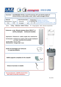
LP 152 I/E
INTRODUZIONE
INTRODUCTION
Negli impianti di riduzione e misura del gas naturale è
buona norma proteggere i regolatori di pressione, le
valvole, i contatori volumetrici ecc. , dalle particelle solide
eventualmente contenute nel gas.
I filtri hanno il compito di assolvere a questa funzione.
Vengono costruiti in varie configurazioni e grandezze al
fine di soddisfare tutte le esigenze di impianto. Sono
provvisti di raccordi filettati per il montaggio di vari
accessori che si rendessero utili per il buon utilizzo.
Di solida costruzione presentano una grande facilità di
montaggio e di manutenzione. L’elemento filtrante è in
grado di filtrare le particelle solide con filtrazioni fino a 5 µ.
In the gas pressure reduction and metering plants, it is
good practice to protect the pressure regulators, the
valves, the positive displacement meters etc. from the
solid particles present in the gas, if any.
The filters are used to this purpose.
They are manufactured in different types and sizes in
order to meet all the plants needs. They are equipped with
nipples for the assembly of the several accessories useful
for a good operation.
The filters construction is stout and they may be easily
installed and maintained. The filtering element is able to
filter the solid particles with filtrations up to 5 µ.
CALCOLO DELLA SUPERFICIE FILTRANTE
CALCULATION OF FILTERING AREA
Q
A=
P x V x 3600
Dove:
A= Area della superficie filtrante in mq.
Q= Portata del filtro in Stm3/h.
P= Pressione assoluta in bar.
V= Velocità alla cartuccia filtro in m/sec. (consigliata 0,33).
Where:
A= Filtering area in smq.
Q= Filter flow rate Stm3/h.
P= Absolute pressure in bar.
V = Speed at the filter cartridge in m/sec (suggested 0,33).
DIMENSIONI CARTUCCE FILTRANTI
FILTERING CARTRIDGE DIMENSIONS
TIPO
TYPE
GC 01 GC 02 GC 10 GC 20 G 0,5
G1
G 1,5
G2
G 2,5
G3
G4
G5
G6
H (mm)
50
65
100
130
120
165
210
270
283
320
415
470
625
Ø A (mm)
70
90
70
90
80
95
120
165
200
252
299
390
475
Ø B (mm)
30
40
30
40
35
50
69
86
110
138
186
246
320
0,12
0,12
0,22
0,06
0,125
0,23
0,47
0,725
0,95
1,45
2,30
4,20
Superficie
filtrante (mq)
0,066
Filter. area
(sqm)
2
FILTRI A CARTUCCIA AF - AF CARTRIDGE FILTERS
Fig. 1
Fig. 2
CARATTERISTICHE PRINCIPALI
-
Pressione massima di esercizio: 10 bar
Temperatura di esercizio: -10 +60°C
Impiego: gas naturale, gas manifatturato, gas non aggressivi
Modelli disponibili: AF1, AF2, AF10, AF20
Connessioni: Rp secondo ISO 7/1 - fig. 1 (a richiesta connessioni a flange scorrevoli PN 16 - fig. 2)
Maximum service pressur: 10 bar
Working temperature: -10 bar +60°C
Use: natural gas, town gas, non corrosive gases
Available sizes: AF1, AF2, AF10, AF20
Connections: Rp according to ISO 7/1 - fig. 1 (sliding flanges
PN 16 upon request - fig. 2)
MATERIALS
MATERIALI
- Body head: aluminium GAI Si9 Mn Mg UNI 3051
- Stud bolt: carbon steel class 8.8
- Sealing gasket: nitrile rubber
- Corpi/Testata: alluminio GAI Si 9 Mn Mg UNI 3051
- Tirante di chiusura: acciaio al carbonio classe 8.8
- Guarnizione di tenuta: gomma nitrilica
FILTERING ELEMENT
ELEMENTO FILTRANTE
- Tipo: cartuccia plissettata in fibra di cellulosa trattata con
resina fenolica, imputrescibile ed idrorepellente
- Grado di filtrazione: 20µm
- Efficienza: 98%
- Guarnizioni: feltro pressato
- Superficie filtrante:
660 cm2 per filtro AF1 (cartuccia GC01)
1200 cm2 per filtro AF2 (cartuccia GC02)
1200 cm2 per filtro AF10 (cartuccia GC10)
2200 cm2 per filtro AF20 (cartuccia GC20)
- Type: plated cartridge made of cellulose fibre, treated with
phenolic resin, imputrescible and water-repellent
- Filtering capacity: 20 µm
- Efficiency: 98%
- Gaskets: pressed felt
- Filtering area:
660 cm2 for filter AF1 (cartridge GC1)
1200 cm2 for filter AF2 (cartridge GC2)
1200 cm2 for filter AF10 (two cartridges GC10)
2200 cm2 for filter AF20 (two cartridges GC20)
INGOMBRI - DIMENSIONI - PESI • OVERALL DIMENSIONS - WEIGHTS
B
B
D
D
H
DNu
H
L
L
A
A
DNe
I
AF...
Modello
Size
Dne*/Dnu*
A
B
D
H
I
L
M
AF... L
AF1
AF2
1”
60
60
115
115
145
115
1”1/2
70
70
140
140
185
125
DNu
M
DNu
-
MAIN FEATURES
AF10
AF20
AF1 L
AF2 L
1”
60
60
115
170
200
115
1”1/2
70
70
140
200
245
125
1”
126
145
160
185
-
1”1/2
126
145
160
185
-
3
FILTRI A CARTUCCIA - CARTRIDGE FILTERS
HFA/... - HFB/...
HFB/...
HFA/...
CARATTERISTICHE PRINCIPALI
MAIN FEATURES
-
Max working pressure: up to 17,6 bar
Max working temperature: up to 60 °C
Service: natural gas, town gas, non corrosive gases.
Colletting capacity: over 12% of total filter capacity with
drain on botton part
- Flanging: ANSI 150 RF and PN 16 UNI/DIN
- Connections: in-line HFA/... or right angles HFB/...
- Pressione massima di esercizio: fino a 17,6 bar
- Temperatura massima di esercizio: fino a 60 °C
- Impiego: gas naturale, gas manifatturato, gas non
aggressivi
- Capacità di raccolta: superiore al 12% della capacità
totale del filtro con spurgo sulla parte inferiore
- Flangiatura: ANSI 150 RF e PN 16 UNI/DIN
- Connessioni: in linea HFA/... o a squadra HFB/...
MATERIALS
MATERIALI
- Pipe: ASTM A 106 Gr. B
- Flanged: ASTM A 105
- Tubo: ASTM A 106 Gr. B
- Flange: ASTM A 105
FILTERING ELEMENT
ELEMENTO FILTRANTE
-
- Material: Felt polyester drilled and reinforcing steel
plate.
- Filtering capacity: 3 - 5 - 50 µm
- Efficiency: 98%
- Type: 0,5 - 1 - 1,5 - 2 - 2,5 - 3 - 4 - 5 - 6
Materiale: Poliestere di feltro e lamiera di rinforzo forata
Grado di filtrazione: 3 - 5 - 50 µm
Efficienza: 98%
Tipo: 0,5 - 1 - 1,5 - 2 - 2,5 - 3 - 4 - 5 - 6
AVAILABLE ACCESSORIES
ACCESSORI A RICHIESTA
- Singola o doppia valvola di spurgo
- Indicatore di intasamento
- Indicatore di intasamento con allarme a distanza (contatto tipo reed)
- Manifold 3 valvole 5 vie in acciaio al carbonio o inossidabile per by-pass dell’indicatore di intasamento
- Manometro
- Pressostato differenziale
- Livellostato
tipo
type
HFA/0,5 HFB/0,5
HFA/1
HFB/1
HFA/1,5 HFB/1,5
HFA/2
HFB/2
HFA/2,5 HFB/2,5
HFA/3
HFB/3
HFA/4
HFB/4
HFA/5
HFB/5
HFA/6
-
DN bocchelli disponibili
available nozzle DN
25
-
32
-
40
40
65
80
100
125
150
200
300
50
50
80
100
125
150
200
250
350
DN spurgo
drain DN
1
/2”
/2”
1
/2”
1
/2”
1
/2”
1”
1”
1”
1”
1
-
Single or double drain ball valve
Clogging indicator
Loss of pressure indicator with remote switch (reed contact)
3 valves 5 ways carbon or stainless steel manifold for
loss of pressure indicator by-pass
- Pressure gauge
- Differential pressure switch
- Level gauge switch
tipo cartuccia
cartridge type
N° cartucce
cartridge Q.TY
peso (kg)
weight (kg)
G0,5
G1
G1,5
G2
G2,5
G3
G4
G5
G6
1
1
1
1
1
1
1
1
1
30
30
42
60
85
115
250
350
800
4
capacità totale (lt)
total volume (liters)
3
5
10
20
40
60
180
215
420
capacità di raccolta (lt)
collecting vol. (liters)
1
1,2
2
5
8
14
27
50
85
DIMENSIONI in mm. / DIMENSIONS in mm.
H
B1
G
D
E
C
G
F
A
B
E
F
DN spurgo
drain DN
D
DN spurgo
drain DN
C1
A
HFA/...
Tipo - type
A
B
B1
C
C1
D
E
F
G
H
0,5
1
1,5
2
2,5
3
4
300
368
350
156
138
212
90
114,3
220
120
400
443
426
178
161
265
120
141,3
250
165
450
528
512
207
191
321
148
168,3
285
210
500
642
624
233
215
409
234
219,1
340
270
600
744
726
271
253
473
237
273
405
283
650
852
835
310
293
542
298
323,8
460
320
800
1032
1010
360
338
672
405
406,4
580
415
5
6
900
1192
1172
444
424
748
450
508
715
470
1100
1490
1787
487
470
1003
912
609
812
625
A
F
B
D
E
C
DN spurgo
drain DN
B
HFB/...
Tipo - type
0,5
1
1,5
2
A
360
425
512
825
B
150
200
230
250
C
115
120
148
D
114,3
141,3
E
220
F
138
3
4
5
726
837
1078
1250
300
350
400
450
234
239
300
405
450
168,3
219,1
273
323,8
406,4
508
250
285
340
405
460
580
715
159
190
215
254
293
336
425
5
2,5
FILTRI A CARTUCCIA - CARTRIDGE FILTERS
HFA/... - TRC/...
HFA/…TRC
HFA/…TRC
CARATTERISTICHE PRINCIPALI
MAIN FEATURES
-
Max design pressure: up to 102 bar
Max working temperature: up to 100 °C
Service: natural gas, town gas, non corrosive gases.
Quick opening clousure
Colletting capacity: over 12% of total filter capacity with drain
on botton part
- Flanging: ANSI 300/600 RF o RJ
- Connections: in-line.
-
Pressione massima di progetto: fino a 102 bar
Temperatura massima di esercizio: fino a 100 °C
Impiego: gas naturale, gas manifatturato, gas non aggressivi
Testata a chiusura rapida
Capacità di raccolta: superiore al 12% della capacità totale del
filtro con spurgo sulla parte inferiore
- Flangiatura: ANSI 300/600 RF o RJ
- Connessioni: in linea.
MATERIALI
MATERIALS
- Tubo: ASTM A 106 Gr. B
- Flange: ASTM A 105
- Pipe: ASTM A 106 Gr. B
- Flanged: ASTM A 105
ELEMENTO FILTRANTE
-
FILTERING ELEMENT
Materiale: Poliestere di feltro e lamiera di rinforzo forata
Grado di filtrazione: 3 - 5 - 50 µm
Efficienza: 98%
Tipo: 1 - 1,5 - 2 - 10 - 15 - 20 - 25 - 30 - 40 - 50 - 60
-
ACCESSORI A RICHIESTA
AVAILABLE ACCESSORIES
-
Singola o doppia valvola di spurgo
Indicatore di intasamento
Indicatore di intasamento con allarme a distanza (contatto tipo reed)
Manifold 3 valvole 5 vie in acciaio al carbonio o inossidabile
per by-pass dell’indicatore di intasamento
- Manometro
- Pressostato differenziale
- Livellostato
tipo
type
HFA/1
HFA/1,5
HFA/2
HFA/10
HFA/15
HFA/20
HFA/25
HFA/30
HFA/40
HFA/50
HFA/60
DN bocchelli disponibili
available nozzle DN
TRC
TRC
TRC
TRC
TRC
TRC
TRC
TRC
TRC
TRC
TRC
1”
2”
3”
8”
1 1/2”
2”
2”
2 1/2”
4”
6”
10”
2”
2 1/2”
3”
2 1/2”
3”
3”
5”
5”
6”
8”
12”
Material: felt polyester and drilled reinforcing steel plate.
Filtering capacity: 3 - 5 - 50 µm
Efficiency: 98%
Type: 1 - 1,5 - 2 - 10 - 15 - 20 - 25 - 30 - 40 - 50 - 60
2 1/2”
3”
4”
3”
4”
4”
6”
6”
8”
10”
14”
-
Single or double drain ball valve
Clogging indicator
Loss of pressure indicator with remote switch (reed contact)
3 valves 5 ways carbon or stainless steel manifold for loss of
pressure indicator by-pass
- Pressure gauge
- Differential pressure switch
- Level gauge switch
DN spurgo tipo cartuccia N° cartucce
peso (kg)
capacità totale (lt) capac. di raccolta (lt)
drain DN cartridge type cartridge Q.TY weight (kg) total volume (liters) collecting vol. (liters)
1
/2”
/2”
1
/2”
1
/2”
1
/2”
1”
1”
1”
1”
1 1/2”
1 1/2”
1
G1
G1,5
G2
G1
G1,5
G2
G2,5
G3
G4
G5
G6
1
1
1
2
2
2
2
2
2
2
2
6
55
60
110
65
75
170
320
370
690
1400
2000
6
10
21
10
15
30
50
85
170
320
550
1,2
2
5
8
14
27
50
85
85
85
85
DIMENSIONI in mm. / DIMENSIONS in mm.
Cartuccia
Cartridge
Disco di chiusura
Targa
caratteristiche
Name plate
Closure disk
RP 1/2” UNI-ISO 7/1
con tappo
With Plug
Targa
caratteristiche
Name plate
dn spurgo
Drain dn
Cartuccia
Cartridge
dn spurgo
Drain dn
HFA/30 - TRC ÷ HFA/60 - TRC
HFA/1 - TRC ÷ HFA/15 - TRC
Tipo - type
1
1,5
2
10
15
20
25
30
40
50
60
A
530
613
756
706
860
1560
1600
2031
2435
2694
3209
B
343
404
488
519
630
1230
1235
1611
1885
2034
2459
C
187
209
268
187
230
-
-
-
-
-
-
D
141,3
168,3
219,1
141,3
168,3
219,1
273
323,8
406,4
508
609,6
E
500
550
650
500
550
650
750
800
1000
1100
1200
F
-
-
-
-
-
200
200
250
320
350
400
G
-
-
-
-
-
330
365
420
550
660
750
H
-
-
-
-
-
800
800
800
900
1000
1100
L
-
-
-
-
-
350
425
475
520
640
700
M
165
210
270
165
210
270
283
320
415
470
625
7
LP 152 I/E
I dati sono indicativi e non impegnativi. Ci riserviamo di apportare eventuali modifiche senza preavviso.
The data are not binding. We reserve the right to change them without prior notice.
Pietro Fiorentini S.p.A.
UFFICI COMMERCIALI: - OFFICES:
I-20124 MILANO
Italy - Via Rosellini, 1 - Phone +39.02.6961421 (10 linee a.r.) - Fax +39.02.6880457 • E-mail: [email protected]
I-36057 ARCUGNANO (VI)
Italy - Via E. Fermi, 8/10 - Phone +39.0444.968511 (10 linee a.r.) - Fax +39.0444.960468 • E-mail: [email protected]
ASSISTENZA POST-VENDITA E SERVIZIO RICAMBI: - SPARE PARTS AND AFTER-SALES SERVICE:
I-36057 ARCUGNANO (VI)
Italy - Via E. Fermi, 8/10 - Phone +39.0444.968511 (10 linee a.r.) - Fax +39.0444.968513 • E-mail:[email protected]
mod dic.2014
Scaricare