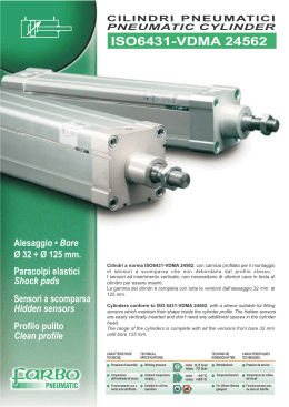
CILINDRI A NORME ISO 15552
Ø32 ÷ Ø320 mm, FISSAGGI ED ACCESSORI.
CYLINDER STANDARD ISO 15552
Ø32 ÷ Ø320 mm, FIXING AND ACCESSORIES.
Cat. n° B 0 1 0 8
2
INDICE - INDEX
CARATTERISTICHE TECNICHE
OPERATING FEATURES
Pagina
Page
4
INFORMAZIONI TECNICHE
TECHNICAL INFORMATION
Pagina
Page
6
Lunghezza di ammortizzo
Energia ammortizzabile
Masse dei cilindri
Consumo d’aria
Effective cushioning length
Max cushioning kinetic energy
Inertial mass of cylinders
Air consumption
FORZE TEORICHE
THEORETICAL THRUSTS
Pagina
Page
7
DIMENSIONI DI INGOMBRO
OVERALL DIMENSIONS
Pagina
Page
8
Tolleranze nominali sulla corsa
Materiali e dotazioni standard
Nominal tollerance of stroke
Material and standard accessories
CODICI DI ORDINAZIONE CILINDRI
CYLINDER ORDER CODES
Pagina
Page
9
Come ordinare
Esecuzioni speciali
Code example
Special versions
FISSAGGI CILINDRI
CYLINDER FIXING
Pagina
Page
13
Codici di ordinazione
Punto di riferimento delle quote di ingombro
Masse
Fixing order codes
Reference of overall dimensions
Mass of cylinder fixing
FISSAGGI ALLO STELO
ROD FIXING
Pagina
Page
17
Codici di ordinazione
Masse
Rod fixing order codes
Mass of rod fixing
SENSORI MAGNETICI
MAGNETIC SWITCHES
Pagina
Page
18
Fissaggi sensori magnetici
Codici di ordinazione
Dimensioni di ingombro
Brackets for magnetic switches
Magnetic switches order codes
Magnetic switches overall dimensions
Le informazioni tecniche di questo catalogo sono soggette a variazioni senza preavviso.
The technical information presented in this catalogue could be subject to variations without notice.
3
CILINDRI A NORME ISO 15552 - CYLINDER STANDARD ISO 15552
CARATTERISTICHE TECNICHE E STANDARD QUALITATIVI
Con questo catalogo AIRON presenta i cilindri conformi alle norme ISO 15552 dall'alesaggio 32 mm al 320 mm.
Sostanzialmente sono disponibili due serie di cilindri: la "B...." dall'alesaggio 32 al 320 mm.; la "H...." dall'alesaggio 32 al 100 mm.
Le caratteristiche tecniche comuni sono la robustezza, l'affidabilità e la particolare predisposizione per essere personalizzati.
La particolare attenzione di AIRON nell'ottimizzazione dei materiali e dei processi produttivi della serie "H", ultima nata, permette
di offrire un prodotto con un rapporto prezzo/prestazioni molto interessante.
Inoltre per soddisfare al meglio le richieste della clientela AIRON offre per entrambe le serie la possibilità di allestire il cilindro con
camicie di diverso profilo: a sezione quadra (.F...) per alloggiare i sensori del tipo a "scomparsa", con profilo a lobi (.P...) per una
esecuzione "pulita" e a sezione tonda (.T...) per una esecuzione classica, permettendo così al cliente di abbinare il tipo di sensore
che preferisce (vedi pag. 18).
Dalle sezioni di seguito riportate sono visibili tutti i componenti del cilindro:
• Le testate (1) in alluminio fuso con trattamento di ossidazione anodica per la serie "B", di verniciatura per la "H".
• La camicia (2) sulla quale vengono eseguite le filettature per il fissaggio alle testate con un procedimento di
"rullatura" per conferire maggior resistenza meccanica all'accoppiamento filettato.
• Il gruppo pistone-coni di ammortizzo (3-4) in lega di alluminio lavorata su macchine utensili per un
ottimale accoppiamento pistone-camicia. Il pistone oltre ad alloggiare l'anello magnetizzato (5) che
permette l'impiego di sensori magnetici, è di supporto al nastro in PTFE caricato grafite (6) che
unitamente alla boccola (7) montata sulla testa anteriore conferisce una maggior guida al gruppo
stelo-pistone permettendo alle guarnizioni (8-9) di lavorare correttamente anche nelle
condizioni più gravose, aumentando così la vita stessa del cilindro.
• Gli smorzatori meccanici d'urto in materiale elastico (10) presenti nella serie "H",
riducono al minimo i rumori derivanti dall'impatto pistone-testate, a favore
della qualità dell'ambiente di lavoro.
6
Nella fase di montaggio, le parti in scorrimento vengono
ingrassate con un grasso dalle elevate caratteristiche di
lubrificazione ed adesione superficiale, permettendo
così al cilindro di lavorare anche con aria non
lubrificata; successivamente viene sottoposto ad
un controllo funzionale per garantire la
massima affidabilità.
3
4
9
BF ....
4
7
5
2
8
1
HF ....
OPERATING FEATURES AND QUALITY STANDARDS
With this catalogue AIRON wants to introduce the ISO 15552 cylinders from 32 to 320 mm bore.
Basically are available two series: “B...” series from 32 to 320 mm bore and “H...” series from 32 to 100 mm bore.
Common technical features are the robustness, realibility and the possibility to be customized.
Special attention has been reserved to the “H....” series during the designing about materials and manufacturing technology to
make a product with a very interesting price-quality relation.
Moreover, in order to satisfy the customer's request, AIRON offers, for both series, to get the cylinders with different tubes;
square shape (.F...) suitable to use with the sensors in the slot, mickey mouse shape (.P...) and round tube with tie rods for classic
version (.T...). These tubes allow to the customer to choose any kind of sensors. (see page 18).
In the section drawing below are visible all the components of the cylinder:
• End caps (1) made of die casting aluminium with anodizing treatment for the “B” series and painting for the “H” series.
• Tube (2) is threaded using a rolling techology to give a better mechanical resistance to the coupling with the end cap.
• The piston and cones assembly (3-4) has made using CNC machines
to optimize the accuracy of the mechanism.
Moreover piston has a magnet inside (5)
for the sensors and has a
guiding strip made of
PTFE filled of Carbon
(6) that together with
bushing (7) on the front
end cap gives a better
guide to the cylinder.
The piston guide helps the
seals (8-9) to work well even in
the hardest conditions.
• Mechanical dampers (10) are standard
equipment in the "H" series in order to reduce
noise and energy absorption.
1
10
2
10
2
During the assembling, sliding coupling are lubricated using a
special grease that allows the cylinder to work
even with dryed hair.
HF ....
BF ....
Camicia profilata per sensori a scomparsa
Profiled cylinder barrel for a foldaway magnetic switches
2
HP ....
BP ....
Camicia profilata a lobi
Profiled cylinder barrel
2
HT ....
BT ....
Camicia tonda
Round barrel
5
Informazioni tecniche - Technical information
Fluido - Fluid:
aria filtrata 40 μm lubrificata o non lubrificata (se lubrificata usare olio per circuiti pneumatici).
filtered air 40 μm lubricated or not lubricated ( when lubricated use oil for pneumatic circuits).
Temperatura fluido ed ambiente - Fluid and room temperature: -10/+80 °C
(consultare la tabella varianti dei cilindri e temperature di utilizzo dei finecorsa).
(consult the variants tables of cylinders and the referring temperatures of magnetic switch).
Pressione di esercizio - Working pressure: 1 ÷ 10 bar
Velocità massima - Maximum speed: 1 m/s
Lunghezza di ammortizzo - Effective cushioning length
Alesaggio - Bore (mm)
32
40
50
63
80
100
125
160
200
250
320
Lunghezza - Length (mm)
20
21
22
23
27
27
37
37
40
45
48
Corsa espressa in mm nella quale agisce effettivamente l’ammortizzo pneumatico.
Limit stroke expressed in mm during which the pneumatic cushioning really works.
Energia ammortizzabile - Max cushioning kinetic energy
Alesaggio - Bore (mm)
32
40
50
63
80
100
125
160
200
250
320
Energia - Energy ( J )
1,9
2,2
4
6
11
16
37
43
84
120
170
Energia massima assorbibile dall’ammortizzo pneumatico (considerare la massima velocità di 1 m/s).
Max absorbing energy of pneumatic cushioning (consider the max speed of 1 m/s).
Masse dei cilindri - Inertial mass of cylinders
Alesaggio - Bore (mm)
32
40
50
63
80
100
125
160
200
250
320
Mb - Mb ( g )
540
690
1050
1500
2400
3600
6350
13000
14500
33380
42090
Mu - Mu ( g )
2,3
3,2
4,8
5,1
7,6
8,8
13
21
25
36
60
Per il calcolo della massa dei cilindri ISO 6432 si utilizza la seguente formula:
To evaluate the inertial mass of cylinders ISO 6432 please use the following formula:
Mt
= Massa totale (g) - total mass
Mb
= Massa cilindro corsa 0 (g) - Cylinder mass stroke 0
Mu
= Massa per millimetro di corsa (g / mm) -Mass per millimeter of stroke
C
= Corsa del cilindro (mm) - Stroke of cylinder
Mt = Mb + (Mu•C)
NB:
non
NB:
and
Le differenze tra le masse dei cilindri della serie BF, BP e BT sono trascurabili, lo stesso vale per le versioni magnetiche e
magnetiche.
The differences between the masses of the BF, BP and BT series are negligible, the same is between the magnetic
non-magnetic versions.
Consumo d'aria - Air consumption
La determinazione del consumo di aria libera del cilindro espresso in Nl / min risulta di notevole importanza per la scelta del
compressore e può essere calcolato utilizzando la seguente formula:
It is very important to determine the free air consumption, expressed in NI / min, inside the cylinder for the choice of compressor and this can
be evaluated by using the following formula:
Q =
6
A•2C•n•(p+1)
1000
Q
A
C
n
p
=
=
=
=
=
Consumo di aria (Nl/min) - Air consumption
Area di spinta (cm2: tab. 4) - Thrust surface
Corsa del cilindro (cm) - Cylinder stroke
N° di cicli al minuto (x/min) - N° of cycles per minute
pressione relativa di lavoro (bar) - Working pressure
Forze teoriche - Theorical thrust
La tabella seguente permette di determinare le forze teoriche sviluppate dai cilindri sia in fase di uscita dello stelo che in fase di
rientro. Il valore indicato in grassetto rappresenta la forza in spinta mentre l’altro la forza in rientro; nel caso di cilindro a stelo passante si deve considerare il secondo valore sia in spinta che in tiro.
The following table permits to determine the theoretical thrusts developed by cylinders during both the rod outlet and its inlet. The value in bold
represents the thrust force while the others the tractive force; in the case of through rod cylinder the second value, both the thrust and the
tractive one, is to be considered.
Stelo passante - Through rod (SP)
Stelo semplice - Single rod
Tabella delle forze teoriche - Theorical thrust
Alesaggio - Bore (mm)
32
40
50
63
80
100
125
160
200
250
320
Superficie in spinta (cm2)
Surface to thrust
8,04
12,56
19,63
31,16
50,24
78,50
122,66
200,96
314,00
490,6
804
Superficie in trazione (cm2)
Surface to draught
6,91
10,55
16,50
28,00
45,36
71,43
115,99
188,40
301,44
471
773
Pressione - Pressure (Bar)
Forza - Thrust (N)
1
spinta - thrust
trazione - draught
80
69
125
105
196
165
311
280
502
453
785
714
1226
1160
2009
1884
3140
3014
4906
4710
8040
7730
2
spinta - thrust
trazione - draught
160
140
251
211
393
330
623
560
1005
907
1570
1429
2453
2319
4019
3768
6280
6028
9812
9420
16080
15460
3
spinta - thrust
trazione - draught
240
207
376
316
588
494
934
840
1507
1360
2355
2143
3679
3479
6028
5652
9420
9043
14718
14130
24120
23190
4
spinta - thrust
trazione - draught
322
276
502
422
785
660
1246
1120
2010
1814
3140
2857
4906
4639
8038
7536
12560
12057
19624
18840
32160
30920
5
spinta - thrust
trazione - draught
402
345
628
528
981
824
1558
1401
2512
2266
3925
3571
6133
5799
10048
9420
15700
15072
24530
23550
40200
38650
6
spinta - thrust
trazione - draught
482
414
754
633
1178
990
1869
1680
3014
2722
4710
4286
7359
6959
12057
11304
18840
18086
29436
28260
48240
46380
7
spinta - thrust
trazione - draught
563
484
879
739
1373
1154
2181
1961
3516
3173
5495
5000
8586
8119
14067
13188
21980
21100
34342
32970
56280
54110
8
spinta - thrust
trazione - draught
643
553
1005
844
1570
1320
2493
2240
4019
3629
6280
5715
9812
9279
16076
15072
25120
24115
39248
37680
64320
61840
9
spinta - thrust
trazione - draught
724
622
1130
950
1765
1484
2804
2521
4521
4079
7065
6428
11039
10439
18086
16956
28260
27129
44154
42390
72360
69570
10
spinta - thrust
trazione - draught
804
691
1256
1055
1963
1650
3116
2800
5024
4536
7850
7143
12266
11599
20096
18840
31400
30144
49060
47100
80400
77300
In generale la scelta del diametro ottimale del cilindro coinvolge un numero elevato di fattori i quali rendono laboriosa la soluzione.
L’esperienza pratica consiglia di dimensionare il cilindro in modo tale che la sua spinta (alla pressione di lavoro prescelta) sia compresa
Tra 1,5 e 2 volte il valore del carico da movimentare.
In general, to choose the optimum diameter of cylinder, a lot of different factors are to be considered, which could make the solution
difficult. According to our experience, we suggest to size up the cylinder till its thrust (to the chosen work pressure) is between 1.5 and 2 times
the value of load to move.
7
DIMENSIONI DI INGOMBRO - OVERALL DIMENSIONS
EE
VD
G
M
M
E
R
VA
AM
WH
R
E
KK
N
N
SW
BG
G
F
D
L + corsa - stroke
Stelo semplice
Single rod
Il cilindro é fornito completo di dado stelo - The cylinder is provided complete with the rod nut
EE
VD
G
E
R
M
M
AM
WH
R
E
KK
N
N
SW
F
D
BG
G
F + corsa - stroke
L + corsa - stroke
Stelo semplice
Single rod
Il cilindro é fornito completo di dado stelo - The cylinder is provided complete with the rod nut
Serie - Serie
Alesaggio - Bore (mm)
32
40
50
63
80
100
125
160
200
250
320
A
B
12 30
16 35
20 40
20 45
25 45
25 55
32 60
40 65
40 75
50 90
63 110
H..
B..
D
E
M6 45,5 47
M6 52
53
M8 65
65
M8 75
75
M10 95
95
M10 114 115
M12
140
M16
180
M16
220
M20
275
M24
345
H..
B..
F
G
48 26
28
54 26 31,5
69 29,5 31,5
69 29,5 35
86 35
36
91 35
41
119
45
152
49
167
49
189
57
216
57
H..
L
M
94
13
105 14
106 15,5
121 16,5
128 19
138 19
160
180
180
200
220
-
B..
H..
B..
N
14
16
21
22
23
26
30
29
29
31
31
4
4
5
9
11
16,5
-
4,5
5,5
8,5
8,5
8,5
10
12,5
1
0
0
0
H..
R
32,5
38
46,5
56,5
72
89
110
140
175
220
270
AM
22
24
32
32
40
40
54
72
72
84
96
BG
16
16
16
16
16
16
20
24
24
25
28
EE
G1/8
G1/4
G1/4
G3/8
G3/8
G1/2
G1/2
G3/4
G3/4
G1
G1
KK
M10x1,25
M12x1,25
M16x1,5
M16x1,5
M20x1,5
M20x1,5
M27x2*
M36x2
M36x2
M42x2
M48x2
SW
10
13
17
17
21
21
27
36
36
46
55
160
200
VA
4
4
4
4
4
4
5
5
5
10
10
B..
VD
15
17
24
24
30
32
-
20
22
28
28
34
38
50
50
60
75
90
WH
26
30
37
37
46
51
65
80
95
105
120
* A richiesta M24x2 - * On request M24x2
Tolleranze nominali sulla corsa - nominal tollerances of stroke
Alesaggio - Bore
Fino a 500 mm - Up to 500 mm
32
(mm)
Da 501 a 1250 mm - From 501 to 1250 mm (mm)
40
50
+2
0
+3,2
0
63
80
+2,5
0
+4
0
100
125
250
320
+4
0
+5
0
Materiali standard - Standard material
Testate.................................... H.. : 32 - 100; alluminio pressofuso verniciato
B.. : 32 - 125; alluminio pressofuso anodizzato
: 160 - 320; alluminio fuso in conchiglia
Stelo.............................................. : acciaio C45 cromato
Camicia...................... HF. / BF. : alluminio profilato estruso anodizzato
HP. / BP. : alluminio profilato estruso anodizzato
HT. / BT. : alluminio tondo anodizzato
Tenuta stelo................... H.. / B.. : poliuretano
Tenute pistone e ammortizzo.. H.. : poliuretano
B.. : gomma NBR
Altre tenute.................... H.. / B.. : gomma NBR
Smorzatori d'urto (solo serie H.. ): poliuretano
8
Covers................................. H.. : 32 - 100; painted die cast aluminium
B.. : 32 - 125; anodized die cast aluminium
: 160 - 320; shell mold casting
Piston rod.................................. : C45 cromium plated steel
Barrel...................... HF. / BF. : anodized aluminium profiled barrel
HP. / BP. : anodized aluminium profiled barrel
HT. / BT. : aluminiun tube
Piston rod seal.......... H.. / B.. : polyurethane
Piston seals and cushioning.. H.. : polyurethane
B.. : NBR
Others seals.............. H.. / B.. : NBR
Elastic stopper (only H.. series): polyurethane
CODICI DI ORDINAZIONE DEI CILINDRI - CYLINDERS ORDER CODES
H
B
Serie "H" alesaggio 32 - 100.
"H" serie bore 32 - 100.
Serie "B" alesaggio 32 - 320.
"B" serie bore 32 - 320.
F
P
T
ISO 15552
Camicia in alluminio profilato per sensori a scomparsa alesaggi 32 - 125.
Camicia in alluminio profilato per sensori a scomparsa alesaggi 32 - 125.
Camicia in alluminio profilato a lobi alesaggi 32 - 200.
Camicia in alluminio profilato a lobi alesaggi 32 - 200.
Esecuzione a tiranti alesaggi 32 - 320.
Esecuzione a tiranti alesaggi 32 - 320.
M
S
Magnetico
Magnetic
Corsa
Stroke (mm)
Non magnetico
Non magnetic
Alesaggio
Bore
32; 40; 50; 63; 80;
100; 125; 160; 200;
250; 320 mm.
H F M 0 3 2
Indicare in successione i codici delle
varianti
o
esecuzioni
speciali
eventualmente richieste (vedi pagina 10).
Corse standard:
Standard stroke:
25; 40; 50; 75; 80; 100;
125; 150; 160; 200; 250;
320; 400; 500; 600;
700; 800; 900; 1000 mm.
Please indicate in sequence the codes of
variants or special versions possibly
requested (see page 10).
0 2 5 0 A 4 KK
Codice
Code
Varianti -Variants
Esecuzione:
Version:
Stelo:
Rod:
Solo tenuta stelo:
Only piston rod seal:
Tutte le tenute:
All seals:
**) Ammortizzo pneumatico:
**) Pneumatic cushioning:
SP
A4
AISI 304 cromato
AISI 304 cromato AC
)
Elastomero
fluorurato
*
*) Fluorine rubber VS
EPDM etilene propilene
EPDM ES
)
Elastomero
fluorurato
*
*) Fluorine rubber GV
Solo anteriore
Front only AA
Solo posteriore
Rear only AP
Non presente
Not present NA
Stelo passante
Through rod
AISI 304
AISI 304
H.. - B..
R
R
R
R
R
R
R
R
R
R = a richiesta -on request
*) = Temperatura max 150°C - Max temperature 150°C
**) = Di serie con ammortizzo anteriore e posteriore - Standard front and rear pneumatic cushioning
Come ordinare - Code example
Cilindro ISO con camicia in alluminio profilato per
sensori a scomparsa, pistone magnetico, alesaggio 63 mm,
corsa 250 mm, tenuta stelo in elastomero fluorurato.
ISO cylinder with aluminium profiled barrel for foldaway magnetic
switches, magnetic piston, bore Ø63 mm and stroke 250 mm,
piston rod seal in fluorine rubber.
HFM.063.0250.VS
Codice kit guarnizioni - Seals kit code
Codice kit guarnizioni = SG + tipo cilindro + alesaggio + eventuali varianti.
Seals kit code = SG + cylinder type + bore + possible versions.
SG.HFM.063.SP
9
ESECUZIONI SPECIALI - SPECIAL VERSIONS
CODICE - CODE
AM ..
DESCRIZIONE - DESCRIPTION
COME ORDINARE - HOW TO ORDER
Estremità dello stelo filetto maschio
con lunghezza a richiesta.
Dopo il codice del cilindro inserire la
sigla “AM” seguita dalla lunghezza della
filettatura richiesta.
Screw tap rod end with length on
request.
AM
After the cylinder code insert the initials “AM”
followed by the screw length to request.
Es.: BFM.050.0200.AM60
WH ..
Sporgenza dello stelo a richiesta.
Dopo il codice del cilindro inserire la
sigla “WH” seguita dalla lunghezza della
sporgenza dello stelo richiesta.
Rod protrusion on request.
WH
After the cylinder code insert the initials “WH”
followed by the required rod postrusion.
Es.: BFM.050.0200.WH80
SF
Estremità dello stelo filettata femmina.
Dopo il codice del cilindro inserire la sigla “SF”.
Female screw thread rod end.
After the cylinder code insert the initials “SF”.
K
Es.: BFM.050.0200.SF
Alesaggio - Bore
Z
WH
WH = Standard
Standard
SD
(mm)
Z
K
32
40
M6
12
M8
12
50
63
80
100 125 160 200 250 320
M10 M10 M12 M12 M16 M20 M20 M30 M36
14
14
16
16
32
40
40
50
60
Estremità dello stelo a disegno del
cliente.
Rod end according to the customer’ s
drawing.
Indicare il codice del cilindro, inserire la
sigla “SD” ed allegare all’ordine il disegno
(o lo schizzo) adeguatamente quotato.
Indicate the cylinder code, insert the initials
“SD” and enclose to the order the drawing
(or sketch) properly dimensioned.
Es.: BFM.050.0200.SD
KK
Filettatura metrica passo grosso.
Dopo il codice del cilindro inserire la sigla “KK”.
Metrical thread.
After the cylinder code insert the initials “KK” .
Es.: BFM.050.0200.KK
Alesaggio - Bore
(mm)
KK
KK
32
40
50
63
80
100 125 160 200 250 320
M10 M12 M16 M16 M20 M20 M27 M36 M36 M42 M48
Per filettature diverse da tabella inserire la sigla "KK=..." con il filetto richiesto.
For different rod threads write in the order the following “KK=...” and the requested value.
C ...
J
Es.: BFM.050.0200.KK=M10x1,25
Cilindri contrapposti per realizzare 3
posizioni (con 2 cilindri di uguale
corsa) o 4 posizioni (con 2 cilindri di
corsa diversa.
Dopo il codice del cilindro inserire la sigla “C”
seguito dalla corsa del secondo cilindro.
Cylinders opposed by 3-position (with 2
cylinders having the same stroke) or
4-position covers (with 2 cylinders
having different stroke).
Es.: BTM.050.0100.C0100
After the cylinder code enter the initial “C” followed
by stroke of second cylinder.
(3 posizioni - 3-positions)
Es.: HFM.050.0100.C0150
(4 posizioni - 4-positions)
Con l'accessorio "FUI" l'utilizzatore può gestire il collegamento di 2 cilindri con camicia
profilata (HF..., HP..., BF..., BP...) con una semplice operazione di montaggio.
Using "FUI" coupling accessories, final user can assembly by itself 2 cylinders (HF..., HP..., BF...,
BP...) in a simple way.
Es.: FUI.050
(flangia di unione - Coupling flange)
Z
FUI. ...
Alesaggio - Bore (mm)
32
40
50
63
80
100
125 160 200 250 320
* J (± 0,1 mm)
** Z (± 0,1 mm)
9
11
9
11
10
11,5
10
11,5
10
14
10
14
12
-
Kit assemblaggio
Assembling kit code
FUI.032 FUI.040 FUI.050 FUI.063 FUI.080 FUI.100
* : per camicia tonda - for round barrel.
10
** : per camicia profilata - for profiled cylinder.
12
-
12
-
22
-
25
-
DESCRIZIONE - DESCRIPTION
COME ORDINARE - HOW TO ORDER
Tandem tiro e spinta.
Questo cilindro sviluppa una forza
multipla (n) rispetto allo standard.
Dopo il codice del cilindro con la
corsa desiderata inserire la sigla “TD”.
NB:
solo
versione
a
tiranti,
l’ingombro assiale risulta multiplo (n)
del corrispondente standard.
Thrust and draught tandem.
This cylinder develops a force of
multiple “n” ompared to the standard.
After the first cylinder code with the
chosen stroke, enter the initials “TD”.
NB: Tie rod version only; please note that
axial dimensions are a multiple “n” of the
corresponding standard.
Es.: BTM.050.0200.TD2
CODICE -CODE
TD ...
Disponibile solo serie "B...".
Avalaible "B..." series only.
GT
=L
+
1)
(n-
C
n
y+
WH
.... (n=2)
...
C
2+
n
+C
C
1+
Alesaggio - Bore
(mm)
Y
L
32
40
50
63
80
100 125 160 200 250 320
53,5
94
62
105
63
106
74
121
82
128
82
138
Cilindri a più posizioni.
Questo cilindro ad n stadi realizza
n+1 posizioni.
Multiple position cylinder.
This “n”-stage cylinder has n +1
positions.
40
30
20
97
160
118
180
118
180
128
200
126
220
Dopo il codice del cilindro inserire la
corsa dei singoli stadi.
Es.: BTM.032.020.030.040 MS
0
0
0
Regolazione corsa in uscita.
Permette di registrare in modo
preciso il punto di massima
estensione dello stelo.
Outlet stroke adjustment.
It allows to adjust precisely
point of rod max extension.
the
Regolazione corsa in rientro.
Permette di registrare in modo
preciso il punto di fine corsa
in rientro dello stelo.
Inlet stroke adjustment.
It allows to adjust precisely
point of inlet limit stop of rod.
Corsa di ammortizzo ridotta.
Reduced cushioning stroke.
the
GT
=L
+C
+(n
WH
... MS
After the cylinder code enter the stroke of
the single stages.
(Cilindro Ø32 a 3 stadi con corsa 20-30-40 mm)
(3-stage Ø32 cylinder with 20-30-40 mm stroke)
20
30
40
y
-1)
Dopo il codice del cilindro inserire la
sigla “RCU” seguita dalla lunghezza di
regolazione.
C1 2
C ..
.
C
WH = Standard - Standard
C = Corsa - Stroke
C1, C2, C... = Corsa singoli stadi
Stroke of single stage.
n = n° stadi - n° stages
Disponibile solo serie "B...".
Avalaible "B..." series only.
RCU ..
Disponibile solo serie "B...".
Avalaible "B..." series only.
RCR ..
After the cylinder code insert the initials
“RCU” followed by the regulation length.
Es.: BFM.050.0200.RCU50
Dopo il codice del cilindro inserire la
sigla “RCR” seguita dalla lunghezza di
regolazione.
After the cylinder code insert the initials
“RCR” followed by the regulation length.
Es.: BFM.050.0200.RCR50
A..
Indicare il codice del cilindro e di
seguito la sigla “AA=...” e "AP=..." con
le lunghezze di ammortizzo richieste.
Write the cylinder's code followed by
“AA=...” and “AP=..” and the requested
value.
=
A=
AP
A
Es.: BFM.050.0200.AA=15.AP=20
(Cilindro Ø50 con ammortizzo anteriore 15 mm e posteriore di 20 mm)
(50 mm bore cylinder with 15 mm lengh of front cushioning and 20 mm lengh of cushioning)
11
CODICE - CODE
SEA
DESCRIZIONE - DESCRIPTION
Disponibile solo serie "B...".
Avalaible "B..." series only.
Cilindro a semplice effetto con molla
anteriore, a riposo stelo rientrato.
Alesaggi 32 ÷ 100, corsa max 50 mm.
Single acting cylinder front spring, inlet
rod at rest.
Bore 32 ÷ 100, max stroke 50 mm.
COME ORDINARE - HOW TO ORDER
Indicare il codice del cilindro e di seguito la
sigla “SEA”. Eventualmente indicare le
forze a stelo rientrato e fuoriuscito.
NB: solo versione non ammortizzata.
Indicate the cylinder code followed by the
initials “SEA”. Indicate the inlet and autlet rod
thrust, if necessary.
N.B.: Not cushioned version only.
Es.: BFM.050.0050.SEA
SEP
Disponibile solo serie "B...".
Avalaible "B..." series only.
Cilindro a semplice effetto con molla
posteriore, a riposo stelo fuoriuscito.
Alesaggi 32 ÷ 100, corsa max 50 mm.
Single acting cylinder rear spring, outlet
rod at rest.
Bore 32 ÷ 100, max stroke 50 mm.
Indicare il codice del cilindro e di seguito la
sigla “SEP”. Eventualmente indicare le forze
a stelo rientrato e fuoriuscito.
NB: solo versione non ammortizzata.
Indicate the cylinder code followed by the
initials “SEP”. Indicate the inlet and autlet rod
thrust, if necessary.
NB: Not cushioned version only.
Es.: BFM.050.0050.SEP
POT
Cilindro con trasduttore di posizione
potenziometrico avente ingombri
conforme cilindri ISO 15552 ad
eccezione della sporgenza del
connettore elettrico.
Cylinder with linear position transducer.
Standard ISO 15552, except for a
electrical connector.
70
Dopo il codice del cilindro inserire la sigla
“POT” oppure “POT90°.PME”.
Per informazioni contattare l’ufficio tecnico.
Insert the initials “POT” or POT90°.PME”
after The cylinder code.
For further
information please contact our technical
department.
Es.: BFM.050.0200.POT90°.PME
Caratteristiche meccaniche e geometriche - Mechanical and dimensional features
Pressione di esercizio fluido - Working pressure:
1 ÷ 10 bar
38
Fluido: aria filtrata 40 μm lubrificata o non lubrificata
Fluid: filtered air 40 μm lubricated or not lubricated
POT90°.PME
1 (-)
2
(SIGNAL)
3 (+)
SCHEMA ELETTRICO
WIRING DIAGRAM
Temperatura fluido ed ambiente - Fluid and room temperature:
-10 ÷ +80 °C
Velocita massima - Maximum speed:
1 m/s
Corse disponibili - Available stroke:
50 ÷ 1000 mm
Alesaggi disponibili - Available bore:
40 ÷ 320 mm
Caratteristiche elettriche per trasduttore PME - Electrical features for PME transducer
Resistenza nel circuito di cursore:
Resistance on slider circuit:
5 KΩ ± 20% corsa - stroke ≤ 300 mm
10 KΩ ± 20% 300 < corsa - stroke ≤ 600 mm
20 KΩ ± 20% corsa - stroke > 600 mm
Linearità indipendente - Independent linearity:
± 0,1% corsa - stroke ≤ 100 mm
± 0,05% corsa - stroke ≤ 100 mm
Risoluzione - Resolution:
∞
Tensione massima applicabile - Max voltage:
40 V corsa - stroke ≤ 50 mm
60 V corsa - stroke ≤ 50 mm
Corrente raccomandata nel circuito cursore:
Max suggested current on the slider circuit:
< 0,1 mA
Vita del trasduttore - Transducer life:
25.000 km
Accessori - Accessories
Condizionatore di segnale in tensione - Signal on voltage conditioner:
(1 - 10 V)
Condizionatore di segnale in corrente - Signal on current conditioner:
(4 - 20 mA)
Convertitore di segnale Analogico/Digitale - Analogic/Digital signal converter
12
COPERTURE DI PROTEZIONE DEL CAVO SENSORI - MAGNETIC SWITCH CABLE COVER
Le coperture di protezione del cavo del sensore magnetico
sono inseribili con un semplice montaggio ad incastro.
FCC
The cable protection cover of magnetic switch is inserible with
a simple grooving mounting.
*
*
Alesaggio
Bore (mm)
Lunghezza camicia corsa 0 ( )
Length of stroke 0 cylinder ( )
32
40
50
63
80
100
125
39
43
44
52
57
57
70
Materiale
Material: .... PVC
Le protezioni del cavo sono fornite in spezzoni di 500 mm di lunghezza.
The cable protection is supplied on segment of 500 mm length.
FISSAGGI CILINDRI - CYLINDER FIXING
I fissaggi proposti permettono un rapido collegamento del cilindro alla macchina. Oltre a quelli previsti dalla normativa ISO 15552
sono disponibili altri modelli che aumentano le possibilità di applicazione del cilindro stesso.
Gli accessori vengono corredati di viti per il fissaggio al cilindro.
The fixing enables a quick connection of the cylinder to the machine. Besides the fixing provided for by the ISO 15552
standards, other models are available to increase the possibilities of applications of the cylinder. Accessories are supplied with screws for
attachment to the cylinder.
CODICI DI ORDINAZIONE FISSAGGI - FIXING ORDER CODE
AS SC 0 6 3
Al tipo di fissaggio aggiungere l’alesaggio.
Please add the bore to the fixing type.
Tipo di fissaggio
Fixing type
Alesaggio cil.
Cylinder bore (mm)
Punto di riferimento delle quote di ingombro - Reference of overall dimensions
Le quote di ingombro del cilindro
completo di fissaggio riportate nelle
pagine seguenti (XDA, XD, XV, XA, ZF,
ZB) fanno riferimento alla battuta della
parte filettata sullo stelo.
XD
+C
OR
SA
XDA, XD, XV...
-ST
RO
KE
CA
G1
The cylinder dimensions complete
with fixing quoted in the following
pages (XDA, XD, XV, XA, ZF, ZB) are
referring to the end part of the threaded
rod.
Masse dei fissaggi - Fixing mass
Alesaggio
Bore
32
40
50
63
80
100
125
160
200
250
320
CA
CF
44
70
115
175
350
575
48
75
124
192
380
620
1180
1780
2900
5800
11500
PC
CM
AS
ADC
32
54
56
134
52
76
139
183
60
124
142
308
122
212
200
526
152
420
312
952
290
666
656
1576
530
1264
826
2974
978
1846 2600 4604
978
2950 3250 6828
2100 6200
14100
2900 12316 13126 26716
ASC
Masse dei fissaggi (g) - Fixing mass (g)
CFS
PA
CMS
ASS ADSC ASSC
136
42
266
70
326
112
514
194
844
382
1566 610
2536 1100
5350 2030
7128 3400
26
42
84
94
184
208
606
972
972
27526 11150
2472
62
100
180
244
476
646
1410
2420
3840
178
268
458
550
970
1326
3000
130
212
376
532
1042
1464
3116
5422
7332
246
380
654
838
1536
2144
4706
CIU
CIP
250
410
530
775
1430
1950
130
238
318
608
928
1562
2200
CIR
CIF
110
128
290
308
330
370
650
690
830
894
1560 1584
2450 2600
4150 4300
7300 7450
11500 11700
12616 12950
SC
100
150
150
234
234
435
435
850
850
PB
FV
66
190
78
246
168
478
190
622
382
1430
452
1986
1090 3750
1188 6350
3450 11350
6600 20100
17137 38189
13
XD
CERNIERA FEMMINA POSTERIORE
REAR FEMALE HINGE
Ref. ISO MP2 Alluminio Aluminium
Ø 32 ÷ 320 mm -
+C
OR
SA
-ST
RO
KE
XD
A
CF - - -
PC - - PERNO PER
CERNIERA
PIVOT FOR
HINGE
CA - - CB
CD
- Alluminio
Aluminium
- Ø 32 ÷ 100 mm
- Acciaio zincato
Galvanized Steel
- Ø 32 ÷ 320 mm
UB
MR
BU
EK
CERNIERA FEMMINA
ANTERIORE
FRONT FEMALE HINGE
BT
L
FL
XD
XD
+C
OR
SA
+C
OR
SA
-ST
RO
KE
-ST
RO
KE
CM - - -
AS - - - Ref. CETOP RP107P
- Alluminio
Aluminium
- Ø 32 ÷ 200 mm
EW
CD
FL
MR
L
S5
G3
XD
G1
CA
- Ref. ISO MP4
- Alluminio
Aluminium
- Ø 32 ÷ 320 mm
EM
H6
ARTICOLAZIONE
A SQUADRA RP107P
RP107P SQUARE
JOINT
CK
CERNIERA
MASCHIO
MALE HINGE
K1
G2
K2
+C
OR
SA
-ST
XD
RO
+C
KE
OR
SA
-ST
RO
KE
FL
ASC - - -
ARTICOLAZIONE
DIRITTA COMPLETA
COMPLETE STRAIGHT
JOINT
- CF + PC + CM
ARTICOLAZIONE
A SQUADRA COMPLETA
COMPLETE SQUARE
JOINT
- CF + PC + AS
- Ø 32 ÷ 320 mm
CA
G1
S5
H6
TG1
E
ADC - - -
- Ø 32 ÷ 200 mm
1
TG
G3
E
Alesaggio
Bore
XD
32
40
50
63
80
100
125
160
200
250
320
142
160
170
190
210
230
275
315
335
375
420
XDA
4
5
10
5
10
10
15
25
35
35
40
CD
CB
UB
MR
H9
H14
h14
max
10
12
12
16
16
20
25
30
30
40
45
26
28
32
40
50
60
70
90
90
110
120
45
52
60
70
90
110
130
170
170
200
220
10
12
12
16
16
20
25
25
25
40
46
L
12
15
17
20
22
25
30
35
35
45
50
FL
EK
BT
±0,2
f7
0/+0,3
22
25
27
32
36
41
50
55
60
70
80
10
12
12
16
16
20
25
30
30
40
45
46
53
61
71
91
111
132
171,5
171,5
202
222
BU
EW
53
60
68
78
98
118
139
178
178
211
235
26
28
32
40
50
60
70*
90*
90*
110
120
(
14
E
-0,2/-0,6
45
52
65
75
95
115
140
180
220
270
345
* = -0,5 /
K1
G2
TG1
G1
G2
G3
CK
K1
K2
S5
±0,2
JS14
JS14
max -0,2/-0,6
H9
JS14
max
H13
32,5
38
46,5
56,5
72
89
110
140
175
220
270
21
24
33
37
47
55
70
97
105
18
22
30
35
40
50
60
88
90
31
35
45
50
60
70
90
126
130
10
12
12
16
16
20
25
30
30
38
41
50
52
66
76
94
118
122
51
54
65
67
86
96
124
156
162
6,6
6,6
9
9
11
11
14
14
18
-1,2 )
EM
26
28
32
40
50
60
70*
90*
90*
H6
K2
CA
JS15
8
10
12
14
14
17
20
25
30
32
36
45
50
63
71
90
115
135
XD
+C
OR
SA
-ST
RO
KE
CFS - - -
PA - - -
CERNIERA
FEMMINA STRETTA
NARROW FEMALE
HINGE
PERNO ANTIROTAZIONE
PER CERNIERA CFS
ANTIROTATION PIVOT
FOR CFS HINGE
B1
B2
FL
XD
EK
- Acciaio zincato
Galvanized steel
- Ø 32 ÷ 200 mm
CN
- Ref. ISO MP2
- Alluminio
Aluminium
- Ø 32 ÷ 200 mm
L3
XD
+C
SA
+C
OR
OR
SA
-ST
-ST
RO
RO
KE
KE
CMS - - -
ASS - - -
CERNIERA MASCHIO CON
TESTINA SNODATA 648 K
MALE HINGE WITH
648 K ARTICULATED HEAD
ARTICOLAZIONE A SQUADRA
CON TESTINA SNODATA 648 K
SQUARE JOINT WITH
648 K ARTICULATED HEAD
CN
- Acciaio verniciato nero
Black painted steel
- Ø 32 ÷ 200 mm
CH
H6
FL
S5
CN
- Alluminio
Aluminium
- Ø 32 ÷ 200 mm
EN
G1
G3
XD
G2
K1
K2
+C
OR
SA
-ST
RO
XD
KE
+C
OR
SA
-ST
RO
KE
FL
ASSC - - -
G1
CH
ARTICOLAZIONE A SQUADRA
SNODATA COMPLETA
COMPLETE ARTICULATED
SQUARE JOINT
TG1
E
ARTICOLAZIONE DIRITTA
SNODATA COMPLETA
STRAIGHT COMPLETE
ARTICULATED JOINT
S5
H6
ADSC - - -
- CFS + PA + ASS
- Ø 32 ÷ 200 mm
- CFS + PA + CMS
- Ø 32 ÷ 200 mm
1
TG
G3
E
Alesaggio
Bore
XD
32
40
50
63
80
100
125
160
200
250
320
142
160
170
190
210
230
275
315
335
CN
B1
B2
EK
F7
H14
d12
f7
10
12
16
16
20
20
30
35
35
14
16
21
21
25
25
37
43
43
34
40
45
51
65
75
97
122
122
10
12
16
16
20
20
30
35
35
L3
41
48
54
60
75
85
110
135
135
FL
EN
±0,2
-0,1
22
25
27
32
36
41
50
55
60
14
16
21
21
25
25
37
43
43
E
45
55
65
75
95
115
140
180
220
G2
K1
TG1
G1
G2
G3
K1
K2
S5
±0,2
JS14
JS14
max
JS14
max
H13
32,5
38
46,5
56,5
72
89
110
140
175
21
24
33
37
47
55
70
97
105
18
22
30
35
40
50
60
88
90
31
35
45
50
60
70
90
126
130
38
41
50
52
66
76
94
118
122
51
54
65
67
86
96
124
156
162
6,6
6,6
9
9
11
11
14
14
18
H6
K2
CH
JS15
10
10
12
12
14
15
20
25
30
15
32
36
45
50
63
71
90
115
135
XV
XV
+C
+C
OR
OR
SA
-ST
SA
-ST
CIU - - -
L1
RO
RO
KE
KE
CERNIERA INTERMEDIA
REGISTRABILE SU
CAMICIA PROFILATA
PER SENSORI
A SCOMPARSA
MIDDLING HINGE FOR
PROFILED TUBE FOR
FOLDAWAY SWITCH
UW
LP
CIP - - -
UW1
TD
TM
- Acciaio zincato
Galvanized steel
- Ø 32 ÷ 125 mm
TL
XV
TL
TD
CERNIERA
INTERMEDIA PER
CAMICIA PROFILATA
MIDDLING HINGE FOR
PROFILED TUBE
TL
TM
TL
- Acciaio zincato
Galvanized steel
- Ø 32 ÷ 125 mm
+C
OR
SA
-ST
RO
KE
UW
SC - - -
CERNIERA INTERMEDIA
REGISTRABILE SU TIRANTI
MIDDLING HINGE
BRACKET ON TIE RODS
SUPPORT0 PER
CERNIERE INTERMEDIE
BRACKET FOR
MIDDLINGHINGES
TD
TL
CIF - - -
- Acciaio zincato
Galvanized steel
- Ø 32 ÷ 200 mm
TM
TL
CERNIERA INTERMEDIA
FISSA SU TIRANTI
FIXED HINGE FOR
TIE RODS
=
=
B1
- Ref. ISO MT4
- Acciaio zincato
Galvanized steel
- Ø 32 ÷ 200 mm
Specificare la quota XV = ... (mm) richiesta
To specify XV dimension = ... (mm) on request
XA
B2
MF
ZF
+C
ZB
OR
+C
S
OR A-S
TR
SA
OK
-ST
RO E
KE
MF
+C
OR
SA
=
H1
CIR - - -
A
=
X5
L1
-ST
RO
KE
AT
W
AH
PB - - SA
OR
SA
- Ref. ISO MS1
- Acciaio zincato
Galvanized steel
- Ø 32 ÷ 320 mm
Alesaggio
Bore
32
40
50
63
80
100
125 (M24)
125 (M27)
160
200
250
320
XV
min.
63
72
79
85
95
108
127
127
149
164
16
-ST
RO
KE
AU
TR
AO
LP L1 ØTD TL TM UW UW1 X5
max.
*
*
*
*
*
*
*
*
*
*
83+
93+
101+
110+
125+
132+
164+
164+
191+
206+
(
FLANGIA
FLANGE
+C
*
18
20
20
26
26
32
33
33
18,8
20
20
25
25
30
32
32
40
40
e9
h14 h14
max.
12
16
16
20
20
25
25
25
32
32
12
16
16
20
20
25
25
25
32
32
46
59
69
84
102
125
155
155
190
240
= corsa - stroke )
50
63
75
90
109
132
160
160
200
250
A
71
87
99
116
136
164
192
192
245
295
- Ref. ISO MF1 / MF2
- Acciaio zincato
Galvanized steel
- Ø 32 ÷ 320 mm
TF
UF
ØT B1 B2 H1 XA SA ØAB AT AU AO TR
±0,2 H13
70
79
91
94
131
146
170
170
E
E
R
PIEDINO BASSO
LOW PEDESTAL
FV - - -
H14 ±0,5 ±0,2
32 6,6 46 18 30 144 142 7
36 9 55 21 36 163 161 9
36 9 55 21 36 175 170 9
42 11 65 23 40 190 185 9
42 11 65 23 40 215 210 12
50 14 75 28,5 50 230 220 14
50 14 75 28,5 50 270 250 16
50 14 75 28,5 50 270 250 16
60 18 92 40 60 320 300 18
60 18 92 40 60 345 320 22
380 350 26
425 390 35
4
4
5
5
6
6
8
8
10
12
14
23
24
28
32
32
41
41
45
45
60
70
75
85
E
JS14
11
8
15
13
14
16
25
25
15
30
25
45
32
36
45
50
63
75
90
90
115
135
165
200
AH
ZF
ZB
W MF ØFB R
JS15
45
52
65
75
95
115
140
140
180
220
270
345
32
36
45
50
63
71
90
90
115
135
165
200
130
145
155
170
190
205
245
245
280
300
330
370
120
135
143
158
174
189
225
225
260
275
305
340
16
20
25
25
30
35
45
45
60
70
80
90
TF
±0,2
H13 JS14
JS14
10
10
12
12
16
16
20
20
20
25
25
30
7
9
9
9
12
14
16
16
18
22
26
33
64
72
90
100
126
150
180
180
230
270
330
400
32
36
45
50
63
75
90
90
115
135
165
200
UF
80
90
110
120
150
170
205
205
260
300
390
475
FISSAGGI ALLO STELO - PISTON ROD FIXING
Al tipo di fissaggio richiesto aggiungere il diametro del filetto dello stelo.
F F 1 6
Please add the thread rod diameter to the required fixing type.
Pesi dei fissaggi allo stelo - Weight of fixings to piston rod (g)
32
FF 10 (90)
SA 10 (220)
DS 10
SS 10 (75)
FA 10 (220) GCP 10 (102) M10 x 1,25
40
FF 12 (153)
SA 12 (230)
DS 12 (12)
SS 12 (112)
FA 12 (442) GCP 12 (160) M12 x 1,25
FF 16 (317)
SA 16 (660)
DS 16 (20)
SS 16 (220)
FA 16 (874) GCP 16 (200)
M16 X 1,5
FF 20 (680)
SA 20 (700)
DS 20 (35)
SS 20 (406)
FA 20 (1075) GCP 20 (532)
M20 x 1,5
-
-
-
-
FF 27 (1810)
-
-
DS 27 (87)
SS 27 (1119)
FA 27 (2150)
FF 36 (3890)
-
-
DS 36 (187)
SS 36 (1595)
FA36 (3304)
-
-
M24 x 2
-
-
M27 x 2
-
-
M36 x 2
250
FF 42 (7871)
-
-
DS 42 (407)
-
-
-
-
-
-
M42 x 2
FF 48 (8922)
-
-
DS 48 (566)
-
-
-
-
-
-
M48 x 2
SA - F2
D
K
AN B B1 C C1 C2 CH CH1 CH2 CH3 D
FLANGIA
AUTOALLINEANTE
SELF-ALIGNING
FLANGE
F
F1
20
24
32
32
40
40
50
17° 56
19° 72
19° 72
84
96
71
75
103
103
119
119
40
48
64
64
80
80
100
110
144
144
168
192
20
24
32
32
40
40
43
50
64
64
77
77
110
125
125
19
19
30
30
30
30
17
19
24
24
30
30
17
19
24
24
26
26
41
55
55
65
76
36
50
50
13
15
20
20
26
26
19
22
27
27
34
34
10
12
16
16
20
20
25
50 30
58 35
58 35
40
50
20
24
32,5
32,5
40,5
40,5
51
56
71
71
85
90
25
29
38
38
47
47
60
65
85
85
96
102
H9
H7
10
12
16
16
20
20
25
30
35
35
40
50
10
12
16
16
20
20
30
35
35
40
50
P
32
32
45
45
45
45
I
60
60
80
80
90
90
O P
36
42
58
58
65
65
24
30
32
32
34
34
23
38
58
58
65
65
6,6
9
11
11
14
14
90 65 90 65 14
125 90 125 90 18
125 90 125 90 18
11
15
18
18
20
20
7
9
11
11
13
13
R
S
- Acciaio zincato
Galvanized steel
- Ø 32 ÷ 100 mm
I1 L L1 ØM ØM1 N
37
56
80
80
90
90
1
CH
Q
GIUNTO DI
COMPENSAZIONE
COMPENSATION JOINT
KK
N
F2 ØG ØG1 ØH
B12
GCP - -
L
L1
- Acciaio zincato
Galvanized steel
- Ø 32 ÷ 200 mm
- Acciaio zincato
Galvanized steel
- Ø 32 ÷ 200 mm
13°
13°
15°
15°
14°
14°
2
FA - -
AN
SNODO SFERICO
AUTOLUBRIFICANTE
C2
SPHERIC SELFLUBRICATING ROD END
O
T
- Acciaio zincato
Galvanized steel
- Ø 32 ÷ 320 mm
C1
I
SS - -
B1
- Acciaio zincato
Galvanized steel
- Ø 32 ÷ 100 mm
I1
F1
CH2
F
A
DADO PER
STELO
ROD NUT
KK
SNODO
AUTOALLINEANTE
SELF-ALIGNING
JOINT
F1
C
- Acciaio zincato
Galvanized steel
- Ø 32 ÷ 320 mm
DS - -
CH
Z
B
FORCELLA
FEMMINA
YOKE
51
62
82
82
105
105
132
148
188
188
232
265
-
320
FF - -
A
-
KK
200
-
15
20
20
20
20
20
20 13 35 20
26 17 55 30
26 17 55 30
Q
31
37
41
41
62,5
62,5
V
160
-
KK
125
FF 24 (1330)
Z
80
100
Tipo di fissaggio
Type of
piston rod fixing
CH3
50
63
(9)
Diametro
del filetto
dello stelo
Thread rod
diameter
(mm)
KK
2
Alesaggio
Bore
R S SW T ØT1 V
Z
K
19
26
28
28
34
34
1
1
1
1
1
1
14 M10 x 1,25
16 M12 x 1,25
21 M16 x 1,5
21 M16 x 1,5
25 M20 x 1,5
25 M20 x 1,5
1
1
1
37
43
43
13
14
14
14
16
16
12
12
20
20
20
20
6
7
8
8
9
9
12
20
20
20
18
38
45
50
50
75
75
M5
M5
M6
M6
M10
M10
17
KK
M24 x 2
M27 x 2
M36 x 2
M36 x 2
M42 x 2
M48 x 2
SENSORI MAGNETICI - MAGNETIC SWITCHES
Il sensore magnetico è un dispositivo elettronico che rileva la presenza di un campo magnetico. Collegato al cilindro magnetico, viene
prevalentemente utilizzato come interruttore di prossimità per aprire o chiudere un circuito elettrico.
La gamma di sensori che AIRON propone per i suoi cilindri magnetici si articola su tre circuiti elettrici e due tipi di connessione del cavo al corpo del
sensore.
La versione con uscita diretta del cavo è la più semplice ed economica, mentre la versione con connettore a scatto permette di
realizzare eventuali manutenzioni del sensore stesso evitando onerose operazioni di cablaggio; in entrambi i casi il grado di
protezione è molto elevato: IP 67. Il sensore nella versione ampolla Reed può essere scelto con circuito a due fili oppure a tre fili
permettendo quest’ultimo di effettuare collegamenti in serie dei sensori stessi nei casi in cui siano necessari più consensi; questo
vantaggio è dovuto al fatto che il led è alimentato separatamente pertanto non vi sono cadute di tensione.
La versione elettronica (sensore magneto-resistivo) essendo priva di contatti elettrici ha i seguenti vantaggi rispetto all’ampolla Reed:
una durata superiore dell’ordine di 109 cicli contro i 107; tempi di chiusura ed apertura del circuito notevolmente più bassi (praticamente
inapprezzabili); isteresi inferiore. Questi vantaggi consentono di realizzare cicli più rapidi dato che le velocità del cilindro possono essere più elevate
ed inoltre possono essere utilizzati dei cavi più lunghi rispetto al Reed perché meno influenzati dall’effetto capacitivo degli stessi.
Il fissaggio dei sensori magnetici al cilindro avviene per mezzo di staffe in alluminio opportunamente sagomate e dotate di un pratico sistema di
bloccaggio che le rende insensibili alle vibrazioni e rapide da installare e posizionare.
The magnetic switch is an electronic device which reveals the presence of a magnetic field. It is connected to the magnetic cylinder
and it is mostly used as a proximity switch to open or to close an electric circuit.
The range of switches proposed by AIRON for its magnetic cylinders is made up of three electric circuits and two kinds of cable
connections to the switch body. It is fastened with screws to the cylinder through suitable brackets, which are separately supplied.
The version with direct outlet of the cable is the most simple and the cheapest one, while the snap connector version enables to carry out possible
switch maintenance by avoiding expensive wiring operations; in both cases, the degree of protection is very high: IP 67. The Reed switch is available
with two leads circuit or with three leads. In the second one it is possible to carry out connections in series of the switches if more cascade connections
are requested; here the led is separately powered, therefore there are no voltage drops.
The electronic version (magnetic-restive switch), as it has no electrical contacts, presents the following advantages in comparison with the Reed
switch: a longer life in order of 109 cycles compared with 107; remarkably lower open and closed circuit times (nearly negligible); lower hysteresis.
These advantages allow to carry out quicker cycles, by considering that the cylinder speeds can be higher and longer cables can be used in
comparison with the Reed, as they are less influenced by their capacitive effect.
The cylinder switches are fastened with aluminium brackets properly shaped and provided with a practical clamping system which make them
insensitive to vibration and they can be quickly set up and doweled.
De
4,7
10
SMP ...
Per tutte le informazioni
sui sensori SMT
vedi catalogo SMT....
t
oin
gp
tin
tec
11
SMT ...
For further information
about SMT switches
see our catalogue SMT....
30
6,3
23
10
9,5
SMG ...
34
11
,5
Accessori per sensori magnetici - Accessories for magnetic switches
Ø32-40mm
SP 34
Ø50-63mm
Ø80-100-125mm
SP 56
SP 81
FISSAGGI IN ALLUMINIO PER CILINDRI CON TIRANTI
ALUMINIUM BRACKETS FOR TIE - RODS CYLINDERS
Ø32-40-50-63mm
Ø80 ÷ 200mm
ST 36
15
,5
ST 23
27
,3
14
15
18
30
7
M5
14
6
M5
13
30
7
14
14
22
5
12
M5
M5
M5
27
20
38
M5
19
20
14
9
20
14
10
≥ Ø250mm
ST 82
28
25
FISSAGGI IN ALLUMINIO PER CILINDRI CON CAMICIA LOBI ESTRUSA
ALUMINIUM BRACKETS FOR LOBE-PROFILED BARREL CYLINDERS
24
32
,5
37
5
12
,5
49
8
14
CODICI DI ORDINAZIONE SENSORI MAGNETICI - MAGNETIC SWITCHES ORDER CODES
SMT 3 C
Grado di protezione - protection class:
IP 67 EN 60529
Temperatura di impiego - working temperature: -10 ÷ +80 °C
Materiale custodia - housing material:
PA (+G)
Cavo flessibile - flexible cable: PVC Ø 3,5 mm, L = 2500 mm
C Con connettore
With switch connector
Tipo di sensore magnetico
Magnetic switch type
SMG...
2
SMP...
SMT...
3
E
diretto sul sensore
D Cavo
With direct connector
CC.SMS.3
3 poli - 3 poles
CAVO L = 3 m CON CONNETTORE
(solo per sensore serie SMS)
LEAD L = 3 m WITH CONNECTOR
(only SMS magnetic switch series)
Tipo di circuito - Magnetic switch circuit type
Circuito con ampolla Reed normalmente aperta,
protetta da varistore contro le sovratensioni
generate all’apertura del circuito, e sistema di
visualizzazione. Circuito consigliato per la
maggior parte delle applicazioni.
Circuit with Reed switch normally open protected by a
varistor against overvoltage caused when switching
off, with indicator.
Recommended circuit for most applications.
Dati - Data
Tensione AC - Voltage AC
Tensione DC - Voltage DC
Corrente a 25°C - Current at 25°C
Pot. con carico induttivo -Power (inductive)
Tempo inserzione - On time
Tempo disinserzione - Off time
Vita elettrica - Electric life
Resistenza di contatto - Contact resistance
SMG
3-230 V
3-230 V
0,5 A
10 VA
0,5 ms
0,1 ms
107
0,1 Ω
SMP
3-115 V
3-115 V
0,3 A
10 VA
0,6 ms
0,1 ms
107
0,1 Ω
SMT
5-120 V
5-120 V
0,1 A
3 VA
0,5 ms
0,1 ms
107
0,1 Ω
SM. . 2.
Circuito con ampolla Reed normalmente aperta e
sistema di visualizzazione autoalimentato
mediante un terzo filo (nero). Indicato per il
collegamento di più sensori in serie in quanto
elimina la caduta di tensione.
Circuit with Reed switch normally open and indicator
supplied by a third lead (black). Suitable for supplyng
several switches in series as it eliminates the voltage
drop.
Dati - Data
Tensione DC - Voltage DC
Corrente a 25°C - Current at 25°C
Pot. con carico induttivo-Power (inductive)
Tempo inserzione - On time
Tempo disinserzione - Off time
Vita elettrica - Electric life
Resistenza di contatto-Contact resistance
SMG
24 V
1A
10 VA
0,8 ms
0,1 ms
107
0,1 Ω
SMP
24 V
1A
10 VA
0,5 ms
0,1 ms
107
0,1 Ω
SMT
10-30 V
0,1 A
3 VA
0,5 ms
0,1 ms
107
0,1 Ω
SM. . 3.
Circuito con effetto Hall normalmente aperto con
uscita PNP. Protetto contro l’inversione di polarità
e contro onde di sovratensione.
Circuit with Hall-effect switch normally open with
outlet PNP. Protection against overvoltages and
reverse of polarity.
Dati - Data
Tensione DC - Voltage DC
Corrente a 25°C - Current at 25°C
Potenza massima - Power (inductive)
Tempo inserzione - On time
Tempo disinserzione - Off time
Vita elettrica - Electric life
Caduta di tensione diretta - On voltage drop
SMG
6-30 V
0,25 A
6 VA
0,8 μs
0,3 μs
109
0,7 V
SMP
6-30 V
0,25 A
6 VA
0,8 μs
0,3 μs
109
0,7 V
SMT
10-30 V
0,1 A
3 VA
0,8 μs
0,3 μs
109
2V
SM. . E.
Dimensioni di ingombro - Magnetic switches dimensions
SMG. .D
SMP. .D
A
SMG. .C
B
D
C
fig. A
SMP. .C
E
SMT. ..
F
C
fig. B
Profilo pulito a lobi - Lobe-profiled barrel version
fig. C
fig. D
fig. E
Ø
A
B
C
D
E
F
32
40
50
63
80
100
125
160
200
250
20
23
20
22
20
20
17
6
0
0
10
12
10
11
11
9
7
0
0
0
9
9
8
9
10
7
7
2
0
0
12
12
12
12
12
12
12
-
24
24
24
24
24
24
24
-
0
0
0
0
0
0
0
-
Profilo pulito per sensori a scomparsa - Profiled barrel for a foldaway magnetic switches
Nella versione a tiranti le misure di ingombro sono uguali o inferiori alle rispettive dimensioni della versione a profilo pulito indicate in figura A e B.
In the tie rod version, the dimensions are the same as or less than the dimensions of the profiled barrel version indicated in the figure A and B.
19
FEBBRAIO 2008
www.tecnomedia.biz
TECNOMEDIA Padova
Realizzazione:
AIRON s.r.l.
Via Marcinelle, 8 45030 Borsea (Rovigo) ITALY
Tel. +39 0425 471 575 Fax +39 0425 404 037
[email protected]
www.airon-pneumatic.com
Scaricare